ac i-v relationship for r, l, and c resistive load source v s (t) asin t v r and i r are in phase...
Post on 22-Dec-2015
224 views
TRANSCRIPT
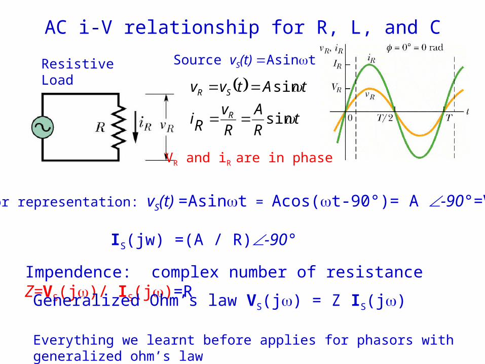
AC i-V relationship for R, L, and C
Resistive Load Source vS(t) Asint
tR
A
R
vRi
tAtvv
R
SR
sin
sin
VR and iR are in phase
Phasor representation: vS(t) =Asint = Acos(t-90°)= A -90°=VS(j)
IS(jw) =(A / R)-90°
Impendence: complex number of resistance Z=VS(j)/ IS(j)=R
Generalized Ohm’s law VS(j) = Z IS(j)
Everything we learnt before applies for phasors with generalized ohm’s law
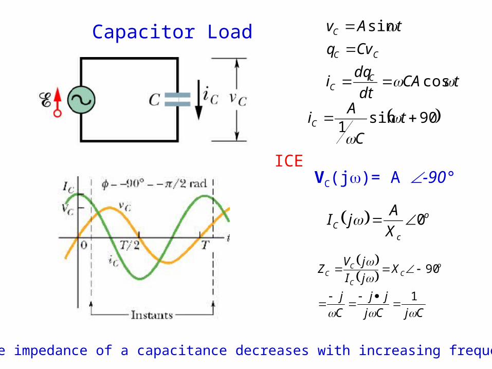
Capacitor Load
CjCj
jj
C
j
XjI
jVZ o
CC
CC
1
90
tCAdt
dqi
Cvq
tAv
CC
CC
C
cos
sin
90sin1
tC
AiC
ICE
VC(j)= A -90°
Notice the impedance of a capacitance decreases with increasing frequency
o
cC X
AjI 0
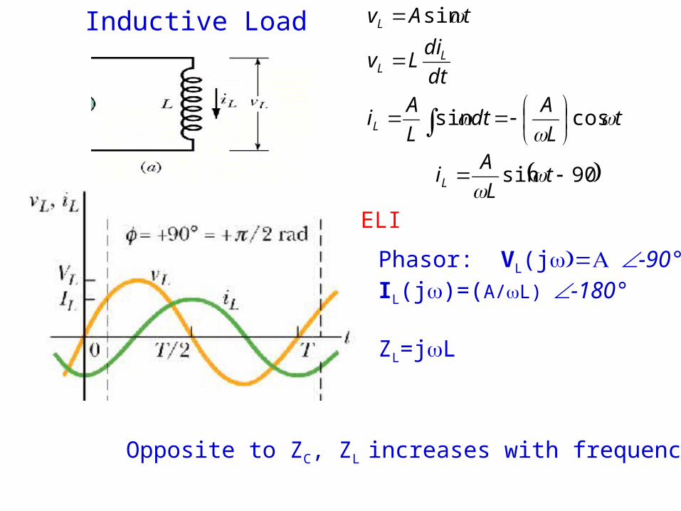
Inductive Load
tL
Adt
L
Ai
dt
diLv
tAv
L
LL
L
cossin
sin
90sin tL
AiL
Phasor: VL(j-90°IL(j)=(A/L) -180°
ZL=jL
ELI
Opposite to ZC, ZL increases with frequency
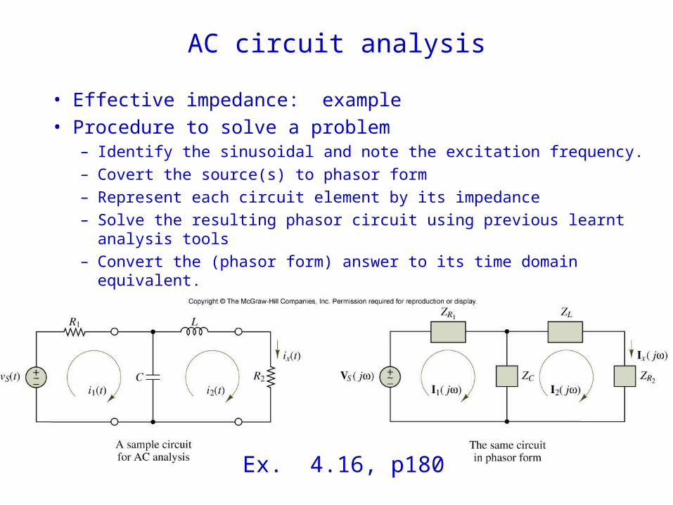
AC circuit analysis
• Effective impedance: example
• Procedure to solve a problem– Identify the sinusoidal and note the excitation frequency.
– Covert the source(s) to phasor form
– Represent each circuit element by its impedance
– Solve the resulting phasor circuit using previous learnt analysis tools
– Convert the (phasor form) answer to its time domain equivalent.
Ex. 4.16, p180
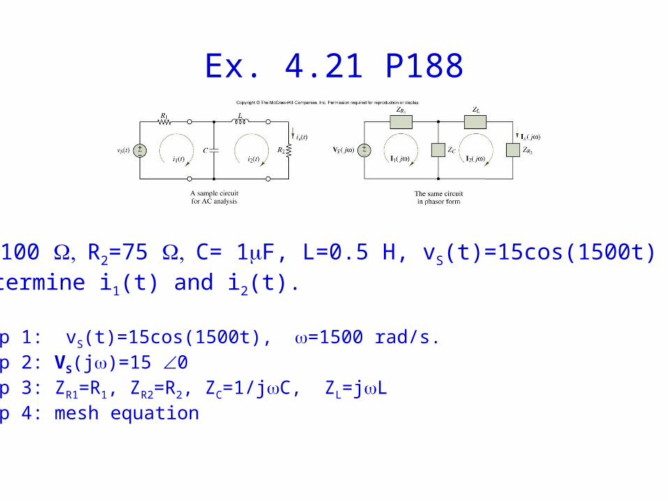
Ex. 4.21 P188
R1=100 R2=75 C= 1F, L=0.5 H, vS(t)=15cos(1500t) V.Determine i1(t) and i2(t).
Step 1: vS(t)=15cos(1500t), =1500 rad/s.Step 2: VS(j)=15 0Step 3: ZR1=R1, ZR2=R2, ZC=1/jC, ZL=jLStep 4: mesh equation