ac hotel atlanta international airport - winter companies€¦ · ac hotel atlanta international...
TRANSCRIPT

6160 Peachtree Dunwoody Rd. – Suite B200 – Atlanta, GA 30328 – P: 678-615-2901
www.ConsultDRB.com
Construction Advisors Serving Owners | Lenders | Developers
AC Hotel Atlanta International Airport College Park, Georgia
General Contractor Bidder
Request for Information & Responses May 3, 2017
1. Please provide specification or allowance for parking gate/parking control, or should
these be considered OFOI. Parking gate and controls will be by owner. Contractor to provide conduits, pull strings, and curbing as required.
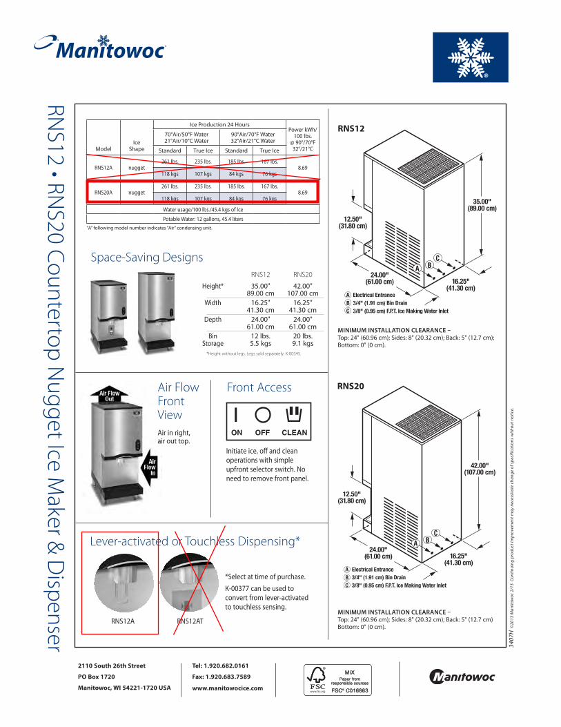
2. Please clarify if any equipment will be required at the hydro stations. Hydration stations are equipped with a Manitowoc RNS-20 Countertop Nugget Ice Maker & Dispenser. Cut sheet is included in this PDF file.
3. Please clarify if any warehousing of FF&E will be required. If required, please specify how many months for warehousing should be included with contract. Contractor to provide warehousing for all FF&E for a period of three months.
4. Drawings A4-11 and A4-12 (guest room detail) show connection for a lighted mirror in the bathrooms. Electrical drawing E4-03 does not indicate the lighted mirror connection. Please verify power outlet is required for the lighted mirror requirement. Please provide power outlet as indicated on architectural drawings. Electrical drawings will be updated.
5. In the Guest Room Bathrooms, should both power outlets be type EL-12 (GFI)? The detail indicates (1) EL-11 and (1) EL-12. This will work if the EL-12 is rated for feed through GFI protection. This is not indicated on the Legrand web site. All receptacles installed in the bathrooms shall be GFCI. This is noted on sheet E4-03. (DRP-C&O)
6. Panel E1LQA, Drawing E1-01, Room 110: This panel does not appear on the One Line Diagram (E0-02) or in the Panel Schedules (E7-01 through E7-05). Does this panel exist in this project? If so, please provide panel schedule and feeder info. Panel E1LQA is not required. (DRP-C&O)

7. Panel E1LQ, Drawing E0-02 and E7-01: This panel is indicated as a (2) section panel on the One Line Diagram (E0-02) and as a single section panel on Drawing E7-01. Which is correct? Panel E1LQ is a (2) Section Panel.
8. If plans and specs conflict with Marriott Mod 14 for fire alarm which should rule. Fire alarm system shall be provided in accordance with Mod 14 as a minimum for general requirements. All colors and finishes shall be provided per Mod 14 and Marriott standards. The Fire alarm system and components shall be provided to meet the Life Safety Systems – Lo Rise per specification section 28 31 00
9. Please verify if system smoke detectors in each unit are to receive low frequency sounder bases or individual low frequency horns. Provide with a sounder base capable of obtaining 75dBA “At the Pillow”
10. The drawings show (2) Electric Vehicle Charging Stations and associated circuits. The drawing notes call for (3) stations. Do we furnish (2) or (3) stations? There are no charging stations. Provide raceway only for future installation. See A0-02 for future locations.
11. Please clarify if water tap, vault, and meter are to be included under this cost or will it be performed and paid for by the local municipality. Per Prime Engineering: Water Tap, vault, and meter are to be included under this cost. Meter to be purchased from College park and installed by contractor.
12. Please clarify if sewer and water tap/impact fees will be included under this contract or paid for by the owner. Per Prime Engineering: Sewer and water tap/impact fees to be included under this contract.
13. Please clarify if builder’s risk is to be provided under this contract or paid for by the owner. Contractor to provide alternate for builder’s risk coverage for the project.
14. Please clarify if building permit costs are to be provided under this contract or paid for by the owner. Building permit costs are to be provided under this contract.
15. Please provide differentiation document indicating items to be OFOI, OFCI, and CFCI. See separate document included.

16. Please provide detail on how wood ceiling panels (type G) are attached to the structure. Are these to be wood panels per Room RCP details or laminate panels per finish spec OS-402. Panels are laminate per finish spec. OS-402. Center panel can be opened. Side of panel closest to closet to receive piano hinge. Opposite side to receive (2) quarter-turn latches.
17. Library Room 146: On the left side of the room in a recessed pocket, Drawing E8-01 calls for 4X Type LL4 and 4X Type LL4. Drawing LT-801 shows 1X Type LL1 and 4X Type LL4. Which drawing is correct? Drawing LT-801 is correct (1X Type LL1 and 4X Type LL4). See attached sheet DT-3.4 with mark-ups in red for clarification. Note: Per Marriott 90% Design Review and Owner direction, this piece of millwork will be deleted.
18. Light fixture Type “XL3” is not indicated on Drawings E8-01 or LT-801. Please clarify where this fixture is located. Type XL3 has been deleted.
19. Light Fixture Type “UL1” is not indicated on Drawings E8-01 or LT-801. Please clarify where this fixture is located. Type UL1 is not used.
20. Light Fixture Type “AL1” is not indicated on any lighting drawings. Please clarify where this fixture is located. Type AL1 is not used.
21. Riser Diagram General Notes and Riser Diagram Emergency and Life Safety Notes: Note 5, Emergency and Life Safety: The use of aluminum wire is not reference in the Specification section indicated. Please advise if aluminum cables can be used for the service entrance and panel feeders. Aluminum wire may be used for service feeders and panel feeders. The contractor is responsible for sizing the conduit and wire per code to meet the ampacity requirements noted in the contract documents. Conductors have been coordinated with the utility company utilizing copper. The contractor is required to coordinate all conductor sizes and material with the utility company and make sure proposed alternate wiring is compatible with utility company transformer, and proper connections are provided.

22. If aluminum wire is acceptable, please confirm that compression pin connectors are acceptable. Aluminum conductors may be used for the following if the same or larger capacity of those copper conductors shown or specified and conduit sizes are adjusted accordingly. Aluminum conductors shall be high compression type. All terminations shall utilize compression fittings. Conductors shall be torqued based on manufacturer's recommendation: service laterals, panel/switchboard distribution feeders 200 AMPS and larger terminating in switch gear, distribution panels, panelboards and transformers. All grounds shall be copper.
23. Please verify flooring material for kitchen. Altro USA, Inc., Altro Stronghold 30. Also, see Back-of-House Finish Legend on Sheet A9-01.
24. Please provide product or allowance for VCT in back of house areas. Armstrong, Excelon, 12 x 12 Also, see Back-of-House Finish Legend on Sheet A9-01.
25. Please provide product or material allowance for ceramic tile on exterior of building. Ceramic tile over 4" CMU has been replaced with 4" split-face block. Contractor to work with SRSS to find alternate products.
26. Note C7 on S0-01 notes to undercut building pad and replace with structural fill per the structural drawings. Foundation and SOG drawing S1-01 does not indicate how deep undercut should be. Please clarify depth of undercut required. See Paragraph 6.1 of Geotechnical Report in Volume 1 of Project Manual. Extent and depth of undercutting will be determined at the time of construction, after site has been stripped, cleared, and evaluated by the Geotechnical Engineer.
27. Please provide detail for operable partition support steel. See Detail 1/A11-01 and detail 8/S3-02.
28. Please clarify if the water feature requires any additional steel support? Water feature has been deleted.
29. Please clarify steel support required for public restroom vanities. See Detail 2/A11-01.

30. Please clarify steel support required for guestroom vanities. We understand the use of the A&M bracket has been approved by Marriott on other projects. SRSSA has no objection to their use on this project with the understanding that the General Contractor will provide sufficient metal stud support in the wall to accommodate loads from the bracket.
31. Please clarify if soap dish or foot rest will be required accessories for guestroom showers. Both soap dish and foot rest are required.
32. Detail 1/A4-12 shows fixture EL-06 over closet area. All other details show this light to be EL-01. Please confirm EL-01 is the correct fixture over the closet area. This fixture has been deleted. Drawings will be updated.
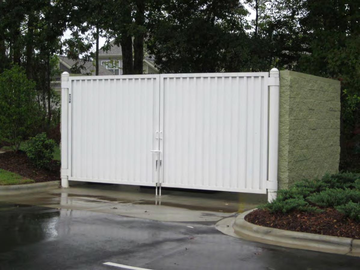
33. Reflected ceiling plan shows wood ceilings/soffits around porte cochere and over curtainwall along column line E. Detail 3/A3-11 indicates this to be metal panel. Please clarify. The soffits are prefinished aluminum panels. The RCP ceiling type designation should have been labeled "H".
34. Are “Reveal Light” in the Reception Desk, Detail 2 and 4, CFCI? If they are please provide fixture information, Cat. #/Manufacturer? The reveal light in the reception desk is CFCI. The fixture type is LL3. See Issue-for-Construction Project Manual, Volume IV, Page 29 of 49.
35. Please verify height of FRP panels on kitchen walls. 9'-0"
36. Please clarify if VWC or wall tile should be applied in guestroom bathrooms behind vanities. Walls behind vanities in guestroom bathrooms should receive VWC. See Project Manual Volume III, Interior Product and Finish Specifications, Item OS-322.
37. Specification 083800 provides a spec for rubber traffic doors. Interior drawing 1/EL-2.0 shows this door to be a wood door. Please clarify. Door 106 should be wood, Type B as shown on DT-3.13.
38. Please clarify if doors 119,120,139,142,143,144, and 145 are to be style and rail doors like detail 1 & 2 on DT-3.13 or flush wood doors. Doors are to be flush. See Door Schedule on Sheet A7-01.

39. What is the STC rating required for the entry and lounge area glazing systems? Required STC rating of lounge area glazing system is 52. No STC rating is required for glazing system at Entry Vestibule between column lines 7 and 8. Contractor to provide alternate price for replacing the triple-glazed, acoustic curtain wall at lounge with conventional, non-acoustic curtain wall.
40. What is the STC rating required for the guest room windows? Required STC rating of guest room windows is 54. See Project Manual Section 08 56 74 1.02 System Description Paragraph E.8
41. Please clarify product and finish of dumpster gates. Painted, welded steel tube frame with painted steel decking. See attached photo and drawings.
42. Please clarify product and finish of mechanical yard gates. Chain link gate. See Project Manual, Volume II, Section 32 31 13.
43. S2-02 shows a detail for tension piles, page S1-01 doesn’t show any tension piles. Please clarify All piles shown in details 8, 9, and 10 on S2-02 (caps under shear walls) should be considered tension piles.
44. Will irrigation be required for landscaping? Will an irrigation meter be required? Per Prime Engineering: Irrigation will be provided for small areas of the site where seasonal color to be provided.
45. Please clarify if any lockers will be required in the employee breakroom. Please provide specification and quantity. 24 lockers are required (12 in Men's Locker Room and 12 in Women's Locker Room) Basis-of-Design Manufacturer and Type: Republic Storage Systems Company "Standard Type", 12-inches wide x 18-inches deep x 36-inches high; double-tier, 72-inches total locker height. Other Acceptable Manufacturers: Lyon Workspace Products; Interior/Medart, Inc.; Penco Products, Inc.

47. Please confirm all signage to be OFOI. Site signage and building facade signage will be furnished and installed by the Owner. Contractor to install owner provided interior, non life-safety signage. Interior life-safety signage required for building CO to be provided and installed by Contractor. SRSS will provide Marriott Interior Signage Standards and design intent for egress signage.
48. Please verify if any wall protection will be required. If required provide specification and where it is to be located. Our understanding is that AC Marriott Design Standards do not require wall protection.
49. Please verify if any storage shelving will be required. Storage shelving is required in AC Market Storage 116, Janitor 122, Luggage 130, and Storage 140.
50. Please clarify if any residential appliances are to be included under the contractor’s scope of work, or if they are all OFOI. Residential appliances will be furnished by the Owner and installed by Contractor.
51. Please clarify if floor mats are to be included under the contractor’s scope of work, or if they are all OFOI. Walk-off mats are part of the Contractor's scope. The mats (Item C-4) are specified in the Project Manual, Volume V, Issue for Construction, Page 28 of 224. The mats would be installed in Vestibule 101 and Vestibule 124.
52. Drawing P4-04 indicates the 4” grey water shall enter the building below grade at the SW corner of the Pump Room with a note to see Civil plans for continuation and a Key Note to refer to the Civil plans for the exact location of the grey water pump, filtration system and vault. The Civil plans, C-205 & C-206, indicate the vault to be approximately where the storm line exits the building, however there is no routing of the storm connection or the grey water piping indicated. Grey water pump, filtration system and vault have been eliminated for the initial construction. Care should be taken to facilitate adding this system at a later date.
52. Please provide routing for grey water piping re-entering the building. Grey water pump, filtration system and vault have been eliminated.
53. Please provide locations for the grey water pump and filtration system. Grey water pump, filtration system and vault have been eliminated.

54. In reading the specification on DV0-00 we noticed a discrepancy in the manufacturers that they are requesting. At the bottom of the structured cabling system components specification list, it requests that we quote Superior Cable with Leviton jacks. Leviton is no longer the warranty partner with Superior. Ortronics is. Leviton is now partnered with Berk-Tek. Will a Leviton/Berk-Tek solution be an acceptable alternate? Alternate is acceptable as proposed.
55. Drawing A1-01 notes eyewash in engineering room 131 next to office wall. Plumbing show this eyewash station next to floor drain on storage room wall, please confirm plumbing drawing location is correct. Plumbing drawing is correct. Eyewash station should be near floor drain. Architectural drawing will be revised.
56. Please confirm spray-on insulation thickness required as shown on A-311 and A-312. Spray-on insulation should be applied in thickness to achieve R-12. (3 to 4 inches. Confirm with manufacturer.) Spec. section for spray-on insulation is attached.
57. Detail 2/A3-12 shows what appears to be a 4” curb inside the guestroom on the exterior wall. Blown up detail 7/A6-11 this curb does not appear. Please confirm that this curb does not existing per detail 7/A6-11. There is no curb. Detail 7/A6-11 is correct. Detail 2/A3-12 has been revised.
58. Please confirm note 14 on guestroom drawings for mold and mildew texture finish is required. Confirmed. Note 14 on guestroom drawings will be deleted.
59. Please confirm note 12 on guestroom drawings should be deleted. All guestroom bathrooms to included OFCI VWC item 322 on walls and wall tile is not required. Confirmed. Note 12 on guestroom drawings will be deleted.
60. Please confirm note 22 on guestroom drawings should be deleted. All bathroom vanities will be secured to the wall per A & M brackets. We understand use of this bracket has been approved by Marriott on other projects. SRSSA has no objection to their use on this project with the understanding that the General Contractor will provide sufficient metal stud support in the wall to accommodate loads from the brackets.

61. Per the equipment schedule on sheet K100, item #30 is shown to label (1) floor trough. However, per kitchen equipment floor plan 1/K100, there are (4) item #30s, with only (1) item 30 showing a floor trough. The other (3) item #30s do not appear to label anything. Please clarify what the other (3) item #30s represent. The other (3) item #30's should be deleted.
62. Detail 3 & 4 /A6-11 show a 6” wide x by 4” high? concrete curb at roof edge on level 2. This curb is not shown on the structural drawing S1-02. Please clarify reinforcement requirements. See Detail 8/S2-01 for typical concrete curb reinforcement details.
63. Drawing AR+E-1.3 shows a floor drain behind bar. Plumbing drawing P4-03 does not show this drain. Please clarify if it is required. \ Floor drain is required. Plumbing/Food Service drawings will be revised.
64. Please verify upholstery on banquette sitting UP-2 is OFOI. Confirmed.
65. Drawing A-401B notes partitions between restroom stalls to be type XA2X, to the underside of the structure. Drawing EL 2.1 shows these walls to be wall hung partitions wrapped with VWC about 8’ high and 9” off of the floor. Please clarify correct partition type. Partition construction is type XA2X (2 1/2" metal stud with 5/8" GWB each side). Partition containing door to stall is full height and extends from floor to 6" above ceiling. Partitions between stalls start 9" above floor and terminate 12" below ceiling as shown on HBA detail 10/DT-3.13.
66. Please clarify what signage shown in the volume 3 specifications should be included in the bid. Please refer to item # 47 above.
67. Please clarify location of steel hand rails and stairs noted on detail 1/C-404. Site drawing C-204 does not identify any site stairs. No stairs are required. Steel handrail is for ramp. See Note No. 1, Detail 8/C4-04.
68. Please provide detail 5/C-404 for chain link fence per C-204. Verify height of all chain link fencing to be 4’. Detail will be provided by Civil Engineer.

69. Please provide detail or specification for dumpster gates. See attached drawing and photograph.
70. Please verify grease trap size. Grease trap size will be provided by Civil Engineer. SRSS suggests including cost for (2) 1515-gallon tanks until requirements are confirmed by City of College Park.
71. Please verify hydro stations on floors 3, 5, & 7 have been deleted. Plumbing drawings do not show a floor drain or running to this location on those floors, but backgrounds of cabinetry still show up on those floors. Confirmed. Hydro stations on Floors 3, 5 & 7 have been deleted. Millwork appearing on plumbing drawings will be deleted. See Architectural details 1, 2, 10, 11 & 12 on A4-02 for core layouts and locations of hydration stations. Note: Per Marriott 90% Review and Owner direction, all floors will have a hydration station consisting of a 2'-9" wide by 8'-0" tall piece of millwork equipped with a Manitowoc RNS-20 Countertop Nugget Ice Maker & Dispenser. Countertops have been deleted.
72. Please confirm roofing membrane to be TPO,specification 075324 provided is for a PVC roofing membrane. Confirmed. Roof membrane will be TPO. Please see attached spec. section.
73. Please confirm standard color shop fabricated coping is acceptable. Confirmed. Standard color shop fabricated copings are acceptable.
74. Please confirm ceilings not label on RCP drawingA8-01 are to be type ‘F’ open to structure; Specifically, rooms 119, 120A, 126, and 128. Confirmed. Rooms noted are open to structure.
75. Please confirm 1 flagpole per A0-02 is correct in lieu of the 3 shown on C-204. Confirmed. Sheet A0-02 with 1 flagpole is correct.
76. Please confirm insulation on cold water piping is to be excluded, specification 220700 notes to provide insulation for cold water piping. Confirmed. Insulation on cold water piping is to be excluded.
77. Please confirm alternate manufacturers are acceptable for AV speakers. Drawing AV0-01 only lists 1 manufacturer for speakers and equipment. Atlas speakers shown on VE Log are acceptable.

78. S1-01 shows ¾” depression for lobby areas. With 24” x 24” and 24” x 12” tile it is our understanding the depressed slab is not required. Please clarify depressed slab as shown on S1-01 is not required. SRSS recommends maintaining the 3/4" depression for 24" X 24" and 24" X 12" tile.
79. Drawing A6-12 shows a fully tapered insulation on roof. Please clarify roof structure will be sloped to drains to avoid a fully tapered roof system. Roof structure is sloped from sides toward the centerline of the building. Intermediate slopes between roof drains can be achieved with either a concrete topping slab or tapered insulation. A "fully" tapered insulation roof system was not intended.
80. Please confirm solar panels will not be included in this scope of work. Confirmed. Solar panels are not included in this scope of work.
81. A5-01, please verify if rail is required on 1st floor fire stairs to restrict access underneath stairs. Yes, per ADA, a 27-inch high rail is required where vertical clearance is less than 80 inches. Note: Per Marriott 90% Review and Owner direction, provide a one-sided drywall partition (Type XF3X) to underside of stair stringer and landing.
82. Please verify floor finish required in ADA guestrooms with roll in shower that will allow slope to drain. Please clarify if a drain outside the shower will be required. The concrete slab at ADA shower pan locations is depressed 1-inch. Vinyl flooring in baths is to be installed per manufacturer's recommendations for wet locations. SRSS will work with Contractor and the manufacturer to confirm transition details. Note that roll-in showers are required at Rooms 222, 240, and 322 only. Drains outside the roll-in showers are required.
83. Please clarify where criteria note 23 on A4-03 applies. It does not show up on guestroom plans. Note 23 pertains to accessible guestrooms and appears on details H/A4-05 and H/A4-10. Per ADA Guidelines, water supply and drain pipes under lavatories must be insulated to protect against contact.
84. Please clarify if corner guards will be required in guestrooms. Unless required by Marriott on other projects, we see no requirement for corner guards in guestrooms.

85. Please clarify if any light fixtures or AV equipment will require structural support and provide detail. No AV equipment requires structural support. Pendant light fixtures at AC Breakfast will require support.
86. Drawing 4-11 does not show a pre wired head board. Please verify headboards will be pre wired and outlets provided by the owner. Adorn headboards will be pre-wired and provided by the owner for contractor installation.
87. Please verify porte cochere requires a dry pipe sprinkler system. Yes this will require a dry pipe sprinkler system
88. Please verify CPVC piping is acceptable for fire sprinkler systems as allowed per code. Yes this is an acceptable alternative if approved by the owner.
89. The RFP states that there is a goal for WMBE participation. Please identify that goal percentage. The goal is 35%
90. We are assuming all permit fees are being carried by the Owner. Please confirm. Building permit costs are to be provided under this contract.
91. Please clarify the scope of work to be included with the FF&E installation line item. ALL FF&E to be installed by GC. Please see responsibility matrix attached.
92. In the ID Specification Manual, it mentions an Appendix III which is to have a list of
FF&E vendors by area. We could not locate that Appendix. Please provide. We assume you are referring to the appendices mentioned on page 471 of 767 in Volume III of the Project Manual. The content of Volume III was provided by Marriott and did not include a list of FF&E vendors by area.
93. Please confirm all laundry and kitchen equipment (furnish and install) is to be included in our total cost.
Provide pricing for F&I as an alternate.
94. Please confirm all fitness equipment (furnish and install) is to be included in our total cost. Provide pricing for F&I as an alternate.

95. Please provide a specification for the employee lockers. 24 lockers are required (12 in Men's Locker Room and 12 in Women's Locker Room) Basis-of-Design Manufacturer and Type: Republic Storage Systems Company "Standard Type", 12-inches wide x 18-inches deep x 36-inches high; double-tier, 72-inches total locker height. Other Acceptable Manufacturers: Lyon Workspace Products; Interior/Medart, Inc.; Penco Products, Inc.
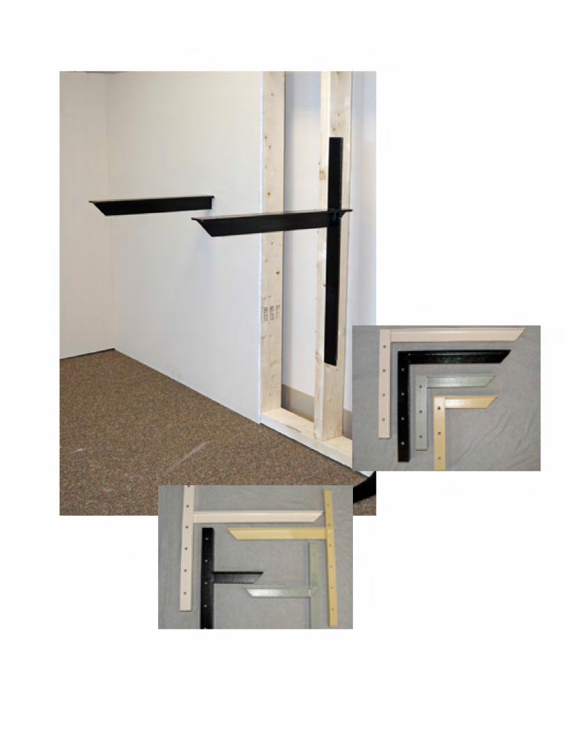
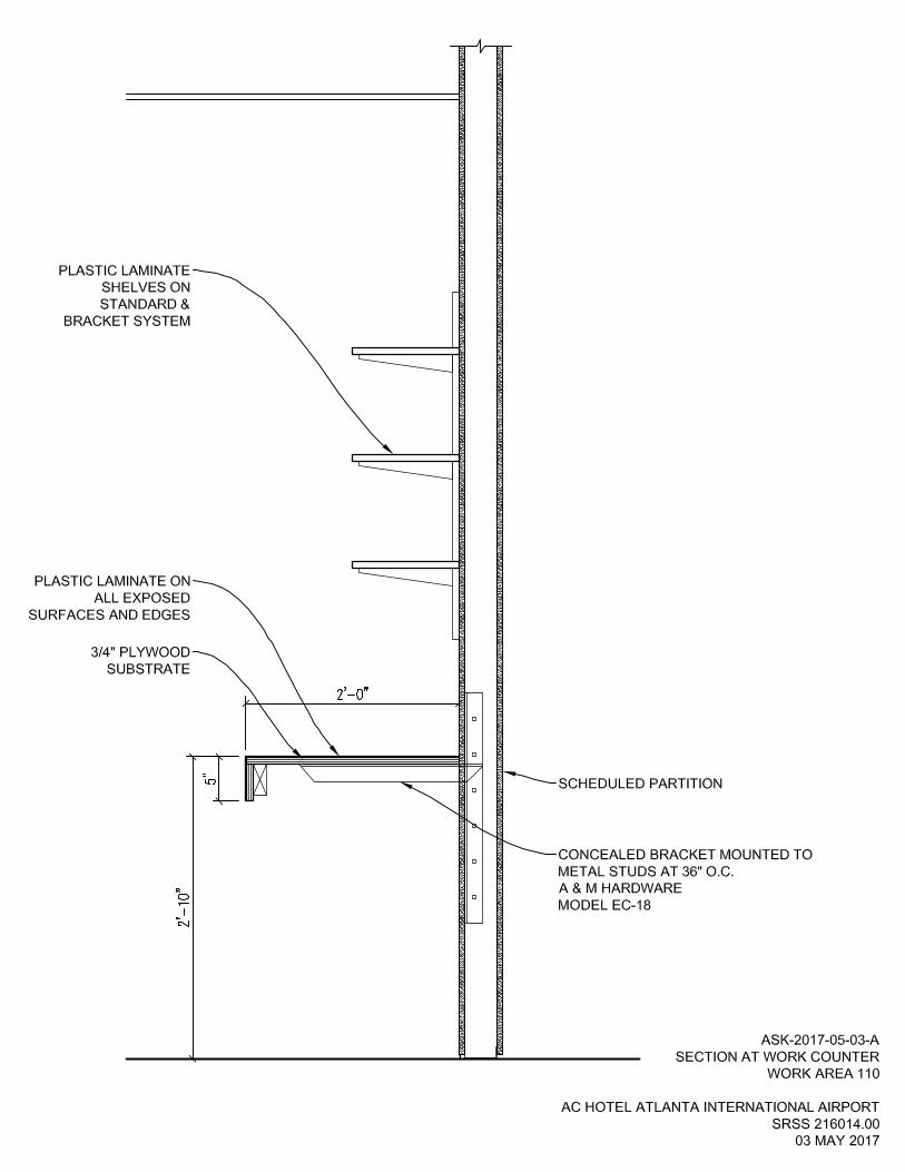
96. Please provide a section/detail for millwork/shelving items in Luggage 130, Work Area 110 and Employee Breakroom 125. For Work Area 110, provide 11 linear feet of plastic laminate base cabinets and countertop. Provide 12 linear feet of work counter. Provide adjustable shelving on standard and bracket system above base cabinets and work counter. For work counter, see attached sketch ASK-2017-05-03-A and cut sheet from A & M Hardware. For Employee Breakroom 125, provide 5 linear feet of plastic laminate base cabinets, countertops and wall cabinets. For Luggage 130, provide (3) 4-tier metal shelving units. Uline Model No. H-2945-54 or similar. Also include (3) 1-inch, one-hole straps secured to blocking in the wall at each post located along a wall.
97. Please designate where the walk in cooler and freezer condensing units are to be located.
Condensing Units are to be located on a concrete pad on grade, near the door to the kitchen. Plan will be updated to show location.
98. Please confirm that LEED gold is the desired LEED accreditation and if not, which level is to be achieved.
LEED is desired but no specific level is set due to a cost savings effort for the project. For purposes of the pricing provide an alternate for performing LEED activities with a target of LEED certified or LEED silver.
99. If a LEED Silver or Certified is the desired level, please provide a revised point plan designating the changes in points.
Updated point plan will be available after bid date but prior to final contract.
100. Enhanced Commissioning is listed as required on the LEED checklist. Please confirm that the Owner will carry that cost.
The owner will carry that cost.
101. Please provide the name of the Firm that will be providing LEED consultation and administration on the project.
Epsten Group, Alicia Case.

102. The bid form lists landscaping and irrigation, however, there is no specification for the irrigation system. Please provide specification or allowance.

115/60/1. (230/50/1 also available.) 115/60/1 ice machines are factory pre-wired with a 6' (180 cm) power cord and NEMA 5-15P-plug configuration. 230/50/1 ice machines are factory pre-wired with a 6' (180 cm) power cord only, no plug is supplied.
Total ampacity: Air-cooled: 10.3 amps.
Maximum fuse size: Air-cooled: 15 amps.
HACR-type circuit breakers can be used in place of fuses.
Models
Operating Limits: • Ambient Temperature Range:
45˚-110˚F (7.2˚-43.3˚C)
• Water Temperature Range: 45˚-90˚F (7.2˚-32˚C)
• Water Pressure Ice Maker Water In: Min. 20 psi (137.9 kPA) Max. 80 psi (551.1 kPA)
Specifications
• New bite-sized nugget boasts 90% ice content* with only 10% water offering one of the best nugget ratios for maximum cooling and minimal drink dilution.
• Up to 261 lbs. (118 kgs) standard daily ice production including ice and water content. True Ice production calculates just the ice produced helping end users size their machine and plan for their needs. Up to 235 lbs. (107 kgs) of True Ice daily production.
• New DuraTech™ front panel for easy cleaning and reduced hardwater staining in the dispense area.
• Only 16.25" (41.28 cm) wide by 24.00" (61.00 cm) deep by 35.00" (89.00 cm) tall on the RNS12 and 42.00" (107.00 cm) tall without legs; legs sold separately.
• Trouble-free ice dispensing. Simply place cup under chute and activate.
• Two ice activation options: activation arm or touchless.
• Dispense opening (10.50"/ 26.67 cm) from grate to chute maximizes clearance for tall containers.
• Larger drain pan minimizes ice spillage.
• Blue LED light provides dispense visibility for rooms with limited ambient light.
• Water and drain connections in back or bottom of unit for flush mounting.
• Manitowoc’s patented cleaning technology manages the cleaning process from start to finish.
*70/50˚ F
RNS12 • RNS20Countertop Nugget Ice Maker & Dispenser
RNS12 • RN
S20 Countertop N
ugget Ice Maker & D
ispenser
2110 South 26th Street
PO Box 1720
Manitowoc, WI 54221-1720 USA
Tel: 1.920.682.0161
Fax: 1.920.683.7589
www.manitowocice.com
RNS20
Ice Machine Electric
RNS-12A RNS-12AT RNS-20A RNS-20AT
RNS12
Nugget ice consists of small pieces ranging from 3/8" to 1/2" in width and length on average. Offers a 90% ice to water ratio with a softer, chewable texture while still providing maximum cooling effect and great dispensibilty.
Ice Shape
Three dispense settings are standard: ice only, water only, or ice and water.
BTU Per Hour: 2,300 (average)
Compressor: Nominal rating: 1/3 HP
Refrigerant: R404A
YEAR PARTS2 YEAR LABOR
COMPRESSORICE MAKER
YEAR PARTS2 YEAR LABOR
ModelIce
Shape
Ice Production 24 HoursPower kWh/
100 lbs.@ 90°/70°F
32°/21°C
70°Air/50°F Water 21°Air/10°C Water
90°Air/70°F Water32°Air/21°C Water
Standard True Ice Standard True Ice
RNS12A nugget261 lbs. 235 lbs. 185 lbs. 167 lbs.
8.69118 kgs 107 kgs 84 kgs 76 kgs
RNS20A nugget261 lbs. 235 lbs. 185 lbs. 167 lbs.
8.69118 kgs 107 kgs 84 kgs 76 kgs
Water usage/100 lbs./45.4 kgs of Ice
Potable Water: 12 gallons, 45.4 liters
RNS12 • RN
S20 Countertop N
ugget Ice Maker & D
ispenser
2110 South 26th Street
PO Box 1720
Manitowoc, WI 54221-1720 USA
Tel: 1.920.682.0161
Fax: 1.920.683.7589
www.manitowocice.com
3407
H ©
2013
Man
itow
oc 2
/13
Con
tinui
ng p
rodu
ct im
prov
emen
t may
nec
essi
tate
cha
nge
of s
peci
ficat
ions
with
out n
otic
e.
16.25"(41.30 cm)
A BC
35.00"(89.00 cm)
24.00"(61.00 cm)
12.50"(31.80 cm)
Electrical Entrance3/4" (1.91 cm) Bin Drain3/8" (0.95 cm) F.P.T. Ice Making Water Inlet
ABC
Initiate ice, off and clean operations with simple upfront selector switch. No need to remove front panel.
Front Access
16.25" (41.30 cm)
A BC
42.00" (107.00 cm)
24.00" (61.00 cm)
12.50" (31.80 cm)
Electrical Entrance 3/4" (1.91 cm) Bin Drain 3/8" (0.95 cm) F.P.T. Ice Making Water Inlet
A B C
“A” following model number indicates “Air” condensing unit.
MINIMUM INSTALLATION CLEARANCE – Top: 24" (60.96 cm); Sides: 8" (20.32 cm); Back: 5" (12.7 cm) Bottom: 0" (0 cm).
Space-Saving Designs
RNS12 RNS20
Height* 35.00" 42.00" 89.00 cm 107.00 cm Width 16.25" 16.25" 41.30 cm 41.30 cm Depth 24.00" 24.00" 61.00 cm 61.00 cm Bin 12 lbs. 20 lbs. Storage 5.5 kgs 9.1 kgs
*Height without legs. Legs sold separately: K-00345.
RNS12
RNS20
Lever-activated or Touchless Dispensing*
*Select at time of purchase.
K-00377 can be used to convert from lever-activated to touchless sensing.
RNS12ATRNS12A
MINIMUM INSTALLATION CLEARANCE – Top: 24" (60.96 cm); Sides: 8" (20.32 cm); Back: 5" (12.7 cm); Bottom: 0" (0 cm).
Air Flow Front View Air in right, air out top.

Call To Order (888) 647-02002705 Mount Joy Road, Manheim, PA 17545 | Fax: (717) 653-5874
www.AandMhardware.com
Black 909-58
White 933-58
Gray 961-58
Almond 920-58
Formica color matches:
CONCEALED BRACKETS
Concealed Brackets with 9” to 30” Support ArmMounting Hardware Included - ( 3/8” - 16 x 3” carriage bolt assemblies )
2 - 58/ea 60+/ea
Bracket Size USA Import USA Import Pcs/Wgt/Box*
C - 9” $27.85 $21.85 $26.45 $20.35 2 pcs/11 lbs
C - 12” $29.85 $23.45 $28.35 $21.95 2 pcs/12 lbs
C - 18” $35.05 $29.05 $33.30 $27.55 2 pcs/18 lbs
C - 24” $39.95 $31.85 $37.95 $30.35 2 pcs/22 lbs
C - 30” n/a $33.35 n/a $31.70 2 pcs/27 lbs
Extended Concealed Brackets with 9” to 30” Support ArmMounting Hardware Included - ( 3/8” - 16 x 3” carriage bolt assemblies )
Bracket Size 2 - 58/ea 60+/ea Pcs/Wgt/Box*
EC - 9” $24.10 $22.60 2 pcs/14 lbs
EC - 12” $25.80 $24.30 2 pcs/16 lbs
EC - 18” $31.50 $30.00 2 pcs/22 lbs
EC - 24” $35.20 $33.70 2 pcs/24 lbs
EC - 30” $47.05 $44.70 2 pcs/31 lbs


FOR INFORMATION ONLY
SECTION 07 21 29
SPRAYED-ON INSULATION
PART 1 - GENERAL
1.01 REFERENCE STANDARDS
A. American Society for Testing and Materials (ASTM):1. C1149 Self-Supported Spray-Applied Cellulosic Thermal Insulation
1.02 SUBMITTALS
A. General: In compliance with Section 01 33 00 and as specified herein.
B. Product Data: ManufacturerUs specifications and product data on materials and installation instructions.1. Edit data to delete nonapplicable information.2. Include thickness, density, k-factor, U-value and C-value for given thicknesses and formula used
to obtain values of sprayed-on insulation.
C. Samples: Full line of colors and textures for sprayed-on insulation for Architect’s selection.
D. Letter of Conformance; (FIO): In compliance with requirements of, and in format included in, Section01 33 00.
PART 2 - PRODUCTS
2.01 ACCEPTABLE MANUFACTURERS
A. Basis-of-Design Manufacturer and Type: International Cellulose Corporation, "K-13 Type", Class 1,Class A flame spread rating, natural cellulose material chemically treated to resist fire, mold and mildewblended with adhesive binder. Color to be selected by Architect from manufacturer’s standard colors.1. Thermal Performance as on Drawings.2. Sprayed-on Insulation Characteristics:
a. Fire Hazard Classification:1) Flame Spread: 5.2) Smoke Developed: 5.
b. Bond strength shall be greater than 100 psf in compliance with ASTM E 736.c. In compliance with ASTM E 84/ UL 723.d. Non-corrosive per ASTM C 739.e. Bond Deflection per ASTM E 759: 6" Deflection in 10' Span - No Spalling or Delamination.f. R-Value to be 3.75 per inch per ASTM C518.g. Comply with IBC 803.3/2009 IBC 803.10 stability requirements for interior finishes.h. Meet ASTM C 1149.
B. Protective Coating: International Cellulose Corporation. “ProTek-13®" protective coating with flamespread not to exceed 5, Class A, and tested in compliance with ASTM E84.
C. Other Acceptable Products: Subject to compliance with all requirements of this specification, providenamed products and systems, or comparable products and systems, by one of the followingmanufacturers:1. Thermocon International "ThermoCon".
Atlanta Airport AC Hotel Sprayed-On Insulation216014.00 - © Copyright 2016 Smallwood, Reynolds, Stewart, Stewart & Associates, Inc. Atlanta, Georgia 07 21 29.1

FOR INFORMATION ONLY
PART 3 - EXECUTION
3.01 INSTALLATION
A. Inspect surfaces to which material is to be applied. Do not begin application until surface is acceptable.
B. Apply in thickness to underside of concrete slab where indicated to obtain R-value as indicated onDrawings. Use primer or adhesive recommended by manufacturer.
C. Apply only by factory trained applicators. Treat insulation in plenums with protective coating to preventdusting or particles entering air system.
3.02 PROTECTIVE COATING INSTALLATION
A. Provide masking, drop cloths or other satisfactory coverings for all materials/surfaces which are not toreceive protective coating so as to prevent damage from overspray.
B. Installation of Protective Coating:1. Surface to receive protective coating shall be firmly adhered to substrate and free of loose material,
oil, scale or other such material that would impair bonding of protective coating. When applyingprotective coating to sprayed insulation materials, these products must be properly installed andfully cured prior to installing protective coating.
2. Install coating per manufacturer’s instructions using approved application equipment.3. Apply at rate sufficient to obtain uniform coverage of substrate. Multiple opposing passes may be
required depending on surface texture.4. Provide natural or mechanical ventilation to properly dry coating.
C. Coordinate Work with other trades whose work may be affected or have an effect on installation ofsprayed protective coating.
D. Installation, clean-up and curing shall be accomplished according to manufacturer’s recommendationsand common construction standards.
END OF SECTION
Atlanta Airport AC Hotel Sprayed-On Insulation216014.00 - © Copyright 2016 Smallwood, Reynolds, Stewart, Stewart & Associates, Inc. Atlanta, Georgia 07 21 29.2

Issued For ConstructionFOR INFORMATION ONLY
SECTION 07 53 24
FULLY ADHERED SINGLE PLY ROOF MEMBRANE SYSTEM
PART 1 - GENERAL
1.01 SUBMITTALS
A. General: In compliance with Section 01 33 00 and as specified herein.1. Make all submittals prior to preroofing conference.
B. LEED Submittal:1. Product Test Reports for Credit SS 7.2: For roof materials, indicating that roof materials comply
with Solar Reflectance Index (SRI) requirement of 78.2. Product Data for Credit MR 4.3 and Credit MR 4.4: For products having recycled content,
documentation indicating percentages by weight of postcconsumer and preconsumer recycledcontent.a. Include statement indicating costs for each product having recycled content.
3. Product Data for Credit MR 5.1 and Credit MR 5.2: Provide product certificates for products andmaterials required to comply with requirements for regional materials indicating location anddistance from Project of material manufacturer and point of extraction, harvest, or recovery for eachraw material. a. Include statement indicating cost for each regional material and the fraction by weight that is
considered regional.
C. Product Data: Submit manufacturerUs product data, clearly marked to indicate materials and conditionsapplying to roof membrane system installation. Indicate fastener location and spacing.
D. Shop Drawings: One reproducible original and one blue or black line print showing:1. Roof plan indicating locations of factory and field made seams, splices, drains, penetrations and
equipment. Minimum scale 1/16" = 1U-0".2. Design details showing expansion joints, penetrations, drains, perimeter and wall flashings.
Minimum scale 3" = 1U-0".3. Roofing manufacturerUs prior approval and number assignment.
E. Certification: Submit for ArchitectUs information only.1. Submit certification that proposed applicator is approved for warranted Work by membrane
manufacturer.2. Submit certification from authorized representative of roof membrane system manufacturer stating
that surfaces and conditions are acceptable for purpose of providing specified warranty.3. Submit roofing manufacturerUs written approval of all roofing materials to be used not supplied by
roofing manufacturer.4. Roof membrane manufacturerUs certification that roof membrane system provided for roofing Work
for this Project is approved for use with UL tested fire-rated assemblies indicated.
F. Maintenance Data: Submit in compliance with Section 01 77 00, complete set of maintenance data andinstructions detailing preventative maintenance and noting list of harmful substances which maydamage roofing membrane.
G. Intent to Warrant: Submit an intent to warrant, executed by authorized representative of roof membranesystem manufacturer, indicating manufacturer has reviewed Construction Documents, conditionsaffecting Work and relationship of roof membrane and insulation and proposes to provide warrantiesas referenced herein without further stipulation.
Atlanta Airport AC Hotel Fully Adhered Single Ply Roof Membrane System216014.00 - © Copyright 2016 Smallwood, Reynolds, Stewart, Stewart & Associates, Inc. Atlanta, Georgia 07 53 24.1

Issued For ConstructionFOR INFORMATION ONLY
1.02 QUALITY ASSURANCE
A. Assume full responsibility for complete, successful installation in compliance with roofing manufacturerUsspecifications and performance requirements specified herein.1. If any specified requirements are such that impair life, serviceability or intended function of
insulation, roofing and flashing, notify Architect of such and do not proceed with Work untilconditions are resolved.
B. Roofing applicator to be approved in writing by roofing manufacturer.
C. Upon completion of installation, and during installation if requested by Owner, roofing manufacturerUsauthorized representative shall inspect application for assurance of manufacturerUs warranty.
D. Testing Laboratory Services:1. If required by Owner, independent testing laboratory will perform on-site quality control observations
and perform laboratory analysis of new roofing and insulation at OwnerUs cost.2. Owner may employ the services of an independent consultant to act as his representative.
E. Regulatory Requirements: UL Class A Fire Hazard Classification.
1.03 PREROOFING CONFERENCE
A. Prior to beginning roofing Work, preroofing conference will be held to review Work to be accomplished.1. Contractor, Architect, roofing subcontractor, roof membrane system manufacturerUs representative
and all subcontractors who have equipment penetrating roo f or whose work involves access toroof shall be present.
2. Contractor shall notify Architect minimum seven days prior to time for conference.3. Contractor shall record minutes of meeting and distribute to attending parties.
B. Immediately prior to application of roof membrane system, sweep roof deck, removing debris andforeign material. Verify that installed insulation is suitable for roofing application.
1.04 DELIVERY, STORAGE AND HANDLING
A. Store materials in dry, covered storage, off ground. Handle roll goods to prevent damage to edges. Deliver all materials and packages in manufacturer's original unopened containers, with legible labelsintact.
B. Store solvent bearing materials in dry, cool storage and keep lids tight on opened containers to preventsolvent escape.
1.05 JOB CONDITIONS
A. Apply roof membrane system in dry weather in compliance with manufacturer's instructions. Undertakeapplication only when forecasted weather conditions predict suitable installation conditions.
B. Protection:1. Protect building from damage and defacing by roofing operations.2. Restore or replace adjacent work or materials damaged during handling of roofing materials.3. Provide protection or avoid traffic on newly completed roof surfaces.
C. Surfaces to receive roof membrane system shall be cleaned, smooth, free of projections, grease, oiland foreign material. Commence application only after surfaces are in proper condition to receive roofmembrane system.
Atlanta Airport AC Hotel Fully Adhered Single Ply Roof Membrane System216014.00 - © Copyright 2016 Smallwood, Reynolds, Stewart, Stewart & Associates, Inc. Atlanta, Georgia 07 53 24.2

Issued For ConstructionFOR INFORMATION ONLY
D. Ascertain work of other trades penetrating roof membrane system or intended to be made watertightby membrane application is in place and accepted prior to installation of roof system. Schedule roofingapplication to minimize traffic on membrane.
E. Cements and bonding adhesives contain petroleum distillates and are extremely flammable. Do notbreathe fumes or use near open flame or sparks.
F. Maintain roof surface free of ponded water, ice or snow to eliminate future condensation problems.
1.06 WARRANTY
A. Contractor: Provide Owner written warranty that insulation, roofing, and flashing systems are free fromdefects in materials and workmanship and will not leak for period of two years from date of SubstantialCompletion and that defects occurring during said period shall be promptly corrected at no additionalcost to Owner.
B. Manufacturer: Provide Owner with written warranty that roofing and flashing shall remain watertight andshall not leak for period of twenty years from Date of Substantial Completion. Warranty shall cover alllabor and material required to maintain these conditions at no additional cost to Owner. Include costof warranty in Contract Sum.
C. Contractor to confirm warranty is applicable if solar panels are installed after roofing system is installed. Provide manufacturer information recommended provisions to allow for solar panel construction at laterdate.
PART 2 - PRODUCTS
2.01 ROOF MEMBRANE SYSTEM
A. Manufacturer and Type: Firestone Building Products Company “UltraPly TPO” 60 mil thick ScrimReinforced Thermoplastic Roofing System with following characteristics:1. Thickness: 60 mils nominal.2. Exposed Face Color: White.3. Physical Properties:
a. Breaking Strength: 225 lbf; ASTM D751, grab method.b. Elongation at Break: 15 percent; ASTM D751.c. Tearing Strength: 55 lbf minimum; ASTM D 751, Procedure B.d. Brittleness Point: Minus 22 deg F.e. Ozone Resistance: No cracks after sample, wrapped around a 3-inch diameter mandrel, is
exposed for 166 hours to a temperature of 104 deg F and an ozone level of 100 pphm; ASTMD1149.
f. Resistance to Heat Aging: 90 percent minimum retention of breaking strength, elongation atbreak, and tearing strength after 166 hours at 240 deg F; ASTM D573.
g. Water Absorption: Less than 4 percent mass change after 166 hours’ immersion at 158 degF; ASTM D471.
h. Linear Dimension Change: Plus or minus 2 percent; ASTM D1204.
B. Other Acceptable Manufacturers:1. Carlisle SynTec Systems.2. Johns Manville.
Atlanta Airport AC Hotel Fully Adhered Single Ply Roof Membrane System216014.00 - © Copyright 2016 Smallwood, Reynolds, Stewart, Stewart & Associates, Inc. Atlanta, Georgia 07 53 24.3
Issued For ConstructionFOR INFORMATION ONLY
C. Component Materials: As manufactured by or as certified by membrane manufacturer as tocompatibility; including:1. Laminated Metal Flashings.2. Bonding adhesive.3. Mastic.4. All purpose sealant.5. Prime and solvent.6. Seam sealant.7. Overnight seal.8. Sealant.9. Mechanical fasteners.10. Perimeter half sheets.
2.02 RELATED MATERIALS AND ACCESSORIES
A. Insulation: Polyisocyanurate foam core, thickness to achieve a continuous Long-term ThermalResistance (LTTR) Value of 23.6; regular and tapered. Rigid, cellular polyisocyanurate thermalinsulation with core formed by using HCFCs as blowing agents to comply with ASTM C1289, Type II,with felt or glass-fiber mat on both major surfaces. Following are approved insulations:1. Atlas Energy Products "AC Foam-II" with glass fiber reinforced facers.2. GAF Materials Corporation “EnergyGuard”.3. Hunter Panels “Tapered H-Shield” bonded to fiber reinforced facers. 4. Johns Manville “ENRGY 3.5. Rmax, Inc. "Multi-Max FA-3" with glass based organic facers.6. Carlisle “HP-H Polyiso Insulation
B. Sheet Metal Flashings: Specified in Section 07 60 00.
C. Plywood, Blocking and Nailers: Specified in Section 06 10 00.
D. Roof Walkway Pads: Extruded walk way pads. Install with manufacturer’s mastic, or heat weld directlyto membrane.
E. Adhesive: FTR adhesive appropriate for adhering insulation, membrane and or coverboard.
F. Cover Board; Gypsum Roof Deck Board: Georgia-Pacific “Dens-Deck Prime”, ASTM C1177, Type X,glass-mat, water-resistant gypsum board, thickness indicated in Drawings x 48-inches wide, minimumweight 2.0 psf.
PART 3 - EXECUTION
3.01 PREPARATION
A. Surfaces to receive roof membrane system shall be cleaned, smooth, free of projections, grease, oiland foreign material. Begin application only after surfaces are in proper condition to receive roofmembrane system.
B. Ascertain work of other trades penetrating roof membrane system or intended to be made watertightby membrane application is in place and accepted prior to installation of roof membrane system. Schedule roofing application to minimize traffic on membrane.
Atlanta Airport AC Hotel Fully Adhered Single Ply Roof Membrane System216014.00 - © Copyright 2016 Smallwood, Reynolds, Stewart, Stewart & Associates, Inc. Atlanta, Georgia 07 53 24.4

Issued For ConstructionFOR INFORMATION ONLY
3.02 INSULATION INSTALLATION
A. Insulation of Concrete Deck: Adhere adhesively to properly prepared substrates, free of any debris, dirt,grease, oil or moisture. Minimum product temperature at time of application shall be 70 degrees F. Adhesives shall not be applied when surface or ambient temperatures are below 40 degrees or above110 degrees F. Insulation shall be fully bonded to the substrate with a maximum board size of 4'-0" x4'-0 x 4'-0".1. Insulation to be set into a continuous 0.5-inch bead of adhesive at a minium rate of one linear foot
of adhesive for every one square foot of insulation board.2. Adhesive rates to be increased in roof perimeter and corner zones according to specific project
requirements and manufacturer’s design recommendations.3. Place boards onto the adhesive and walk on the boards, spreading the adhesive for maximum
contract.4. Ensure maximum contact and bond strength by a second walking over boards.
B. Insulation manufacturer shall certify, in writing, that the specified insulation meets FMG’s ApprovalGuide for specified Windstorm Resistance Classification.
C. Lay insulation with its longest dimension perpendicular to direction of membrane seams. Lay insulationwith ends staggered and edges aligned and tightly butted. Do not force-fit units. Cut and fit insulationat roof penetrations. Fill all voids over 1/4-inch between boards.
D. Install cover board over insulation with long joints in continuous straight lines with end joints staggeredbetween rows. Stagger joints from joints in insulation below a minimum of 6-inches in each direction. Loosely butt cover board together and fasten to roof deck.1. Adhere in compliance to requirements in FMG’s Approval Guide for specified Windstorm
Resistance Classification.2. Adhere to resist up lift pressure at corners, perimeters, and field of roof.
3.03 ROOF MEMBRANE SYSTEM INSTALLATION
A. Install fully adhered roof membrane system in compliance with manufacturerUs product data.
B. Lay out roof membrane sheets with seams located in compliance with approved shop drawings. Installsheets horizontally, shingle fashion. Install full width sheet of membrane at top edge, lapping last sheetof each side. Lap sheets and seal lap completely using roof membrane system manufacturerUs heatwelding and edge sealant.
C. Attach roof membrane at perimeter in compliance with manufacturerUs product data and approved shopdrawings. Continue membrane up parapet wall and terminate under coping.
D. Base Flashing: Install in compliance with manufacturerUs recommended details and approved shopdrawings using same material as roof membrane. Lap joints and seal. Cover edge of flashings withmetal counterflashing where indicated.
E. Flash at vertical surfaces same as base flashings. Provide cant strips at conditions not having integralcurbs. Provide metal counterflashing at curbs which are not self flashing.
F. At end of each dayUs work, provide water cut-off at exposed edges of roof membrane.
G. Upon completion of roof membrane system installation, an inspection shall be made by representativeof roofing manufacturer to ascertain that roof membrane system has been installed in compliance withmanufacturerUs published specifications and details. Defects or deviations from manufacturerUs productdata and approved shop drawings shall be remedied as required to secure manufacturerUs warranty.
Atlanta Airport AC Hotel Fully Adhered Single Ply Roof Membrane System216014.00 - © Copyright 2016 Smallwood, Reynolds, Stewart, Stewart & Associates, Inc. Atlanta, Georgia 07 53 24.5
Issued For ConstructionFOR INFORMATION ONLY
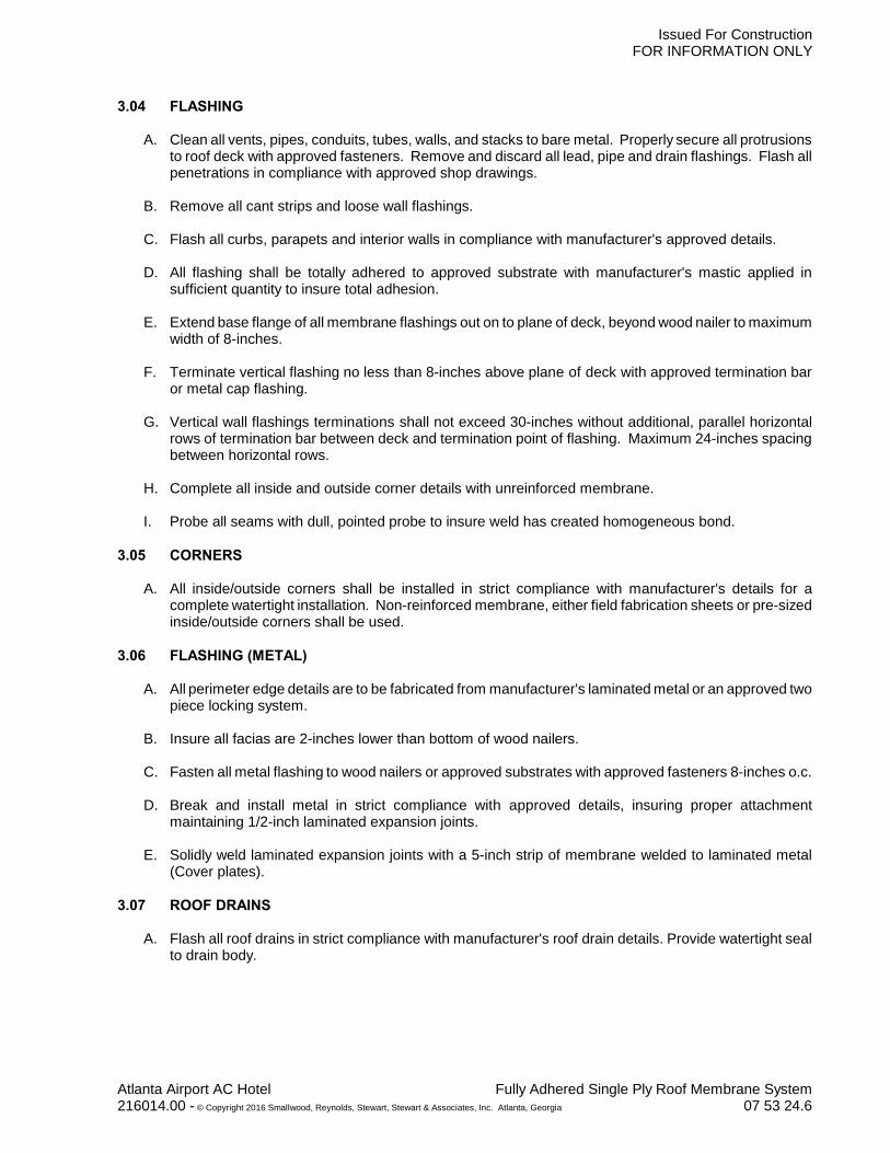
3.04 FLASHING
A. Clean all vents, pipes, conduits, tubes, walls, and stacks to bare metal. Properly secure all protrusionsto roof deck with approved fasteners. Remove and discard all lead, pipe and drain flashings. Flash allpenetrations in compliance with approved shop drawings.
B. Remove all cant strips and loose wall flashings.
C. Flash all curbs, parapets and interior walls in compliance with manufacturer's approved details.
D. All flashing shall be totally adhered to approved substrate with manufacturer's mastic applied insufficient quantity to insure total adhesion.
E. Extend base flange of all membrane flashings out on to plane of deck, beyond wood nailer to maximumwidth of 8-inches.
F. Terminate vertical flashing no less than 8-inches above plane of deck with approved termination baror metal cap flashing.
G. Vertical wall flashings terminations shall not exceed 30-inches without additional, parallel horizontalrows of termination bar between deck and termination point of flashing. Maximum 24-inches spacingbetween horizontal rows.
H. Complete all inside and outside corner details with unreinforced membrane.
I. Probe all seams with dull, pointed probe to insure weld has created homogeneous bond.
3.05 CORNERS
A. All inside/outside corners shall be installed in strict compliance with manufacturer's details for acomplete watertight installation. Non-reinforced membrane, either field fabrication sheets or pre-sizedinside/outside corners shall be used.
3.06 FLASHING (METAL)
A. All perimeter edge details are to be fabricated from manufacturer's laminated metal or an approved twopiece locking system.
B. Insure all facias are 2-inches lower than bottom of wood nailers.
C. Fasten all metal flashing to wood nailers or approved substrates with approved fasteners 8-inches o.c.
D. Break and install metal in strict compliance with approved details, insuring proper attachmentmaintaining 1/2-inch laminated expansion joints.
E. Solidly weld laminated expansion joints with a 5-inch strip of membrane welded to laminated metal(Cover plates).
3.07 ROOF DRAINS
A. Flash all roof drains in strict compliance with manufacturer's roof drain details. Provide watertight sealto drain body.
Atlanta Airport AC Hotel Fully Adhered Single Ply Roof Membrane System216014.00 - © Copyright 2016 Smallwood, Reynolds, Stewart, Stewart & Associates, Inc. Atlanta, Georgia 07 53 24.6

Issued For ConstructionFOR INFORMATION ONLY
3.08 TEMPORARY SEALS
A. At the end of each working day or at the sign of rain, install temporary watertight seal where theexposed edge of the completed new roofing terminates at the uncovered deck. Use a sufficient sizestrip of membrane or tape to bridge the new membrane and the roof deck. If using roofing membrane,strip must be welded to new roofing membrane and cemented to cleaned roof deck.
B. Prior to the commencement of work, remove all temporary seals if they will cause a water dam and allexposed roof cement if used. Do not track roof cements onto roof membrane.
3.09 FIELD QUALITY CONTROL
A. Initiate daily inspections of all completed work which shall include, but is not limited to, probing of all fieldwelding with dull pointed instrument to assure quality of application and insure that all equipment oroperator deficiencies are immediately resolved.
B. Insure that all aspects of installation (sheet layout, attachment, welding, flashing details, etc.) are instrict conformance with manufacturer's most current specifications and details.
C. Excessive patching of field seams because of inexperienced or poor workmanship or damage will notbe accepted at time of Final Inspection For Warranty.
D. All deviations from specifications and/or details requires written approval from manufacturer's technicalservice department prior to application to avoid warranty disqualifications.
E. Upon completion of roof membrane system installation, an inspection shall be made by representativeof roofing manufacturer to ascertain that roof membrane system has been installed in compliance withmanufacturerUs published specifications and details. Defects or deviations from manufacturerUs productdata and approved shop drawings shall be remedied as required to secure manufacturerUs warranty.
3.10 CLEAN-UP
A. Remove all debris and excess material from roof area. Pick up all loose fasteners and sheet metalscraps.
B. Insure watertightness of entire system for warranty inspection.
3.11 ADJUSTMENT AND REPAIRS
A. Perform repairs to membrane in compliance with manufacturerUs written recommendations.
B. Repair material shall be same material and same thickness as membrane being repaired.
C. Repair wrinkles within 18-inches of a seam, splice or puncture.
D. Repair membrane piece shall have rounded corners, extend minimum 3-inches beyond boundary ofseam, splice or puncture in all directions, and be minimum 6-inches x 6-inches in size.
E. Surface repairs in 10 foot x 100 foot area shall not exceed three. After performing individual surfacerepairs, overlay patched areas with new single sheet same width as original sheet running with theseams and extending minimum 6-inches past repairs in both directions.
3.12 PROTECTION
A. Do not permit transporting of heavy equipment and materials across completed roofing unless adequateprovisions are made to prevent damage to roofing.
Atlanta Airport AC Hotel Fully Adhered Single Ply Roof Membrane System216014.00 - © Copyright 2016 Smallwood, Reynolds, Stewart, Stewart & Associates, Inc. Atlanta, Georgia 07 53 24.7

Issued For ConstructionFOR INFORMATION ONLY
B. Protection:1. Protect building from damage and defacing by roofing operations.2. Restore or replace adjacent work or materials damaged during handling of roofing materials.
C. Provide temporary walkways over roofing wherever workmen must cross completed roofing until allother work on roof is completed.
END OF SECTION
Atlanta Airport AC Hotel Fully Adhered Single Ply Roof Membrane System216014.00 - © Copyright 2016 Smallwood, Reynolds, Stewart, Stewart & Associates, Inc. Atlanta, Georgia 07 53 24.8

Call To Order (888) 647-02002705 Mount Joy Road, Manheim, PA 17545 | Fax: (717) 653-5874
www.AandMhardware.com
Black 909-58
White 933-58
Gray 961-58
Almond 920-58
Formica color matches:
CONCEALED BRACKETS
Concealed Brackets with 9” to 30” Support ArmMounting Hardware Included - ( 3/8” - 16 x 3” carriage bolt assemblies )
2 - 58/ea 60+/ea
Bracket Size USA Import USA Import Pcs/Wgt/Box*
C - 9” $27.85 $21.85 $26.45 $20.35 2 pcs/11 lbs
C - 12” $29.85 $23.45 $28.35 $21.95 2 pcs/12 lbs
C - 18” $35.05 $29.05 $33.30 $27.55 2 pcs/18 lbs
C - 24” $39.95 $31.85 $37.95 $30.35 2 pcs/22 lbs
C - 30” n/a $33.35 n/a $31.70 2 pcs/27 lbs
Extended Concealed Brackets with 9” to 30” Support ArmMounting Hardware Included - ( 3/8” - 16 x 3” carriage bolt assemblies )
Bracket Size 2 - 58/ea 60+/ea Pcs/Wgt/Box*
EC - 9” $24.10 $22.60 2 pcs/14 lbs
EC - 12” $25.80 $24.30 2 pcs/16 lbs
EC - 18” $31.50 $30.00 2 pcs/22 lbs
EC - 24” $35.20 $33.70 2 pcs/24 lbs
EC - 30” $47.05 $44.70 2 pcs/31 lbs


Atlanta Airport AC Hotel
216014.00 Irrigation System
32 80 00
SECTION 328000
IRRIGATION SYSTEM
PART 1 - GENERAL
1.1 SECTION INCLUDES
A. This section includes requirements and specifications for irrigation system pipe,
fittings, valves, sprinklers, and automatic controls. Confirm available pressure.
1.2 SUBMITTALS
A. Product Data: Submit manufacturer’s product data and installation instructions for each
material and product used.
B. Shop Drawings: Submit shop drawings indicating sizing of pipe, material
characteristics, details of construction, connections, layout, relationship with adjacent
construction, wiring diagrams, and zoning chart.
C. Operation and Maintenance Data: Submit manufacturer’s operation and maintenance
data, including operating instructions, list of spare parts supplied, and recommended
and maintenance schedule.
D. Record Drawings and Instructions
1. Upon completion of installation, furnish record drawings showing all sprinkler
heads, valves, drains, and pipelines to scale with dimensions. These drawings
shall have dimensions from easily located stationary points as they relate to all
valves, mainlines, and wire. Clearly note all size, material, etc. Complete, concise
instruction sheets and parts lists covering all operating equipment and weathering
techniques shall be bound into folders and furnished to the UPS Project Engineer
in three copies.
1.3 QUALITY ASSURANCE
A. Comply with governing codes and regulations. Provide products of acceptable
manufacturers that have been in satisfactory use in similar service for three years. Use
experienced installers. Deliver, handle, and store materials in accordance with
manufacturer’s instructions.
B. Water Coverage for Turf Areas: 100 % of Area identified on plan
C. Water Coverage for Planting Areas: 100 % of Area identified on plan
D. Testing: Hydrostatic test at 1.5 times the operating pressure or 100 psi minimum.
E. Prior to backfilling, test system for leakage.
F. Adjustment of the sprinkler heads and automatic equipment will be done by the
Contractor upon completion of installation to provide optimum performance.

Atlanta Airport AC Hotel
216014.00 Irrigation System
32 80 00
1.4 REFERENCE STANDARDS
A. ASTM D 1785 – Standard Specification for Poly(Vinyl Chloride) (PVC) Plastic Pipe,
Schedules 40, 80, and 120; current edition.
B. ASTM D 2464 – Standard Specification for Threaded Poly(Vinyl Chloride) (PVC)
Plastic Pipe Fittings, Schedule 80; current edition.
C. ASTM D 2467 – Standard Specification for Poly(Vinyl Chloride) (PVC) Plastic Pipe
Fittings, Schedule 80; current edition.
1.5 PERFORMANCE STANDARDS
A. Irrigation zone control shall be automatic operation with controller and automatic
control valves.
B. Location of Sprinklers and Specialties: Shall be design by sprinkler installer. Design
location is approximate. Make minor adjustments necessary to avoid plantings and
obstructions such as signs and light standards. Maintain 100 percent irrigation
coverage of areas indicated.
C. Delegated Design: Design 100 percent coverage irrigation system, including
comprehensive engineering analysis by a qualified professional engineer, using
performance requirements and design criteria indicated.
D. Minimum Working Pressures: The following are minimum pressure requirements for
piping, valves, and specialties unless otherwise indicated:
1. Irrigation Main Piping: 200 psig (1380 kPa).
2. Circuit Piping: 150 psig (1035 kPa)
PART 2 - PRODUCTS
2.1 MATERIALS
A. Pressure Piping: PVC plastic, ASTM D 1785, Schedule 80 pipe; ASTM D 2467
Schedule 80 socket-type PVC plastic pipe fittings; solvent-cemented joints.
B. Branches and Offsets at Sprinklers and Devices: PVC plastic, ASTM D 1785,
Schedule 80 pipe with threaded ends; ASTM D 2464, Schedule 80, PVC plastic
threaded fittings; threaded joints.
C. Valves with Cast Bronze Bodies:
1. Manual Circuit Valves: Globe valves.
2. Key-Operated Valves: Manual valves fitted for key operation.
3. Automatic Circuit Valves: Globe valves solenoid operated.
4. Automatic Drain Valves: Automatic opening when pressure is below 3 psi.
D. Backflow Preventer: Cast bronze.
E. Sprinklers:
1. Flush surface type with fixed pattern.

Atlanta Airport AC Hotel
216014.00 Irrigation System
32 80 00
2. Bubbler type with fixed pattern.
3. Shrubbery type with fixed pattern.
4. Pop-up spray type with fixed pattern.
5. Pop-up rotary spray type, gear drive.
6. Pop-up rotary impact type, impact drive.
7. Above-ground rotary impact type, impact drive.
F. Valve Box: Precast concrete with cast iron, lockable valve cover and frame.
G. Automatic Control System:
1. Interior control enclosure.
2. Low-voltage transformer.
3. Circuit control.
4. Timing device.
5. Rain-compensating device.
PART 3 - EXECUTION
3.1 INSTALLATION
A. Protect existing landscaping from damage. Repair and repave paving cut to run
irrigation lines to match paving in original condition.
B. Install materials and systems in accordance with manufacturer’s instructions and
approved submittals. Install materials and systems in proper relation with adjacent
construction. Coordinate with work of other sections.
C. Restore damaged components and test for proper operation. Clean out system and
protect work from damage.
D. Instruct Owner’s personnel in proper operation and maintenance procedures.
E. Install all supply lines in sleeves under all paving.
F. Trenching:
1. Dig trenches straight and support pipe continuously on bottom of trench. Lay pipe
to an even grade. Follow layout indicated on drawings.
2. Coverage: 18 inches for pressure supply lines; 12 inches for non-pressure lines;
and 18 inches for control wiring.
END OF SECTION

