ac-dc interaction - usaid sari/energy integration · ac/dc system strength voltage stability...
TRANSCRIPT

AC- DC Interaction
AC- DC Interaction
� AC/DC System interactions are concerned with
- Voltage stability
- Over voltages
- Resonances
- Recovery from disturbances

AC/DC System Strength
� Voltage stability conditions determines the type of voltage
control and the type of reactive power supply.
� The level of Temporary Overvoltage influences station design,
including thyristor valve and surge arrester ratings.
� The larger the ratio of shunt capacitor Mvar to ac system short
circuit MVA, the lower is the resonance frequency.

An AC System Can Be Defined As “Weak” From Two Aspects…
� AC system impedance may be high relative to dc power at the point of
connection.
� AC system mechanical inertia may be inadequate relative to the dc
power infeed.

Short Circuit Ratio (SCR)
� SCR is an indicator used to characterize the strength of the
power system.
SCR = S/Pd
Where ‘S’ is AC system three phase short circuit level in MVA at
the Converter Terminal AC Bus with 1.0 pu AC Terminal
Voltage, and Pd is the rated DC power in MW.
� The minimum value of ‘S’ at which the rated power Pd is
transmitted is used when examining limiting operating
conditions.

� A High SCR AC/DC System – SCR>3
� A Low SCR AC/DC System - 2<SCR<3
� A Very Low SCR AC/DC System – SCR<2
A scheme may be operating with High SCR for most of the time,
but it may appear as Low or Very Low SCR scheme during
emergency, at ac system outage conditions.
In such cases the scheme must be designed to operate for those
conditions, unless DC power reduction is acceptable.
Short Circuit Ratio (SCR)

Effective Short Circuit Ratio (ESCR)
Shunt capacitors including ac filters connected at the ac terminal of a
DC link can significantly increase the effective AC system impedance.
ESCR = (S-Qc)/Pd
Where Qc is the value of three phase fundamental Mvar in per unit of Pd
at per unit AC Voltage of Shunt Capacitors connected to the Converter
AC Bus Bar.

Inadequate and Zero Mechanical Inertia
� Turbine – generators in an ac system represent a large rotating mass.
Their inertia ensures that an ac system does not collapse due to
system fault.
� If all the power is brought into a system by DC and there is no local
generator, then that system will have no mechanical inertia.
� To avoid frequency reduction by more than 5% due to a system fault,
the effective DC Inertia Constant, Hdc should be greater than 2s.

Harmonic Transfer
� A DC Convertor appears substantially a source of harmonic current.
It act as a constant current source on ac side and constant voltage
source on dc side.
� The effective impedance in which this harmonic current flows is that
of the complete system.
� Weak system may cause Core saturation Instability in the Convertor
Transformer and Complementary Resonances.
� Back-to-back schemes are probably most at risk than long DC
Transmission lines and Cable Systems.

Temporary Overvoltages
Larger disturbances result in temporary overvoltages and if resonance
conditions in the ac network are close to one of the lower order
harmonics, the overvoltage can be amplified. This is often the case
with weak system.
Temporary overvoltages influence the design of arresters connected to
ac and dc side.
Shunt capacitors and AC filters in DC station decrease the SCR on the
bus bar and influencing TOV. TOV can be reduced by using Metal
oxide gapless arrester and by switching of capacitors banks and ac
filters.

Effect of AC System strength on Commutation failures
� Due to weak ac system connected to inverter , Commutation failure may
occur on inverter side.
� Recovery after faults is usually easier with a high SCR than a very Low SCR
system.
� Post fault system swings and voltage instability at the inverter bus of certain
weak system may cause subsequent commutation failures. In these cases,
slow rate of dc recovery is desirable and must be optimized.

Subsynchronous Torsional Interaction Between DC Convertors And Nearby Turbine Generators
Torsional Interaction:
� All phenomena related to interactions between the electrical power system and turbine/generator torsional mechanical modes of oscillation.

Torsional Interaction phenomena can be split into three main categories:
1. SSR = Subsynchronous Resonance:
Resonance condition between torsional mode(s) of Turbine
/Generator shaft and a natural frequency of the electrical power
system.
SSR can occur when series compensation is used the power
system.
2. SSO = Subsynchronous Oscillations:
(also known as DDSO = Device dependent subsynchronous
Oscillations)
Category of interaction between generator torsional system and
power system components and power control system.

Torsional Interaction phenomena can be split into three main categories:
3. SSTI = Subsynchronous Torsional Interaction:
Type of DDSO which occurs between thermal generators and controls of large power Electronic Devices (e.g. HVDC) in the power system.
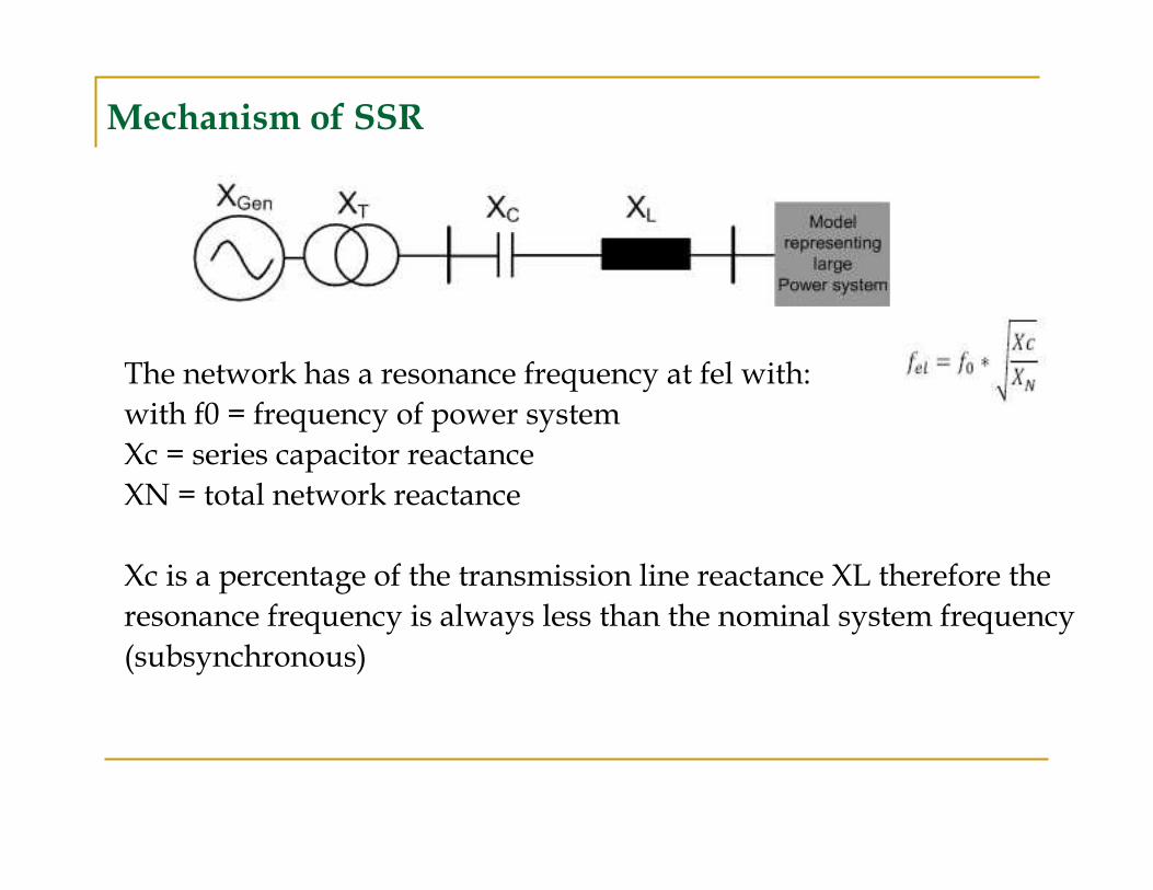
Mechanism of SSR
The network has a resonance frequency at fel with:
with f0 = frequency of power system
Xc = series capacitor reactance
XN = total network reactance
Xc is a percentage of the transmission line reactance XL therefore the
resonance frequency is always less than the nominal system frequency
(subsynchronous)

� There exists a resonance in the ac system at fel< f0(for example as a
result of a series capacitor) and a mechanical resonance of the shaft
at (f0 -fel= fmech).
� Excitation of the system.
� Currents of the frequency fel in the AC system are excited.
� In the rotor currents of the frequency f0 ±fel are induced (f0-
fel=fmech).These currents lead to an oscillation of the
generator/turbine shaft.
� The terminal voltage contains the frequencies f0±fmech(f0-
fmec=fel)
� There exists a feedback loop. If the phase shift is unfavorable
positive feedback can occur instability of the torsional oscillation
Mechanism of SSR
Mechanism of SSTI
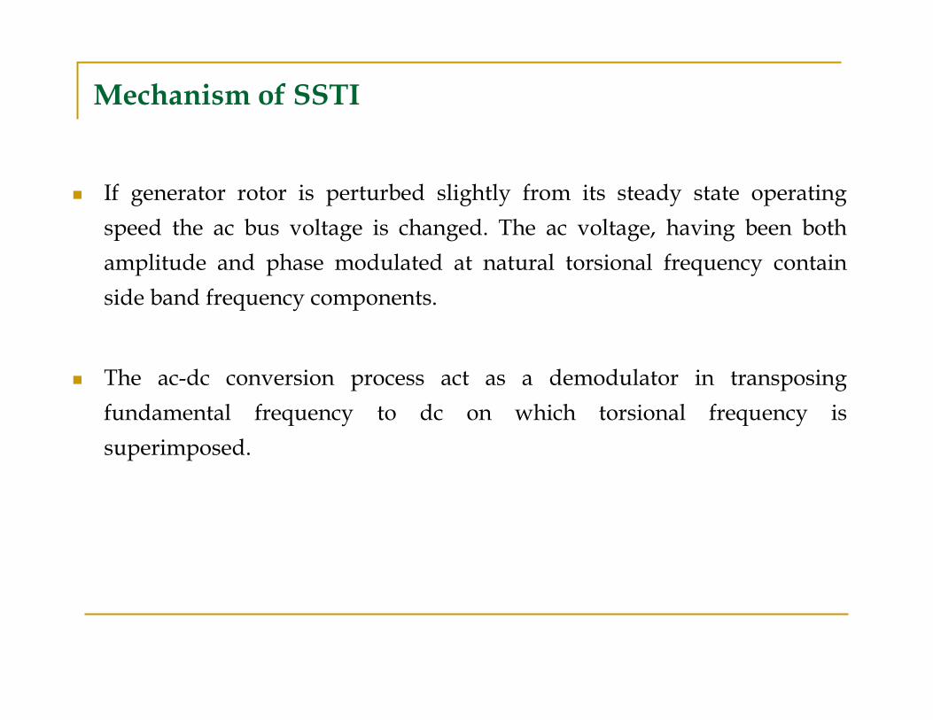
� If generator rotor is perturbed slightly from its steady state operating
speed the ac bus voltage is changed. The ac voltage, having been both
amplitude and phase modulated at natural torsional frequency contain
side band frequency components.
� The ac-dc conversion process act as a demodulator in transposing
fundamental frequency to dc on which torsional frequency is
superimposed.

� In current control mode torsional frequency component on DC current
appears as a control error in dc current regulator feedback loop and
produces corresponding change in firing angle and hence AC current at
the same frequency.
� This change in current produce a change in generator electrical torque.
The increasing speed perturbations cause torsional vibrations in the
shaft structure of the generator leading to torsional stresses and fatigue
of the shaft.
Mechanism of SSTI
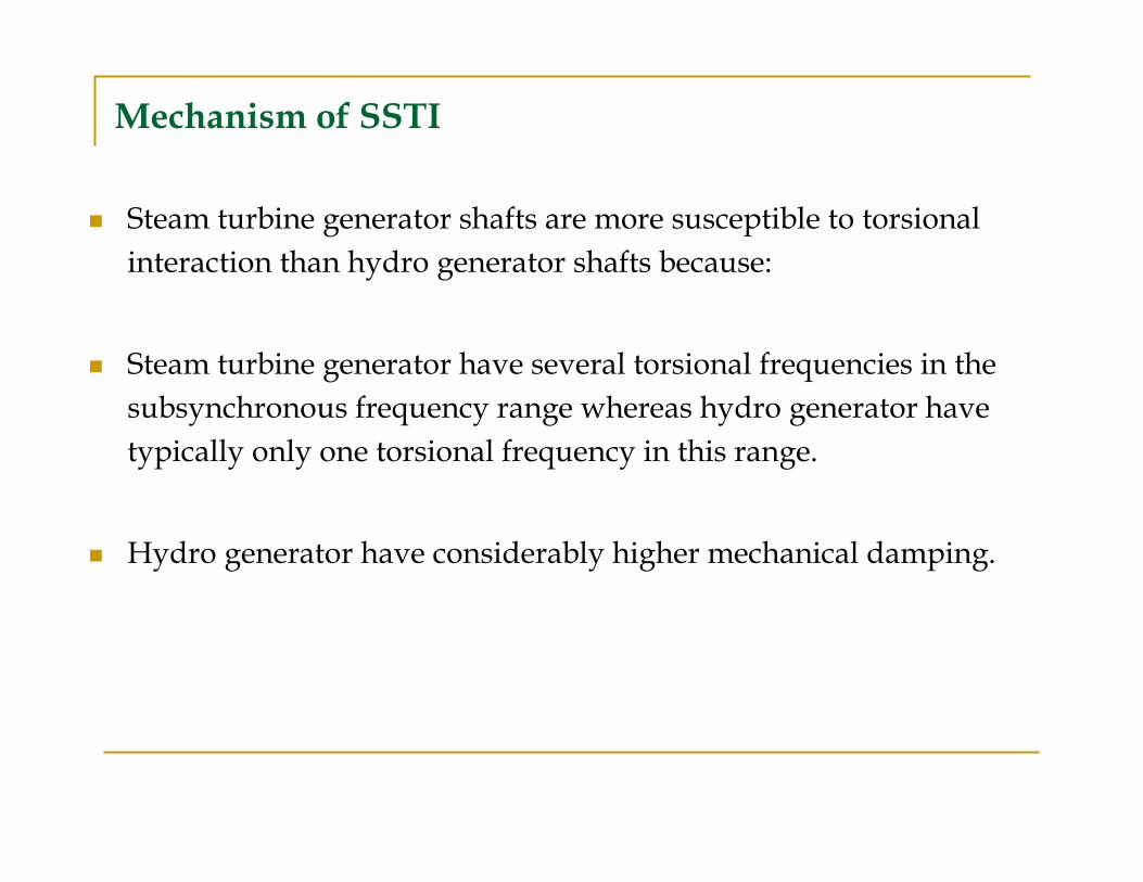
� Steam turbine generator shafts are more susceptible to torsional
interaction than hydro generator shafts because:
� Steam turbine generator have several torsional frequencies in the
subsynchronous frequency range whereas hydro generator have
typically only one torsional frequency in this range.
� Hydro generator have considerably higher mechanical damping.
Mechanism of SSTI

� It has found that generating units near a rectifier terminal are vulnerable to
torsional interactions.
� The units near an inverter terminal do not experience much disturbances.
� The transfer of harmonics from one end of the dc link to other end may
possibly result in steady state oscillations that could excite torsional modes
nearby turbine-generators.
Factors Affecting Torsional Stresses

� The current and power control of an HVDC link is the main reason for
negative electrical damping.
� Negative damping can increase when the firing angle of the HVDC link
increases.
� The interaction between a generator and HVDC convertor depends on
electrical distance between them.
Factors Affecting Torsional Stresses

Based on the results of the EPRI research project, the influence of dc
control on torsional damping of a particular generator can be quantified
by Unit Interaction Factor (UIF) as:
Method of Investigation…

Where:
UIFi = Unit Interaction factor of the generator
MVAHVDC = Rating of DC system
MVAi = Rating of generator
SCi = Short circuit capacity at the dc commutating bus excluding the generator
SC Tot = Short circuit capacity at the dc commutating bus including the generator
Method of Investigation…

� For unit interaction factor less than 0.1, there is very little interaction
between the dc controls and the turbine generator torsional
oscillations.
� Larger values of UIF may need detailed studies an corrective action
in the HVDC system.
Method of Investigation…

Solutions to prevent Torsional Stresses
� HVDC control system implemented with supplementary stabilizing
control called Sub synchronous Supplementary damping Control
(SSDC), which is sensitive to shaft motion of electrically close generators
and which adds sufficient damping to permit operation in a system
condition which would otherwise be unstable.
� Generators that have any risk of torsional interactions, with HVDC links
or other devices, equipped with protections (alarm and trip)

THANK YOU