abstracts and short papers table of contents web page/nsf workshop 2005... · ·...
TRANSCRIPT

ABSTRACTS AND SHORT PAPERS Table of contents
Author
Presentation Page
Arul K. Arulmoli Nonlinear Modeling of Dynamic Soil-Structure Interaction: A Practitioner’s Viewpoint
3
Fusao Oka A Thermo-Hydro-Mechanically Coupled Analysis Of Clay Using A Thermo-Elasto-Viscoplastic Model
4
Ioannis Vardoulakis and Antonis Zervos
Numerical Modelling Using Gradient Elasticity And Plasticity
5
V. N. Kaliakin Nonlinear Modeling of Geotechnical Problems: Bridging the Chasm Between Theory and Practice
9
Ronaldo I. Borja Stability and uniqueness of solutions and their implications to nonlinear modeling
10
Chandrakant S. Desai Nonlinear And Constitutive Modeling In Geotechnical Engineering: Fundamentals Through Application
12
K.L. Fishman Geotechnical Engineering Practice: Changing the Paradigm
19
K.K. (Muralee) Muraleetharan
A Comprehensive Approach to Modeling the Behavior of Unsaturated Soils Using an Elastoplastic Framework
26
A.P.S. Selvadurai Thermo-Hydro-Mechanical Effects In Fluid-Saturated Poroelastic Geomaterials
28
Richard Wan On the Microstructural Aspects of Granular Material Behaviour
33
X.S. Li Continuum framework for three-phase soil including microstructural effects
35
Cino Viggiani A Key Issue In Small Strain Modeling: Capturing The Dependence Of Soil Response On The Direction Of Loading
37
Thomas Meier Some Important Aspects of the Mechanical Behaviour of Soils under Cyclic Loading
39
Majid T. Manzari Significance of Modeling Dilatancy in Geomechanics 41
J. Ghaboussi and Y. M. Hashash
Soft Computing Approaches to Constitutive Modeling in Geotechnical Engineering
42
David Muir Wood Nonlinear Modelling Of Soils 43
Ning Lu Unified Effective Stress Concept for Unsaturated Soils 49

Pedro Arduino Two-Surface Soil Constitutive Model Calibration For Coarse Granular Materials
50
Tomasz Hueckel Mathematical Models for Geo-Engineering Practice: Big Projects and Constitutive Parameters are the Key
52
Rajah Anandarajah Sliding/Rolling Constitutive Model and Its Generalization
57
D.V. Griffiths Probabilistic analysis by the random Finite Element Method: A more rational approach to decision making in geotechnical analysis and design
58
Roberto Nova An Elasto-Plastic Model for Soft Geomaterials
60
Boris Jeremić
Modeling and Simulations for Geotechnical Problems
65
Laureano R. Hoyos
Paul W. Mayne
Siva Kesavan
Yannis F. Dafalias
Rich Regueiro
Richard J. Finno
Craig H. Benson
Conrad Felice
Experimental and Computational Modeling of Unsaturated Soil Response Under True Triaxial Stress States Need for Integrated Interpretation of In-Situ Tests Modeling Embankment Induced Lateral Loads on Deep Foundations From Theory to Practice in Geotechnical Engineering: The Missing Links Mesh-independent Finite Element Modeling of Three-dimensional Localized Failure Mechanisms in Saturated and Partially-Saturated Geomaterials Using Field Observations to Calibrate Constitutive Models Complicating Factors When Modeling Unsaturated Flow At the Near Surface State of Numerical Modeling in Practice: One Practitioners View
69
71 74 75 82 87 92
95
Debra F. Laefer, Anne Crowley and Pu Jiang
Modeling Microcrystaline Wax for Seismic Protection of Art Objects
102

Nonlinear Modeling of Dynamic Soil-Structure Interaction:
A Practitioner’s Viewpoint
Arul K. Arulmoli
Earth Mechanics, Inc., Fountain Valley CA, USA
Abstract During the past decades, significant advancements have been made in the area of constitutive modeling of soils and a number of computer programs have been developed that are capable of modeling non-linear behavior of static and dynamic geotechnical problems. Some of these computer programs are also capable of evaluating dynamic soil-structure interaction problems. Due to the availability of faster and cheaper microcomputers, use of these computer programs for soil-structure interaction evaluations has become somewhat more affordable making it possible to incorporate these analyses into larger projects. However, routine use of these computer programs by practicing geotechnical engineers has been significantly lagging the advancements made by the research community. Practicing geotechnical engineers are faced with challenges from different fronts including limited budgets and demanding schedules; clients, owners, and reviewers who are not well-informed about the benefits of advanced computer programs or who are unwilling to accept tools or methodologies that have not been proven in the industry; and geotechnical engineers themselves who are not aware of or do not understand many of the available tools/methodologies. Other challenges include practical and economical determination of parameters for constitutive models; practical calibration/verification of analytical models for problems similar to those analyzed; and proper representation of boundary conditions, especially for dynamic problems. Therefore, geotechnical engineers often tend to rely on simplified approaches and simple constitutive models to evaluate dynamic soil-structure interaction problems. When addressing dynamic soil-structure interaction problems, geotechnical engineers face an additional challenge of understanding the structural design implications of the geotechnical design recommendations since these recommendations are primarily used by structural engineers. Even when advance computer programs are used by geotechnical engineers, the lack of clear understanding of structural engineers’ needs typically results in geotechnical reports that have limited use for structural engineers. Efforts should be focused on overcoming these challenges through effective collaboration between researchers and practitioners in geotechnical and structural disciplines so that the capabilities and limitations of advanced computer programs for dynamic soil-structure interaction problems are better understood by both disciplines.
3

A Thermo-Hydro-Mechanically Coupled Analysis Of Clay
Using A Thermo-Elasto-Viscoplastic Model
Fusao Oka
Kyoto University, Japan
4

Numerical Modelling Using Gradient Elasticity And Plasticity
Ioannis Vardoulakis
National Technical University of Athens, Greece
Antonis Zervos
University of Southampton, United Kingdom
Abstract There is ample experimental evidence that shear-bands in granular materials engage a significant number of grains. Starting with Roscoe (1970) experimental observations suggest that the width of shear-bands is a small multiple of grain diameter (Scarpelli & Wood 1982, Vardoulakis & Graf 1985, Oda & Kazama 1998, Alshibli & Sture 1999). In order to be able to predict theoretically the dimensions of the shear-band, the grain size must be introduced into the constitutive model. Thus, in order to trace the deformation in the post-bifurcation regime one has to account for the microstructure of the material by resorting to the so-called higher-order continuum theories like the Cosserat Continuum Theory. This idea was widely publicized by the paper Mühlhaus & Vardoulakis (1987) and has meanwhile matured in a variety of large scale numerical simulations, which account for higher continuum effects (Papanastasiou & Vardoulakis 1992, Oka et al. 2000, Zervos et al. 2001a & b, Chambon et al., 2001 & 2004, Matsushima et al. 2002, Pamin et al. 2003, Simone et al. 2004, Manzari & Regueiro 2005). The aim of this paper is to describe a numerical procedure for modelling deformation localisation. This procedure is a natural extension of the mainstream elastoplastic numerical framework widely used in engineering practice, and is based on the finite element method as applied to elliptic and almost hyperbolic problems The constitutive frameworks that will be employed here are extensions of elasticity and elastoplasticity, which include assumptions about the material microstructure through the definition of material parameters with the dimension of length. These extensions allow the rescaling of the problem, so as to account for boundary layers and finite-thickness shear-bands. The introduction of these material length parameters has important implications for the nature of the constitutive quantities and of the boundary conditions. In particular, new types of stress-like quantities, like couple stresses and double stresses, need to be introduced. Similarly, new kinds of boundary conditions are needed, leading to the introduction of generalised forces. The “physical” meaning of these additional stress-like quantities and boundary conditions is elaborated with reference to the Theory of Structures, and their advantages for engineering practice are explained.
5

It is shown that the proposed numerical procedure, in conjunction with the above constitutive approach, allows robust modelling of a range of localisation phenomena, including details of the failure mechanism and of the related scale effects. For example considering the shear failure of an externally pressurised borehole (Fig. 1), we retrieve both the observed failure pattern and scale effect.
Figure 1. Robust post-failure shear-banding computations and prediction of scale
effect, using a 2nd gradient plasticity F.E. model (Zervos et al. 2001b). References Alshibli, KA and Sture, S, (1999). Sand shear band thickness measurements by digital imaging techniques Journal of Computing in Civil Engineering, 13:103-109 Chambon R, Caillerie D, Matsuchima T, (2001). Plastic continuum with micro structure, local second gradient theories for geomaterials: localization studies, Int J Solids Structures, 38:8503-8527 Chambon R, Caillerie D, Tamagnini C, (2004). A strain space gradient plasticity theory for finite strain, Computer Methods in Applied Mechanics and Engineering, 193:2797-2826 Manzari MT, Regueiro RA (2005).Gradient plasticity modeling of geomaterials in a meshfree environment. Part I: Theory and variational formulation, Mechanics Research Communications, 32:536-546 Matsushima T, Chambon R, Caillerie D (2002). Large strain finite element analysis of a local second gradient model: application to localization, Int J Num Meth Engng, 54:499-521
6

Mindlin, R.D. and Eshel, N.N. (1968). On first gradient theories in linear elasticity. Int. J. Solids Structures, 4, 109-124 Mühlhaus, H-B. and Vardoulakis, I. (1987). The thickness of shear bands in granular materials, Geotechnique, 37:271-283 Oda, M and Kazama, H, (1998). Microstructure of shear bands and its relation to the mechanisms of dilatancy and failure of dense granular soils, Geotechnique, 48:465-481 Oka F, Yashima A, Sawada K, et al. (2000). Instability of gradient-dependent elastoviscoplastic model for clay and strain localization analysis, Computer Methods in Applied Mechanics and Engineering, 183: 67-86 Pamin J, Askes H, de Borst R (2003). Two gradient plasticity theories discretized with the element-free Galerkin method, Computer Methods in Applied Mechanics and Engineering, 19:2377-2403 Papanastasiou, P. and Vardoulakis, I. (1992). Numerical treatment of progressive localization in relation to borehole stability. Int. J. Num. Anal. Meth. Geomech., 16:389-424 Roscoe, KH (1970). The influence of strains in soil mechanics, Geotechnique, 20:129-170 Scarpelli, G. and Wood, D. M. (1982). Experimental observation of shear band patterns in direct shear tests. In: Deformation and Failure of Granular Materials, Balkema, 473-484 Simone A, Askes H, Peerlings RHJ, et al. (2004) Interpolation requirements for implicit gradient-enhanced continuum damage models, Communications in Numerical Methods in Engineering, 20:163-165 Vardoulakis, I. and Graf, B. (1985). Calibration of constitutive models for granular materials using data from biaxial experiments, Geotechnique, 35:299-317 Vardoulakis, I. (2004). Linear Micro-Elasticity. In: Degradations and Instabilities in Geomaterials, Darve, F. and Vardoulakis, I. (eds), Chapter 4, Springer. Vardoulakis, I. and Zervos, A. (in preparation). A finite element formulation of Micro-Elasticity. Zervos, A., Papanastasiou, P. and Vardoulakis, I., (2001) A finite element displacement formulation for gradient elastoplasticity, Int. J. Num. Meth. Engng, 50:1369-1388 Zervos, A., Papanastasiou, P. and Vardoulakis, I., (2001) Modelling of localisation and scale effect in thick-walled cylinders with gradient elastoplasticity, Int. J. Solids Structures, 38:5081-5095 Zervos, A., Papanastasiou, P. and Vardoulakis, I., (2001). Shear localisation in thick-walled cylinders under internal pressure based on gradient elastoplasticity, IUTAM Symposium on Analytical and Computational Fracture Mechanics of Non-homogeneous Materials,18-22 June 2001, University of Cardiff.
7

Modeling Microcrystaline Wax for Seismic Protection of Art
Objects
Debra F. Laefer
University College Dublin, Ireland
Anne Crowley
University College Dublin, Ireland
Pu Jiang
University College Dublin, Ireland
Abstract Recent work undertaken at the behest of the Getty Art Institute investigated the procedural development for using microcrystalline waxes for the protection of art objects against earthquake-induced movements. The initial stage of this research encompassed the development of testing techniques for static tensile and shear tests. The results of these tests showed a highly complex set of failure mechanisms both at the wax/object interface and within the body of the wax itself. The second stage of testing will include dynamic material tests and limited shake table experiments. Because of the nearly infinite range of shapes, sizes, weights, and centers of gravity for art objects, it is anticipated that being able to use finite element modeling will be critical to providing sufficient guidance as to the quantity of wax that needs to be applied for protection of any particular object. The main challenge surrounding this is selection and implementation of an appropriate non-linear model.
8

Nonlinear Modeling of Geotechnical Problems:
Bridging the Chasm Between Theory and Practice
V. N. Kaliakin Department of Civil & Environmental Engineering, University of Delaware, Newark
DE, USA Abstract The development of advanced constitutive models for geomaterials and their implementation into computer programs has been a mature area of research for over thirty years. Yet the use of such models and programs by practitioners to simulate geotechnical problems has been surprisingly limited. Compared to other Civil Engineering specializations, as well as to other engineering disciplines such as Biomedical, Electrical, Aerospace, etc., this disparity is quite stark indeed. This paper investigates potential reasons for the aforementioned chasm between theoretical and numerical developments and their use by practicing engineers. It is shown that the complex particulate nature of geomaterials alone cannot be responsible for this chasm. This is followed by a brief discussion of action that needs to be taken to bring theoretical and numerical developments closer to the hands of the practitioners. This includes appropriate academic training, education in the capabilities and limitations of constitutive models, and the understanding of model parameters and the procedure used to determine their values. Of equal importance is the availability of databases of model parameter values that will hopefully facilitate the use of advanced constitutive models by practicing engineers.
9

Stability and uniqueness of solutions and their implications to
nonlinear modeling
Ronaldo I. Borja
Department of Civil and Environmental Engineering, Stanford University, Stanford CA, USA
Abstract Nonlinear models in geotechnical engineering are aimed at predicting deformation, stresses, and onset of failure. A common mistake committed by the modeler is to push the limit of validity of a model in the regime where it is not applicable. For example, nonlinear models developed and calibrated in the pre-failure regime are sometimes used for post-failure response predictions. This could lead to non-uniqueness of the solution and the failure of an iterative strategy to converge, oftentimes frustrating the user. Stable solutions are commonly associated with the hardening branch of the load-deformation response. When loaded further the response typically reaches a plateau, then is followed by a negative slope as the strength of the structure degrades. Somewhere near the plateau the stress state permits branching of the mechanical response into a number of possible load paths. This is commonly called the bifurcation point. Bifurcation can take place in a number of ways. For a solid continuum bifurcation can produce either a diffuse or localized mode, and can be triggered by either material and/or geometric nonlinearity along with even the most minute imperfection. It is not possible to consider all possible post-bifurcation responses because there is an infinite number of them. However, it is possible to select one of these modes and track its evolution during the course of the solution. For example, we can investigate the post-bifurcation response into a shear band by selecting a specific shear band and following its evolution. Although this provides only one solution among an infinite number of other possible solutions, it makes the modeling that much more meaningful because we clearly recognize that there could be other possible solutions and we are only following one of them. In contrast, ignoring the possible non-uniqueness of the solution altogether could result in disaster. Not only are we beset with a result that exhibits pathological mesh dependence, but the user might even believe that this result is credible and use it for designing real engineering structures. How then do we determine the limit of stable region in the analysis of typical nonlinear boundary-value problems? In this paper we consider various jumps in the strain rate tensor to investigate the existence of other possible solutions. Bifurcation modes considered include strain rate jumps of tensors of ranks one and higher
10

corresponding to deformation bands and diffuse instabilities, respectively. Eigenmodes are extracted for each type of instability to fully characterize various frameworks of deformation, including compaction banding for high-porosity rocks and volume implosion for collapsible (loose) granular soils.
11

Nonlinear And Constitutive Modeling In Geotechnical
Engineering: Fundamentals Through Application
Chandrakant S. Desai
Department of Civil Engineering and Engineering Mechanics, The University of
Arizona, Tucson, Arizona USA
INTRODUCTION Nonlinear modeling is essential for many geotechnical problems. Constitutive modeling of geomaterials and interfaces/joints, which is the integral and vital aspect for the nonlinear behavior, plays an important role. In the past, most engineering and geotechnical problems were solved approximately by adopting the linear behavior of the materials. Since nonlinear behavior is exhibited by most geomaterials, it was necessary to use ad hoc schemes and factors of safety to account for the nonlinear response. Over about the past three decades, significant research has occurred in geotechnical engineering to account for the nonlinear behavior. However, because of the nature and economics aspects of the problems in geotechnical engineering, and in general, civil engineering, there appears a wide gap between the adoption of the research results into practice. In comparison to other engineering disciplines such as electronics and computer engineering and aerospace engineering, the need for adopting the research results into practice is significantly delayed in geotechnical engineering. Often, the lack of appropriate education and knowledge of the topics associated with (advanced) research may add to the apprehension of advanced research, resulting in the delay. In spite of such delays, it must be noted that compared to about three decades ago, many research developments have entered into the geotechnical practice. For instance: (1) use of the critical state constitutive models, (2) numerical finite and boundary element methods for stress-deformation analysis of problems involving complexities that cannot be handled by the conventional procedures, like tunnels, piles, dams, and reinforced earth, earthquake analysis, and (3) seepage and stability. The use of such developments has been as alternative schemes for analysis, and very often they are used as secondary procedures in design and analysis. Indeed, nonlinear material and computer models can be considered the primary procedures for failure or forensic analysis. However, considerable gap still exists in applying research results in practice. Hence, it is essential to discuss and develop means to encourage prompter use of the research results for practical application.
12

As stated before, constitutive modeling is vital for nonlinear modeling. A unified model called the disturbed state concept (DSC) developed by the author and coworkers, that can be used for practical application, will be discussed here. FACTORS Since a main issue for nonlinear modeling is constitutive models for geomaterials; the latter are dependent on a number of factors of practical importance. The perceived complexity of constitutive models, numbers of parameters involved, tests for determination of parameters and need for validations are some of the factors that may hamper their use in practice. Factors influencing the practical behavior decide the so-called complexity. If the behavior of a soil is affected by irreversible deformations, volume change and stress paths, a linear or nonlinear (hyperbolic, parabolic, splines, etc.) model, although it may be termed as a “simple” model, cannot handle these effects. An enhanced model, even if it seems to be “complex,” is required. Complexity will depend on the number of factors that influence the actual behavior. If the material exhibits microcracking leading to degradation or softening, an enhanced model is required. Therefore, the objective should be development of “simplified” models to account for significant factors that influence the practical behavior. Then, the number of parameters will increase with the increasing enhancement. However, with special schemes such as systematic removal of less important factors and relating the parameters to specific states of deformation, the number of parameters can be reduced. Hence, the researchers should not only publish standard papers, but also try to attend to the need to explain how to apply the results in practice. For instance, practitioners can be made aware of the advantages and limitations of models by establishing the ranges of applications of the models, and the need of using them for specific factors governing the practical problem on hand. One of the items of concern for the practitioner is that the so-called complex or advanced model would consume more effort and time. However, they should be made aware that once a model is introduced in a computer program, only the computer time may be affected, not the effort and time for the user. Indeed, the practitioner would require additional time to obtain the parameters in the model. Even here, very often the number of parameters for the advanced models such as classical plasticity (e.g., Mohr-Coulomb), or yielding or hardening plasticity (e.g., critical state and HISS) are the same or lower than the nonlinear elastic model, which is considered to be “simple.” However, the advanced models can handle greater number of practical factors such as irreversible (plastic) deformations, volume change, stress path and directional dependence of the strength compared to the simple models.
13

The number of parameters for the nonlinear elastic hyperbolic models are about eight (c, φ, Rf, K, η1, G, F, d) (Duncan and Chang, 1970; Kulhawy, et al., 1969). The parameters required for the classical Mohr-Coulomb model are four (E, ν, c, φ), for the critical state model are six (E, ν, M, λ, κ, eo) (Desai and Siriwardane, 1984), and for the hierarchical single surface (HISS) plasticity model are about eight (E, ν, γ, β, n, R, a1, η1) (Desai 2001). However, the HISS model can account for plastic deformations, directional dependence of strength, volume change, dilation before peak, and stress path, which the nonlinear elastic and critical state model may not. Moreover, the parameters for the Mohr-Coulomb, critical state and HISS models can be defined on the basis of the same (triaxial) test data as used for the nonlinear elastic model. Hence, what is required is the education for the practitioner, by papers, reports and joint meetings between researchers and practitioners. Often, the funding agencies do not support proposals to transfer available research results to practice. It will be most useful if such proposals for technology transfer are supported actively, maybe by establishing special agencies for such technology transfer. One of the ways for the technology transfer can be the support of “sabbatical” periods with practitioners, for the academic and other persons involved in the development of material models. THE DISTURBED STATE CONCEPT (DSC) With the foregoing aim in mind, the author and coworkers have developed the disturbed state concept (DSC), which can account for the general, elasto-plastic-softening behavior of geological materials, and interfaces and joints. DSC is a unified and simplified approach which can be used to evolve models for behavior involving increasing factors, in a hierarchical manner. Details of the DSC are given in a number of references included in Desai (2001). Brief description and comments are presented here. In the DSC, the observed behavior (a) of a deforming material element is expressed in terms of the behavior of the RI or continuum part and that of the FA part, through the disturbance D, which allows for the coupling or interacting mechanism between the RI and FA part. If the material is initially in the fully continuum state, e.g., there are no cracks or discontinuities, the value of D = 0. As the material deforms, its microstructure changes, and microcracking and discontinuities occur. As the deformation progresses, D increases and tends to unity in the final stages of deformation. The basic incremental constitutive equations for the DSC are:
14
( )
( ic
cciia
dD
dCDdCDd
~~
~~~~~1
σσ
εεσ
−
++−=
) (1a)
or (1b) iDSCa dCd
~~~εσ =
where a, i, c denote observed, RI and FA behavior, respectively, = observed
stress, = stress in the relative intact (RI) part, = stress in the fully adjusted
(FA) part, = constitutive matrix for RI material, = constitutive matrix for the
FA material, dD = increment or rate of D, and a, i, c denote observed, RI and FA, respectively.
a
~σ
i
~σ c
~σ
iC~
cC~
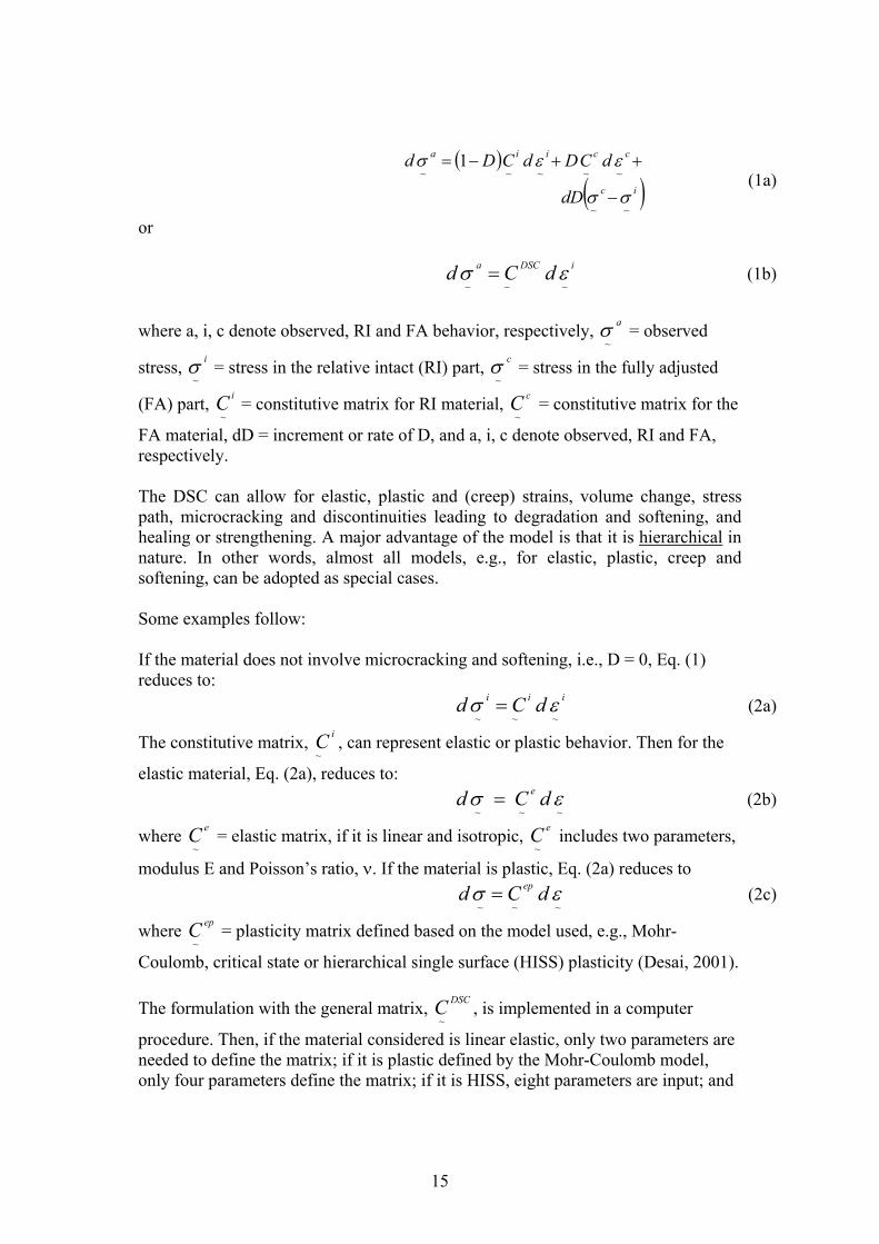
The DSC can allow for elastic, plastic and (creep) strains, volume change, stress path, microcracking and discontinuities leading to degradation and softening, and healing or strengthening. A major advantage of the model is that it is hierarchical in nature. In other words, almost all models, e.g., for elastic, plastic, creep and softening, can be adopted as special cases. Some examples follow: If the material does not involve microcracking and softening, i.e., D = 0, Eq. (1) reduces to: (2a) iii dCd
~~~εσ =
The constitutive matrix, , can represent elastic or plastic behavior. Then for the
elastic material, Eq. (2a), reduces to:
iC~
(2b) ~~~
εσ dCd e=
where = elastic matrix, if it is linear and isotropic, includes two parameters,
modulus E and Poisson’s ratio, ν. If the material is plastic, Eq. (2a) reduces to
eC~
eC~
(2c) ~~~εσ dCd ep=
where = plasticity matrix defined based on the model used, e.g., Mohr-
Coulomb, critical state or hierarchical single surface (HISS) plasticity (Desai, 2001).
epC~
The formulation with the general matrix, , is implemented in a computer
procedure. Then, if the material considered is linear elastic, only two parameters are needed to define the matrix; if it is plastic defined by the Mohr-Coulomb model, only four parameters define the matrix; if it is HISS, eight parameters are input; and
DSCC~
15

if it is softening with D ≠ 0, about eleven parameters need to be input. Figure 1 shows the hierarchical framework of the DSC. One of the advantages of the HISS/DSC models is that almost all parameters have physical meanings since they are associated with specific states during deformation. The parameters can be obtained from standard (triaxial) tests, and their number is equal to or smaller than those in other available models of similar capabilities. INTERFACES AND JOINTS One of the advantages of the DSC is that its mathematical framework for, “solid,” geologic materials can be specialized for interfaces and joints. This eliminates the usual practice of defining soils and interfaces by using different models (Desai 2001). LIQUEFACTION Since the DSC model is based on the changing microstructure during static or dynamic loading, the microstructural instabilities during deformation can be defined. One of such instability at the critical disturbance, Dc, can represent liquefaction (Desai 2000).
CRel
D ≠ 0
“Discontinuum”
ad~σ =
~
→= ei CC~~
= epi CC~~
= evpi CC~~
D = 0
ontinuum ative Intact
iii dCd εσ = ( ) ( )iccciia dDdCDdCDd 1 σσεεσ −++−=
~~~
Elastic
→Elastoplastic
→Creep
16
DSCC
iDSCa dCd εσ~~
=
~~~~~~~
D → Increasing
⇒ Microcracking, Discontinuities, Damage, Degradation,
Softening
D ← Decreasing
⇒ Strengthening, Healing, Stiffening

Figure 1. Hierarchical Adoption of Various Models from DSC. APPLICATIONS The DSC has been implemented in both static and dynamic nonlinear computer (finite element) procedures. A large number of practical problems such as foundations, dams, retaining structures, reinforced earth, tunnels, and boreholes, involving soil-structure interaction, have been solved using the DSC. Because of the generality of the DSC, it can also be used for a wide range of materials such as metals, solders, ceramics, and silicon, e.g., it has been applied successfully for cyclic thermomechanical behavior of computer chips in electronic packaging (Desai 2001). CONCLUSIONS The nonlinear behavior, mainly arising from the nonlinear material response of geologic materials, is complex compared to many other engineering materials. Hence, the researchers in the geotechnical area have developed models to account for increasing number of factors. One such model is the DSC, which, although developed for geomaterials, has been also used in the high tech area of electronic packaging to model the thermomechanical behavior of solders, ceramic, silicon, etc. However, since the geotechnical profession may not urgently demand higher and advanced models for their usual applications, the developed models have not found prompter use in practical design and analysis. The researchers could establish the ways to reduce the gap by more attention to practical use of their research, by writing papers that involve both fundamentals and application, by pursuing contacts such as through workshops and symposia in which both researchers and practitioners participate, and by educating the students in advanced topics that are important for problems for modern technological problems. The funding agencies should consider supporting studies involving use of developed models for practical applications. FUNDAMENTALS THROUGH APPLICATIONS In order for research results to be attractive in practice, the researchers should combine both fundamentals and applications in their research. This would entail a to-and-fro approach in which theory needs to be developed based on its application through validations of realistic problems, and practical applications can be evolved by refining the fundamental aspects of the theory used. In this process, both the researcher, with the knowledge of the theory, should continuously interact with the practitioner with the knowledge of the behavior of realistic applications. Research results developed through such integrated and symbiotic process could find prompter applications.
17
References Desai, C.S. (2000). “Evaluation of liquefaction using the Disturbed State Concept,” J. of Geotech. & Geoenviron. Eng., ASCE, 126 (7), 618-631. Desai, C.S. (2001). Mechanics of Materials and Interfaces: The Disturbed State Concept, CRC Press, Boca Raton, FL, USA. Desai, C.S. and Siriwardane, H.J. (1984). Constitutive Laws for Engineering Materials with Emphasis on Geologic Materials, Prentice Hall, Englewood Cliffs, NJ, USA. Duncan, J.M. and Chang, C.Y. (1970). “Nonlinear analysis of stress and strain in soils,” J. of Soil Mech. Found. Div., ASCE, 96 (5), 1629-1653. Kulhawy, F.H., Duncan, J.M. and Seed, H.B. (1969). “Finite element analysis of stresses and movements in embankments during construction,” Report 569-8, U.S. Army Corps of Engineers, Waterway Expt. Stn., Vicksburg, MI, USA.
18

Geotechnical Engineering Practice: Changing the Paradigm
K.L. Fishman
Abstract This paper describes the organizational structure of small to medium sized geotechnical engineering projects, and the paradigms associated with design and analysis of associated foundations and other geotechnical engineered systems. Changing these paradigms presents opportunities for more widespread application of advanced numerical techniques. Analyses of rock squeeze, seismic response, landfill foundation stability and settlements, and interpretation and back-analysis of NDT measurements present opportunities for more widespread implementation of advanced numerical techniques on small or medium sized projects. Specific steps to overcome the difficulties associated with implementation of advanced numerical techniques include identifying the appropriate target audience, understanding the strengths and weaknesses inherent to numerical analyses, understanding data requirements, and creating competition in the market place to encourage efficient and cost effective applications. . INTRODUCTION Advanced numerical methods are often applied to engineering analysis of large to mega-sized projects such as large dams, power plants, offshore works, long span bridges and underground works. However, the majority of geotechnical engineering practice involves design and construction of small to medium sized projects. Small to medium sized projects may include parking garages, commercial facilities, waterfront structures (quay walls), short to medium span bridges, expansion of industrial or municipal facilities, highway improvements, and waste containment facilities (landfills). The benefits resulting from application of advanced numerical methods are desirable for any project, regardless of size. However these benefits come at a cost that includes money, time and overall level of effort; including the need to prepare and acquire the necessary tools, training and resources. Opportunities to apply advanced numerical methods to geotechnical engineering practice should be distinguished in terms of the size of the project and the corresponding level of interaction between the various disciplines involved on the project. Obviously, small to medium sized projects do not enjoy the same resources as larger projects. The level of site investigation, in situ and laboratory testing is limited. Time is also a limited resource. Small to medium sized projects have a geotechnical engineering design phase that may only last a month, and the organizational structure of the design professionals engaged on the project is unique compared to
19

larger projects. Often the geotechnical engineer is a subconsultant, and does not have much input relative to the overall organization of a project, or to establish priorities. The geotechnical engineer’s scope of services are driven by cost, services are often bid, and the scope developed by architects or structural engineers. The geotechnical engineer’s charge is to characterize site conditions and make recommendations for design and construction of foundations, pavements, retaining walls, embankments and excavations. The most important issues surrounding these recommendations include characterizing the site in terms of the location of bedrock, groundwater and soil/rock types beneath the surface. Better information about these site features has the most impact on construction risk, and leads to more economical design of facilities. For larger projects, there may be ample resources remaining for detailed analysis subsequent to site characterization; but, smaller projects generally require decisions to be based on engineering judgment, supported with simplified methods of analysis. However, small to medium sized projects would benefit from advanced numerical methods leading to better understanding of the performance of constructed facilities during construction and throughout their service lives. Software must be well documented, and required input readily available from standard site exploration, sampling and laboratory testing. Those that plan and organize the project also need to understand the benefits of more detailed geotechnical engineering analyses. Promoters must do a better job of identifying the appropriate target audience, including professionals that are not necessarily geotechnical engineers, to encourage application of advanced numerical methods. This paper presents a discussion, with specific emphasis on small to medium sized projects, of the appropriate target audience, routine problems that that would benefit from application of advanced numerical methods (i.e., simple methods are grossly inadequate or do not exist), and input/data requirements. Specific steps to promote implementation of advanced numerical methods are described followed by a few conclusions based on the author’s experience and thoughts relevant to the workshop topic. TARGET AUDIENCE What is the “geotechnical engineering community?” Some people have a relatively narrow view of geotechnical engineering; limited to a set of activities described as “drill, test, report,” which involves only subsurface exploration, site characterization, and recommendations for design of foundations, etc. Many agencies consider detailed design of the foundation elements, and earth structures, including retaining walls and earth support structures, to be within the domain of structural engineers or architects. For many projects, a client, through the architect or structural engineer, will prepare a bid package for geotechnical engineering services through which the services are strictly specified, i.e., the services are a commodity and are awarded to the lowest bidder. Thus, the advantages of
20
performing a more sophisticated analysis that may consider the effects from soil-structure interaction (for instance) are not incorporated into the planning and design process. Generally, there is a well-defined division of responsibilities between the general civil, structural and geotechnical engineer and very little face-to-face interaction between these specialists. Geotechnical engineers need to broaden their impact on projects and be part of the design process from the earliest stages of a project. Also, we need to identify ourselves as “structural engineers” as necessary to be consistent with the perceptions of potential clients. Lastly, structural engineers and architects should also be educated about the merits of advanced numerical analyses. We should endeavor to convince our counterparts that there is a greater need for geotechnical input, or at least train individuals in related disciplines to be better “geotechnical engineers”. APPLICATIONS Advanced numerical methods are useful to compute stresses and deformations; and incorporate the important effects of soil-structure interaction, stress path, staged construction, load level, pore water, material nonlinearity, nonhomogeniety, time and complex geometry in the analysis. Application of advanced numerical techniques is facilitated if results may be obtained relatively quickly, software and data necessary for the analysis are readily available and in a convenient format. Data preparation including generation of mesh geometries is facilitated if the preprocessing software is linked to AutoCAD software, which is available in most engineering design offices. Several examples, where advanced numerical techniques may be more readily applied, are discussed in the following paragraphs. Excavations within rock formations are often subject to time-dependant deformations resulting in rock squeeze or closure of the excavation. Buckling or heave along the base of the excavation sometimes accompanies rock squeeze. Simplified methods of analysis are not available for these problems, and empirical relationships are unreliable unless the geometry of the excavation is similar to those used to develop the relationships. The excavation may often be modeled as plane strain, or axisymmetric, and software packages, which are not very demanding in terms of computational effort, are readily available. Many states recently adopted the International Building Code (IBC) as the construction industry standard for building construction and site development. Thus, many jurisdictions (including those in the central and eastern US) now require engineers to assess the seismic risk, assign seismic parameters for design, and perform seismic analyses that may include pushover. Simplified methods are often used to access seismic vulnerability including site response, liquefaction assessment, seismic induced permanent deformation, and mechanisms of shear transfer. However, if the site conditions or preliminary designs are deemed to be vulnerable based on results from more conservative, simplified methods of analysis, then the
21

engineer should undertake more advanced analyses. Advanced numerical techniques should be used to assess site conditions, ground response and behavior of the structure considering the effects of soil-structure interaction, nonlinear stress-strain soil behavior and inherent damping. Advanced numerical techniques may be useful to understand the seismic response of different types of earth structures, and seismic resistance offered by sophisticated foundation systems. Potential savings with respect to more accurate description of the need for ground improvement, or providing seismic resistance, justify the cost and effort associated with advanced analysis. Engineering analysis of landfills and waste containment facilities includes foundation stability and settlement. The subgrade beneath the landfill liner is often a thick clay layer. For landfill expansions, the new liner may be piggy-backed on top of an existing cap, and the stability and settlement of the existing waste pile is analyzed. The properties of the subgrade and waste are time dependant, and consideration of the three dimensional geometry is important with respect to rate of consolidation, corresponding strength gain of the foundation over time, and accumulation of differential settlement. The engineering analysis section is part of the landfill permit application submitted to the regulatory agency. Improved predictions achieved with advanced numerical methods allow for increased capacity of the landfill. The cost of the analysis is justified to landfill operators because air space is a valuable commodity. The engineer-of-record, is often a geotechnical engineer, who works with the owner to develop the scope of engineering services. Therefore, application of advanced numerical methods has potential if the engineer is convinced of the benefits, and has the resources and support necessary for implementation. Nondestructive testing (NDT) is applied for quality control of constructed facilities including deep foundations, and for element condition assessment or identification of existing systems including foundations, retaining walls or earth reinforcements. These NDTs monitor the response of the system to a given excitation. The condition of various elements in terms of stiffness, continuity and geometry is inferred from the results of analyses wherein these attributes are input into an inversion algorithm. The algorithm performs iterations of computed responses to a given excitation. The system is perturbed until there is agreement between the computed and observed response within a specified tolerance. Numerical methods are useful to consider the effect of soil-structure interaction, material damping, complex geometry, and the presence of discontinuities. The problem involves dynamic loading, but the levels of strain are very low such that the material behavior may be considered as elastic. Software for performing these inversions is often proprietary and marketed as an integral part of the NDT test kit. INPUT PARAMETERS FOR ADVANCED NUMERICAL METHODS Uncertainty of input parameters exists due to spatial variation of soil properties, errors inherent to sampling, testing and data interpretation, or uncertain loading
22

conditions. Application of sophisticated mathematics to solve the problem is not justified unless the input can be determined accurately, and deemed reliable. Input data should be gathered from a large enough data set such that material properties are representative of overall site conditions. Equipment and techniques required for sampling and testing should be readily available and, to the extent possible, test results should reflect the appropriate stress paths. Even well established laboratory test techniques including conventional triaxial, or simple shear testing are not routinely included in the scope for many small to medium sized projects. Correlations between input parameters and index tests are desirable for rapid assessment of input properties, and allow for a large enough data set to assess the reliability of selected input parameters. The most significant data requirements should be identified, and, whenever possible, default parameters provided by the software. Databases of typical material properties and input parameters for various models are a valuable resource, and promote more widespread application of advanced numerical techniques. Useful databases can be developed if the soil/rock constituents can be estimated, or are well established. Properties and parameters inherent to particular rock formations may prevail over large areas, and a regional database of appropriate input parameters including elastic constants, ultimate strengths, creep model parameters and in situ stress regimes may be developed. Properties for select materials, placed and compacted during construction are relatively uniform and consistent compared to in situ soils. Earth structures, such as mechanically stabilized earth, utilize engineered backfill for which a database of input parameters useful for numerical analysis could be developed. Results from studies to characterize municipal solid waste are available and further research is needed to correlate these characteristics with appropriate parameters needed for advanced numerical techniques. Simple correlations between different soil types and relevant material properties should be developed similar to the relationships between strength and stiffness available for coarse or fine-grained soils. These goals are more challenging for sophisticated constitutive models that incorporate many material parameters. However, if the model parameters are kept to a minimum, and each is associated with some physical interpretation, correlations with index properties such as void ratio, water content, Atterberg limits, fines content, etc. are possible. Specific Steps to Promote the Use of Advanced Numerical Methods:
1. Identify the appropriate target audience to promote application of advanced numerical methods. Revise our definition of geotechnical practice and consider the organization for a typical small to medium sized project.
2. Clearly demonstrate the benefits from application of advanced numerical techniques. Case studies are necessary to exhibit improvements in design and cost savings compared to traditional approaches.
23

3. Recognize the needs for additional field investigation and understand current limitation of the practice, i.e., equipment, and expertise must be readily available for in-situ testing, sampling or laboratory testing.
4. Competition in the market place is needed before applications are fairly priced. Currently, obtaining specialized software or performing specialized sampling and testing is expensive because only a few firms or universities are able to perform the required services, or provide the necessary equipment or software.
5. Don’t oversell application of advanced numerical methods and clearly describe the limitations. Numerical modeling alone will not provide the optimal design solution. Engineers need to consider variables in design and understand the uncertainty associated with numerical results. Many constitutive modelers have a very “determined” approach to describing the behavior of geomaterials. The sense is that it’s a matter of including all of the physical processes contributing to the response to achieve an accurate model. However, often the presence of a soil layer at a site, and its extent, are uncertain. Properties may very spatially and temporally, and these need to be quantified. Numerical models must consider the effect of construction and stress history on soil properties, e.g., driven pile foundations are often “wished in place” and the effect of pile driving on the soil properties is not considered. The use of advanced numerical methods must achieve parity with other methods in use that are incorporated into reliability-based designs. If increased certainty in design can be demonstrated, then the advantages of advanced numerical methods will become more apparent.
6. One failure negates the progress made from 1000 successes in terms of educating the engineering community about the benefits of using advanced numerical methods to solve geotechnical engineering problems. The engineering community tends to have a selective memory that reduces the collective knowledge into the simplest terms, such as “these methods don’t work.” Endeavor to report cases where applications of advanced numerical methods have failed and clearly describe how models, analyses, sampling practices, selection of parameters, etc., may have been misapplied and contributed to the problem.
CONCLUSIONS The attributes of small to medium sized projects and the existing paradigms with respect to project execution are discussed. Several issues are identified where the benefits from application of advanced numerical methods may be realized on small to medium sized projects. These include region-wide problems that may be related to geologic origin of soil or rock types, detailed analysis of seismic response including site-specific analyses as necessary, and engineering analyses required for permit applications. Model parameters should be estimated from simple correlations with index properties and from databases associated with material constituents. In practice, it is useful to effectively vary parameters for a given model, and anticipate a range of response.
24

Specific steps to promote the use of numerical methods include identifying the appropriate target audience that may also include structural engineers, architects and owners; and describing the advantages and limitations associated with applications of advanced numerical methods. Case studies are needed to publicize the successes, as well as the failures, associated with application of advanced numerical techniques.
25
A Comprehensive Approach to Modeling the Behavior of
Unsaturated Soils Using an Elastoplastic Framework
K.K. (Muralee) Muraleetharan
School of Civil Engineering and Environmental Science, The University of Oklahoma,USA
Chunyang Liu
School of Civil Engineering and Environmental Science, The University of
Oklahoma, USA
Abstract Unsaturated soils are involved in many catastrophic failures. Recent mudslides in Guatemala and the landslide in La Conchita, California are some examples of catastrophic failures involving unsaturated soils. Even the levies that failed in New Orleans during the Hurricane Katrina contained both saturated and unsaturated soils. The complex nature of the unsaturated soil behavior involving soil skeleton, pore liquid, pore gas, and the interfaces between these bulk phases has led the engineers to resort to empirical procedures for designs. Engineers often assume these soils are either fully saturated or completely dry. These assumptions lead to either too conservative or unconservative design practices and incomplete understanding of the behavior of structures. Realistic static and dynamic analysis of multiphase porous media, such an unsaturated soil, however, requires a procedure that can rigorously describe all the interactions between various phases and interfaces. Such a procedure is generally called a fully coupled analysis procedure. A key component of a fully coupled analysis procedure is the description of the stress-strain behavior of the soil skeleton. Stress-strain behavior of unsaturated soils is elastoplastic, similar to that of saturated soils, but more complicated by the effect of suction (pore gas pressure minus pore liquid pressure). Starting in 1990 researchers began to address the stress-strain behavior of unsaturated soils within the framework of critical state soil mechanics and thereby incorporating elastoplasticity into consideration. Although the effect of suction was taken into account by these constitutive models, the variation of suction with water content (i.e., the soil-water characteristic curve) was still treated as an external quantity. This is contradictory to available experimental and theoretical evidence that suggest suction is not only a function of water content, but also depends on the deformation of the soil skeleton. Furthermore, the observed hysteresis in the soil-water characteristic curve (SWCC) points to an energy dissipation mechanism that should be considered in the constitutive modeling of soils.
26

This paper presents a comprehensive approach to modeling the stress-strain behavior and SWCC of unsaturated soils within an elastoplastic framework. A bounding surface plasticity theory is used to predict the relationship between suction and water content, including the hysteresis, for unsaturated soils. Once the model parameters have been calibrated along a drying curve the model is able to predict the wetting curve and other scanning curves successfully. The model predictions are validated using SWCC rapidly measured for a sandy soil using an innovative, computer controlled, parallel, miniature pressure plate device. Guidelines are provided on how to couple the stress-strain and the SWCC for unsaturated soil to develop a fully coupled constitutive model.
27

Thermo-Hydro-Mechanical Effects In Fluid-Saturated
Poroelastic Geomaterials
A.P.S. Selvadurai
Department of Civil Engineering and Applied Mechanics, McGill University, Montréal Canada
Abstract Thermal loading of geomaterials is encountered in a variety of areas in geomechanics including geologic disposal of heat-emitting nuclear fuel wastes, thermal stimulation of resource bearing formations, behaviour of buried electricity transmission cables and ground freezing during construction and in the transmission of energy resources, such as chilled natural gas. This note presents a brief outline of the classical techniques for characterizing isothermal and non-isothermal poroelasticity and indicates recent approaches to incorporating the influences of damage development on the mechanics of the fluid-saturated medium. Furthermore, the thermo-poroelasticity problem can be rendered non-linear if the parameters governing the mechanical deformations and the fluid transport processes in particular are influenced by the temperature. INTRODUCTION The classical theory of poroelasticity formulated by M.A. Biot (J. Appl. Phys., 1941) is a significant development in modern continuum mechanics that has found applications in a variety of areas in engineering and materials science ranging from geomechanics to biomechanics. The key assumptions in Biot’s theory of poroelasticity relate to the Hookean behaviour of the porous skeleton and Darcy flow of the fluid through the porous space. This gives rise to a set of linear partial differential equations governing the hydro-mechanical coupling between the deformations of the porous skeleton and the pressure in the pore fluid. The existence of solutions to this system of coupled partial differential equations and their uniqueness is now well established. The assumption of incompressibility of the pore fluid is almost invariably present in the application of the classical theory of poroelasticity to geomaterials, such as dense clays and soft rocks where the compressibility of the pore fluid is substantially smaller than that of the porous solid. In these cases the porous skeleton itself might exhibit a variety of complex constitutive phenomena that could include irreversible and rate-dependent phenomena such as elasto-plasticity and viscoplasticity applicable to geomaterials undergoing large strain phenomena. Such irreversible phenomena can also be accompanied by alterations in the fluid transport characteristics of the pore skeleton. When considering more competent geological media, the influence of the compressibility of the pore fluid becomes important, and the constitutive formulations of classical poroelasticity are generally capable of examining such
28

influences. There is a third type of situation where the pore fluid can exhibit compressibility effects due to the presence of compressible constituents distributed within it in a uniform manner. Specific examples of such a situation are when a pore fluid such as water contains small amounts of dissolved air or the pore water that contains small concentrations of a hydrophilic fluid that is both uniformly distributed and unattached to the porous solid. In these circumstances, the pore fluid can be treated effectively as a gassy fluid occupying the entire pore space but with compressibility consistent with that of an unsaturated fluid mixture. Admittedly, this type of assumption is a reliable approximation only in a limited set of circumstances where the phases do not exist as separate regions within the pore space, at least in a continuum sense. A further recent extension to classical poroelasticity deals with the evolution of damage in fluid-saturated media. In a phenomenological sense, damage is interpreted as the evolution of micro-cracks and micro-voids that can alter the elasticity and fluid transport characteristics of the poroelastic medium. The approaches to interpreting evolution of micro-mechanical damage utilize either crack nucleation and crack extension concepts or recourse is made to the determination of damage evolution by appeal to experiments. THERMO-POROELASTICITY Classical thermo-poroelasticity is generally an extension of the classical theory of poroelasticity to include the influences of temperature. Such extensions can be accomplished at various levels, the simplest being the introduction of a point space distribution of temperature as a dependent variable. An additional constitutive relationship should then be introduced to describe the heat transfer process in the porous medium. Ideally the introduction of temperature as a variable requires the consideration of the influences of deformations of the porous skeleton and the movement of the pore water on the heat generation process. In the case of competent geomaterials such as intact rocks that are subjected to heat flow, these influences are considered to be of secondary importance and the mode of heat transfer is largely restricted to the heat conduction in a porous medium with a sessile fluid. Both the mechanical deformations of the porous skeleton and fluid transport processes are assumed to be influenced by temperature. When considering thermo-hydro-mechanical effects, attention is also restricted to transient heat conduction processes in the fluid-saturated medium and any unsaturation effects are modelled through the introduction of an effective compressibility consistent with a dissolved air fraction. In addition to the consideration of heat conduction, Darcy flow and elastic deformations of the system, it is necessary to introduce an effective stress equation that relates the total stress tensor to the effective stress tensor and the pore fluid pressures. The original form of Darcy’s law and Biot’s equation for the effective stresses are assumed to remain unaltered in the presence of thermal effects. For example, if we consider the non-isothermal mechanics of a porous medium that is saturated with a compressible pore fluid, the partial differential equations governing the displacement field , the temperature and the pore fluid pressure
can be obtained by combining the Duhamel-Neumann extensions to Hookean elasticity, Darcy’s law applicable to the flow of the fluid through the pore space,
),( txu ),( tT x),( tp x
29

Fourier’s law for pure heat conduction through the saturated medium and the appropriate conservation laws applicable to mass, momentum and energy. These equations can be written in the forms
tTCT∂∂
=∇ ρκ 2
(1) 0Fuu =+∇+∇+∇∇++∇ TKpGG Dβαλ ).()(2
(2)
[ ] 0)1()1().(2 =∂∂
−−−−+∇∂∂
+∂∂
⎟⎟⎠
⎞⎜⎜⎝
⎛+−−∇
tTnn
ttp
KKn
Knpk
fssff
βββαααµ
u
(3) where and G λ are the linear elastic Lamé constants; κ is the thermal conductivity of the bulk poroelastic medium; Cρ is the heat capacity of the bulk porous medium; is the permeability of the porous medium; n is the porosity of the medium;
ksββ , and fβ are respectively, the drained thermal conductivity of the
porous fabric, the thermal conductivity of the solid phase and the thermal conductivity of the pore fluid; and are, respectively, the bulk moduli of the drained material, the solid phase and the fluid (we note that if the fluid contains an air voids content, then this term should be interpreted as the effective bulk modulus of the fluid) ;
sD KK , fK
µ is the kinematic viscosity; )]/(1[ sD KK−=α ; F is a body force vector and ∇ is the gradient operator. In order to complete the formulation of a specific boundary value problem it is necessary to prescribe appropriate boundary conditions for the dependent variables and . These can be the usual Dirichlet and Neumann boundary conditions applicable to these variables. In addition, appropriate initial conditions should also be prescribed. Considering the thermodynamic requirements for a positive definite strain energy potential it can be shown that the material parameters should satisfy the following constraints:
T,u p
0;0;5.01;1~0;0 >>≤<<−≤≤> κνν kBG u , where B~ is the pore pressure parameter defined by Skempton and both α and β are related to the undrained Poisson’s ratio uν and B~ as follows:
( )( )( )u
u
B νννν
α+−
−=
121~3 ( )( )
( )( )uu
uGννννν
β219
1212 2
−−+−
=
(4)
NON-LINEAR ASPECTS
The conventional approach to computational modelling of the thermo-poroelasticity problem is to extend the methodologies developed for computational modelling of the isothermal problem for fluid saturated media and to include temperature as a dependent variable. These developments are summarized in a number of key articles
30

and texts that have appeared over the past half a century and the interest in this area is almost unquenchable. In the linearized problem, the appropriate matrix equations applicable to the partial differential equations (1) to (3) can be written as follows:
[ ][ ] [ ]{ }
{ } { } [ ] [ ][ ]{ }0
1
)/()1(
)/(
TCMKHFQFH
TCMKH
tC
tC
∆+−++
=∆+
ρθ
ρθ
(5)
[ ] [ ][ ] [ ] [ ]
{ }{ }
{ }
[ ] [ ][ ] [ ] [ ]
{ }{ }
[ ] [ ][ ] [ ]
{ } { }{ } { } ⎭
⎬⎫
⎩⎨⎧
−+−
⎥⎥
⎦
⎤
⎢⎢
⎣
⎡+
⎭⎬⎫
⎩⎨⎧⎥⎥
⎦
⎤
⎢⎢
⎣
⎡
−−
−−+
=⎭⎬⎫
⎩⎨⎧⎥⎦
⎤⎢⎣
⎡−∆−
01
10
0
0
1
1
)1(
)1(
)1()1(
TTTT
CM0
0K
pd
CMKPCP
CPK
fpd
CMKPCPCPK
θθ
βθ
β
θαθ
θαθ
θ
θαα
e
D
eT
e
K
c
ct
(6)
where the unknowns are the displacements { }1d , the nodal temperatures { and the
nodal pore pressures { } at the current time step, and
}1T1p { }0d , { }0T and { } are
respectively the nodal displacements, the nodal temperatures and the nodal pore pressures at the previous time step,
0p
{ }f is a vector of generalized “forces”, and{ are heat flux vectors, {FQ} }FH θ is a time integration constant and , ,
etc., are assembled from element matrices, which are dependent on thermal, mechanical and hydrological properties of the individual elements and the interpolation functions used. In the case of a porous medium with a compressible pore fluid, ;
[ ]K [ ]CP
111 )()()( −−− +−= ssfe KKnKnc α fse nn βββαβ −−−−= )1()1( .As has been noted in the literature, the time integration constant θ varies between zero and unity. Stability of the solution can, however, be realized within the first three to four steps by setting 75.0=θ . The accuracy of the finite element technique has been verified through comparison with classical analytical solutions for both isothermal and non-isothermal initial boundary value problems. Influences of nonlinearities will come into effect if the poroelastic medium experiences hydro-thermo-mechanical damage similar to that described previously in connection with the isothermal case. In this case the resulting problem has to be formulated in an incremental fashion with the solution procedure following a conventional Newton-Raphson-type iterative scheme. Other forms of non-linearities can materialize in poroelastic media with sparse discontinuities such as fractures and fissures, the properties of which can evolve with the coupled processes. CONCLUDING REMARKS
31
The classical isothermal theory of poroelasticity can be extended in a general way to include the influences of thermal effects. The couplings associated with such extensions can be simplified when the mode of heat transfer is restricted to heat conduction in the multiphase medium. Other extensions, to include damage mechanics and poro-elasto-plasticity of discrete discontinuities, can also be achieved in a straightforward way. These developments show promise both in terms of experimentation and computational developments and in their applicability to competent geomaterials ranging from granite to argillite. The extension of poroelasticity to include finite strain elastoplasticity has been somewhat sketchy, largely due to the absence of experimental information for the accurate characterization of constitutive responses. Similar comments can be made with regard to the development of computational approaches for the study of geomaterials that experience large strain effects, unsaturation and phase separation in the presence of thermal effects.
32

On the Microstructural Aspects of Granular Material
Behaviour
Richard Wan
University of Calgary, Alberta Canada Abstract The constitutive modelling community has begun to latch upon the idea of geomaterial behaviour being dominated by its microstructure which determines the observed mode of failure. Conversely, this means that it is not sufficient to solely analyze the failure of geomaterials in the conventional manner such as through a failure criterion, but it is equally important to study the causes leading to failure. The path to failure is mainly micromechanical in character as it pertains to local instabilities such as inter-granular slippage and overriding, buckling of internal force chains, and grain crushing, among others. Micromechanically driven phenomena such as dilatancy and grain crushing are precursors to well-known deformational features like shear bands and compaction bands respectively. A micromechanically based constitutive model together with its predictive capabilities will be presented. The mathematical formulation penetrates right down to details of grain activity at the meso-scale, and back to the macro-scale through a purely micro-mechanical analysis. The result is a non-phenomenological constitutive model with a fabric embedded stress dilatancy equation that has much higher resolution than that offered by conventional plasticity theory. The basic premise is that a granular material has at the outset a certain potential to dilate. The degree of ‘unlocking’ of the inherent dilatancy is merely a function of the loading (stress or strain imposed) and its fabric. We thus examine various fabric dominated geomaterial behaviours that the model can capture in both monotonic and cyclic loading regimes. In the monotonic loading regime, special reference is made to the deformation of geomaterials along strain paths with an imposed volumetric strain rate that can be dilative, compactive or isochoric. It is demonstrated that depending on the magnitude of the applied volumetric strain rate, the material behaviour can change from one which is stable with strain hardening at moderate dilation rates, to one which is unstable (flow deformation type) at extreme dilation rates. In practical terms, it transpires that a sand, otherwise stable under isochoric (undrained) conditions, can actually succumb to an instability or a flow type of behaviour under other loading paths, such as for instance, a slightly dilatant path. This further suggests that flow type of failures in soils may not be necessarily restricted to the classic saturated loose sand case in undrained conditions, but could manifest itself under other conditions as well, even in the absence of any fluid.
33

In the cyclic regime, we examine soil ratcheting behaviour, whereby plastic strains and densification/dilation accumulate cycle by cycle. An example in which soil ratcheting occurs is in the soil-structure interaction between an integral bridge and a granular backfill. The latter is subjected to cyclical strains during the thermal expansion and contraction of the bridge deck. While these strains are small, they slowly change the fabric and dilatancy characteristics of the backfill so that plastic deformations accumulate cycle by cycle leading to time dependent deformations. This phenomenon cannot be captured by simple constitutive models such as the perfectly plastic Drucker-Prager model. The predictive capabilities of a micromechanically based constitutive model will be discussed. In closing, the use of advanced numerical methods in geotechnical engineering can only be promoted through a modernization of the curriculum at the undergraduate level. A holistic approach must be taken towards the teaching of soil mechanics. A robust framework such as Critical State soil mechanics should be adopted whereby concepts such as critical friction angle, dilatancy and grain crushing are working tools the engineers should be conversant with. Also, any constitutive model developed should only have a few parameters that are fundamental and physically meaningful. The latter parameters should be cast within existing frameworks that the geotechnical engineer is familiar with.
34

Continuum framework for three-phase soil including
microstructural effects
X.S. Li
Hong Kong University of Science & Technology, Hong Kong Abstract Modern treatment of geotechnical problems is rooted in the continuum theory of immiscible mixtures. Since the first general continuum theory of mixtures was proposed by Trusdell & Toupin in 1960, significant progresses have been made towards the establishment of a rigorous framework for this branch of continuum mechanics. A fundamental concept in all the developed theories is that the constituents in a mixture are treated as superimposed continua. That is, each point in a mixture is simultaneously occupied by a material point of each constituent. This abstraction of actual placement of constituents is essential for the development of all mathematically tractable continuum theory of mixtures. In the pioneering theory of Trusdell & Toupin, the local balance equations for each constituent is written in their usual forms for a single continuum and the actions of other constituents are taken into account by adding growth (internal supply) terms. However, this type of theories does not take the volume fractions of the constituents into account, therefore does not suitable for geotechnical applications, in which the volume fractions of the solid and fluid phases profoundly affect the soil behaviour. To take the volume fractions into account, a solution procedure must be developed in the context of immiscible mixture theories, in which a multiphase material is defined as those whose constituents remain physically separate on a scale much larger than molecular dimensions but much less than macroscopic inhomogeneities, In the theory, the volume fractions are treated as independent kinematic variables. Because there are no macroscopic balance equations related to the volume fractions, the evolution of the volume fractions must be defined at a microstructural level. A popular approach in this regard was proposed by Goodman & Cowin (1972), who suggested that the evolution of the volume fractions be governed by additional balance laws, referred to as the balance of equilibrated force. This approach to describing changes in the volume fractions results in a rich theoretical structure requiring additional constitutive equations. Applying the immiscible mixture theory to three-phase soil yields a microstructural stress in each phase that is related to the gradient of the porosity or of the degree of saturation. This framework paves a way of describing transient of the soil behaviour from a solid to a fluid (post liquefaction, debris flow, etc.) state. It is also interesting to note that the gradient of porosity and the gradient of degree of saturation are interrelated, indicating that wetting is naturally associated with a volume change. In the context of computational soil mechanics, it is suggested to define constitutive
35

relations between a seven-component strain and a seven-component stress, with the invariant of the gradient of the porosity as the additional strain component and the partial derivative of the Helmholtz free energy with respect to this additional strain component as the additional stress component. This presentation will highlight some of these interesting findings.
36

A Key Issue In Small Strain Modeling:
Capturing The Dependence Of Soil Response On The Direction Of Loading
Cino Viggiani
Laboratoire 3S, Grenoble, France
Abstract Non–linearity is a striking feature of the mechanical behavior of natural soils. Its impact on the observed behavior of geotechnical structures has been the subject of a large number of intensive studies over the last decades. Major contributions include the development of techniques for local deformation measurement on laboratory specimens, back analyses of field measurements in carefully instrumented case histories, and various types of numerical studies. In particular, soil non–linearity may strongly affect the nature and amount of ground movements around excavations. Already back in 1979, Simpson et al. showed, for example, that the use of a non–linear elastic–perfectly plastic model with high stiffness at very low strain levels could significantly improve the quality of FE predictions of excavation–induced ground movements in London clay. It should be noted that the quality of ground movements prediction has important practical implications in the design of retaining structures in urban areas, in connection with possible effects on nearby structures and existing underground services. From the standpoint of constitutive modeling, various approaches have been suggested for dealing with soil non–linearity. Classical elastoplasticity with strain–dependent elastic moduli (variable–moduli models) has been often adopted. Variable–moduli models have indeed largely inspired much of the experimental research carried out on pre–failure deformation of geomaterials over the last decade. In the early 90s, Stallebrass & Atkinson proposed the concept of kinematic hardening with multiple nested surfaces as a convenient way to deal with both non-linearity and the effects of recent stress history. It is worth noting that, in principle, non-linearity and history dependence can also be described by many different inelastic theories, including generalizations of classical plasticity (bounding surface plasticity, see Dafalias 1986; generalized plasticity, see Pastor et al. 1990) and models developed from basic principles of continuum mechanics (hypoplasticity, see Kolymbas 1991). All the approaches mentioned above are capable of describing soil non–linearity as observed in the laboratory from the stress–strain response in loading paths of finite size. However, an important difference exists between variable–moduli models and
37

all the others. In the variable–moduli models, for states far from the yield surface, stress and strain rates are related through a unique tangent stiffness tensor, which is possibly dependent on the current state but is independent of the loading direction. On the contrary, all the other approaches are characterized by an explicit dependence (either discrete or continuous) of the current tangent stiffness tensor on the direction of applied load. This load direction dependence introduces a new concept of non–linearity, which can be referred to as incremental non–linearity (after Darve 1978, 1991). Incremental non–linearity is independent from the common notion of non–linearity and provides the necessary means to correctly describe irreversible deformation upon loading–unloading cycles. The directional character of soil behavior, i.e., the effect of loading direction on the observed response of the material, is in essence what this paper is about. We will first discuss a few selected results from a recently performed experimental testing program on a fine–grained soil. Then, we will illustrate through a numerical example the practical impact of incremental non–linearity on the FE predictions of ground response. The case of an excavation has been selected as a benchmark for evaluating the influence of constitutive assumptions on predicted behavior, since in this case the soil undergoes strongly non–proportional stress paths and large differences generally exist between stress path directions in different regions of the surrounding soil.
38

Some Important Aspects of the Mechanical Behaviour of Soils
under Cyclic Loading
Thomas Meier Institute of Soil Mechnics and Rock Mechanics, University of Karlsruhe, Germany
Abstract Today many constitutive equations are available for the description of the mechanical behaviour of soils. However, only a few of them are able to model the fundamental aspects of the soil behaviour, realistically, viz the critical state and the influence of the effective pressure (barotropy), density (pyknotropy), the most recent deformation history, the path-dependency and viscosity on the shear resistance and stiffness. Comprehensive constitutive models, which incorporate all of the above mentioned aspects, are e.g. the so-called hypoplasticy and visco-hypoplasticity models, both developed in Karlsruhe over the last twenty years. An advantage of the (visco-) hypoplastic theory is the strict distinction between material constants and the state variables, i.e. effective pressure and density. With only one set of parameters, which can be obtained from standard laboratory tests, it is possible to simulate the behaviour of a given soil over a wide range of pressures and densities. In combination with numerical methods like the Finite Element Method these constitutive models allow the analysis of a wide variety of geotechnical boundary value problems, e.g. in connexion with (deep) foundations, (deep) excavations, tunnelling, open pit mining or soil-structure-interaction during earthquakes. With respect to the modelling of cyclic soil behaviour, the number of experimentally validated constitutive models reduces drastically. Almost without exception, these models can only be applied to problems like earthquakes, which include dynamic or cyclic loading with only a limited number of loading cycles. At present there are practically no models, which are able to predict the accumulation of deformation due to thousands or more loading cycles. Such models are urgently required in practice, especially for the assessment of stability and serviceability of off-shore constructions, such as windmills, oil rigs or large bridges, which are permanently subjected to wind and waves. But also settlements of railways or machine foundations cannot be realistically predicted, so far. In this contribution the mechanical response of soils under monotonic and cyclic loading is analysed and compared with the behaviour, calculated with the aid of the (visco-) hypoplastic constitutive equations. Numerical solutions to geotechnical boundary value problems are compared with experimental results in order to validate the proposed constitutive laws under real conditions. The necessity for further
39

development in the field of constitutive modelling for the analysis of structures subjected to a large number of loading cycles is shown.
40

Significance of Modeling Dilatancy in Geomechanics
Majid T. Manzari
Department of Civil and Environmental Engineering, George Washington
University Washington DC, USA
Abstract Shear induced volume change of granular materials has long been recognized as a key contributing factor to soil shear strength and geotechnical engineers have stressed the importance of accounting for this phenomenon in geotechnical design over the past decades. Nevertheless, in many geotechnical engineering computations there is a tendency to use simplified constitutive models that may not be able to adequately represent soil dilatancy. This has lead to failure in providing reasonable estimation of deformations in various geotechnical systems. In this presentation, two examples of such failures are presented to demonstrate the shortcoming of such simplified models in the modeling permanent deformations in earthquake induced liquefaction and in the estimation of ground settlement near a braced excavation. It is shown that in both cases, the lack of a suitable mechanism for modeling shear induced volume change has led to obtaining an entirely inaccurate pattern of deformation.
41

Soft Computing Approaches to Constitutive Modeling in
Geotechnical Engineering
J. Ghaboussi
Department of Civil and Environmental Engineering, University of Illinois at Urbana-Champaign, Urbana IL, USA
Y. M. Hashash
Department of Civil and Environmental Engineering, University of Illinois at
Urbana-Champaign, Urbana IL, USA
Abstract Biologically inspired soft computing methods are based on the problem solving strategies that occur in nature, and they are very effective in solving difficult inverse problems in engineering, such as constitutive modeling. Neural networks are biologically inspired soft computing tools. The authors have successfully used neural networks in constitutive modeling in geotechnical problems. The primary advantage of neural networks in constitutive modeling is their ability to extract information from the data that contains that information. Measurements data from many routine geotechnical monitoring systems during and after the construction contain information on the constitutive behavior of soils. SelfSim (Self-learning Simulations) is a methodology developed by the authors for extracting the information on the constitutive behavior of soils from measurement data generated during the construction. As more data becomes available, the accuracy of the neural networks constitutive models increase. SelfSim provides a framework for integrating the computational simulation during the construction. The data generated during the early stages of construction can be used to train neural network constitutive models that can be used to predict the later stages of the constructions. Authors have successfully used the SelfSim framework in structural, geotechnical and bio engineering problems. After describing the basic methodology, the application of SelfSim in deep excavations in urban areas will be discussed. In computational simulation of deep excavations during the design phase a trained neural network constitutive model from similar soil conditions can be used. During the early stages of the excavation, as more and more measurement data becomes available, the neural network constitutive model is updated in SelfSim, and the accuracy of the predictions of the wall displacements and surface settlements for the latter stages of the construction increases. SelfSim allows seamless integration of computational simulation with neural network constitutive models during the design and construction phases of geotechnical engineering projects.
42
Nonlinear Modelling Of Soils
David Muir Wood
University of Bristol, United Kingdom
Abstract INTRODUCTION The development of constitutive models that will actually be used by geotechnical engineers requires a combination of successful simulation and calibration, with physical reasonableness and with a ring of familiarity. The eventual choice of geotechnical constitutive model is a matter of mathematical aesthetics and subjective judgement. The models described here have been developed hierarchically from concepts of strength and stiffness with which most practising engineers are familiar: some models have been so widely used that they are generally available in all geotechnical numerical analysis programs: isotropic elasticity; elastic-perfectly plastic Mohr-Coulomb; and Cam clay. Two lines of development have therefore been followed: Mohr-Coulomb and Cam clay.
EXTENDED MODELS FOR SAND Mohr-Coulomb failure is familiar to all undergraduate civil engineers; the elastic-perfectly plastic Mohr-Coulomb model is available in most finite element programs used by practising civil engineers. Even though it is widely used, the concept and operation of Mohr-Coulomb as a complete constitutive model are unfamiliar to many engineers. Nevertheless, a hierarchy of models can be constructed by progressively adding extra features to this basic Mohr-Coulomb model: non-associated flow, distortional hardening, strain softening, kinematic hardening. Severn-Trent sand (Gajo & Muir Wood, 1999a, b) is a distortional hardening model with a subtle but elegant link between strength and density and dilatancy which allows it to show strain softening for dense materials as an emergent property. We recognise the existence of a critical state line as a locus of asymptotic ultimate states of density and mean effective stress p’ (Fiig 1a). We can then define state parameter ψ as the distance in terms of specific volume of the current state from the critical state line at that value of p’. Next, following Been & Jefferies (1985), we assume that the current strength is a function of the current value of state parameter (Fig 1b): strength thus becomes a variable during any test rather than a constant soil property. We assume a monotonic relationship between the ratio of mobilised strength and available strength with increasing plastic distortional strain (Fig 1c). We also assume a stress-dilatancy relationship (Fig 1d) which ensures that whenever plastic distortional strain occurs it will be accompanied by plastic volumetric strain in such a way that the state of the soil tends towards the critical state line. The
43
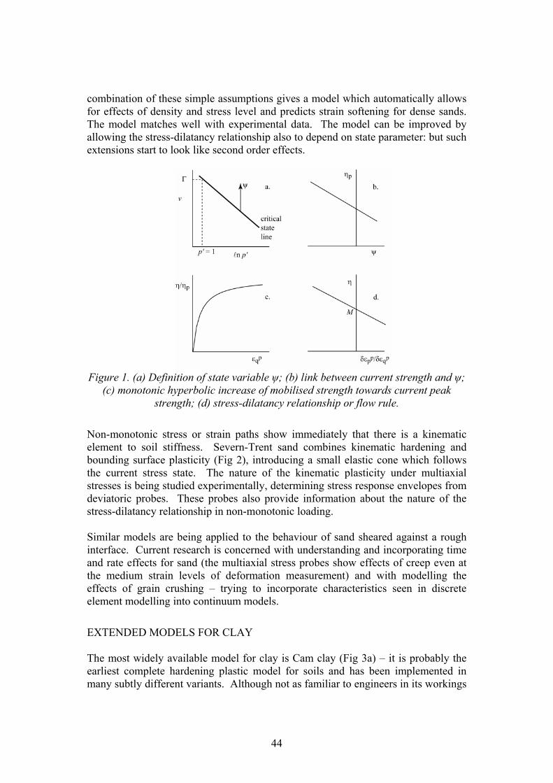
combination of these simple assumptions gives a model which automatically allows for effects of density and stress level and predicts strain softening for dense sands. The model matches well with experimental data. The model can be improved by allowing the stress-dilatancy relationship also to depend on state parameter: but such extensions start to look like second order effects.
Figure 1. (a) Definition of state variable ψ; (b) link between current strength and ψ;
(c) monotonic hyperbolic increase of mobilised strength towards current peak strength; (d) stress-dilatancy relationship or flow rule.
Non-monotonic stress or strain paths show immediately that there is a kinematic element to soil stiffness. Severn-Trent sand combines kinematic hardening and bounding surface plasticity (Fig 2), introducing a small elastic cone which follows the current stress state. The nature of the kinematic plasticity under multiaxial stresses is being studied experimentally, determining stress response envelopes from deviatoric probes. These probes also provide information about the nature of the stress-dilatancy relationship in non-monotonic loading. Similar models are being applied to the behaviour of sand sheared against a rough interface. Current research is concerned with understanding and incorporating time and rate effects for sand (the multiaxial stress probes show effects of creep even at the medium strain levels of deformation measurement) and with modelling the effects of grain crushing – trying to incorporate characteristics seen in discrete element modelling into continuum models.
EXTENDED MODELS FOR CLAY The most widely available model for clay is Cam clay (Fig 3a) – it is probably the earliest complete hardening plastic model for soils and has been implemented in many subtly different variants. Although not as familiar to engineers in its workings
44

as the perfectly plastic Mohr-Coulomb model it provides a useful basis from which to develop more advanced models. Non-monotonic loading shows kinematic plasticity – Al-Tabbaa and Muir Wood (1989) develop a kinematic hardening ‘bubble’ model as a direct extension of Cam clay (Fig 3b).
Figure 3. (a) Cam clay; (b) kinematic hardening extension of Cam clay: ‘bubble' bounds elastic region and moves with stress history; (c) addition of structure or
bonding to kinematic hardening Cam clay model
Natural clays have some structure or fabric with bonding between particles which is damaged by straining leading to sensitivity in in-situ and laboratory tests. We add structure (Rouainia & Muir Wood, 2000; Gajo & Muir Wood, 2001; Callisto et al., 2002) by expanding and shifting all elements of the ‘bubble’ model relative to a reference surface for the remoulded structureless material (Fig 3c), arguing that plastic strain must constitute damage and that remoulding is equivalent to massive continuing plastic straining. As implemented, damage has been purely linked to plastic strain – with provision for separate contributions of volumetric and distortional strain. However, the degree of structure could obviously be allowed to vary with time or coupled with analysis of chemical effects. Time might be expected to encourage bonding – perhaps on a geological timescale, perhaps faster. Chemical effects in the pore water might encourage precipitation around the grain contacts – and therefore increased bonding – or dissolution of the bonds – and therefore loss of structure or weathering. Current research is studying time effects in clays – aiming to add some viscoplastic component to the kinematic hardening models. PROMOTION OF USE OF ADVANCED NUMERICAL MODELS IN PRACTICE There are several steps that can be proposed to endeavour to increase the proper use of advanced numerical models (meaning advanced constitutive models) in practice.
i. Education, education, education! Ioannis Vardoulakis challenged some of us a few years ago to indicate what if anything from the past 50 years of research in soil mechanics had entered the undergraduate curriculum. If one is looking for topics that have received universal acceptance then the answer to that challenge is close to zero. However, I suspect
45

that the concepts of critical state soil mechanics (by which I do not mean Cam clay: Muir Wood, 2002) have been quite widely accepted. But it is unlikely that anything approaching even a simple soil model is introduced into the typical undergraduate degree programme. However, if we are to achieve greater understanding and appreciation of soil models then it is only by wide appropriate introduction at least into graduate programmes that we may meet with some success. The two books (Muir Wood, 1990; Muir Wood, 2004) are used for a final year optional unit within an undergraduate masters degree programme (a four year first degree) at Bristol (and were used similarly at Glasgow). These books try to define a syllabus that might be generally useful in educating engineers into the possibilities and problems of soil modelling. Such a syllabus can also be used for continuing professional development courses for practising engineers but the task of convincing them is probably greater.
ii. Keep it simple I am a great believer in adequate complexity in geotechnical modelling (Muir Wood, 2000). This implies that the user or commissioner of the modelling should have some idea of the phenomena that are expected to be important and can ensure that these phenomena, at least, are included in the modelling. I suppose that only experience can lead to a confident view about which aspects of soil response are first order and which second order so far as the performance of a geotechnical system is concerned. However, that experience can also be gained from careful parametric study.
iii. Build on familiar foundations I believe that engineers are more likely to make use of models which can be clearly seen as incrementally different from ones with which they have some familiarity than to make use of models which adopt a completely different language. On the one hand certain plausible soil models (with minor variations) are more or less generally available in geotechnical numerical analysis programs – some even in programs which are intended for wider engineering application. On the other hand some models can be readily developed from the teaching on soil strength that is a part of every undergraduate programme. Elastic-perfectly plastic Mohr-Coulomb models fall into both categories and it is for this reason that one of the hierarchical sets of models that we have developed is built up naturally from the very basic (and inadequate) elastic-perfectly plastic Mohr-Coulomb model. Cam clay (in some form) also appears in many numerical programs and thus also naturally forms the basis for another hierarchical set of models. However, the undergraduate background for Cam clay is less ubiquitous.
iv. Unification not disintegration The second book (Muir Wood, 2004) developed from an industrial secondment during which I was working with the structural engineering division of a probably typical company. There is a tendency for separate structural and geotechnical groups to wish to retain project ownership and ask, without defining context, for information on the parameters that they feel are important. We must plead guilty in universities too: from the first year of a typical civil engineering degree programme there are separate units in structures, soil mechanics, hydraulics and little effort
46

made to introduce unifying units which require a combined appreciation of two or three of these subjects. Soil-structure interaction is an obvious vehicle for such unification since situations can be readily constructed where the system response can only be understood with simultaneous knowledge of the behaviour of both the structural and the geotechnical materials. An example is provided by the analysis of an integral bridge abutment (Fig 4b) (Muir Wood & Nash, 2000; Muir Wood, 2004). The simplistic structural approach supposes that the thermal expansion of a bridge deck forces the abutment to move into the backfill in a passive mode: therefore the controlling parameter that is demanded of the geotechnical engineers is an angle of friction for the backfill. An analysis of the complete system of structure and backfill shows that in fact the strength of the backfill has almost no effect on the structural performance (maximum bending moment, etc) and that it is relative stiffness of structural material and backfill which determines the result because the typical stress paths for elements in the backfill are moving away from failure (Fig 4a) which, using a simple elastic-perfectly plastic Mohr-Coulomb model, implies purely elastic response. Understanding this, the structural stress resultants are greatly reduced and considerable economies ensue. Examples such as this can help to convince by demonstration the benefits of using realistic soil models.
Figure 4. (a) Stress path for typical element in backfill behind (b) integral bridge abutment.
There is also separation between those who relish sitting in front of a computer screen and those who want to get on with the engineering. Many of the dangers of advanced modelling arise from lack of proper communication between and integration of these groups.
v. Develop respect However, at the same time as we try to encourage greater understanding of soil models, and consequently greater use of numerical analysis programs in which they feature, we need to encourage respect for numerical modelling. The messages
47

contained in Potts’ Rankine Lecture (2003) are salutary. He is probably too pessimistic, proposing that numerical analysis should be left exclusively to the experts. A more optimistic academic view is that it should be possible to teach engineers about the difficulties and dangers of numerical modelling, again by demonstration, in such a way that they are not frightened off but actually become more confident in what they are doing. Education seems again to be a necessity.
References Al-Tabbaa, A and Muir Wood, D (1989) An experimentally based "bubble" model for clay. Numerical Models in Geomechanics NUMOG III (eds S Pietruszczak and GN Pande) Elsevier Applied Science 91-99. Been, K and Jefferies, MG (1985) A state parameter for sands. Géotechnique 35 2, 99-112. Callisto, L, Gajo, A and Muir Wood, D (2002) Simulation of stress probe tests on natural and reconstituted Pisa clay Géotechnique 52 9, 649-666 Gajo, A and Muir Wood, D (1999a) A kinematic hardening constitutive model for sands: the multiaxial formulation. International Journal for Numerical and Analytical Methods in Geomechanics 23 925-965. Gajo, A and Muir Wood, D (1999b) Severn-Trent sand: a kinematic hardening constitutive model for sands: the q-p formulation. Géotechnique 49 5, 595-614. Gajo, A and Muir Wood, D (2001) A new approach to anisotropic, bounding surface plasticity: general formulation and simulations of natural and reconstituted clay behaviour. International Journal for Numerical and Analytical Methods in Geomechanics 25 3, 207-241. Muir Wood, D (1990) Soil behaviour and critical state soil mechanics. Cambridge University Press (462pp) Muir Wood, D (2000) The role of models in civil engineering. Constitutive modelling of granular materials (ed D Kolymbas) Berlin:Springer-Verlag 37-55 ISBN 3-540-66919-1 Muir Wood, D (2002) Constitutive cladistics: the progeny of Critical State Soil Mechanics. Constitutive and centrifuge modelling: two extremes (ed S Springman) Swets & Zeitlinger, Lisse 35-58. ISBN 90 5809 361 1 Muir Wood, D (2004) Geotechnical modelling. E. & F.N. Spon (488pp) Muir Wood, D and Nash, DFT (2000) Earth pressures on an integral bridge abutment: a numerical case study. Soils and Foundations 40 6, 23-38. Potts, DM (2003) Numerical analysis: a virtual dream or practical reality? (42nd Rankine Lecture). Géotechnique 53 6, 535-573. Rouainia, M and Muir Wood, D (2000) A kinematic hardening constitutive model for natural clays with loss of structure. Géotechnique 50 2, 153-164.
48

Unified Effective Stress Concept for Unsaturated Soils
Ning Lu
Division of Engineering, Colorado School of Mines, Golden CO, USA
Abstract One of the major obstacles in dealing with practical geotechnical problems in unsaturated soils is the definition of effective stress and strength. My 5-minute presentation will discuss a unified effective stress concept to define stress in both saturated and unsaturated soils. The experimental verification of the unified effective stress as well as the simplicity to determine it will also be demonstrated. The unified effective stress concept does not need to redefine shear strength of unsaturated soils, and is consistent with the failure and deformation mechanisms in the classical soil mechanics for saturated soils. The practical implication is that many classical soil mechanics theories such as earth pressure, bearing capacity, and slope stability analysis are readily to be adopted for practical unsaturated soil problems.
49

Two-Surface Soil Constitutive Model Calibration For Coarse
Granular Materials
Pedro Arduino
Department of Civil Engineering, University of Washington, Seattle WA, USA Abstract In recent years, the use of numerical tools in geotechnical engineering has increased dramatically, both in research and practice. Among possible numerical tools the finite element method has proven to be an efficient technique for the analysis of geotechnical problems. With the advancement of constitutive models for soils, what used to be an academic exercise is becoming a common state of practice. Today, practical design and research in geotechnical engineering rely not only on experimental and field evidence, but also on advanced numerical simulations largely based on finite element solutions. This has been possible due to an extensive and continuous research effort on the development of accurate constitutive models for soils. Most of today's research efforts in this area concentrate on the validation, efficient implementation, and calibration of three-dimensional constitutive models for soils. This paper presents a calibration study aimed at evaluating a recently developed constitutive model for coarse granular materials. It is well known that numerical models only capture certain aspects of a physical reality and that a thorough calibration process is required to reduce the gap between numerical simulations and the reality under investigation. Here, the physical reality refers to true-triaxial test results for pea-gravels and the numerical model refers to the two-surface constitutive model proposed by Manzari and Dafalias (1997). This model is a fully three-dimensional time independent model mainly controlled by back-stress ratios associated with bounding, critical and phase-transformation surfaces. To account for irreversible response, the model is formulated based on classical plasticity theory for cohesionless soils including an associative flow rule for the deviatoric component and a nonassociative flow rule for the volumetric part. Dilation is controlled by a state parameter defined in terms of current and critical void ratios. One of the advantages of the model is its capability to capture with a single set of model parameters the qualitative behavior of cohesionless soils under drained and undrained conditions, different void ratios and confining pressures, and general loading conditions. In this study the response of gravelly soil subjected to complex stress paths is considered. Stress paths used in the calibration process include: (1) monotonic stress
50

paths in a deviatoric plane, (2) cyclic simple shear (SS) stress path, and (3) circular cyclic stress path on a deviatoric plane with varying Lode angle and constant mean stress. Comparisons of the model simulations to the experimental results show that the model is capable of capturing the behavior of pea-gravel under monotonic and cyclic loading conditions.
51

Mathematical Models for Geo-Engineering Practice: Big Projects and Constitutive Parameters are the Key
Tomasz Hueckel
Department of Civil and Environmental Engineering, Duke University, Durham
NC, USA Abstract PART 1: CHEMO-MECHANICS OF SOILS. Chemo-mechanics is defined as coupled fluid and solid mechanics of geomaterials, when processes of transport (flow), chemical reactions, deformation and failure influence each other. The formulation of the problems in this area rests on a series of couplings between elastic, plastic, hydraulic, diffusional, chemical-reactions, physico/chemical phenomena as well as thermal influence. The applicability of the developments is fairly extended. There are many common day geotechnical problems, which could be helped by a proper understanding and hence modeling of chemo-mechanical phenomena. It is enough to open J. K. Mitchell’s book to see the variety and quantity of problems that involve chemical considerations as a necessary step. These include not only the problems where an explicit chemical load occurs (contamination of hydraulic barriers, flooding with water with non-indigenous chemistry, causing swelling,) but also problems where chemistry is not explicit, but triggers “hidden phenomena” (creep, aging, weathering, chemical erosion). Examples of the constitutive coupling include effects of contamination on permeability of impoundment liner, effect of increase of pore water acidity on mineral dissolution, which may critically weaken the materials strength, effect of change in salinity of pore water on swelling or shrinkage of expansive clays used as a road bed, role of water in intergranular contact dissolution in compaction of oil reservoir and many others. While most of these instances of chemistry dependence were recognized and known to a various degree for sometime, new questions arise when these processes are to be quantified and mathematically modeled. Chemical reactions, controlled by phenomena of creation or demise of chemical compounds, are opposed here to physico-chemical phenomena of flocculation, peptization, swelling, which are caused by changes in van der Waals, or other electro-chemical forces, such as in electrolytes (e.g. pore water in active clays). The main issue of concern in chemo-mechanics of soils is when chemically driven processes of loss of mass of soil/rock components produce a decline in strength and/or stiffness, and/or possibly an increase in permeability or when changes in pore fluid chemistry produce physico-chemical phenomena with the same results.
52

In the problems of coupled chemo-mechanics the principal role is played by changes in mass of specific components of the solid or fluid phase, as during dissolution of a particular mineral. Consequently, first, either explicitly or implicitly, both solid and fluid phases are to be considered as multi-component (or multi-species). Second, mass or relative mass, or rates of all, or selected, crucial species become critical variables. Computational chemistry is indeed involved in calculating mass change of components and products during reactions and or physico-chemical processes, and possibly (advective and/or diffusive) transport. Mass changes of each species are subjected to mass balance law constraint. Oftentimes, the number of species involved in the reactions is high. Therefore, the number of equations that would result from considering balance laws for each species, including momentum balance with partial stresses associated with each species, becomes prohibitively high. One way out of that trouble is to limit the number of species to a lowest physically justifiable number. Another way is to adopt Kestin-Bataille (1977) postulate of strongly interacting mixtures, where no momentum balance is imposed on species, just that of mass. Momentum balance is then applied only to phases. Species are constrained only by the mass balance and flux constitutive laws. In general, each phase may contain some chemical species, which move independently and which may take part in chemical reactions or physico-chemical processes within a phase or between the phases. We have extended this postulate implying that only phases (and not species) are subjected to partial stresses and strain and thus are endowed with mechanical properties, as compressibility, plasticity moduli, strength and permeability (Hueckel, 2002). The effect of mass change of a component (including that of concentration of a solute in pore water) on mechanical/hydraulic properties of soil is reproduced by extending mechanical constitutive laws to include chemical variables, such as reversible and irreversible part of the mass change, or the corresponding chemical potential. In parallel, chemical constitutive laws are extended to include mechanical variables, such as specific the interphase surface area from which dissolution proceed, affected by mechanical damage. PART 2. USE OF ADVANCED NUMERICAL MODELS IN GEOTECHNICS. In my assessment there are two reasons for a low usage of numerical models in geotechnical engineering. One stems from a chaotic approach to the determination of material constants which is unfortunately a common practice in geomaterial modeling. Potential users are often left without specific instructions about the meaning of the parameters and without standard procedures to calculate them from experiments or field tests. This often leads to the perception that there is no sufficient experimental and/or physical substantiation of the model. The other cause appears to me to derive from a low familiarity of the geotechnical engineering community with mathematical models, good mechanics of materials, numerical procedures and directly with finite element codes. This situation arises from a low content of both programming and usage of FE codes in the classroom
53

teaching. It is generally justified by the belief that students are either unprepared theoretically for the use of models, or should be exposed to numerical work at earliest at the masters degree level, if at all. However, even at the master level the numerical work in geotechnical engineering is not given any significant emphasis. It appears that mathematical modeling at a more advanced level is almost routinely considered to be appropriate for doctoral work specialized in the area of geomechanics, while geotechnical engineering is still believed to be experimental, empirical or in situ oriented area. From my experience and from talking to international colleagues, this situation is observed also in other countries. It has been for long time maintained in the community that one of the shortcomings of the US based civil engineering, and not only geomechanics related sciences is its scarcity of the financial support of the civil engineering industry. The lack of current major civil engineering projects (dams, new highway systems, ... etc) of national importance and fragmentation of the industry are believed to be the causes. May be the rebuilding of the Gulf coast will provide some impetus. However, it must be underlined that even the existing US DOE and NASA related projects of a substantial weight nationally (e.g Yucca Mountain project) did not spark any intense progress in development of mathematical modeling in geomechanics comparable to the enormous European or Japanese effort in this area. It is clearly a characteristics of the US DOE program. The tendency of National Laboratories to rely on home-grown and certified codes only, lead often to a forced use of programs that are ten or more years old. This on the one hand, severely reduces the possibility of academic public scrutiny of the work in the areas of vital national importance, and on the other does not stimulate the progress in these areas. In my opinion a driving force for a greater usage of advanced models should come from special projects. To achieve that goal we need to influence the decision makers about validity of our models. Geologists, geochemists, even physicist do it, we should do it as well. Another are of expansion of geomechanical modeling is the foundation engineering practice. In this case the effort needs to be made in my opinion to raise the appreciation of usefulness of the modeling across the geotechnical community, as well as raise the confidence in prospective results. WHAT TO DO?
1. Teach undergraduate students basic plasticity models, including Cam Clay. 2. Encourage the use of numerical analyses using Finite Element Methods in
the undergraduate geotechnical engineering classes 3. Encourage the use of mathematical modeling in the graduate geotechnics
(not only geomechanics) classes as a part of required (core) course education
54

4. Find the ways that the nuclear waste disposal industry as well as other DOE, NASA,petroleum industry – promoted initiatives (carbon sequestration, methane hydrates) stimulate the development of new and use of the existing advanced mathematical models.
Problems that require advanced geomechanics models. Over recent years the area of environmental geomechanics received a substantial attention of model developers. I have actively participated in this work developing models of soil thermo-plasticity, chemo-plasticity, at constant and variable saturation conditions. The thero-plasticity models became now a standard for applications in nuclear waste disposal projects in clay rocks, argillites or with remolded bentonite buffers that are under consideration in France, Belgium, Japan and Switzerland. There is now also an effort made to include chemical effects on soil mechanical behavior, inclusive of swelling due to salinity change of pore water in nuclear waste barriers, contamination by hydro-carbons and acids, as well as effects of weathering and chemical erosion attract also attention. A unifying theme in these areas of modeling is their very close relation with an intense experimental work, as many of the phenomena addressed are poorly understood or insufficiently tested. Specific constitutive problems that were addressed until present using the above described approach include:
• chemo-plastic consolidation of clays upon thermal removal of adsorbed water, (Hueckel, 1992)
• thermal re-smectitization (Hueckel, 2002) • chemo-plastic consolidation of clay liners upon ethanol contamination,
(Hueckel, 1997) • swelling/collapse upon ion density (salt) decrease/increase/exchange • (Loret et al., 2001,2002) • permeability increase upon ethanol contamination (Hueckel, 2004) • aging as inter-grain contact dissolution (Hueckel et al., 2001, Hueckel&
Hu, 2004, 2006) • creep as chemically enhanced damage (Hu & Hueckel, 2005) BVPs: • Chemo-consolidation-contamination (Kaczmarek and Hueckel, 1999) • Swelling-collapse-ionic strength, exchange (Gajo & Loret, 2003) • Shear banding, tunnel swelling, consolidation due to contamination with
ion strength (Liu et al., 2005)
References Hu, L. 2004, Chemo-mechanical Coupling at the Intergranular Contact: a Microscopic Prototype Model, M. Sci. Thesis, Pratt School of Engineering, Duke University
55

Hueckel T. and M. Borsetto, 1990, Thermoplasticity of Saturated Soils and Shales: Constitutive Equations, Journal of Geotechnical Engineering, ASCE, 116, 12, 1765-1777 Hueckel, T. A., 1992, Water - Mineral Interaction in Hygro-Mechanics of Clays Exposed to Environmental Loads: a Mixture Theory Approach, Canadian Geotechnical Journal, 29, 1071-1086 Hueckel, T., M. Kaczmarek and P. Caramuscio, 1997, Theoretical assessment of fabric and permeability changes in clays affected by contaminants, Can. Geot.J.,34, 588– 603 Hueckel, T., 1997, Chemo-plasticity of Clays Subjected to Flow of a Single Contaminant and Stress, Int.J. for Numerical and Analytical Methods in Geomechanics, 21, 1, 43 – 72 Hueckel, T., F. Tao, G. Cassiani and A. Pellegrino, 1999, Reactive plasticity for geological materials with a double structure evolving during aging, in Const. Laws for Eng. Mat.s, R.C. Picu and E. Krempl, eds. 383–387 Hueckel, T., G. Cassiani, Fan Tao, A. Pellegrino and V. Fioravante, 2001, Aging of Oil/gas Bearing Sediments, their Compressibility and Subsidence, Journal of Geotechnical and Geoenv. Engineering, ASCE, 127, 11, 926 - 938Hueckel, T. 2002, Reactive Plasticity for Clays during Dehydration and Rehydration. Part I: Concepts and Options, International Journal of Plasticity, 18, 3, 281 – 312 Hueckel, T., B. Loret and A. Gajo, 2002, Expansive clays as two-phase, deformable, reactive continua: concepts and modeling options, in “Chemo-mechanical coupling in clays: from nano-scale to engineering applications” C. Di Maio, T. Hueckel and B. Loret, eds Swets and Zetlinger, Lisse, The Netherlands, 105 - 120 Hueckel T., 2004, Coupling variable permeability to strain and mass transfer in contaminated clays, Computational and Experimental Engineering and Sciences, ed. by Atluri, R.S. Hueckel T. and L.B. Hu, 2004, Chemo-mechanical coupling and damage enhanced dissolution at intergranular contact; in Numerical Models in Geomechanics, G.N. Pande and S. Pietruszczak, eds., Balkema, Rotterdam, 349-353 Hueckel, T., 2005, A key issue in chemo-mechanical coupling in environmental geomechanics: modelling across the scales, in Computer Methods and Advances in Geomechanics, G.& M. Barla, eds., Patron Edit. Turin, It., 4, 531-541 Loret, B. T. Hueckel, A. Gajo, 2002, Chemo-mechanical coupling in saturated porous media: elasto-plastic behaviour of homoionic expansive clays, International Journal of Solids and Structures, 39, 2773-2806 Z. Liu, N. Boukpeti, X. Li, F. Collin, J-P. Radu, T. Hueckel and R. Charlier, 2005, Modelling chemo-hydro-mechanical behaviour of unsaturated clays: a feasibility study, Int. J. for Num. and Anal. Methods in Geomechanics, 29, 919-940.
56

Sliding/Rolling Constitutive Model and Its Generalization
Rajah Anandarajah
Department of Civil Engineering Johns Hopkins University, Baltimore, Maryland
Abstract The past three decades have seen an intense research in all aspects of nonlinear modeling of geotechnical problems. However, there has not been a concerted effort in promoting the use of advanced procedures that resulted from the past research to solve real world problems that these procedures are intended for. Due to the complexity of the advanced methods and the inherent complexity of soils (complexity of stress-strain behavior, heterogeneity, boundary conditions, etc.), this transfer of knowledge from theory to practice is non trivial. The solution to this problem must involve a multi-faceted approach, with researchers and practitioners working together to achieve clear goals. Some of these ideas and examples of efforts taken at our institution will be discussed in this talk. Specifically, the aspects of model calibration through in situ testing will be discussed. Another key aspect concerns the complexity of constitutive models and the physical meaning for functions and parameters. For practitioners to feel comfortable with the values of parameters to use as input into the advanced solution methods, they must be able to relate its value to some basic characteristics of the soil they have in hand; for example, the gradation, the angularity, inter-particle friction, pore fluid composition, mineral type, etc. One way to achieve this is to start the process of constitutive modeling from micro-structural considerations and build up the macroscopic models that are eventually needed in finite element analyses. In this regard, we have conducted microscopic studies both in clays and sands. Some of these ideas will also be discussed in this talk. For sands, based on microscopic considerations of inter-particle sliding and rolling, a macroscopic constitutive framework has recently been pursued. First, the framework was developed for a two-dimensional assembly of granular particles. The discrete element method was then used to develop understanding needed for extending the two-dimensional framework for triaxial loading conditions. Currently methods are developed for generalizing the triaxial framework to perform general three-dimensional stress-strain simulations. These ideals will also be discussed.
57

Probabilistic analysis by the random Finite Element
Method: A more rational approach to decision making in geotechnical analysis and design
D.V. Griffiths
The presentation seeks to promote probabilistic tools as a more rational approach to geotechnical analysis and design than the traditional “factors of safety” approach. The presentation describes a powerful method for probabilistic geotechnical analysis called the Random Finite Element Method (RFEM). The method involves a combination of the finite element method and random field theory in a Monte-Carlo framework. The RFEM takes full account of spatial correlation and local averaging. The method has been applied to numerous areas of classical geotechnical analysis (see www.engmath.dal.ca/rfem/rfem.html for a summary of publications), however this presentation will concentrated on slope stability analysis. Attention is first drawn to the sensitivity of the Factor of Safety in some slope problems, to the assumed shape of the failure surface even using traditional methods (e.g. Bishop vs. Spencer). Examples are given of slope stability analysis using the elasto-plastic FE, which makes no a priori assumption about the shape or location of the failure surface. The method naturally finds the critical failure mechanism, and hence the "minimum" factor of safety by allowing a slope to "fail where it want to fail". Examples will be given where an incorrect (and unconservative) Factor of Safety can be predicted by classical methods if the wrong search strategy is adopted. The benefits of the RFEM approach to slope stability analysis and its ability to "seek out" the critical mechanism, are even more important in probabilistic analysis of highly variable soils. In this case, the presence of strong and weak soils occurring in the same slope, implies that the shape and location of the failure surface is quite unpredictable. In some cases, the failure mechanisms given by the RFEM approach in such soils are so complex, that meaningful analysis using classical slope stability would be impossible. It is argued that even with proper local averaging, probabilistic slope stability analyses based on traditional methods are flawed in that they are based on failure mechanisms that are unlikely to be critical. The RFEM represents one of the very few methods able to perform qualitative probabilistic geotechnical analysis in an objective and fundamental way.
58

Part 2: Education is the key to more widespread and appropriate use of nonlinear modeling in geotechnical practice. Five steps that may promote the use of advanced models in geotechnical practice: 1. A more unified approach to the way introductory Soil Mechanics is taught
at college. This requires a breaking of the mould by which Soil Mechanics textbooks continue to be written. One problem lies in the treatment of deformation and failure as if they were entirely different soil mechanics topics (different Chapters of the book etc.), as opposed to just different locations on the same stress-strain curve. The traditional approach detracts from the idea of utilizing a soil model that is able to describe the response of soil from small strains all the way through to collapse.
2. More professional level short courses need to be offered by Academic/practitioners. In these courses the benefits of advanced techniques and models should be promoted in the context of classical soil mechanics, using a language that is not intimidating. Education is needed in the terminology of constitutive modeling, e.g. what is meant by a “plastic potential”, or a “Drucker-Prager model”?
3. Which geotechnical problems actually “need” an advanced model? Soil is
one of the most complex of all engineering materials, so many simplifying assumptions need to be made. There are “models” with numerous parameters that claim to be able to “do everything”, however the majority of geotechnical analyses do not require all the model features. For example, the majority of settlement predictions can be made using a properly calibrated elastic analysis. Similarly, collapse problems of slope stability or bearing capacity, primarily require good failure models and representative strength parameters. We need to educate students and practitioners to properly understand which features of a model are needed and when.
4. The amazing growth of computer power coupled with falling costs. The use
of numerical tools like the finite element method should no longer be intimidating to geotechnical practitioners with the amazing growth of computer power coupled with falling costs. The average lap-top is now capable of performing advanced nonlinear geotechnical analysis. Three-dimensional analysis is now a realistic option for many problems, removing our historical dependence on plane strain. Education is needed in how the finite element method works and how it can be applied to new and challenging geotechnical problems. An appreciation of the huge potential (and pitfalls) of numerical method will help users to appreciate the benefits of constitutive modeling. Without better training, the danger remains that “package” based proprietary software will be operated by engineers with no appreciation of how it works
59

An Elasto-Plastic Model for Soft Geomaterials
Roberto Nova1
INTRODUCTION
Consider remoulded clay or freshly deposited (‘virgin’) sand specimens. When one of these is subjected to a cycle of loading-unloading and reloading, some common features of the experimental results can be observed: a) soil behaviour is non-linear and irreversible, i.e. only part of the strains
occurring in the loading phase can be recovered upon unloading; b) in a cycle of unloading-reloading, instead, the observed behaviour is more or
less reversible and characterised by a larger stiffness than upon virgin loading; c) when the stress state reaches the level at which unloading started, a marked
stiffness change is observed and the soil behaves as it would be virgin, i.e. as if the unloading-reloading cycle would have not been performed;
d) furthermore, soil behaviour is very much sensitive to the value of the isotropic effective pressure at which it is tested, i.e. stiffness and strength depend very much on it.
The simplest way to cope with such observations is to assume that soil behaviour can be considered as elastic-plastic with hardening, as initially conjectured by Drucker et al (19957). On these premises the School of Cambridge (see e.g. Schofield and Wroth (1968)) built the successful model known as Cam Clay. MODEL FOR UNCEMENTED SOILS An elastic-plastic model is essentially based on four ingredients: a) an elastic law valid within the elastic domain that is a region of the stress space
delimited by a surface known as yield locus b) an expression for the loading function. This is a function of the stress state that
defines when permanent (or plastic) strains occur. The yield locus is in fact given by the locus of the points for which the loading function is zero
c) an expression of the plastic potential that governs the way plastic strains develop d) an expression for the hardening law that controls the size of the plastic strains. The model that was employed to simulate the test results that are presented in the following is based on convenient expressions for all the aforementioned functions. Their actual expression can be found in various papers (e.g.Nova (1988), Nova (1992)) A short model presentation can be found in a recent paper (Nova (2005)).
1Professor, Milan University of Technology (Politecnico) Piazza Leonardo da Vinci,32 20133 Milano - ITALY
60

The constitutive law is characterised by 7 non-dimensional parameters and a reference pressure pco. The plastic potential is characterised by the single parameter g , directly linked to the mobilised friction angle at constant volume, 'cvφ : The loading function is characterised by and . The latter controls the deviation from normality, due to the spherical part only. If = 3 normality holds. This parameter can be then determined by fitting the calculated curve to the data of the drained test.
g bb
Hardening depends on three parameters: Bp, x and . The first one indicates the logarithmic volumetric plastic compliance under isotropic loading. The parameters
y
x and control the value of dilatancy at failure in compression and extension. yThe hypoelastic parameters are eB and L . The first is similar to pB , but relative to
the volumetric compressibility in isotropic unloading-reloading.The other elastic parameter L is linked to the shear modulus G.
The value of pco is actually the most difficult parameter to be determined for virgin soils. It is in fact a fictitious dimensional parameter introduced only to avoid the singularities at the origin of axes, both for elastic and plastic moduli. Its precise value is important only for small stress levels.
MODEL PREDICTIONS
The model was initially developed to predict the behaviour of samples of two types of sand tested with two apparatus on occasion of the Cleveland Workshop on Constitutive Equations for Granular non-cohesive soils (Saada and Bianchini (1988)).
A comparison between the results predicted by means of the model presented (dotted curves) and the experimental data is shown in figures 1 and 2. In the first test, in the hollow cylinder, the shear stress and the normal stress vary proportionally, while in the second, in the cubic triaxial cell, the mean pressure and the b value are kept constant.
The model was also applied to describe the behaviour of remoulded clays and to simulate the behaviour of sand in undrained tests.
MODEL FOR CEMENTED SOILS
A successive modification (Nova 1992) allowed also the role of bonding to be taken into account, with the addition of two parameters only. They are linked to the tensile strength of the bonds. The main idea is that cementation generates an initial elastic domain that is independent of the confining pressure. Figures 3 show a comparison for experimental and calculated behaviour in undrained tests on chalk (after Nova and Lagioia (1996) – data after Leddra (1988)) after K0 consolidation. The value of the bonding parameters can change with the loading process or with the attack of chemicals, to simulate the effect that both phenomena have on bond breaking. A complete treatment of the problem is given in Nova et al. (2003). Fig 4 shows the prediction of the evolution of vertical strains in an oedometric test on a lime cemented silica sand specimen in which an acid was made to seep through, progressively dissolving the bonds.
61

REFERENCES Drucker, D. C., Gibson R. E. and Henkel D. J. (1957). “Soil Mechanics and
workhardening theories of plasticity” Trans. ASCE, 122, 338-346. Leddra, M.J.(1988).”Deformation on Chalk through compaction and flow”. PhD
Thesis, Univ. of London. Nova, R. (1988). “Sinfonietta classica: an exercise on classical soil modelling” Proc.
Symp. Constitutive Equations for Granular non- cohesive soils, Cleveland , A. Saada & G. Bianchini eds., Balkema, Rotterdam , 501-519.
Nova, R. (1992). “Mathematical modelling of natural and engineered geomaterials” general lecture 1st E.C.S.M. Munchen, European J. Mech. A/Solids, 11,Special issue, 135-154.
Nova, R.and Lagioia, R. (1996). “Soft Rocks: Behaviour and Modelling” Keynote lecture, Proc. Eurock ’96, Turin, Balkema 2000, 3, 1521-1540
Nova, R., Castellanza, R., Tamagnini, C. (2003). “A constitutive model for bonded geomaterials subject to mechanical and/or chemical degradation.” Int. J. Num. Anal. Meth. Geomech., 27(9),705-732
Nova R. (2005) A simple elastoplastic model for soils and soft rocks. In Soil constitutive models:Evaluation, Selection and Calibration ASCE, Yamamuro & Kaliakin eds. Geotechnical special pub.128, 380-399
Saada A. and Bianchini,G. eds. (1988). Constitutive Equations for Granular non- cohesive soils, Cleveland, Balkema, Rotterdam, pag 733.
Schofield A.N.and Wroth C.P. Critical State Soil Mechanics, McGraw Hill
62

FIG. 1. Silica sand. Comparison between predictions and actual test results – hollow cylinder apparatus after Nova (1988)
FIG. 2. Silica sand. Comparison between predictions and actual test results -cubic triaxial cell- after Nova (1988)
63

FIG.3. Undrained tests after K0 consolidation on Stevn’s Klint chalk: calculated results (above) from Nova and Lagioia (1996) and experimental data from Leddra (1988). a) stress strain relationship b) stress path
FIG.4. Lime cemented silica sand: oedometric loading followed by chemical attack at constant axial load and final unloading: variation of axial strain with time (after Nova et al. (2003)).

Modeling and Simulations for Geotechnical Problems
Boris Jeremić
Department of Civil and Environmental Engineering University of California
Davis, CA, 95616 [email protected]
http://sokocalo.engr.ucdaivs.edu/~jeremic
Abstract This short paper gives an overview of recent work by the Author and his research group in the area of modeling and simulations for geotechnical problems. The main thrust of our work is in a number of areas related to computational geomechanics, with a clear goal of applying developed methodologies and implementations for practical problems. Introduction The use of advanced numerical modeling techniques for problems in geotechnical engineering has not advanced at satisfactory pace when compared with other areas of Civil and Engineering in general. There are many reasons for that, some are technical in nature while the others are related to the inadequate preparation of students, researchers and practicing engineers to use such advanced tools. The technical set of challenges are dealt with through appropriate research (some of which is briefly described in this paper) while the inadequate preparation is much harder to tackle as it has to do with the fundamental change that needs to happen in geotechnical (and at some level in structural as well) engineering education. The (unfortunate) predominance of empirically based methods in geotechnical engineering is hard to explain without an in depth analysis of historical background and current design / construction practices. There are, of course, shining exemptions (from the overwhelming use of empirical methods) in professional practice and in the research community. However, these exemptions seem to be products of dedicated engineers and researchers rather than a product of our educational and professional practice system. Recent and Current Work within CompGeoMech Group at UCD The Computational Geomechanics group at UCD has in recent years developed a number of computational formulations and implementation that address many practical problems in geotechnical engineering. Most of this computational tools are build on top of the OpenSees finite element platform. This was made possible after merging of our previously developed nDarray and FEMtools libraries (eg. [1], [2]) with OpenSees framework, some five years ago.
65

More recently work has progressed in the area of dynamic soil-foundation-structure interaction, which encouraged development of a number of methodologies within the general computational geomechanics, some of which are briefly described below: • Template elasto-plasticity (e.g. [3]) is an approach to constitutive modeling and
elastic-plastic simulations based on the observation of similarity of many simple and advanced elastic-plastic model. Namely, most of them feature (1) yield function, (2) plastic flow directions and (3) evolution laws describing changes to (1) and (2). This similarity was used to develop a framework that allows development of new material models with relative ease, as well as their immediate use in finite element computations for static and dynamic simulations. The framework has been developed for both small and large deformations.
• Large deformation elastic-plastic analysis of geomaterials deserves special attention due to the inherent anisotropy of the material. The often used approach (e.g Simo [4], [5]) developed in principal directions of stress and strain measure cannot be used for anisotropic materials. Our alternative approach (e.g. [6], [7], [9]), developed in full stress and strain tensor space, proves to be more accurate and, more importantly, applicable to both isotropic and anisotropic materials.
• Behavior of soils in dependent on interaction of the solid (skeleton) and fluid (air or water in pores). This tight coupling necessitates development of fully coupled formulation for static and dynamic (slow and fast transient) simulations of soils. The high nonlinearity of coupling and of the skeleton behavior requires a robust verification and validation procedures (Jeremić et al, [21]) and an efficient implementation. Recent work at within the CompGeoMech group at UCD has shown that for most demanding Soil-Foundation-Structure Interaction problems, the u-p-U (u-displacements of skeleton, p-pore fluid pressure, U-displacements of fluid) formulation is most promising and has the highest accuracy.
• Dynamic soil-foundation-structure interaction (SFSI) has been focus of much research in recent past. Most importantly, there seems to be emerging a view that the SFSI is not necessarily beneficial to the structural behavior (as proclaimed by, for example, NEHRP-94 seismic code: ''These [seismic] forces therefore can be evaluated conservatively without the adjustments recommended in Sec. 2.5 [i.e. for SFS interaction effects]”. To this end, UCD CompGeoMech group has further developed Domain Reduction Method (e.g. Bielak et al, [10]) for inelastic SFSI simulations and have shown the SFSI can indeed be beneficial but also detrimental to the seismic response of structures (e.g. Jeremić et al. [11], [12], [13])
• Uncertainty in and non-uniformity of soil parameters (should) plays an important (this is an understatement) role in inelastic modeling and simulations of geotechnical problems. Lack of theoretical formulations and computational tools in this area has resulted in practicing engineers and researchers neglecting this rather important aspect of soil modeling. Our recent work (e.g. Jeremić et al. [14], [15], [16]) has laid foundation for further developments in this area. Some interesting (surprising) results are noted, for example, stochastic simulations using Cam-Clay material model, show that the most likely (mode) stress results can be quite a bit different than the deterministic solutions. This discrepancy puts current use of large safety factors for empirical and simple analytical methods in appropriate prospective.
66

• Geotechnical solids are inherently three dimensional and it is only our desire (need)
to save modeling and simulation efforts that drive us to resort to 1D and 2D simplifications. Only in rare circumstances can this reduction in dimensionality of the problem be justified, which means that we usually have to deal with large models. The large scale of (finite element) models used for geotechnical problem simulations require efficient analysis, which usually leads to parallel computing paradigm. The Parallel Domain Decomposition has recently been developed by the CompGeoMech group at UCD with specific focus on distributed memory parallel computations for elastic-plastic geomaterials (e.g. Jeremić and Jie [17]). The main advantage of the PDD over classical domain decomposition methods is in dynamic computational load balancing. This dynamic computational load balancing is required by the change in the extent of elastic and elastic-plastic domains and by the changing computational requirements on the constitutive (elastic-plastic) level of equilibrium iterations. The PDD is implemented on top of the OpenSees framework and is available for public use in source code. It runs on distributed memory parallel machines, which include local Beowulf clusters, and large parallel supercomputers.
• Design and creation of models (finite element meshes), including discovery of available models represents a very important phase of modeling and simulation in geotechnical and structural (and other branches of) engineering. There is an effort within CompGeoMech group at UCD to create (user friendly) set of computational tools (GUIs) that will allow practicing engineers to explore advanced simulation models without dwelling to much into the depth of inelastic FEM modeling. In addition to the (mostly) pre-processing efforts mentioned here, post-processing of simulation data usually constitutes the most time (and expertise) demanding stage of simulations. The large amount of simulation results (scalars, vectors and tensors) need to be visualized in hierarchic fashion, while allowing for data and feature discovery. This multitude of requirements posses a new set of challenges to numerical analysists, professional engineering users and visualization researchers (e.g. Jeremić [18], Hotz [19] and Neeman [20]).
Brief overview of our recent work lends itself to the inherent systems approach to modeling and simulations in geotechnical (and structural) engineering. Exclusive focus on narrow (yet very important) aspects of modeling and simulations in geotechnical (and structural) engineering, while certainly needed, will not help advance the case for more modeling and simulations. The advanced modeling and simulations of geotechnical (and structural) systems has yet to find its proper place in professional practice (and, more importantly, at the universities). It is anticipated (hoped) that in near future, high fidelity models of constructed facilities will live concurrently with the physical system they represent and provide owners and operators with the capabilities to assess operations and future performance. Moreover, observed performance will be used to update and validate models through simulations, which will be as accessible and user-friendly as some of the most successful programs we currently use on our desktop computers. It is hoped that this workshop is a step in that direction.
67

References [1] Boris Jeremić and Stein Sture. Tensor data objects in finite element programming. International Journal for Numerical Methods in Engineering, Vol. 41, pages 113-126, 1998. [2] Boris Jeremić and Stein Sture. Implicit integrations in elasto-plastic geotechnics. International Journal of Mechanics of Cohesive-Frictional Materials, Vol. 2, pages 165-183, 1997. [3] Boris Jeremić and Zhaohui Yang. Template Elastic-Plastic Computations in Geomechanics. International Journal for Numerical and Analytical Methods in Geomechanics, Vol. 26, Issue 14, pp 1407-1427, Dec. 2002. [4] J. C. Simo. A framework for finite strain elastoplasticity based on maximum plastic dissipation and the multiplicative decomposition: Part I. continuum formulation. Comp. Methods in Applied Mechanics and Engineering , 66:199-219, 1988. [5] J. C. Simo. A framework for finite strain elastoplasticity based on maximum plastic dissipation and the multiplicative decomposition: Part II. computational aspects. Computer Methods in Applied Mechanics and Engineering , 68:1-31, 1988. [6] Boris Jeremić, Kenneth Runesson and Stein Sture. Object Oriented Approach to Hyperelasticity. International Journal for Engineering with Computers, vol. 15(1), pages 2-12, 1999. [7] Boris Jeremić, Kenneth Runesson and Stein Sture. A model for elastic-plastic pressure sensitive materials subjected to large deformations. International Journal of Solids and Structures, vol. 36 No. 31/32 pages 4901-4918, 1999. [8] Boris Jeremić and Zhao Cheng. Significance of Equal Principal Stretches in Computational Hyperelasticity. Communications in Numerical Methods in Engineering, Vol. 21, Issue 9, pp 477-486, 2005. [9] Boris Jeremić and Zhao Cheng. Finite Deformation Hyperelasto-Plasticity in Intermediate and Current Configurations. Submitted to the Computer Methods in Applied Mechanics and Engineering, Fall 2005. [10] J. Bielak, K. Loukakis, Y. Hisada, and C. Yoshimura. Domain reduction method for three-dimensional earthquake modeling in localized regions. part I: Theory. Bulletin of the Seismological Society of America , 93(2):817{824, 2003. [11] Boris Jeremić, Sashi Kunnath and Feng Xiong. Influence of Soil-Structure interaction on Seismic Response of Bridges. International Journal for Engineering Structures, Vol. 26, Issue 3, February 2004, pp. 391-402. [12] Boris Jeremić, Sashi Kunnath and Matthias Preisig. On Benefits/Detriments of Soil-Foundation-Structure Interaction to Dynamic Behavior of Simple Stuctures. Submitted to the International Journal for Engineering Structures, 2005. [13] Boris Jeremić, and Matthias Preisig. On Inelastic Soil-Foundation-Structure Interaction Modeling and Simulations. Submitted to the Soil Dynamics and Earthquake Engineering, 2005. [14] Boris Jeremić, Kallol Sett and M. Levent Kavvas. Probabilistic Elasto-Plasticity: Formulation of Evolution of Probability Density Function. Submitted to the ASCE Journal of Engineering Mechanics, 2005. [15] Boris Jeremić, Kallol Sett and M. Levent Kavvas. Probabilistic Elasto-Plasticity: Solution and Verification of Evolution Equation of Probability Density Function. Submitted to the ASCE Journal of Engineering Mechanics, 2005. [16] Kallol Sett, Boris Jeremić and M. Levent Kavvas. The Role of Nonlinear Hardening in Probabilistic Elasto-Plasticity. Submitted to the Computer Methods in Applied Mechanics and Engineering, 2005. [17] Boris Jeremić and Guanzhou Jie. The Plastic Domain Decomposition Method for Parallel, Elastic-plastic Computations. To be submitted to the International Journal for Numerical and Analitical Methods in Geomechanics. 2005 [18] Boris Jeremić, Gerik Scheuermann, Jan Frey, Zhaohui Yang, Bernd Hamman, Kenneth I. Joy and Hans Haggen. Tensor Visualizations in Computational Geomechanics. International Journal for Numerical and Analytical Methods in Geomechanics , Vol 26. Issue 10, pp 925-944, August 2002. [19] Ingrid Hotz, Louis Feng, Hans Hagen, Bernd Hamann, Boris Jeremić, and Kenneth Joy. Physically Based Methods for Tensor Field Visualization IEEE Visualization 2004 Conference (Vis04), Austin, Texas, October 10-15 2004. [20] Alisa Neeman, Boris Jeremić and Alex Pang. Visualizing Tensor Fields in Geomechanics. IEEE Visualization Conference (Vis{05), October 23-28, 2005 Minneapolis-Saint Paul, Minnesota.
68

69

Experimental and Computational Modeling of Unsaturated Soil Response Under True Triaxial Stress States
Laureano R. Hoyos
University of Texas at Arlington, Arlington, Texas, USA
Abstract In the last few decades, the description of the stress-strain-strength behavior of unsaturated soils has been closely linked with efforts to isolate the relevant effective stress fields governing the soil’s mechanical response. By adopting matric suction, (ua – uw), and the excess of total stress over air pressure, (σ – ua), as the relevant stress state variables, various key features of unsaturated soil behavior have been modeled via controlled-suction oedometer, direct shear, and triaxial testing (e.g., Alonso et al. 1990, Wheeler and Sivakumar 1992, Fredlund and Rahardjo 1993). However, the majority of these devices allow for the application of loads along limited paths and modes of deformation, such as one-dimensional, hydrostatic, or axisymmetric loading. In nature, subgrade and shallow foundation soils located above the ground-water table are subjected to three-dimensional stress gradients due to changes in the stress state variables (σij – uaδij) and (ua – uw)δij, as depicted in Fig. 1. Therefore, the accurate prediction of stress-strain response of geosystems involving unsaturated soils requires that the soil constitutive relations be valid for all the major stress paths likely to be experienced in the field. It is in this context that a true triaxial cell, capable of inducing a wide range of suction-dependent multi-axial stress states in the test specimens, plays a fundamental role in the complete stress-strain-strength characterization of this type of materials.
Traffic load
(ua – uw)(σ1 – ua)
(ua – uw)(σ2 – ua)
(σ3 – ua) (ua – uw)
Pavement
Foundation load
(ua – uw)(σ1 – ua)
(ua – uw)(σ2 – ua)
(σ3 – ua) (ua – uw)
Traffic load
(ua – uw)(σ1 – ua)
(ua – uw)(σ2 – ua)
(σ3 – ua) (ua – uw)
Pavement
Foundation load
(ua – uw)(σ1 – ua)
(ua – uw)(σ2 – ua)
(σ3 – ua) (ua – uw)
Fig. 1. Unsaturated soil deposits under true triaxial stress states. In this brief workshop presentation, an implicit integration algorithm will be introduced with the aim of simulating constitutive response of unsaturated soils along controlled-suction, multi-axial stress paths that are not achievable in a conventional cylindrical apparatus. The algorithm supports numerical analyses in a deviatoric plane (π-plane) by using a mixed control constitutive driver, in conjunction with a Generalized Cam-Clay model, within a constant-suction scheme, incorporating the influence of a third stress invariant or Lode-angle θ.
69

True triaxial data from a series of controlled-suction triaxial compression, triaxial extension, and simple shear tests, conducted on cubical specimens of silty sand, are used for the tuning and validation of the implicit algorithm. The Willam-Varnke surface, along with the generalized Barcelona model, was used for simulation of soil behavior in three-invariant stress spaces, such as the p-q-θ (mean stress-deviator stress-Lode angle) space or octahedral stress space. Pleasant agreement was observed between experimental and predicted deviatoric stress versus principal strain responses for different suction states, as well as between experimental and predicted failure surfaces on the π-plane. The observed agreements have highlighted the potential of the implicit algorithm implemented herein for the analyses of geotechnical boundary-value problems involving large soil deposits that remain under partially saturated conditions throughout the year. The last few minutes of the presentation will be devoted to describing a novel true triaxial apparatus that has been developed to test 3-in side, cubical specimens of unsaturated soil under controlled-suction states for a wide range of stress paths that are not achievable in a conventional cylindrical apparatus. The new cell is an upgraded version of the one reported by Hoyos (1998), featuring two independent pore-air and pore-water pressure control systems via a PCP-5000-UNSAT pressure panel. Matric suction states in the specimens are induced during testing using the axis-translation technique. The device is being developed under National Science Foundation Award # 0216545. This support is gratefully acknowledged. References Alonso, E.E., Gens, A., and Josa, A. (1990). “A Constitutive Model for Partially Saturated Soils”. Géotechnique, 40(3), pp. 405-430. Fredlund, D.G., and Rahardjo, H. (1993). Soil Mechanics For Unsaturated Soils. John Wiley & Sons, Inc., NY. Hoyos, L.R. (1998). “Experimental and Computational Modeling of Unsaturated Soil Behavior Under True Triaxial Stress States”. Ph.D. dissertation, Georgia Institute of Technology, Atlanta, GA, 352 pp. Wheeler, S.J., and Sivakumar, V. (1992). “Development and Application of a Critical State Model for Unsaturated Soils”. Predictive Soil Mech., Eds: G.T. Houlsby and A.N. Schofield, pp. 709-728, London.
70
Need for Integrated Interpretation of In-Situ Tests
Paul W. Mayne, PhD, P.E.
Georgia Institute of Technology, Atlanta, Georgia, USA
Abstract: An integrated approach to the interpretation of a full suite of in-situ tests is needed, based on an effective stress elasto-plastic rate dependent constitutive soil model that initiates with an initial stiffness corresponding to the fundamental small-strain shear modulus (Gmax). Different levels of constitutive models are needed to address the wide range of geotechnical problems that vary from simple routine to intermediate to complex and critical. In an ideal scenario, the most complex models with 20 parameters per soil layer could be reduced down to the intermediate size model with say 12 parameters that could further be dropped to only 6 parameters for the most simple case. In order to be consistent and reliable, the soil parameter interpretations from in-situ testing need to be re-assessed under a unified framework. As currently utilized, the means of interpretation are different for each of the in-situ tests, with simple limit equilibrium analysis used for the vane shear test (VST), strain path method (SPM) used for the cone penetrometer test (CPT), cavity expansion theory adopted for pressuremeter testing (PMT), empirical approaches applied to the standard penetration test (SPT) and flat dilatometer test (DMT), although some limited numerical assessments by finite element method (FEM), finite differences (FD), and discrete elements (DE) have been carried out. A rate-dependent constitutive soil model would be necessary to address these in-situ tests. The constitutive model should begin at the fundamental stiffness defined by the initial tangent shear modulus, G0 = Gmax = ρt Vs
2, where Vs is the shear wave velocity and ρt = total mass density. Extensive efforts in Europe and Asian over the past two decades have shown the significance and important role of G0 in deformation predictions and representing the full nonlinear stress-strain-strength behavior of soils and rocks (e.g., Burland 1989; Tatsuoka, et al. 1997). Special series of conferences entitled Deformation Characteristics of Geomaterials have been held in Sapporo, Japan (1994), London, U.K. (1997), Torino, Italy (1999), and Lyon, France (2003) to address these issues and detail the significance of the small-strain stiffness. In US practice, this message has essentially been lost and not implemented into practice. Moreover, current commercial codes that are commonly used by geotechnical engineering consultants as well as researchers (e.g., FLAC, PLAXIS, SIGMA-W) do not include any built-in algorithms that allow the user to directly input G0 for their initial stiffness. Worse yet, many users of these software packages have no education or background in the concepts of critical state soil mechanics and therefore have been inputing Mohr-Coulomb strength parameters in an infinite variety of combinations that have no true meaning in soil mechanics. EDUCATION NEEDS: Amazingly, geotechnical practice has still not adopted the framework of critical-state soil mechanics (CSSM), yet the supporting research and clear evidence have been available for over a half-century (e.g., Hvorslev, 1960). A review of geotechnical textbooks used in the USA, for example, reveals that the most popular and best-selling books do not discuss or even mention
71

CSSM, the exceptions being those by Budhu (2000) and Lancellotta (1995). Of course, there are several excellent books specific to CSSM (Schofield & Wroth, 1968; Atkinson, 1981; Wood, 1990), however, for the most part are either no longer available or otherwise not utilized as undergraduate (nor graduate) textbooks in geotechnical education. With a lack of background in CSSM, the result is that many practitioners still cling to the nebulous notion of running a set of strength tests on triplet laboratory specimens to produce three Mohr’s circles with corresponding total stress c and φ parameters. For clays, the idea of “φ = 0” analysis still prevails in practice, yet all soils (clays, silts, sands, gravels) are frictional materials. As a consequence, the term “cohesion” in often used without clear meaning, in some instances referring to the undrained shear strength (c = cu = su) yet in other circumstances to mean the effective cohesion intercept (c'). The latter is obtained by force-fitting of a straight line (y = mx + b) to represent the Mohr-Coulomb strength criterion (τ = σ' tanφ' + c') from laboratory strength data. In fact, the strength envelope is more complex and best described by a frictional envelope (φ') having a superimposed three-dimensional curved yield surface that is governed by the preconsolidation stress (Pc' = σvmax' = σP'). The shape, size, features, and movement of the yield surface distinguishes one constitutive model from another, yet this facet is not necessary in order to convey the overall simplicity and elegance of CSSM (e.g., Lancellotta, 1995). With respect to strength characteristics, CSSM is a valuable framework to interrelate concepts of frictional strength and consolidation, normally-consolidated and overconsolidated behavior, contractive vs. dilative response, undrained vs. drained strengths, porewater pressure generation, and other matters. In the most simplistic version involving saturated soils (e.g., Schofield & Wroth, 1968), only three soil properties are considered (φ', Cc, Cs) in addition to the initial state (e0, σvo', and OCR = σP'/σvo'). An infinite number of stress paths can be imagined for each soil element, ranging from drained to undrained, semi-drained to partly undrained. The condition called “undrained loading” is merely one particular stress path which occurs at constant volume (∆V/V0 = 0). Therefore, there is little reason to measure the undrained shear strength using the UU (useless - unreliable) test on “undisturbed” samples, or unconfined compression, or series of three triaxial specimens, or other. At any depth, the undrained strength can be reliably calculated for intact clays [su = (su/σvo') · σvo'] where the normalized ratio for simple shear conditions is given by (Wroth, 1984; Kulhawy & Mayne, 1990): (su/σvo')DSS = ½(sinφ') OCR(1-Cs/Cc)
As clay strength is anisotropic, simple shear is an overall representative mode for embankment stability, excavations, and foundation behavior (e.g., Ladd, 1991). Laboratory data on clay strength from a number of well-documented sites shows that CSSM does in fact provide sound reasonable results (Mayne, 2005). References: Atkinson, J.H. (1981). Foundations & Slopes: An introduction to applications of critical state soil mechanics.
Halsted Press/Wiley & Sons, New York, 382 pages. Budhu, M. (2000). Soil Mechanics & Foundations, Wiley & Sons, New York, 586 pages. Burland, J.B. (1989). Small is beautiful: the stiffness of soils at small strains. Canadian Geotechnical Journal 26
(4), 499-516. Diaz-Rodriguez, A., Leroueil, S. and Aleman, J. (1992). Yielding of Mexico City clay and other natural clays.
Journal of Geotechnical Engineering 118 (7): 981-995. Hvorslev, M.J. (1960). Physical components of the shear strength of saturated clays. Proceedings, Research
Conference on Shear Strength of Cohesive Soils (Boulder CO), ASCE, New York: 169-273.
72

Kulhawy, F.H. and Mayne, P.W. (1990). Manual on Estimating Soil Properties for Foundation Design, Report EL-6800, Electric Power Research Institute, Palo Alto, 306 p.
Ladd, C.C. (1991). Stability evaluation during staged construction. Journal of Geotechnical Engrg 117 (4): 540-615. Lancellotta, R. (1995). Geotechnical Engineering, Balkema, Rotterdam, 436 pages. Mayne, P.W. (2005). Integrated ground behavior: in-situ & lab tests. Deformation Characteristics of Geomaterials
(2), Taylor & Francis Group, London: 155-177. Schofield, A.N. and Wroth, C.P. (1968). Critical State Soil Mechanics, McGraw-Hill, London, 310 p. Tatsuoka, F., Jardine, R.J., LoPresti, D.C.F., DiBenedetto, H., and Kodaka, T. (1997). Theme lecture:
Characterizing the pre-failure deformation properties of geomaterials. Proceedings, 14th ICSMGE, Vol. 4, Hamburg, 2129-2164.
Wood, D.M. (1990). Soil Behaviour & Critical State Soil Mechancis, Cambridge University Press, 462 p. Wroth, C.P. (1984). The interpretation of in-situ soil tests. Geotechnique 34 (4). 449-489.
73

Modeling Embankment Induced Lateral Loads on Deep
Foundations
Siva Kesavan
URS Corporation Abstract: A case history of bridge foundation failure due to construction of a landfill adjacent to the bridge is studied in this short presentation. Excessive lateral movements and loads were caused by landfill loads on the highly compressible soft clay layer underlying the landfill. The lateral movement of the soft soil caused lateral loads in 12-inch square concrete piles and several piles supporting the bridge cracked at the top just below the pile cap. It was reported that the bridge span moved approximately 12 inches laterally prior to unload the landfill as a corrective measure. An approach based on classical geotechnical practice to evaluate and explain the lateral forces on the piles is first presented. Traditional methods with is-situ soil parameters such as vane shear strength values of the soft clay were utilized in evaluating the lateral pile loads. A qualitative study of the problem using finite element method incorporating linear as well as nonlinear soils constitutive models were performed next. Using HOPDYNE (Anandarajah, 1990) Finite Element Analysis program, the problem is modeled using varying constitutive models including elastic, Drucker-Prager elasto-plastic, Cam-clay and anisotropic bounding surface models. The clarity and insight of problem solving with numerical modeling is demonstrated with the FEM results on horizontal pile loading, soil settlement and soil horizontal displacement, stress distribution and predicted soil failure modes.
74

From Theory to Practice in Geotechnical Engineering:
The Missing Links Yannis F. Dafalias Department of Civil and Environmental Engineering, University of California at Davis, Department of Mechanics, National Technical University of Athens FORWORD: The following presentation is within the context of the present workshop and the meaning associated therewith to such words as “Theory” and “Practice” is properly adjusted. WHAT IS THEORY ? Theory is the development of constitutive relations for geo-materials and their numerical implementation for the solution of boundary value problems, where an important aspect is the interaction of the geo-mass with non-geotechnical structures in the form of fixed or variable boundary conditions. WHAT IS PRACTICE ? Practice is the specification of the detailed design steps for the construction of a geo-structure and/or the foundation of a non-geotechnical structure, accounting for the soil-structure interaction, based on the documentation of mechanical and other properties of the relevant geotechnical site. DIFFERENCE IN OBJECTIVES “Theory” is mainly an analysis tool used for design purposes, while “Practice” is the design process itself, which uses different methods of analysis as some of the means of design. DIFFERENCE IN NATURE “Theory” is an exact analytical method presupposing accurate knowledge of in-situ properties (in a deterministic or probabilistic sense), while “Practice” is a design method which uses both analytical and empirical tools of analysis based on a feasibly accurate level of knowledge of in-situ properties.
75
NOTE: Practice is not necessarily the “Raison d’ Etre” of Theory, but it does certainly gives it a wider base of socio-economical importance. MAIN THEME The theme of our presentation is that there are some important missing links for bridging the gap from Theory to Practice in Geotechnical Engineering that must be investigated and remedies proposed. The following presents the details of these missing links and the proposed remedial actions. FIRST MISSING LINK: User-Confidence on Constitutive Models User: The practitioner Modeler: The researcher User-confidence may be compromised because of the following reasons: Complexity Not an important reason for the user, because he is not interested in the internal working of a model. However, complexity may be the reason for unforeseen cases of internal inconsistencies and/or non-convergence of associated numerical implementations. Calibration Model constants and initiation values of model variables may be difficult to determine. They must be measurable from experiments and in-situ measurements. “Easiness” of determination is more important than “physical” meaning of a constant or a variable for a user (e.g. ODF of particles). Numerical Stability and Convergence The model structure may be the reason for creating problems of numerical instability and convergence. The user cannot (and should not be obliged to) overcome this problem. The modeler must account for this attribute of his model. Relevance to Specific Loading and Design Conditions The following examples illustrate this reason:
(i) A very good model for monotonic loading which is not able to address the response under stress reversals and cyclic loading, is useless for the analysis of earthquake related problems.
(ii) A very good model which cannot address localization events, cannot be used for the analysis of post localization calculations.
76

(iii) A enhanced model (gradient, Cosserat, non-local etc) which is not realistic in simulating the soil response, cannot capture the correct localization/failure event.
(iv) A model good for moderate to large strains but inaccurate for very small strains, is not appropriate for many excavation problem designs.
(v) A model good for very small strains but inaccurate for moderate to large strains, is not appropriate for combined deformation and failure analysis of excavations.
“Black-Box” Attributes A model whose performance resembles a “black-box” process (input-output), does not appeal to the user’s engineering intuition about the effect of material response on design investigation. Relation to Microstructure It is of no major importance to the user (practitioner), while it is to the researcher. The simulation of the model must be in accordance to standard macroscopic experimental data. Generic Attributes This is of great importance to both user and researcher. It determines the general profile of the model. Such attributes provide general rules of behavior irrespective of the specific constitutive model details used. For example such generic attributes are the framework of Critical State in soil mechanics, of Bounding Surface in plasticity and of non-local extensions of local models in elasto-plasticity. REMEDY for the First Missing Link It can be achieved by the training of practitioners by researchers to use a constitutive model, and the subsequent design of a geotechnical project by the practitioners using, among other means, the model analysis entirely on their own. It presupposes a minimum level of acquaintance of the practitioners with inelasticity theories, and the action by the researchers/modelers to address all the previously mentioned reasons for lack of confidence on the constitutive model. NOTE: It does not intend to change the practitioner into a modeler. SECOND MISSING LINK: Proof of Superiority in Predictable-Response Designs. Practice has achieved the completion of remarkable construction projects for which the predictability of response to various loading conditions has been, to a large extent, confirmed by experience. Thus, advanced methods may not appear as necessary in such cases. However, “to a large extent” does not cover all cases. For example the prediction of large lateral displacements under earthquake loading is beyond the capabilities of practice based methods. REMEDY for the Second Missing Link
77

Analysis of existing catastrophic failures (Case-studies) by advanced methods, must be able to show that a corresponding design process would have predicted and, therefore, avoided the failure by proper design modifications. Large research projects such as VELACS, have addressed the issue by centrifuge experiments instead of real case-study situations. If this is realized to a convincing level for the practitioner, then advanced methods may also be adopted for routine type of problems in practice. THIRD MISSING LINK: Proof of Economic Benefits This is a very subtle point in regards to who benefits economically by using advanced methods of analysis for design. A more accurate design will reduce the cost of construction to the client, but also the level of economic gains to the construction companies if the latter is calculated at a percentage of the cost. Question: Why then construction companies would adopt such advanced methods? Answer: Because it may be the case that one competing company uses such method to reduce both cost and gains in order to take the project, thus, others will have to follow. In other words, this missing link between Theory and Practice, may be more of an economic and political nature rather than technical. REMEDY for the Third Missing Link A set of representative projects of various levels of complexity and size, must be designed with and without use of advanced methods for near-real situations (experience from existing projects can be used). The final designs must be given to an experienced construction team and asked to estimate the cost of each one, accounting for the different demands of input data required by each different design method. The possible savings by using the advanced methodology will address the issue of importance of economic benefits. GENERIC CONSTITUTIVE INGREDIENTS For the last several years the author and collaborators have addressed the issue of generic constitutive ingredients of soil plasticity models, within the framework of the aforementioned Generic Attributes a constitutive model theory should have to gain the confidence of practitioners. In fact, within the well established generic attributes of Critical State Soil Mechanics and Bounding Surface Plasticity, specific generic constitutive ingredients have been proposed for the sand inelastic response, and corresponding models developed which incorporate such ingredients.
78

Notice, however, that consistent with the generic attribute of such constitutive ingredients, their use does not presuppose the specific constitutive model(s) developed by the author at al, but they can be incorporated in various other constitutive model platforms preferred by researchers, as long as one of the Generic Attributes, namely that of Critical State is adopted. We will only describe briefly in words these generic constitutive ingredients, and provide a list of Journal publications where the reader can find their complete analytical description and relevant applications. 1rst Generic Constitutive Ingredient It renders the values of the peak stress-ratio Mb (also called the bounding stress ratio) and the phase transformation stress ratio Md (also called the dilatancy sress ratio) functions of the state parameter ψ, such that when the latter equals zero (critical state in the void ratio versus confining pressure space), both stress ratios become equal to the critical state stress ratio M. This generic modification (i.e. applicable to all models that make use of the concepts of the above stress ratios), allows the simulation of the response of one sand at various confining pressures and densities, by the same set of model constants, instead of considering, for example, dense or loose sand samples as different materials for which different constants and even different models are used. 2nd Generic Constitutive Ingredient It introduces a tensorial internal variable, the fabric-dilatancy tensor z, and its law of evolution, whose role is to enhance the contractiveness of the soil sample during an unloading path which follows a dilative loading path. Notice that if the loading path is contractive, the z is inactive in unloading. This generic ingredient, reflects micromechanical observations about the relative motion of sand grains in loading/unloading events, and facilitates the simulation of sand liquefaction under cyclic loading and the ensuing “butterfly” shape of the undrained stress path. 3rd Generic Constitutive Ingredient It introduces a scalar-valued anisotropic parameter A, which is a measure of the difference in orientation between a loading direction tensor and a soil sample inherent fabric tensor (usually associated with transverse isotropy on the bedding plane of a sand deposit), on which the dilatancy and the plastic modulus of any constitutive model may depend (thus, the generic attribute of this constitutive ingredient). This dependence on A, can be used to capture the dramatic difference in the mechanical response observed under the same undrained loading applied at different orientations with respect to the fabric of a sand sample. The use of A can be used to actually re-position the Critical State Line (CSL) in the void ratio versus confining pressure space, thus, assuming a non-unique CSL which depends on inherent fabric anisotropy, the latter presumed to persist till critical failure. The difference between the previously introduced dilatancy-fabric tensor z and the inherent fabric tensor used to define A, is that the
79

former addresses an evolving, albeit of restricted nature, anisotropy, while the latter describes the effect of inherent initial fabric anisotropy. ACKNOWLEDGEMENT The support by the NSF Grant No. CMS – 0201231 of the program directed by Dr Richard Fragaszy is acknowledged. REFERENCES RELEVANT TO GENERIC CONSTITUTIVE INGREDIENTS Manzari, M.T. and Dafalias, Y.F., "A Critical State Two-Surface Plasticity Model for Sands", Geotechnique, Vol. 47, pp. 255-272, 1997. Li, X.-S., Dafalias Y.F., and Wang, Z.-L., "State Dependent Dilatancy in Critical State Constitutive Modelling of Sand", Canadian Geotechnical Journal, Vol. 36, pp. 599-611, 1999. Li, X.S. and Dafalias, Y.F., "Dilatancy for Cohesionless Soils", Geotechnique, Vol. 50, No. 4, pp. 449-460, 2000. Papadimitriou, A.G., Bouckovalas, G.D., and Dafalias, Y.F., “Plasticity Model for Sand under Small and Large Cyclic Strains”, Journal of Geotechnical and Geoenvironmental Engineering, ASCE, Vol. 127, pp. 973-983, 2001. Yamada, M., Akaishi, M., and Dafalias, Y.F., “Undrained Straim Softening Behavior of normally Consolidated Clays and Mud Rocks”, Journal of Geotechnical Engineering, JSCE, No. 687/III-56, pp.1-8, 2001. Wang, Z.L., Dafalias, Y.F., Li, X.S., and Makdisi, F.I., “State Pressure Index for Modeling Sand Behavior”, Journal of Geotechnical and Geoenvironmental Engineering, ASCE, Vol. 128, pp. 511-519, 2002. Li, X.S., and Dafalias, Y.F., “Constitutive Modeling of Inherently Anisotropic Sand Behavior”, Journal of Geotechnical and Geoenvironmental Engineering, ASCE, Vol. 128, pp. 868-880, 2002. Dafalias, Y.F., and Manzari, M.T., “A Simple Plasticity Sand Model Accounting for Fabric Change Effects”, Journal of Engineering Mechanics, ASCE, Vol. 130, No 6, pp. 622-634, 2004. Li, X.S., and Dafalias, Y. F., “A Constitutive Framework for Anisotropic Sand Including Non-Proportional Loading”, Geotechnique, Vol. 54, No 1, pp. 41-55, 2004.
80

Dafalias, Y.F., Papadimitriou, A.G., and Li, X. S., “Sand Plasticity Model Accounting for Inherent Fabric Anisotropy”, Journal of Engineering Mechanics, ASCE, Vol 130, No 11, pp.1319 – 1333, 2004.
Papadimitriou A. G., Dafalias Y. F., Yoshimine M., “Plasticity modeling of the effect of sample preparation method on sand response”, Soils and Foundations, Vol. 40, No 2, pp.109– 124, 2005.
81

Mesh-independent Finite Element Modeling of Three-dimensional Localized Failure Mechanisms in Saturated
and Partially-Saturated Geomaterials
Rich Regueiro
University of Colorado at Boulder Abstract: An approach to modeling three-dimensional (3D) localized failure mechanisms in saturated and partially-saturated geomaterials is outlined briefly. Some recent results for 3D finite element (FE) modeling of strong discontinuities in single-phase (drained) geomaterials will be presented in the talk. In addition, some specific steps that can be taken to promote the use of advanced nonlinear numerical methods in geotechnical engineering practice are discussed. Introduction: A common––and thus expensive––failure in geotechnical engineering is slope failure1. The process of slope failure in geomaterials is complex and is affected by various factors such as slope geometry, boundary conditions involving interfacial friction and pore-water flow, pore pressures (location of phreatic surface) under saturated and partially-saturated conditions, and inhomogeneous and anisotropic soil mechanical properties and permeabilities, requiring fundamental understanding and modeling to analyze complex slope designs and potential failure conditions1. Another costly failure in geotechnical engineering is failure of supported and unsupported deep excavations.2 3 Using current nonlinear FE analysis software programs (e.g., http://www.abaqus.com or http://www.plaxis.nl ) will not enable the design engineer to model onset of localized deformation and post-bifurcation deformation response in these types of geotechnical structures in a physically-meaningful and mesh-independent manner. Traditional limit equilibrium analysis methods are restrictive in their assumptions on failure mechanism and geomaterial constitutive behavior.2 4 5 Not all failures in geotechnical engineering are well understood. The combination of computational multiscale continuum modeling with experimental and field case validation is currently the only available approach to understanding 3D localized failure mechanisms in geomaterials. Perhaps in the future with more complex grain-scale, discrete numerical and constitutive models of geomaterials, and with more powerful high performance computing (HPC), that a fundamental understanding can be achieved solely based on these grain-scale
1 Leroueil, S. (2001) Natural slopes and cuts: Movement and failure mechanisms, Geotechnique 51:197-243. 2 O'Rourke, T.D. (1997) Deep rotational stability of tiedback excavations in clay, J. Geotech. Geoenvir. Eng. 123:506-515. 3 A.J. McGinn, A.J. (2000) Case study of excavation base stability in deep marine clay, Geotech. Spec. Publ. 94:480-495. 4 Asaoka, A., Ohtsuka, S. (1989) Coupling solutions of bearing capacity - a case study, Proc. Int. Conf. Soil. Mech. Found. Eng. 3:1709-1712. 5 McDonald, B. (1990) Influence of partially saturated pore pressure on a slope stability factor of safety, Proceedings of the 1990 Annual Symposium on Engineering Geology & Geotechnical Engineering, 15.1-15.16.
82

models calibrated with and deriving their initial conditions from grain-scale characterization of the geomaterial (another expensive endeavor). Currently, such an approach is not yet feasible for geotechnical engineering analysis and design. Continuum multiscale approaches are more suitable. Localized, as opposed to diffuse, failure mechanisms in geomaterials initiate as localized deformation, such as slip surfaces, shear bands, compaction bands, dilation bands, combined shear/ compaction or shear/dilation bands, cracks, and rock joint slippage; and are commonly found in geomaterials like dense sands, heavily overconsolidated clays, and soft and hard rocks. By developing a framework to understand the onset of localized deformation and post-bifurcation deformation response in saturated and partially-saturated geomaterials, one can attempt to understand localized failure mechanisms in these materials, mechanisms which geotechnical engineers are charged with avoiding, or at least understanding. As explained in detail by Leroueil1, how can the geotechnical engineer design against such failure mechanisms from occurring if the fundamental understanding and computational tools to exercise this understanding are not available? This leads to an overriding hypothesis of the research: With a framework for understanding 3D localized failure mechanisms in saturated and partially-saturated geomaterials via well-coordinated experiments, computational modeling, and simulation of field case studies, it may be possible to predict such failures in the future. As a result, decision-makers and geotechnical engineers would be empowered with a framework to evaluate the likelihood of future failure scenarios that potentially would involve loss of human lives and cost billions of dollars in damages. Verification & Validation (V&V)6 7 is a methodology that is becoming more and more commonplace in order to evaluate confidence in numerical modeling and simulation. Verification is a process by which a computational implementation of, say, a finite element model of 3D failure, is deemed to be accurate and convergent. It is a check of the computational implementation to see whether the equations numerically are solved correctly, not whether the equations themselves are correct. Although challenging, verification has been the relatively-achievable-V of V&V. Validation, on the other hand, requires comparing the computational model with controlled experimental data and/or field engineering case study. Validation is the process by which we determine whether the equations are the correct ones to solve or not; i.e., is the model representing physical reality or not? This is more difficult to demonstrate because it requires well-coordinated experiments and computational modeling. Because there are no closed-form solutions for physically-meaningful inelastic constitutive models and post-bifurcation inelastic models, let alone within a finite deformation three-phase porous media formulation, verification of the FE implementation should entail conducting mesh-refinement studies. It is well-known in the literature8 9 that strain-softening plasticity and, in general,
6 Oberkampf, W.L., Trucano, T.G., Hirsch, C. (2004) Verification, validation, and predictive capability in computational engineering and physics, App. Mech. Rev. 57:345-384. 7 Babuska, I., Oden, J.T. (2004) Verification and validation in computational engineering and science: basic concepts, Comp. Meth. App. Mech. Engr. 193:4057-4066. 8 Sandler, I.S., Wright, J.P. (1976) Strain-softening, Theoretical Foundations for Large Scale Computations of Nonlinear Material Behavior, Martinus Nijhoff Pub., The Netherlands, 285-315. 9 Read, H.E., Hegemier, G.A. (1984) Strain softening of rock, soil, and concrete––A review article, Mech. Mater. 3:271-294.
83

classical failure modeling within the context of damage mechanics,10 11 12 13 lead to ill-posed systems of partial differential equations (PDEs) that in turn lead to mesh-dependent FE failure simulations. Even though well-known, this issue is not addressed by some researchers and many practicing engineers. Many do not conduct mesh-refinement studies for structured and unstructured meshes to see whether their numerical implementations are convergent (somewhat like a patch test14 for computational failure mechanics). Summary of an approach to finite element modeling of 3D localized failure mechanisms in three-phase geomaterials: The overall research objective is to develop a framework for predicting 3D localized failure mechanisms in saturated and partially-saturated geomaterials (soil and rock) via well-coordinated experiments, computational modeling, and simulation of field case studies. At the moment, the research involves developing, verifying, and validating a 3D embedded discontinuity finite element (FE) method for modeling onset of localized deformation and failure in saturated and partially-saturated porous media. Strong discontinuities (e.g., cracks and slip surfaces) and weak discontinuities (e.g., compaction/shear bands) will be modeled in 3D in a mesh-independent manner (independent of finite element mesh size and alignment, i.e., numerically convergent). Various constitutive models for bulk continuum deformation in geomaterials (e.g., Modified Cam-Clay, Sandia GeoModel, or MIT-S1) and for deformation along slip surfaces and within shear/compaction bands will be considered. Multiphase porous media formulations and FE implementations will be conducted within the finite deformation regime in order to represent large deformations and flows of geomaterials undergoing failure (e.g., unsupported deep excavations, slope stability analysis, and landslides involving clayey and/or sandy soils). Verification of the FE implementation will entail conducting mesh-refinement studies for structured and unstructured meshes. For initial validation and model calibration, numerical simulations will be conducted of various 3D localized failure mechanisms in saturated and partially-saturated soils triggered in controlled, reduced-scale, physical models tested in a 400 g-ton centrifuge at the University of Colorado at Boulder. Furthermore, a second level of validation of the numerical models against practical engineering field case studies will be conducted in collaboration with practicing geotechnical engineers. Aside from modeling the localized deformation mode directly as a strong or weak discontinuity, another approach is to use generalized continuum inelasticity models15 16 17 18 (e.g., strain
10 Pijaudier-Cabot, G., Bazant, Z.P. (1987) Nonlocal damage theory, J. Eng. Mech. 113:1512-1533. 11 Ramaswamy, S., Aravas, N. (1998) Finite element implementation of gradient plasticity models. Part I: Gradient-dependent yield functions, Comp. Meth. App. Mech. Engr. 163:11-32. 12 Ramaswamy, S., Aravas, N. (1998) Finite element implementation of gradient plasticity models. Part II: Gradient-dependent evolution equations, Comp. Meth. App. Mech. Engr. 163:33-53. 13 Bazant, Z.P., Jirasek, M. (2003) Nonlocal integral formulations of plasticity and damage: Survey of progress, Perspectives in Civil Engineering: Commemorating the 150th Anniversary of the American Society of Civil Engineers, 21-51. 14 Taylor, R.L, Simo, J.C., Zienkiewicz, O.C., Chan, A.C.H. (1986) Patch test - A condition for assessing FEM convergence, Int. J. Numer. Methods Eng. 22:39-62. 15 Vardoulakis, I., Sulem, J. (1995) Bifurcation analysis in geomechanics. Blackie, London. 16 Eringen, A.C. (1999) Microcontinuum Field Theories I: Foundations and Solids. Springer-Verlag. 17 Zervos, A., Papanastasiou, P., Vardoulakis, I. (2001) A finite element displacement formulation for gradient
84

gradient, micromorphic, micropolar theories, etc.) or nonlocal inelastic constitutive models19 13 for modeling the solid skeleton phase of the geomaterial. These models introduce an inherent material length scale that regularizes the governing equations and thus alleviates mesh-dependence. For saturated and partially-saturated geomaterials,20 21 22 23 generalized continuum inelasticity models for the solid phase, in conjunction with a porous media theory, have modeled shear bands (but not slip surfaces) in a mesh-independent manner. Generalized continuum theories attempt to account for, in a continuum sense, deformation of underlying microstructure at small length scales. These theories position themselves naturally as mesoscale models in a hierarchical multiscale modeling approach. There are still open questions regarding the use of generalized continuum models that need to be addressed before they can be used to predict failure: 1) how to determine boundary conditions for the gradient internal variables and higher-order stresses, and 2) what is the physical motivation for including the additional degrees of freedom. This is an area of research that holds great promise in predictive modeling of onset of localized deformation and failure in geomaterials. One possibility is to use generalized continuum inelasticity models for modeling the transition to localized deformation in a physically-meaningful, well-posed manner, and then directly model the discontinuities during the post-bifurcation response. Since these models regularize the governing equations, as do viscoplastic models, determining bifurcation would require another approach rather than analyzing loss of ellipticity. Currently, these models are used for modeling both pre- and post-bifurcation deformation response. Specific steps that can be taken to promote the use of advanced nonlinear numerical methods in geotechnical engineering practice:
1. Education, Education, Education: Probably the most prominent reason that advanced nonlinear numerical methods like the finite element method and meshfree methods are not used on a regular basis in geotechnical engineering practice is that these methods are complicated to use, and thus require at least a masters degree level of education to use them properly. It is disconcerting, however, that at the masters and even at the PhD level at a number of universities around the world, there is insufficient education of geotechnical engineering graduate students on the use––let alone development––of advanced nonlinear numerical methods for solving geotechnical engineering problems.
elastoplasticity, Int. J. Numer. Methods Eng. 50:1369-1388. 18 Chambon, R., Caillerie, D., Tamagnini, C. (2004) A strain space gradient plasticity theory for finite strain, Comp. Meth. App. Mech. Engr. 193:2797-2826. 19 Eringen, A.C. (1981) On nonlocal plasticity, Int. J. Engr. Sci. 19:1461-1474. 20 Oka, F., Yashima, A., Adachi, T., Aifantis, E.C. (1992) Instability of gradient dependent viscoplastic model for clay saturated with water and FEM analysis, App. Mech. Rev. 45:S140-S148. 21 Ehlers, W.,Volk, W. (1998) On theoretical and numerical methods in the theory of porous media based on polar and non-polar elasto-plastic solid materials, Int. J. Solids Struct. 35:4597-4617. 22 Zhang, H.W., Schrefler, B.A. (2004) Particular aspects of internal length scales in strain localization analysis of multiphase porous materials, Comp. Meth. App. Mech. Engr. 193:2867-2884. 23 Higo, Y., Oka, F., Jiang, M., Fujita, Y. (2005) Effects of transport of pore water and material heterogeneity on strain localization of fluid-saturated gradient-dependent viscoplastic geomaterial, Int. J. Numer. Anal. Methods Geomech. 29:495-523.
85

2. Realize we all (researchers, practitioners, policy makers, decision makers, etc.) have the same overall goal: to prevent catastrophic geotechnical engineering failures such as the levee failures in New Orleans as a result of Hurricane Katrina, and to do so in a cost-effective manner. Perhaps one of the reasons practicing geotechnical engineers do not use advanced nonlinear numerical methods to solve their design problems is that they do not perceive our research as integrally tied to their day-to-day design problems. Usually, present day research will not benefit practice for at least five years, but this benefit will not be realized unless we communicate our research goals effectively. This comment leads to the next potential step to promote the use of advanced numerical methods in geotechnical engineering practice.
3. Collaborate with geotechnical engineering practitioners as much as possible. In order to
learn more about realistic design problems and to attempt to solve these problems numerically––and in the process, educate practitioners on the use of advanced nonlinear numerical methods––we should collaborate with practicing geotechnical engineers as much as possible. Collaboration can lead to better communication, trust, and possibly employment opportunities for graduate students assisting with the project, which would lead to further education and communication on using advanced nonlinear numerical methods in geotechnical engineering practice.
4. Be realistic about progress and expectations of nonlinear numerical modeling research
and development. Probably we are most to blame for the reason practicing geotechnical engineers do not use advanced nonlinear numerical methods for solving their design problems. Geomaterials have complex constitutive response, and modeling failure mechanisms in soil and rock as part of geotechnical structures is still an active area of research. We propose that we will develop nonlinear numerical models that predictively will solve geotechnical engineering design problems considering all possible loading and boundary conditions, in-situ geologic conditions, and soil and rock material response (multiphase, anisotropic, heterogeneous, etc.). Yet even for man-made materials that are well-characterized like steel and other polycrystalline metals, we are not able to model predictively every potential failure scenario (consider penetration of a light metal alloy plate for armor design). Geomaterials are more complex, and usually less-well-characterized, making their modeling that much more difficult. Many papers in this workshop point to this fact. We should be realistic about our progress and expectations for success in predictive nonlinear numerical modeling of geomaterial constitutive behavior and failure response as applied to geotechnical engineering problems. Perhaps the overall goal of predictive nonlinear numerical modeling for geotechnical engineering will not be achieved in five years, and perhaps not in ten or fifty years, but that does not mean we should stop conducting research and training future geomechanicians who will be the ones to achieve this goal and thus benefit global society as a whole. With regard to mechanics and the mechanics of geomaterials in particular, the research and practicing communities have made significant progress over the past fifty years. Now is the not the time to halt that progress.
86
Using Field Observations to Calibrate Constitutive Models
Richard J. Finno
Northwestern University
Precedence and observation of performance are an essential part of the design and construction process in geotechnical engineering. While engineers are able to learn from observations, numerical simulations have been unable to fully benefit from information gained at a given site or prior excavation case histories in the same area. In model calibration, various parts of the model are changed so that the measured values are matched by equivalent computed values until the resulting calibrated model accurately represents the main aspects of the actual system. In practice, numerical models typically are calibrated using trial-and-error methods. Inverse analysis works in the same way as a non-automated calibration approach: parameter values and other aspects of the model are adjusted until the model’s computed results match the observed behavior of the system. Use of an inverse model provides results and statistics that offer numerous advantages in model analysis and, in many instances, expedites the process of adjusting parameter values. The fundamental benefit of inverse modeling is its ability to calculate automatically parameter values that produce the best fit between observed and computed results. Additional benefits include saving substantial time over traditional trial-and-error calibration methods, providing statistics that quantify the quality of calibration, data shortcomings, and reliability of parameter estimates and predictions. The main difficulties inherent to inverse modeling algorithms are complexity, non-uniqueness, and instability. Complexity of real, non-linear systems sometimes leads to problems of insensitivity when the observations do not contain enough information to support estimation of the parameters. Non-uniqueness may result when different combinations of parameter values match the observations equally well. Instability can occur when slight changes in model variables radically change inverse model results. In the work described herein, model calibration by inverse analysis is conducted using UCODE (Poeter and Hill, 1998), a computer code designed to allow inverse modeling posed as a parameter estimation problem. Its model-independency allows the chosen numerical code to be used as a separate entity wherein modifications only involve model input values. This is an important feature of UCODE, in that it allows one to develop a procedure that can be easily employed in practice and in which the engineer will not be asked to use a particular finite element code or inversion algorithm. With the results of a finite element prediction in hand, the computed results are compared with field observations in terms of an objective function. In UCODE the weighted least-squares objective function S(b) is expressed as:
( ) ( ) ( )' 'T TS b y y b y y b e eω ω⎡ ⎤ ⎡ ⎤= − − =⎣ ⎦ ⎣ ⎦ (1)
where b is a vector containing values of the parameters to be estimated; y is the vector of the observations being matched by the regression; y′(b) is the vector of the computed values which correspond to observations; ω is the weight matrix wherein the weight of every observation is taken as the inverse of its error variance; and e is the vector of residuals. This function represents a quantitative measure of the accuracy of the predictions.
87

A sensitivity matrix, X, is then computed using a forward difference approximation based on the changes in the computed solution due to slight perturbations of the estimated parameter values. This step requires multiple runs of the finite element code. Regression analysis of this non-linear problem is used to find the values of the parameters that result in a best fit between the computed and observed values. In UCODE, this fitting is accomplished with the modified Gauss-Newton method, the results of which allow the parameters to be updated using:
( ) ( )( )1 'T T T Tr rr r r rC X X C Im C d C X y y bω ω−+ = − (2)
1r r rb d rbρ+ = + (3)
where dr is the vector used to update the parameter estimates b; r is the parameter estimation iteration number; Xr is the sensitivity matrix (Xij=∂yi/∂bj) evaluated at parameter estimate br; C is a diagonal scaling matrix with elements cjj equal to 1/√(XTω X)jj; I is the identity matrix; mr is the Marquardt parameter (Marquardt 1963) used to improve regression performance; and ρr is a damping parameter, computed as the change in consecutive estimates of a parameter normalized by its initial value, but it is restricted to values less than 0.5. Optimization is realized if either (1) the maximum parameter change of a given iteration is less than a user-defined percentage of the value of the parameter at the previous iteration, or (2) the objective function, S(b), changes less than a user-defined amount for three consecutive iterations. After the model is optimized, the final set of input parameters is used to run the finite element model one last time and produce the “updated” prediction of future performance. Example: Chicago-State excavation Figure 1 shows an example where a finite element analysis was optimized based on observed lateral movements due to installation of a secant pile wall at the excavation for the Chicago-State subway renovation project (Finno and Calvello 2005). Inclinometer data on both sides of an excavation are used as the observations. The analysis based on an initial set of model parameters derived from conventional laboratory test results indicated that the computed lateral movements were twice that observed. Despite the fact that the optimized set of parameters is calculated using only the secant pile wall (stage 1) observations, the positive influence on the calculated response is substantial for all construction stages. At the end of the construction (i.e. stage 5) the maximum computed displacement exceeds the measured data by only about 15%. These results are significant in that a successful recalibration of the model at an early construction stage positively affects subsequent “predictions” of movement.
88

EAST
sid
eW
EST
side
Stage 4 Stage 5 Stage 1 Stage 2 Stage 3
-20
-15
-10
-5
0
0 20 40 60displacement (mm)
Ele
vatio
n (m
CC
D)
-20
-15
-10
-5
0
0 20 40 60displacement (mm)
-20
-15
-10
-5
0
0 20 40 60displacement (mm)
-20
-15
-10
-5
0
0 20 40 60displacement (mm)
-20
-15
-10
-5
0
0 20 40 60diplacement (mm)
-20
-15
-10
-5
0
0 20 40 60
Ele
vatio
n (m
CC
D)
-20
-15
-10
-5
0
0 20 40 60
-20
-15
-10
-5
0
0 20 40 60
Field data Computed displacements
Observations used for regression
Figure 1. Observed and computed displacements after updating parameters based on Stage 1 data One way to evaluate the utility of this inverse approach is to use the parameters optimized with the data collected at the Chicago-State excavation to compute displacements at other excavations through similar soils. To this end, the results of numerical simulations are presented in Figure 2 based on these optimized parameters for the Lurie (Finno and Roboski 2005) and the Ford Design Center (Blackburn 2005; Finno and Blackburn 2005) excavations. The geologic origin of the most compressible material is similar for all three cases, but the Lurie Center is located about 2 km from the Chicago-State site and the Ford Center is located about 15 km from the site. Consequently one should expect some variability in the actual parameters at each site. For the Lurie site, examining the comparisons in the clay layers below – 15 ft CCD, reasonable agreement is observed at stages 4 and 6, with significant differences seen at the intermediate stage 5. While the reasons for this are not entirely clear, the difference between the excavated levels for stages 5 and 6 was only 2 m. The observed lateral movements from stage 5 might have been impacted by the excavation process not being completely uniform. This emphasizes the need to carefully select stages for analysis that are compatible with the assumed numerical model – in this case a plane strain representation of the problem. While care was taken to do so, some simplification of the excavation process was necessary in order to obtain a complete record of the responses. Furthermore, the computed results indicated much larger cantilever type movements than were observed. This difference is likely due to the oversimplification of the tieback supports in the plane strain simulation. These anchors were post-grouted during installation to provide adequate
89

support. The processing of smearing the anchor stiffness into a per length value for the plane strain analysis makes it difficult to account for the benefits of the post-grouting. The larger ground anchor interface resistances were not explicitly considered in the analysis, again emphasizing the need to carefully represent the actual construction process when numerically simulating an excavation. At the Ford Center, the numerical results shown in Figure 2 follow similar trends as the observed data, but with larger magnitudes. This is likely caused by the fact that the model used for the analysis (the hardening soil model described in PLAXIS) does not include provisions to represent the large stiffness degradation with small strains. One must select moduli that represent the average strains within the soil mass, and when the movements are small, the average modulus should be higher in a model that does not consider the small strain modulus degradation. The parameters used in the analysis were those optimized using the larger deformations that were present at the Chicago-State site, and hence resulted in larger deformations than were observed at the Ford Center. In any case, the application of the Chicago-State based optimized parameters to both the Lurie and Ford sites resulted in reasonable agreement with the observed lateral movements, within the limitations of the analyses. Application of the inverse techniques to these data would result in improved fit with minor changes to the parameters.
Movement (in) 0.2
Movement (in) 1 0.8 0.6 0.4 0 -3.0 -2.0 -1.0 0.0
Last
Ford field data
PLAXIS
PLAXIS 20
-80
-70
-60
-50
-40
-30
-20
-10
0
10
Stage 4 Stage 5 Stage 6
Lurie Field Data Elev
atio
n (f
t, C
CD
)
12
2 -8
Elev
atio
n (f
t, EC
D) -18
-28
-38 -48
-58 -68
-78 -88 Figure 2. Computed and observed lateral movements based on Chicago-State parameters References Blackburn, J.T. (2005). “Automated remote sensing and three-dimensional analysis of internally
braced excavations,” PhD dissertation, Northwestern University, Evanston, IL.2005 Finno, R.J. and Blackburn, J.T., (2005). “Automated monitoring of supported excavations,”
Proceedings, 13th Great Lakes Geotechnical and Geoenvironmental Conference, Geotechnical Applications for Transportation Infrastructure, GPP 3, ASCE, Milwaukee, WI., May, 1-12.
Finno, R.J. and Calvello, M. (2005). Supported excavation: The observational method and Inverse modeling. Journal of Geotechnical and Geoenvironmental Engineering. ASCE, 131 (7).
90

Finno R.J., Bryson L.S. and Calvello M. (2002). Performance of a stiff support system in soft clay. Journal of Geotechnical and Geoenvironmental Engineering, ASCE, Vol. 128, No. 8, p. 660-671.
Finno, R.J. and Roboski, J.F., (2005). “Three-dimensional Responses of a Tied-back Excavation through Clay,” Journal of Geotechnical and Geoenvironmental Engineering, ASCE, Vol. 131, No. 3, March, 273-282
Poeter E.P. and Hill M.C. (1998). Documentation of UCODE, a computer code for universal inverse modeling. U.S. Geological Survey Water-Resources investigations report 98-4080, 116 pp.
91

COMPLICATING FACTORS WHEN MODELING UNSATURATED FLOW
AT THE NEAR SURFACE
Craig H. Benson, PhD, PE
University of Wisconsin-Madison In the last decade, major advances have been made in methods to characterize unsaturated soil properties and to monitor state variables and fluxes in situ. Numerical models to predict states and fluxes in the unsaturated zone have also been developed that are powerful and user-friendly. These advances, when combined with the computational power available on today’s desktop PC, have permitted the practicing engineer to simulate unsaturated flow problems as part of geotechnical and geoenvironmental design. For example, in nearly all cases where water balance cover technology is used to close waste containment facilities, unsaturated soil properties are measured and numerical modeling of unsaturated flow is conducted. Despite these considerable advances, predictions of states and fluxes of water at the near surface are prone to considerable error, and the modeling effort that is required can be tedious and time consuming. Several factors contribute to these difficulties, including non-linearity of the underlying partial differential equation (PDE), ambiguities in the proper method to characterize the surface boundary, time varying boundary conditions, instabilities when large contrasts in materials exist, bias and uncertainty issues in parameterization, and difficulties in simulating temporal variation in transpiration. Each of these is discussed briefly in the following paragraphs. Non-Linear PDE. One of the major complicating factors is the non-linearity of the fundamental partial differential equation describing flow in the unsaturated zone, namely Richards’ equation. A one-dimensional form of Richards’ equation is:
)t,z(SKz
Kzt c −⎥⎦
⎤⎢⎣⎡ +
∂ψ∂
∂∂
−=∂ψ∂
ψ∂θ∂
ψ
where ψ = matric suction, t = time, z = the vertical coordinate, θ = volumetric water content, Kψ = unsaturated hydraulic conductivity function, Kc = Kψ + Kv where Kv is the isothermal vapor conductivity, and S(z,t) = a sink term representing water uptake by vegetation. Non-linearities arise because Kc and Kψ are functions of matric suction (ψ), and vary 10 or more orders of magnitude. The relationship between θ and ψ (known as the soil water characteristic curve, or SWCC) is also non-linear, which results in the derivative dθ/dψ ranging from 0 to - ∞. Both of these factors contribute to instabilities and very long run times when the mass balance error is required to be small. Surface Boundary. The surface boundary is also problematic. In most cases, a flux boundary is applied at the surface that accounts for liquid inflow due to infiltration and outflow due to evaporation. The method to simulate this boundary properly is a current issue of debate, and
92

significant differences in predictions can be obtained using different simulation methodologies. Another complicating factor is that the surface boundary condition can vary in an irregular manner over time. For example, a series of intermittent storms can be very problematic, as pulses of water are transmitted through the profile, resulting in variations in hydraulic conductivity and suction with depth that span orders of magnitude. Contrasting Materials. Modeling can be very difficult when simulating unsaturated flow in profiles where significant contrasts in material properties exist. This is particularly true for profiles where one or more sharp breaks exist due to adjacent fine- and coarse-textured layers. Because these materials have very different SWCCs and hydraulic conductivity functions, large changes in material properties and gradients can occur at interfaces between layers. Properly simulating these variations can require very fine spatial and temporal discretization, resulting in very long run times. Without adequate discretization, large mass balance errors and numerical instability often occur. Parameterization. Parameterization is a significant problem in all unsaturated flow problems. The methods used to measure unsaturated soil properties vary considerably, with some methods providing far more reliable results than others. This is true for both the SWCC and the hydraulic conductivity function, because components of both typically vary many orders of magnitude. However, bias and uncertainty are more problematic in the hydraulic function, because this function is rarely measured directly. In most cases, the hydraulic conductivity function is estimated using a capillary-tube model with the saturated hydraulic conductivity and parameters describing the SWCC used as input. The appropriateness of the various capillary tube models for the hydraulic conductivity function is an ongoing debate. Even methods to determine an unbiased measurement of the saturated hydraulic conductivity have not been settled. Transpiration. The sink term in Richards’ equation is used to simulate plant uptake of water, which is a major factor affecting the state and flux of water in the unsaturated zone. The methods used to simulate transpiration are empirical, and generally do not account for feedback between the phenology of plants, meteorological conditions, and the state of water in the root zone. This issue will only be resolved through a concerted interdisciplinary research effort by engineers and plant physiologists.
93

STATE OF NUMERICAL MODELLING IN PRACTICE: ONE PRACTITIONERS VIEW
Conrad W. Felice
Lachel Felice & Associates, Inc. Introduction In the preface of a popular foundation engineering textbook, the author suggests that the gap between the publication of research results and their introduction into mainstream practice is ten years. My eone specifically looks at the application of nuDesai were published in the late 1970’s we aworkshop as I was understood it was to prnumerical modeling in “mainstream” geotemight take as a community to close this gap.
As a means to organize my thoughts and fbelieve we are as a profession in the implemwill present some of the reasons I see that hathat things are really better than one mightbriefly introduce a project where numerical efficient foundation solution that was constrFinally, I will offer some suggestions that wimplementation of numerical methods into m Where we are as a geotechnical profession Before I get into where we are, I want to responsibility to use the best techniques avaand constructible designs. The Maumee RivToledo, Ohio is estimated to cost approximatfoundations for this cable stayed bridge fou15% of the construction estimate or $33 mihere in the US and around the world, 15%experience indicates that the cost of foundatiof construction costs. Clearly, what we do isfinancial viability of a project. There is still a perception within the communprojects and that it is an expensive specialt
Figure 1: Pier construction at the MaumeeRiver Crossing project.
xperience suggests that this is optimistic and when merical methods, given that textbooks by Professor re closer to a 30 year gap. My assignment for this ovide a practitioner’s view on the current state of chnical engineering practice and what actions we
ulfill this assignment, I will first address where I entation of numerical methods in practice. Here I s led to this apparent 30 year gap, but also suggest think. To demonstrate what can be done, I will modeling was used to provide a cost effective and ucted and saved the project from being cancelled. e as a community may consider to foster a broader ainstream geotechnical practice.
reinforce the importance of what we do and our ilable to serve our clients and deliver cost effective er Crossing project currently under construction in
ely $220 million (see Figure 1). Conservatively, the nded on eight foot diameter drilled shafts will cost llion. According to contractors I have talked with for foundation costs is on the low side and their ons for major projects will range from 15% to 30% very important and has a significant impact on the
ity that numerical methods are not needed on most y area of practice. In addition, this perception is
94

further propagated by the argument that because we lack adequate knowledge of material properties, numerical modeling adds little or no value over traditional design approaches. While I will agree that traditional design methods in many cases are adequate and appropriate, I suggest that changes in project delivery systems will demand less conservative and more cost effective, constructible designs and a greater use of numerical methods will be required to meet these demands. Also, just because the construction material we work with is variable and has properties that are uncertain, does not mean the application of numerical methods provides no value. Numerical methods are viable and maybe the only approach to examine systems effects of construction activities in dense urban environments and quantify how much information should be collected that will lead to the most cost effective and constructible design. Numerical methods must be viewed as a window to discover for assessing construction practices, construction sequencing and equipment selection in partnership with contractors. As a prediction tool, numerical techniques suffer from the same limitation as our traditional design methods; both are dependent on how well we have defined a sites’ geology and material properties. There is the added complexity in the use of numerical techniques of a material model, but we now have models that can capture a range of soil behavior during loading and unloading conditions. Material properties will always be a critical element of our predictive ability and we need to place more emphasis on their selection and field techniques to quantify them. We also cannot forget that engineering judgment is an essential and invaluable part of our practice and must be employed to continually assess the safety and cost effectiveness of our designs to meet project goals. It is my opinion that this engineering judgment must be developed and sharpened through a greater understanding of construction means and methods earlier in a geotechnical engineers’ career. Another reason I attribute to the limited use of numerical techniques in our mainstream practice is what I call reluctant owners. The threat of litigation, competitive pricing pressures, cash flow and the availability of senior engineering oversight time for review and mentoring are real and significant issues for all owners of engineering and consulting practices. In light of these pressures, numerical techniques are viewed as an unneeded expense for software that will see minimal use and require expensive training with a limited return on a practices’ profitability. Owners must be convinced that numerical tools are an integral part of their practice just like word processors and spreadsheet productivity software tools. As an integral part of their practices, numerical tools must not be a separate line item in a design estimate, but treated as part of the design labor hours much like running pile analysis software. Another factor that hinders the use of numerical techniques is an owners’ lack of familiarity of numerical methods and the value they can bring to a client and their project. Owners’ and senior engineers are the responsible individuals in an organization for interacting with clients at the project development stage and defining work scopes and budgets. I contend that a larger percentage of our current owners and a firm’s more senior engineers will need to become more familiar with numerical tools and embrace their use before we see a significant closure in the 30 year gap that I mentioned earlier. This transition will occur naturally with the next generation of owners, but in the meantime, continued exposure is required along with a bottom-up push through engineering graduates educated in the use of these tools entering the workforce.
95

I do not however want to leave you with a completely bleak view of the current state of numerical modeling in our practice. The availability of computational hardware in terms of processor capabilities and graphic displays has significantly contributed to the wider use of numerical methods in practice. We have passed the era of propriety software codes only available in academic departments or research institutions. Propriety codes in my opinion were a significant limitation to the rate of use and implementation of numerical techniques into practice over the past 20 years. General purpose geotechnical finite element (FEM) and finite difference (FD) codes like PLAXIS and FLAC are now readily available and being purchased in greater numbers and by small and large firms practicing geotechnical engineering (see Figure 2) since becoming Windows based and able to run efficiently on hardware purchased for most new hires in a firm. In addition, on the larger, complex projects completed or under construction around the country, the use of numerical techniques is expected. Figure 3 highlights four projects where numerical modeling has played a significant role from initial design through construction. Typically, these types of projects have employed numerical techniques early in the design stage as a process of discovery, directing exploration programs, assessing design adequacy to meet complicated loadand impacts to adjacent structures. As informationused as predictive tools with results that can be comp
Figure 2: PLAXIS code sales in the USAsince 2001.
s, evaluating constructibility and sequencing becomes available, models are refined and ared with traditional design approaches.
96
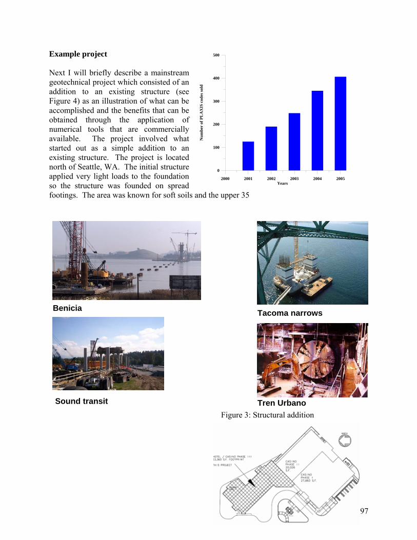
Example project Next I will briefly describe a mainstream geotechnical project which consisted of an addition to an existing structure (see Figure 4) as an illustration of what can be accomplished and the benefits that can be obtained through the application of numerical tools that are commercially available. The project involved what started out as a simple addition to an existing structure. The project is located north of Seattle, WA. The initial structure applied very light loads to the foundation so the structure was founded on spread footings. The area was known for soft soils and the upper 35
2000 2001 2002 2003 2004 2005Years
0
100
200
300
400
500
Num
ber
of P
LA
XIS
cod
es so
ld
Benicia Tacoma narrows
Sound transit Tren Urbano Figure 3: Structural addition
97
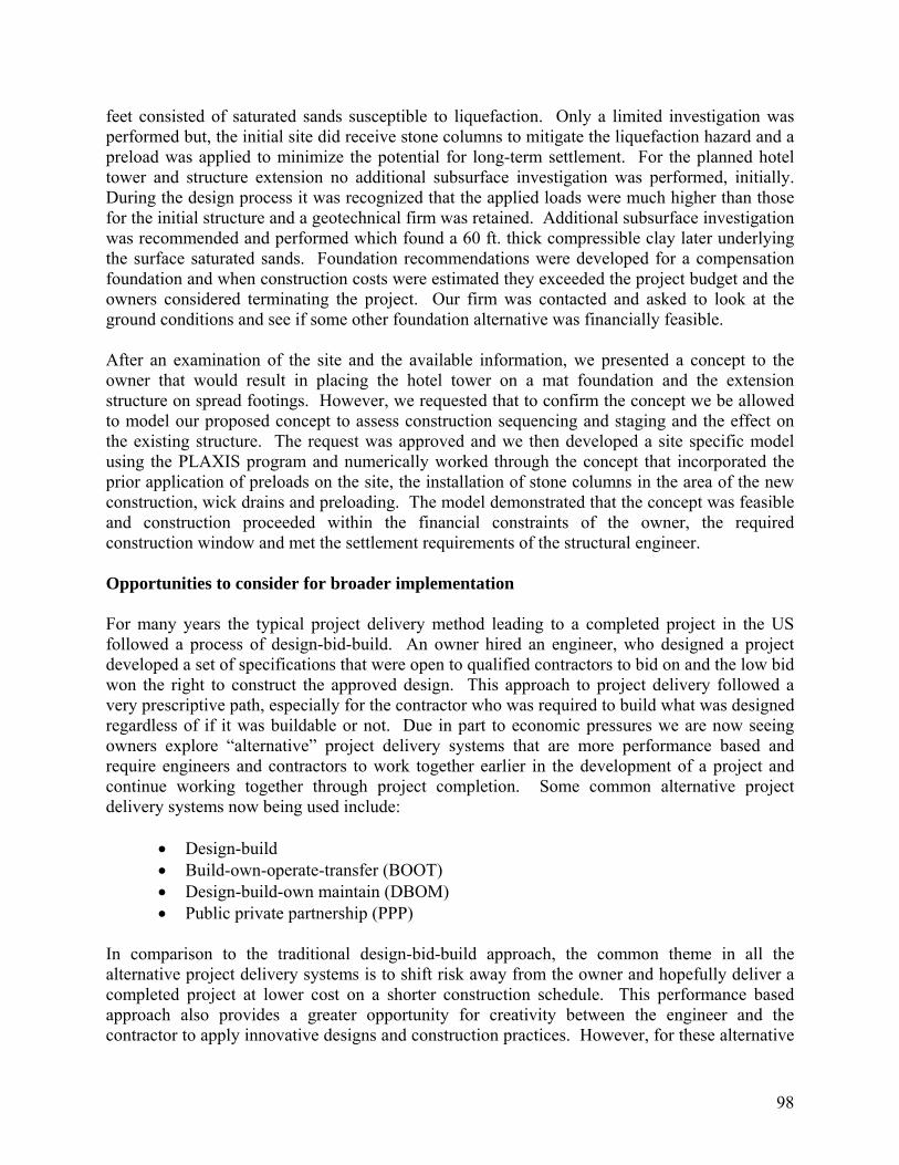
feet consisted of saturated sands susceptible to liquefaction. Only a limited investigation was performed but, the initial site did receive stone columns to mitigate the liquefaction hazard and a preload was applied to minimize the potential for long-term settlement. For the planned hotel tower and structure extension no additional subsurface investigation was performed, initially. During the design process it was recognized that the applied loads were much higher than those for the initial structure and a geotechnical firm was retained. Additional subsurface investigation was recommended and performed which found a 60 ft. thick compressible clay later underlying the surface saturated sands. Foundation recommendations were developed for a compensation foundation and when construction costs were estimated they exceeded the project budget and the owners considered terminating the project. Our firm was contacted and asked to look at the ground conditions and see if some other foundation alternative was financially feasible. After an examination of the site and the available information, we presented a concept to the owner that would result in placing the hotel tower on a mat foundation and the extension structure on spread footings. However, we requested that to confirm the concept we be allowed to model our proposed concept to assess construction sequencing and staging and the effect on the existing structure. The request was approved and we then developed a site specific model using the PLAXIS program and numerically worked through the concept that incorporated the prior application of preloads on the site, the installation of stone columns in the area of the new construction, wick drains and preloading. The model demonstrated that the concept was feasible and construction proceeded within the financial constraints of the owner, the required construction window and met the settlement requirements of the structural engineer. Opportunities to consider for broader implementation For many years the typical project delivery method leading to a completed project in the US followed a process of design-bid-build. An owner hired an engineer, who designed a project developed a set of specifications that were open to qualified contractors to bid on and the low bid won the right to construct the approved design. This approach to project delivery followed a very prescriptive path, especially for the contractor who was required to build what was designed regardless of if it was buildable or not. Due in part to economic pressures we are now seeing owners explore “alternative” project delivery systems that are more performance based and require engineers and contractors to work together earlier in the development of a project and continue working together through project completion. Some common alternative project delivery systems now being used include:
• Design-build • Build-own-operate-transfer (BOOT) • Design-build-own maintain (DBOM) • Public private partnership (PPP)
In comparison to the traditional design-bid-build approach, the common theme in all the alternative project delivery systems is to shift risk away from the owner and hopefully deliver a completed project at lower cost on a shorter construction schedule. This performance based approach also provides a greater opportunity for creativity between the engineer and the contractor to apply innovative designs and construction practices. However, for these alternative
98

project delivery systems to be successful there must be a closer working relationship between engineers and contractors and engineers must have a better working knowledge of construction practices. It is this greater reliance on the understanding of construction practices and the constructibility of a design by the engineer that I suggest represents an opportunity for a broader implementation of numerical approaches into mainstream geotechnical engineering practice. There is also a role that needs to be expanded in the use of integrated numerical modeling with active instrumentation during construction which again, I only believe will be implemented with a greater understanding of both construction activities and numerical methods by geotechnical engineers. However, I would also argue that the weakest link in successfully implementing any of the alternative delivery systems is the engineers understanding of construction means, methods and sequencing. We must remember Terzahgi’s adage that “do not design what you have to wish into the ground.” Therefore, I would suggest that the first action we can implement as a community that will lead to broader implementation of numerical methods, is a greater “hands-on” appreciation of construction practices at the undergraduate and master’s degree level. This can be accomplished directly at universities where NGES sites are located and by university partnerships with contractors in their communities. This idea is not new and can be traced back to remarks made by Dr. Peck in 1973 in his paper entitled, The Direction of Our Profession, where he stated, “construction deserves more attention in design.” My second suggestion that I believe will lead to a broader implementation of numerical methods in practice is a greater emphasis on structural foundation engineering, again at the undergraduate and master’s levels. Over the past 35 years we have allowed our structural brethren to take over design responsibilities that are better suited to be under the preview of the geotechnical engineer. Typically, our reports are now looked to for boring logs, soil classification descriptions, bearing pressures and earth pressure diagrams. I would contend that the geotechnical engineer is better suited to understand soil structure interaction and by working in collaboration with the structural engineering, a better design will result. However, many geotechnical engineers are not comfortable sizing beams and lagging in a solder pile earth retaining system or the sequencing of a tieback system when they graduate. This in my opinion must be corrected. And there is some sense of urgency as we will be faced with the implementation of the LRFD approach in 2007 on all projects receiving federal funding. As I have mentioned previously, the community now has available to it commercial FEM and FD codes for solving a broad range of geotechnical and soil structure interaction problems that incorporates models acceptable for use under many loading and unloading conditions. What is missing from these codes is the incorporation of uncertainty. While the engineer can perform a parametric study, in my opinion it would be a valuable addition to have the ability to assess the influence of material property uncertainty directly as an available input option. However, this also will require greater attention and emphasis placed on material property estimation from laboratory tests and more importantly from in-situ field tests, as well as on the use and proper application of the simpler models such as Mohr-Coulomb and non-linear plasticity models. Again, this needs to occur at the undergraduate and master’s degree levels.
99
As far as the need for the development of new constitutive models and their application, it is my suggestion that the research community look to specific regional areas and local requirements. Let me describe what I mean by example. On a recent trip to China where we met with representatives of the Shanghai Tunnel Engineering Corporation, a contractor for underground works and the manufacturer of tunnel boring machines, they expressed specific concerns on the limitations of currently available models to accurately represent the behavior of their soft clay soils. Specific concerns were construction staging and sequencing in driving tunnels in dense urban environments and the collateral interaction with existing structures and supporting infrastructure. I would argue that similar examples of similar needs exist in our major urban areas with significant planned underground construction for water conveyance and transportation in regions such as New York, Seattle, Indianapolis, Atlanta and other urban centers. I strongly urge the research community to interact with owners, contractors, and the engineering consultant community on this issue. It has always been my belief that the research efforts that make significant contributions are born in the needs of our most practical engineering works. Finally, we should not be passive in reaching out to the current generation of owners and senior engineers. We need to actively promote the positive aspects of the implementation of numerical methods into their firms and projects. Here the objective is not education, but training. Courses such as those sponsored by ASCE and the companies providing the commercial geotechnical software codes need to continue and strive to reach a broader cross-section of the firms practicing mainstream geotechnical engineering. I also encourage the academic community to take advantage of industry sponsored course, such as the pile construction course sponsored by the Pile Contractors Association and the earth retention construction courses sponsored by the ADSC. In addition, case studies should continue to be published not only in the ASCE journals, but also in the trade publications such as those sponsored by the ADSC and the Deep Foundations Institute. In summary I would like to restate that these are the views of one practitioner. What I have attempted to accomplish is to provide some background on the current state of the use of numerical methods in practice and some reasons why I see a gap between research and application into practice at the present time. The example was intended only to demonstrate what can be done on a typical geotechnical engineering project and the benefits that can be obtained through the application of numerical methods that are readily available. Finally, I have tried to offer some suggestions that we as a community might consider implementing to foster the broader use of numerical methods into the mainstream of geotechnical engineering practice and close the gap between research and practice.
100

101
102
Modeling Microcrystaline Wax for Seismic Protection of Art Objects
Debra F. Laefer, Anne Crowley and Pu Jiang, University College Dublin INTRODUCTION Recent work undertaken at the behest of the J. Paul Getty Museum investigated the pro-cedural development for using microcrystalline waxes for the protection of art objects against earthquake-induced movements. The initial stage of this research encompassed the establishment of testing techniques for static tensile and shear tests, cryo-scanning electron microscopy, and density and melting tests. The results of these tests showed a highly complex set of non-linear failure mechanisms both at the wax/object interface and within the body of the wax itself. The second stage of testing will include dynamic material tests and limited shake table experiments, as well as chemical analysis. Because of the nearly infinite range of shapes, sizes, weights, and centers of gravity for art objects, it is anticipated that being able to use finite element method (FEM) modeling will be critical to providing sufficient guidance as to the quantity of wax that needs to be applied for protection of any particular object. The main challenge surrounding this is selection and implementation of an appropriate non-linear constitutive model. The major diffi-culty is in the representation of post-peak capacity at various displacement levels. The accurate portrayal of the post-peak behavior is fundamental to the prediction of behavior during both the initial seismic event and during the multiple aftershocks. BACKGROUND
Protecting art objects from ground movements has long been a concern for art collections located in earthquake-prone regions.1-8 The potential financial losses under such circumstances are significant. A survey following the 1989 Loma Prieta earthquake of 8 museums in the San Francisco Bay Area found 150,000 damaged items corresponding to $10 million in losses. Of that, the Asian Art Museum in San Francisco, alone, suffered $3 million in damage, representing 1% of the total market value of its collection.9 Despite the identified risk, protection solutions have been slow to emerge. A major reason for this is that unlike other vulnerable, high-value, building contents (e.g. computer equipment, hospital equipment, and laboratory items),1 art ob-jects are almost by definition unique. Thus, a single collection may be comprised of tens of thou-sands of objects of varying sizes, weights, geometries and materials. Consequently, pioneering a widely applicable intervention method has been difficult. One popular method is the application of wax to the bottom of ceramic and glass objects.1-3,5 The approach is attractive, because the wax is inexpensive, theoretically reversible, and does not impede the visitor’s view (Fig.1). Micro-crystalline waxes, like paraffin waxes are by-products of petroleum processing. The crystal struc-ture of the microcrystalline waxes is needle-like and smaller than that of paraffin, which has a plate-like crystal structure. The microcrystalline waxes also contain higher proportions of iso- and cyclo-alkanes than paraffin waxes, which causes the microcrystalline waxes to be more malleable and adherent than the paraffin ones.10 Despite the documented success of microcrystalline wax against seismic activity,1 there are risks associated with its application. The high porosity of some ceramics and the composition of some glazes and paints make certain ceramics vulnerable to sur-face damage from the wax.5 As a direct reflection of the multitude of ceramic materials and fin-ishes involved, prediction of such vulnerability to wax-generated damage is not easily assessed. Consequently, there needs to be a conservative approach in the application of the wax – minimiz-ing the quantity applied to match the calculated, anticipated need. To date there is no independent

103
or manufacturer-provided guidance as to the most effective method of wax application or the re-quired quantity of wax needed to resist a specified amount of tensile and/or shear force. The methods described in this paper were essential for an initial determination of such guidance.
Fig. 1. Application of Microcrystalline Wax for Seismic Protection EXPERIMENTAL RESULTS In addition to establishing the fundamental mechanical properties of the materials in ten-sion and shear, an understanding was needed as to whether the failure was occurring within the wax’s mass or at the surface of the wax/object or wax/display case interface. The question gains particular importance because of the tendency to use the wax in combination with a pre-application of a thermoplastic acrylic resin as a protective coating. The resin has the dual func-tion of acting as a consolidant and as an adhesive. Under some limited testing conditions, the resin has been shown to prevent both wax-generated staining and fragment removal.5 The pre-ferred product is Paraloid B-72, a methylacrylate copolymer.12 As such, determination of the failure mechanism and the location of the failure were sought, as well as the failure capacity of the wax applied both with and without the coating. To develop good practice guidelines for the application of microcrystalline waxes for the protection of art objects from ground movements, a series of 70 tensile and 175 shear tests were conducted. Six waxes were studied. Beeswax and paraffin were considered, in addition to four microcrystalline waxes: Multiwax, Secure WaxTM, Quake HoldTM, and Earthquake wax. The first three of the microcrystalline waxes were com-mercial products obtainable in the United States.13-15 The fourth was provided by the J. Paul Getty Museum as a product being used in Dolmabahce Place in Istanbul, Turkey. The non-microcrystalline waxes were included as points of comparison to enhance the understanding of the importance of specific industrial processing and chemical composition on wax behavior. Three tensile failure modes were observed: adhesion (Fig. 2a), mixed (Fig. 2b), and co-hesion (Fig. 2c). The microcrystalline waxes experienced cohesion or mixed failures, while the beeswax and paraffin wax exhibited brittle, adhesion failures. The microcrystalline waxes tested using the melted preparation procedure without a resin coating exhibited a wide performance range – ranging from an average low of 37.67 kN/m2 (Secure WaxTM) to an average high of 167.33 kN/ m2 (Multiwax) [a 344% difference]. The microcrystalline waxes exhibited residual strength in the post-peak loading (fig. 3).
Lead steel balls inserted to lower centre of gravity
Ceramic art object
Wax
Pedestal

104
2a Adhesion 2b Mixed 2c Cohesion Fig. 2. Tensile Failure Modes
Fig. 3. Tensile-loading Displacement
A total of 175 shear tests were performed. The shear tests showed similar results to the tensile ones. Despite the ability to withstand 400% more inherent shear stress than the microcrys-talline waxes, beeswax and paraffin regularly exhibited the same brittle failure mechanism as demonstrated under tensile loading (Fig. 4). The shear displacement curves were similar to those in the tensile tests in terms of non-linear residual shear capacity.
Fig. 4. Failure modes in inherent shear tests
Brittle failure
Ductile failure
-200
-100
0
100
200
300
400
500
600
0 0.5 1 1.5 2 2.5 3 3.5 4 4.5 5
Load (N)
Microcrystalline wax no coating Microcrystalline wax with coating Beeswax no coating Beeswax with coating
Crosshead position (mm)
Load
(N)
105
CONCLUSION Laboratory tests to date strongly emphasize the need for a non-linear constitutive model to im-plement FEM modeling. The exact details will depend upon a further laboratory testing to clarify the role of confinement stress and how these relationships change with the use of a resin coating. A difficulty that remains is that because of the relatively niche usage of microcrystalline waxes, models non-linear constitutive models constructed to date rely upon a series of established mate-rial behaviors or a range of parametric inputs, which are simply not available or applicable for wax. REFERENCES [1] Benuska, Lee (Ed) “Architecture, Building Contents and Building Systems,” Earthquake
Spectra, Supplement to Volume 6, Earthquake Eng. Research Inst., May, 1990, pp. 339-376. [2] Cornu, E. and Bone L., “Seismic Disaster Planning: Preventive Measures Make a Differ-
ence,” Western Assoc. for Art Conservation Newsletter, Sep.1991, Vol. 13, No. 3, pp. 13-19. [3] Ginell, W., “Seismic Damage Mitigation Techniques for Objects,” The Getty Conservation
Institute Newsletter, URL: http://www.getty.edu/conservation/publications/newsletters/10_3/ feature1_12.html, 1995, Vol. 10.3, 13 Feb. 2005.
[4] Harold, J. M., “Disaster Mitigation for the Bertrand Collection Artifacts,” Cultural Resource Management, URL: http://crm.cr.nps.gov/, 1995,Vol. 18, No. 6, pp. 15–17.
[5] Hascall, J. (2001), “Studio Earthquake Preparedness Tip Sheet,” Artists’ Quake Aid Final Report, Section X. http://www.artisttrust.org/accomps/aquareport/sectionX.html.
[6] Lever, Y. “Thinking Ahead: Disaster Planning for Museums,” CultureWork,URL: http://aad.uoregon.edu/culturework, April 2000, Vol. 4, No. 2. n.p.
[7] Podany, J.C., “The Protection of Cultural Heritage in Museum Collections From Earthquake Damage,” Symp. Conservation and Preservation of Cultural Artifacts, Taipei, Taiwan, 1995.
[8] Podany, J.C., “Developing and Practicing an Emergency and Disaster Response Plan,” In-ternational Symposium Risk Preparedness for Cultural Properties Development of Guide-lines for Emergency Response, Kobe/Tokyo, Japan, 1997, pp. 347-359.
[9] Federal Emergency Management Agency (FEMA), “Reducing the Risks of Non-Structural Earthquake Damage: A Practical Guide,” 1994, p. 9.
[10] Mansoori A. et al, Fuels and Lubricants Handbook: ASTM Manual Series: MNL37WCD, “Chapter 19 Petroleum Waxes,” 2003, pp. 525-531, ASTM Int’l, West Conshohocken, PA.
[11] Acryloid B-72, Adhesives and Consolidants, 2000, URL: http://nautarch.tamu.edu/class/ anth605/File2.htm, Conservation Research Laboratory, College Station, Texas, 17 Feb. 2005.
[12] Podany, J., Garland, K.M., Freeman, W.R., & Rogers, J., “Paraloid B-72 as a Structural Ad-hesive and as a Barrier within Structural Adhesive Bonds: Evaluations of Strength and Re-versibility,” J. American Inst. for Conservation, 2001, Vol. 40, No. 1, pp. 15-37.
[13] Adhesives and Consolidants and Archival Storage and Display, URL: http://www.silcom.com/~css/, Conservation Support Systems, 17 Nov. 2004.
[14] Quake Hold Products, Waxes, Conservation Tools, Equipment & Supplies, URL: http://www.conservationresources.com/Main/section_39/section39_07.htm, Conservation Resources International, Springfield, Virginia, 20 Nov. 2004.