abstract - uh cullen college of engineering coursescourses.egr.uh.edu/ece/ece4335/ece 4335 f2014...
TRANSCRIPT

December 9, 2014
Andrew TuckerAggieSat Lab - Aerospace Engineering DepartmentTAMU 3141611C H.R. Bright BuildingTexas A&M UniversityCollege Station, TX 77843-3141
Dear Mr. Tucker,
CoogCrew is writing to formally relay and elaborate on the status and success of the University of Houston AggieSat4 collaboration with the AggieSat Lab in regards to the development of the AggieSat4 (AGS4) satellite.
From the attached document, it is CoogCrew’s hope that it is apparent that the team has accomplished the agreed upon semester goal of developing the Visual Data Capture System (VDCS) and Ground Support Communication (GSC) subsystems of the AGS4 satellite.
Please review the supporting content associated with the on schedule completion of CoogCrew’s Fall 2014 goal.
If you have any questions, please contact our team leader, James Annis, by email at [email protected] or by phone at 713-591-1638.
Sincerely,
James AnnisBrian McNeilTori Speer-MansonSean Strickland

University of HoustonAggieSat4 CollaborationFinal Technical Report
AGS4 - CoogCrew Members:
Emery Annis
Brian McNeil
Tori Speer-Manson
Sean Strickland
Due: December 9, 2014
Project Sponsors:
AggieSat Lab (Texas A&M)
Dr. Robert Provence (NASA)

AbstractThe University of Houston AggieSat collaboration team, CoogCrew, developed two
subsystems over the semester for the AggieSat Lab’s Low earth Orbiting Navigation Experiment
for Spacecraft Testing Autonomous Rendezvous (LoneStar) campaign. This program is intended
to research novel low cost autonomous rendezvous and docking for small satellites. The two
subsystems developed were the Visual Data Capture System (VDCS), software developed to
support the camera in this mission, and Ground Support Communications (GSC), software to
interact with the satellite’s flight computer while it is on the ground. It was necessary for the
flight computer to be replicated in this project to confirm that the developed subsystems would
work with the satellite. The flight computer was constructed and successfully certified as a
replica to the AggieSat4 (AGS4) flight computer. The flight computer would run an exact copy
of the AGS4 code including the Command Data Handling (CDH) subsystem, the state machine
process that directs data and programs access to satellite hardware. Both developed subsystems
were integrated with the flight computer and camera hardware and operated as expected. These
subsystems complete the deliverable portion of our project for this semester.

Background and GoalThis document describes the University of Houston, AggieSat “CoogCrew” team’s
collaboration with Texas A&M AggieSat Lab (AGSL) in the development of AggieSat4 (AGS4)
satellite subsystems Visual Data Capture System (VDCS) and Ground Support Communication
(GSC).
The AGS4 satellite is being developed by AGSL and will launch in Spring 2015 aboard a
SpaceX Dragon capsule. AGS4 is part of the Low earth Orbiting Navigation Experiment for
Spacecraft Testing Autonomous Rendezvous and Docking (LoneStar) [1] campaign’s 2nd
mission designed to research autonomous rendezvous and docking of small spacecraft in low
earth orbit. Research will be accomplished by releasing and tracking Bevo-2, which is a cube
satellite developed by University of Texas at Austin.
The primary purpose of VDCS as outlined in the AGS4 Mission Operational Timeline
[2], will be to capture images before, during, and after AGS4 release of Bevo-2. The GSC
subsystem is designed to aid in the command and diagnostic of AGS4 during all pre-flight
testing on earth via a user terminal connected externally to the satellite. All systems aboard the
satellite are due to be delivered to AGSL by December 31, 2014. The development of the VDCS
and GSC subsystems represent the target objective for the UH CoogCrew’s first semester of
work. For the final semester, the UH CoogCrew will remain on call to support the testing and
final development of the AGS4 satellite due to be delivered to NASA on February 22, 2015. The
UH CoogCrew will also finalize and test the integration of all satellite modules to ensure all
modes have been developed and ordered sequentially to complete each mission sequence.
1

The remainder of this document will outline the significance of the project and include an
analysis of the projects need and user requirements. It will also include a technical description of
the developed subsystems and details pertaining to the final product. Finally, the overall budget
and discussion for next semester goals will be discussed.
Problem, Need, and SignificanceAerospace engineering has a need for low cost autonomous rendezvous systems, hence
the LoneStar program. In order to test these developing systems two space-borne objects in close
proximity need to be able to track one another’s position. In prior AggieSat projects, AggieSat2
in particular, the two satellites did not separate after their deployment. This mission was
considered a failure as Bevo-1 and AggieSat2 were unable to separate, establish a
communication link, and share relative GPS navigation data.
This failure of satellite separation was taken into consideration for the next AggieSat
mission and it was concluded that a Visual Data Capture system would be implemented to
provide visual data of the separation. This would capture the release event of the two satellites,
and would allow the team to tell if and when a problem occurred during separation. Additionally,
this camera system would be able to provide visual feedback of their separation to validate the
effectiveness of the tracking system. This is a high priority on the AGS4 mission, any failure of
the VDCS would be considered a failure for the entire project. The VDCS subsystem would will
be required to capture images before the release event, during the release event and after.
Furthermore, this subsystem is to be self-monitoring, checking whether the camera is capable of
taking images given its temperature or memory status.
2

Once the satellite is built and sealed it must be able to complete a Day in the Life (DITL)
testing sequence performing all operations it would in space for validation. Only until this point
would the satellite be able to run an entire mission script that has been pre-programmed to
memory and respond to limited commands over wireless communications. During pre-flight
testing of the AggiSat4 satellite there are no subsystems available in place to aid diagnostic
checking of the satellite as well as providingor to provide commands to the flight computer.
A new subsystem called Ground Support Communications would be required to aid in
this process as a diagnostic tool. The GSC subsystem would need to be able to execute command
modes and upload new code or data to the satellite’s flight computer while on the ground
allowing the ground crew to check the satellite’s status and interact with it during testing.
The AggieSat Lab requires these subsystems to be completed by December 31, 2014 in
time for pre-flight testing to begin at the NASA Johnson Space Center on February 22, 2014. In
order to validate all systems, the satellite must be fully operational with the VDCS subsystem
ready for flight and the GSC subsystem ready for the pre-flight testing.
Completing development of these subsystems is the goal for the end of this semester.
This leads into the goal for next semester, which is to provide support to the AGSL’s ground
crew by aiding with any of the testing procedures and the usage of the developed subsystems.
User AnalysisThe AGS4 satellite will be entirely controlled by the AGSL ground support team located
in Texas A&M, which includes a group of aerospace engineering graduates and undergraduates
as well as other engineering discipline majors. Dr. Helen Reed, who is the Principle Investigator
3
for AGSL and supported by many at NASA, leads the group. Communications and data
transmissions will be provided by TAMU’s Riverside radio station.
The user that implements these developed CoogCrew subsystems will be an operator
from the AGSL. The operator will have in depth knowledge to the AggieSat4 program, have
detailed understanding of the developed subsystems as well as generally experienced in
aerospace engineering. The developed subsystems will have been documented in detail so that
any aerospace engineer who builds the mission scripts may implement these systems by
following specified guidelines.
Engineers from AGSL and NASA will operate the GSC subsystem during the pre-flight
testing sequence. The VDCS subsystem will operate more autonomously by switching between
pre-established mission modes as commanded by ground support from AGSL.
Overview DiagramCoogCrew’s goal for this semester was to develop the Visual Data Capture and Ground
Support Communication subsystems for the AggieSat4 satellite. Completed deliverables of this
goal will be submitted to AGSL by December 31, 2014.
The team’s goal for next semester is to be available to AGSL for maintenance and
debugging purposes in regards to VDCS and GSC. CoogCrew will also be affiliated with the
testing process involving the two subsystems, which will be implemented at the NASA Johnson
Space Center in February.
Figure 1 provides an overview diagram of how the VDCS and GSC subsystems will
interact with the AGS4 satellite as of the Fall 2014 semester.
4

Figure 1 - University of Houston, CoogCrew developed AggieSat4 subsystems include the Visual Data Capture System (VDCS) and the Ground Support Communications (GSC).
The Aerospace Corporation 2 mega pixel camera associated with the VDCS will be
located on the side of the AGS4 satellite right above where Bevo-2 will be released from the bay
as depicted by the diagram above. Essentially the following event should occur for the image
capturing process. The AGS4 satellite will rotate to where the back of the satellite (the side that
the camera is not on) is facing toward the sun so that light will potentially be shining toward the
cube satellite during the release event ensuring a viewable captured image. Once this occurs,
Bevo-2 can then be released. Anticipating that the release event will occur rapidly, to guarantee a
captured image, the camera will instantly and continuously be capturing images during the event
using Bevo imaging mode, which utilizes the rapid-fire camera function.
GSC is comprised ofcomprises a Linux-based user-terminal communicating serially via
an RS-232 to the Technologic Systems, TS-7800 flight computer. This subsystem will aid AGSL
with pre-flight testing utilizing user-terminal associated menu functions. GSC will also serve as a
5

communicative tool for mission control to check the status of the satellite and its various
subsystems and to easily change the mode of operation of the satellite.
The Command and Data Handling state machine is capable of communicating with all
subsystems associated with the ASG4 satellite. CDH serves as a manager of the satellite
executing pre-developed event sequences or commands transmitted via GSC from mission
control.
Engineering Specifications and ConstraintsThe project will be in a space environment dictating the robustness and cost of the
hardware. The hardware must be vigorous enough to handle space transportation and light
enough to reduce expenses. The hardware must be able to withstand the temperatures of space as
well as working isolated with limited communications and power. The software should be
protected from single event upsets and be reliable to recover should one occur. All of the
hardware and software associated with the AGS4 satellite must comply with NASA and AGSL
regulations. See the constraints associated with the overall project in Table 1.
Table 1 – AGS4 Constraints
6

VDCS Specifications
For the VDCS subsystem, the camera hardware must be able to capture images varying in
resolution and compression ratios. Additionally, in terms of function, the camera must be able to
rapidly take pictures to track the position of the deployed small satellite. Table 2 illustrates the
specifications for the VDCS subsystem.
Table 2 – VDCS Subsystem Camera Specifications.
The software controlling the camera must be able to perform a reset should the system
fail. The VDCS subsystem must also be able to download image information, thumbnails, and
7
pictures. Checking and resetting memory also should be performed by the VDCS software as
well as monitoring the cameras temperature when the camera is powered on.
GSC Specifications
The GSC user-terminal developed by the team is intended for testing and interfacing with
the satellite’s flight computer and hardware as a black box on the ground. This capability enables
the ground crew to interact with the satellite on the ground to ensure its normal operation after
the rigors of pre-launch testing. This subsystem must be able to serially communicate between a
PC based terminal and the flight computer. From the terminal, the ground support crew must be
able to issue all commands as defined in the GSC specifications seen in Table 3.
Table 3– GSC Subsystem Specifications
The GSC subsystem is utilized for user-AGS4 communication. The specified
communication method is through an RS-232 serial path. This subsystem must be able to
connect and disconnect to the satellite to send commands, perform functions and change between
various modes associated with the satellite. Furthermore, GSC should be capable of launching
8

event sequences, transmitting files and performing Linux BASH commands directly to the flight
computer as well as the capability to completely shut down all subsystems.
Target Objective and Goal AnalysisCoogCrew’s target objective of demonstrating the VDCS subsystem integrated with
CDH, and as commanded by GSC, has been successful and is on schedule for completion by
December 31, 2014. Objectives completed leading up to the target objective can be seen in
Figure 2, the most up to date goal analysis for this semester.
Figure 2- Goal Analysis and Target Objective for University of Houston CoogCrew first semester.
Capture and Process Camera Images (via Linux Pc)
The starting objective related to the VDCS camera development was to capture and
process camera images on a Linux PC. This objective included developing a menu based
software program where a user can command the camera hardware to capture images within
9

AGS4 -VDCS specification (Table 2). The images captured had to be able to be downloaded,
processed, and displayed in any typical image viewing application.
Before developing software to communicate to the camera, the camera command set
manifest provided by the manufacturer was verified and updated. The manifest is a document
containing every byte stream command argument that could be transmitted to the camera along
with the expected camera responses per transmission. For verification, each commanding
argument was tested using RealTerm software, which allows for anticipated byte sequences to be
sent and received over an RS-232 serial port. After successfully capturing and receiving image
data, very few discrepancies were identified and documented throughout the testing process.
The software development began with programming library functions (or drivers) to
bridge the gap between software and hardware. Several library functions sets had to be
developed in order to achieve the capabilities stated within the specifications. The developed
functions would also serve as a starting foundation for all future branch objectives. Simpler
function sets would send two or three command bytes to the camera and wait for an
acknowledgement response to confirm successful execution of the function. More complex
functions, such as downloading standard images, rapid-fire images, and thumbnails all required
post JPEG file processing because the raw data received directly from the camera was an
incomplete file and un-viewable. These functions required the pre-pending of a JPEG header
section, which contains data specific to the image resolution and compression ratio as well as the
encoding scheme.
A user interface menu program was developed for a user to execute any of the developed
function sets. The main menu functions are shown below in Figure 3.
10

Figure 3 - User interface menu program developed for camera control.
All of the software was developed using C++ in a Linux environment configured to
replicate the Linux environment of the AGS4 flight computer.
Once the software was developed, it was debugged and verified that each library function
could accomplish its purpose to within VDCS specifications (Table 2). For example, images of
all valid resolutions and compression ratios were captured, downloaded, and processed by the
library functions and viewable by any common image viewing application. All generated data
indicated the proper operation of the software’s ability to control and receive data from the
camera. The software was documented, submitted, and demonstrated to AGSL.
Capture and Process Camera Images (via Flight Computer)
The next objective, to capture and process images via the flight computer, was simply a
migration of the camera’s menu based program operating on a Linux PC over to the TS-7800
flight computer. This would required the completion of objectives specific to the configuration
of the flight computer to AGSL standards (discussed later). In order to satisfy objective
requirements, all of the previously developed software library functions must operate on the TS-
7800 and meet VDCS specifications (Table 2). If the software didn’t perform correctly then
corrections would have been made. Because the C++ encoding environment was setup to
11

emulate the TS-7800’s Linux environment, all library functions migrated without error. Tests
were conducted on an AGSL spare flight computer, and confirmed to properly achieve all
camera functionality to with the specifications.
Replicate a Certified AGS4 Flight Computer
The flight computer was to be replicated in order to verify that the subsystems would
perform appropriately with the actual AGS4 mission. The replica flight computer is the
Technologic Systems TS-7800 containing the ARM9 processor, which is commonly used for
small satellite operations. Code for this board is open source and has been used for quite some
timeverified by other users (?). This processor allows expandable memory such as the SD and
micro SD ports that the operating system would be stored on. This processor has PC-104 bus
structure expandability allowing for multiple expansion TS-SER4 boards with serial ports to be
added. This expandability allows for a multitude of satellite hardware to be interfaced with this
flight computer. The hardware and software loaded to the satellite must meet AGSL
specifications. These specifications include installing jumpers to configure each boards COM
port and IRQ settings as well as installing the Linux operating system.
12

In order to certify the replica AGS4 flight computer in accordance with AGSL
specifications, checklists outlined in the documents referenced in Table 4 were completed and
submitted to AGSL.
Table 4 - AggieSat 4 Flight Computer Installation Checking and CDH Software Design documentation.AGS4-02-04-005-R2 CDH
Computer Hardware Assembly
Checklist for hardware installation includes board number
identification and all jumper configuration
AGS4-02-01-003-R0 CDH
Flight OS Description
Description of each OS Boot Script available and
instructions for how to switch between each
AGS4-02-04-006-R0 CDH
Flight Operating System
Installation Procedure
Checklist for Operating System installation procedure
includes loading of Linux operating system and partitions
Execute CDH Process on a Certified AGS4 Flight Computer
The next milestone was to execute the flight computer’s master process, Command and
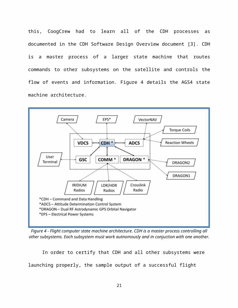
Data Handling (CDH). In order to do this, CoogCrew had to learn all of the CDH processes as
documented in the CDH Software Design Overview document [3]. CDH is a master process of a
larger state machine that routes commands to other subsystems on the satellite and controls the
flow of events and information. Figure 4 details the AGS4 state machine architecture.
13

Figure 4 - Flight computer state machine architecture. CDH is a master process controlling all other subsystems. Each subsystem must work autnomously and in conjuction with one another.
In order to certify that CDH and all other subsystems were launching properly, the
sample output of a successful flight computer boot and initiation of master_script, which starts
each of the subsystems, is included in Appendix A.
Demonstrate Control of VDCS Subsystem via CDH
The final objective pertaining to the camera subsystem was for the development of a
VDCS subsystem, which would interface between CDH and the developed camera library
functions. To meet this objective a higher level of software, the VDCS subsystem, was
developed in C++ to receive commands from CDH and execute them accordingly while also
maintaining the camera hardware. The VDCS subsystem is designed to execute a specific
sequence of camera related events in order to accomplish a greater task such as capturing the
14

release of Bevo-2. VDCS commands the camera indirectly by calling the camera library
functions. The functions were further improved to include return arguments in order for the
VDCS subsystem to determine if the function executed properly or not. This is currently only
used for error reporting, but in the future will likely be expanded to include recovery cases
should an error occur. For example, if communication is lost with the camera, VDCS should
attempt to reset the camera, and possibly even cycle power to the camera and resume its intended
mode of operation immediately.
The VDCS subsystem can be placed into a single “mode” at any time by CDH. A full list
of the modes can be seen below in Table 5.
Table 5. Listing of VDCS subsystem modes.System Checkout Verifies proper operation of camera hardwareIdle Subsystem is active with camera hardware offPrepare Camera Power on and Initialize camera for usageBevo-2 Imaging Captures specific image types of Bevo-2's releaseEarth Imaging Captures specific image types of EarthGeneral Imaging Captures images for an unspecified eventGet Image Info Obtains data about images stored in memoryDownload Downloads all JPEG data (including thumbnails)Erase Memory Erases cameras memoryTemp Reset Resets a temperature alarm conditionShutdown Stops VDCS subsystem process
Each of the listed modes performs a sequence of camera hardware events in order to achieve the
mode’s objective while also simultaneously monitoring the camera’s temperature and updating
the IPC watchdog (ensures VDCS subsystem is still active). For example, the system checkout
mode will be executed sometime shortly after AGS4 powers on for the first time. This mode
executes many camera functions and will generate a small data log file easily transmittable to
earth through the low data rate radios (low bandwidth communication) for a flight controller to
15

review. This data file contains key information to deem the VDCS subsystem mission ready or
alternatively provides information relative to a problem for further review and potential
troubleshooting. An example of the log file is in Appendix B. Each mode will actually log in a
similar fashion while the overall VDCS process is logged in detail into a larger data file should
problems arise requiring more data. The generated log files (Appendix B) provide useful data,
which helped easily certify that the objective was met. Each mode that was developed was
verified that it achieved its designed objective and produced data conforming to the VDCS
specifications (Table 2).
At this time, the exact specifics of each mode are being discussed with AGSL, but tests
indicate that VDCS is properly executing CDH commands to accomplish the specific mode
function. Using an event sequence file (processed by CDH), VDCS specific events were
sequenced by CDH to command VDCS to execute each mode listed in Table 5. To ensure the
proper operation of each mode, all generated data was reviewed for proper execution. The data
includes JPEG files, image information files, mode specific data logs, and the detailed VDCS
master subsystem data log file.
Establish Serial Communication between GSC User Terminal and CDH
In order to meet the requirements specifications for GSC as established in Table 3, RS-
232 serial communication was established between a C++ developed user terminal and the AGS4
satellite. Due to the criticality of transmission and the fact that the data segment of transmission
including file names and content could be of unknown length, a packet delivery system was
established. Each packet included the header, which was comprised of the sender ID, noting
whether the packet is from the GSC terminal or the AGS4 satellite, and the command ID, which
denotes the actual command function that the satellite is to perform. Additionally, the
16

undetermined data length must be terminated with a string “T3RM|N” to identify this is the end
of the sent packet. An illustration of the GSC Data and Command Packet can be seen in Figure 5.
Figure 5 – GSC Data and Command Packet illustrating the Header containing the sender ID and command ID, the data segment, and the termination string trailer.
Send and receive packet functions were established on both the user terminal and the
AGS4 satellite to append/prepend the header and trailer segments upon transmission and strip
them upon receiving before being passed to the command handler on each system. The serial
communications were tested and validated by testing send_ACK, send_NACK, and send_COMP
functions between AGS4 and the user terminal.
Operate AGS4 via GSC User Terminal
In order to implement the more advanced functions specified for GSC in Table 3, a menu
program was developed in C++ to run in Linux to command the AGS4 satellite. The menu
program is illustrated in Figure 6.
Figure 6 - Ground Support Communications (GSC) user terminal supported functions.
17

The first function implemented was the ability for the user terminal to connect and
disconnect from the satellite successfully without interfering with its function. This allows the
engineer to connect and disconnect from the satellite throughout the testing sequence, which
could last for days or weeks. The terminal must also be able to change subsystem modes., Ffor
example, it must be able to change from the VDCS subsystem, Bevo Release Capture Mode to
the COMMS subsystem, Bevo-AGS4 Radio Uplink. Next, the GSC terminal must be able to
launch event sequences, which could include many mode changes between various subsystems.
The event sequence script files were assumed to already exist in the mission scripts directory on
AGS4 and GSC would simply launch those scripts into CDH. The GSC terminal must also be
able to power on or off satellite hardware such as the VDCS camera or Communications Link
Radio.
The next command implemented was the ability to transmit files to and from the
satellite. These files include data such as pictures, log files, mission scripts, as well as new code
or functions to be uploaded to the satellite. The next function was to be able to send Linux
BASH commands. The commands would be received by CDH and passed to Linux to be
executed. The output would then be captured and returned back to the user terminal. Finally, the
GSC terminal must be able to issue system shut down commands allowing the satellite to be
gracefully shutdown in preparation for flight. Each of these functions were implemented with
multiple handshake sequences to ensure each command was successfully received over the serial
communications and executed without error.
Target Objective: Demonstrate VDCS and GSC Subsystem Integration with CDH
CoogCrew demonstrated all of these subsystems operating on the flight computer by
launching a VDCS event sequence through the command data handler as issued as a command
18

from the Ground Support Communication subsystem. A sequence to simulate the Bevo satellite
release and capture photos is illustrated in Figure 7 and includes the camera being commanded to
take 10 rapid-fire images, 2 images at high resolution, and then download all of these images and
thumbnails. During this mode the camera is also continuously monitored for successful operation
and valid operating temperature range.
Figure 7 - Ground Support Communications (GSC) user terminal supported functions.
The ground support user terminal was then utilized to download the various images
captured and log files generated. The GSC code and documentation has currently been delivered
to AggieSat Lab and is currently being used to test and validate other systems in preparation for
delivery to NASA.
19

BudgetA budget was created for this semester to ensure time and money was spent effectively.
Test plan cost, weekly team meetings, facilitator/advisor cost, miscellaneous hardware, and
travel time to Texas A&M’s AGSL for the semester were essential to record as expenses. Table
6 illustrates total expenditures spent for this semester.
Table 6 - Total expenditures (ECE 4335)
The total cost for the test plan included research and manual labor applied to complete all
objectives leading up to the target objective. Weekly meetings included class time, team
meetings, and AGSL videoconferences that were attended throughout the semester. Facilitators
and advisors were paid for class time and guidance provided to us. For subsystem related
hardware, AGSL provided the Technologic Systems TS-7800 flight computer and the Aerospace
Corporation 2 Mega Pixel camera. These expenses were not included within the budget,
however, miscellaneous hardware was purchased, which included RS-232 cables and equipment
20

associated with building the flight computer. In regards to travel time for the semester, AGSL
was visited once so far and another visit to deliver all developed systems has been scheduled for
the near future.
An anticipated budget has been created to prepare for next semester, ECE 4336, which
can be seen in Table 7.
Table 7 - Anticipated Expenditures (ECE 4336)
Much like the budget for this semester, the anticipated budget for next semester includes
future test plan cost, weekly team meetings, facilitator/advisor consultation, hardware, and travel
time. The amount of manual labor predicted to be applied to the future test plan is much less than
this semester due to the fact that VDCS and GSC will have already been completed and
delivered to AGSL by the December 31, 2014 deadline for testing and approval. Once AGSL has
completed the testing process, it is possible that errors and/or system malfunctions could arise,
which is where the CoogCrew will be needed for repairing purposes. Not only will the team be
21

responsible for debugging the two subsystems, documentation and testing procedures will also
need to be written. The weekly and facilitator/advisor meeting costs are anticipated to be very
similar to this semester; therefore, there has been no change to the total cost of those two budget
categories. At this time, the team does not foresee needing any additional hardware, however,
this could change between now and then. In regards to travel time, it is expected that at least one,
if not two trips will be made to Johnson Space Center in order to observe and assist with the
testing procedures performed on the VDCS and GSC subsystems.
ConclusionIn conclusion, the University of Houston AggieSat Lab collaboration CoogCrew was able
to successfully develop two subsystems of the AggieSat4 satellite, the Visual Data Capture
System (VDCS) and Ground Support Communication (GSC), according to NASA and AggieSat
Lab requirements. By December 31, 2014, all code and documentation will have been submitted
to the AggieSat Lab for testing and approval. As for next semester, CoogCrew is ready to
perform maintenance on the two modules where repair is needed. With AggieSat4 being
launched in Spring 2015, it is CoogCrew’s hope that the VDCS and GSC will aid in the success
of LoneStar’s 2nd mission designed to research autonomous rendezvous and docking of small
spacecraft in low earth orbit.
22
References[1] “National Aeronautics and Space Administration,” 29 July 2014. [Online]. Available:
http://www.nasa.gov/mission_pages/station/research/experiments/859.html. [Accessed 26
November 2014].
[2] H. Hasan, “Mission Operational Timeline – AGS4-09-02-001-R0,” AggieSat Lab, College
Station, 2012.
[3] Robert Singletary, “CDH Software Design Overview – AGS4-02-01-001-R0,” AggieSat
Lab, College Station, 2012.
23

Appendix A: Sample Output of Successful
Flight Computer BootIn order to verify the successful launch of AGS4 flight software including CDH and other subsystems, the sample output below was provided.
>> TS-BOOTROM – built May 11 2011>> Copyright (c) 2008, Technologic Systems>> Booting from microSD card…Uncompressing Linux… done, booting the kernel.Setting Up TS7800 * Installing TS7800 Drivers * Mounting Filesystems * Mounting Debian PartitionChecking for USB Update * Installing Drivers * Checking for USB DeviceInstalling Serial Ports From TS-SER4s (x3) * Installing Board B * Installing Board C * Installing Board DInstalling USB Ports for LDR Radios * Installing USB Serial Drivers * Setting up Serial PortsMounting SD Card * Creating /agsl Folder * Mounting SD Card to /agslRunning 0scriptClearing Environment of: ./14.30.01Environment ClearedVersion: ./14.30.01Running master_scriptMaster Script starting on …Clearing FIFOs FolderClearing Log FolderCompiling Processes* Compiling Libraries* Compiling CDH* Compiling ACS* Compiling ADS* Compiling COMM* Compiling HDR* Compiling VDCSSetting PermissionsRunning Processes* Running CDH
Beginning Setup Sequence * Starting ACS IPCIPC acs: Server Creating FIFOsIPC acs: Server Opening STX FIFOs* Running ACS
24

IPC acs: Server Opening SRX FIFOsIPC acs: Server Setup Completeacs: Side: 0 STX: 3 SRX: 4 CTX: 6 CRX: 5acs: Filenames: ‘/agsl/0fifos/acsst’, ‘/agsl/0fifos/acssr’, ‘/agsl/0fifos/acsct’, ‘/agsl/0fifos/acscr’ * Starting VDCS IPCIPC vdcs: Server Creating FIFOsIPC vdcs: Server Opening STX FIFOs* Running ADS* Running VDCSIPC vdcs: Server Opening SRX FIFOsIPC vdcs: Server Setup Completevdcs: Side: 0 STX: 7 SRX: 8 CTX: 10 CRX: 9vdcs: Filenames: ‘/agsl/0fifos/vdcsst’, ‘/agsl/0fifos/vdcssr’, ‘/agsl/0fifos/vdcsct’, ‘/agsl/0fifos/vdcscr’ * Starting COMM IPCIPC comm: Server Creating FIFOsIPC comm: Server Opening STX FIFOs* Running COMMIPC comm: Server Opening SRX FIFOsIPC comm: Server Setup Completecomm: Side: 0 STX: 11 SRX: 12 CTX: 14 CRX: 13comm: Filenames: ‘/agsl/0fifos/commst’, ‘/agsl/0fifos/commsr’, ‘/agsl/0fifos/commct’, ‘/agsl/0fifos/commcr’* Running HDR> Setup Complete
Appendix B: Sample Output of VDCS as
commanded by CDHIn order to verify the VDCS subsystem was successfully integrated with CDH, all of the modes of operation were tested using an event sequence script which could be configured in CDH to load upon boot. The event sequence commands are listed here along with the expected successful operation of each.
// VDCS EVENT SEQUENCE SCRIPT COMMANDSv –m 1 // System Checkoutt –p vv –m 9 // Ready Camera Modet –p vv –m 8 // General Image Modet –p vv –m 4 // Bevo Modet –p vv –m 3 // Get Status Modet –p vv –m 6 // Download Modet –p vv –m e // Erase Modet –p v
25
v –m a // Idle and monitor Temperature
// VDCS EVENT SEQUENCE SCRIPT OUTPUT FOR EACH MODE07/01/15 12:01:16 System Checkout Started07/01/15 12:02:27 Temp: 28.50C07/01/15 12:02:27 Firmware: 0c1d0a(HEX)07/01/15 12:02:27 Memory Cleared ACK SUCCESS07/01/15 12:02:27 Memory Remaining: 3207/01/15 12:02:33 1600x1200 30:1 ACK SUCCESS07/01/15 12:02:45 1600x1200 10:1 ACK SUCCESS07/01/15 12:02:52 Rapid Fire 4 ACK SUCCESS07/01/15 12:02:52 Memory Remaining: 2907/01/15 12:02:52 Standard Image Memory Location(s): 01 02 07/01/15 12:02:52 Rapid Fire Memory Location(s): 03 07/01/15 12:02:52 Image Info Download SUCCESS07/01/15 12:02:52 Thumbnails Download SUCCESS07/01/15 12:03:26 Standard Image(s) Download SUCCESS07/01/15 12:03:32 Rapid Fire Image(s) Download SUCCESS07/01/15 12:03:32 Memory Cleared ACK SUCCESS07/01/15 12:03:32 Memory Remaining: 3207/01/15 12:03:32 Temp: 29.00C07/01/15 12:03:32 System Checkout Ended
07/01/15 12:03:32 Ready Camera Mode Started07/01/15 12:03:32 Powering On Camera07/01/15 12:03:32 Waiting for Camera Hardware to Initialize07/01/15 12:03:37 Temp: 29.00C07/01/15 12:03:37 Verifying That Memory is Clear07/01/15 12:03:37 Memory blocks used = 0007/01/15 12:03:37 Temp: 29.00C07/01/15 12:03:37 Ready Camera Mode Ended.
07/01/15 12:03:37 General Image Mode Started07/01/15 12:03:37 Temp: 29.00C07/01/15 12:03:37 Obtaining Current Memory Status07/01/15 12:03:37 Memory blocks used = 0007/01/15 12:03:37 Taking 2 Images at HRES of 1600 and 30:1 Compression07/01/15 12:03:43 Image 1 ACK SUCCESS07/01/15 12:03:49 Image 2 ACK SUCCESS07/01/15 12:03:49 Obtaining Current Memory Status07/01/15 12:03:49 Memory blocks used = 0207/01/15 12:03:49 Temp: 29.00C07/01/15 12:03:49 General Image Mode Ended.
07/01/15 12:03:49 Bevo Mode Started07/01/15 12:03:49 Taking 10 Rapid Fire Images07/01/15 12:04:08 Rapid Fire ACK SUCCESS07/01/15 12:04:08 Taking 2 Images at HRES of 1600 and 30:1 Compression07/01/15 12:04:14 Image 1 ACK SUCCESS07/01/15 12:04:21 Image 2 ACK SUCCESS07/01/15 12:04:21 Obtaining Current Memory Status07/01/15 12:04:21 Memory blocks used = 0707/01/15 12:04:21 Standard Image Memory Location(s): 01 02 06 07 07/01/15 12:04:21 Rapid Fire Memory Location(s): 03 07/01/15 12:04:21 Downloading Unexpected Contents from Memory.
26

07/01/15 12:04:21 Image Info Download SUCCESS07/01/15 12:04:21 Thumbnails Download SUCCESS07/01/15 12:04:55 Standard Image(s) Download SUCCESS07/01/15 12:05:10 Rapid Fire Image(s) Download SUCCESS07/01/15 12:05:10 Temp: 30.00C07/01/15 12:05:10 Bevo Mode Ended.
07/01/15 12:05:10 Get Status Mode Started07/01/15 12:05:10 Temp: 30.00C07/01/15 12:05:10 Obtaining Current Memory Status07/01/15 12:05:10 Memory blocks used = 0707/01/15 12:05:10 Image Info Download SUCCESS07/01/15 12:05:10 Standard Image Memory Location(s): 01 02 06 07 07/01/15 12:05:10 Rapid Fire Memory Location(s): 03 07/01/15 12:05:10 Temp: 30.00C07/01/15 12:05:10 Camera Turned Off07/01/15 12:05:10 Get Status Mode Ended
07/01/15 12:05:11 Download Mode Started07/01/15 12:05:11 Powering On Camera07/01/15 12:05:11 Waiting for Camera Hardware to Initialize07/01/15 12:05:16 Temp: 30.00C07/01/15 12:05:16 Obtaining Current Memory Status07/01/15 12:05:16 Memory blocks used = 0707/01/15 12:05:16 Image Info Download SUCCESS07/01/15 12:05:16 Standard Image Memory Location(s): 01 02 06 07 07/01/15 12:05:16 Rapid Fire Memory Location(s): 03 07/01/15 12:05:16 Thumbnails Download SUCCESS07/01/15 12:05:50 Standard Image(s) Download SUCCESS07/01/15 12:06:05 Rapid Fire Image(s) Download SUCCESS07/01/15 12:06:05 Temp: 30.50C07/01/15 12:06:05 Camera Turned Off07/01/15 12:06:05 Download Mode Ended
07/01/15 12:06:05 Erase Mode Started07/01/15 12:06:05 Powering On Camera07/01/15 12:06:05 Waiting for Camera Hardware to Initialize07/01/15 12:06:10 Temp: 30.50C07/01/15 12:06:10 Obtaining Current Memory Status07/01/15 12:06:10 Memory blocks used = 0707/01/15 12:06:10 Memory Cleared ACK SUCCESS07/01/15 12:06:10 Verifying That Memory is Clear07/01/15 12:06:10 Memory blocks used = 0007/01/15 12:06:10 Temp: 30.50C07/01/15 12:06:10 Camera Turned Off07/01/15 12:06:10 Erase Mode Ended
27