courses.egr.uh.educourses.egr.uh.edu/ece/ece4335/ece 4336 f16 final tech report/4... · web...
TRANSCRIPT

Dr. Aaron Becker
Assistant Professor
Department of Electrical and Computer Engineering
University of Houston
4800 Calhoun Road
Houston, TX 77044
Dear Dr. Aaron Becker:
The scope of this project was to design and implement an electric net that would function to
electrocute mosquitoes in the air. The net was mounted to a drone and was instrumented with
GPS and weather data logging as well as analog voltage readings that corresponded to the
voltage across the net. This allowed for a count of how many mosquitoes were killed during a
flight.
This report contains the process the team went through to obtain our goal described above. From
specifications and constraints laid out by you to the results that we gathered, this report is the
complete summary of everything the team did this past year. Our parts budget was just over
$1,000 which was right around what you wanted us to spend.
Team 4 of Cohort 1 included the follow members; Kyle Walker, Erik Van Aller, Nhan Phung,
and Vinh Truong. The team is pleased to inform you that they have successfully built an
electrified net that can kill mosquitoes while being mounted and flown by a drone. The team can
record location and weather at the exact moment of a mosquito kill. They are proud of this
accomplishment and want to thank you for your support financially as well as giving them
deadlines to meet in a timely matter.
Sincerely,
Nhan Phung, Kyle Walker, Erik Van Aller, and Vinh Truong

ii

Mosquito’s vs Drones
Final Technical Report
Senior Design Team: Nhan Phung, Kyle Walker, Erik Van Aller, Vinh Truong
Graduate Student Support: An Nguyen & Mary Burbage
Faculty Sponsor: Dr. Aaron Becker
Faculty Advisors: Dr. Shin-Shem Steven Pei and Dr. Jose L. Contreras-Vidal
Submission Date: 12/05/2016
iii

Table of Contents
Abstract iv
Introduction & Background 1
Statement of Goals 2
Specifications 2
Constraints 4
Engineering Standards 5
Design & Methodology 6
Results 10
Conclusion 13
Recommendations 13
Financial Summary 15
References 16
Appendix A 17
iv
Abstract
Mosquitoes are a carrier for several deadly diseases which are responsible for killing
millions of people every year. Popular methods to control mosquitoes such as insecticides are
effective, but long-term effects of pesticides are of concern, particularly as mosquito species
develop resistance over time. Traditional electrified screens (bug zappers) use UV light to attract
pests but do not attract mosquitoes as much as other bugs. This paper introduces techniques
using electrified screens (bug zappers) mounted on drones piloted to seek out and eliminate
mosquitoes in their breeding grounds. Instrumentation on the bug zappers logs the GPS location,
screen voltage, altitude, and a count of each mosquito elimination with a time stamp. Mosquito
control offices could use this information to analyze the insects’ activities. The device can be
mounted on a remote controlled or autonomous unmanned vehicle. This paper examines the
specifications and constraints for building an electric net and the electronics concerning the data
acquisition, the goals for this project and when they are to be completed, and an update on test
procedures as well as results.
v

Introduction and Background
Purpose: To reduce human mortality rate due to mosquito borne diseases in an
environmentally safe manner.
Mosquito-borne diseases kill millions of humans each year [1]. Because of this threat
governments worldwide track mosquito populations. Tracking individual mosquitoes is difficult
because of their small size, wide-ranging flight, and preference for low-light. Tracking studies of
individual mosquitos have chosen to use small (1.2 m × 2.4 m) indoor regions [2], or mating
swarms backlit against a solid background [3]. The dominant tools for tracking mosquito
populations are stationary traps that are checked at weekly intervals (e.g. Encephalitis Vector
Surveillance traps and/or gravid traps [4]). Recent research has focused on making these traps
smaller, cheaper, and capable of providing real-time data [5], [6]; however, they still rely on
attracting mosquitoes to the trap. This paper presents an alternate solution using an electrified
bug-zapping screen mounted on an unmanned aerial vehicle (UAV) as shown in Fig. 1 to seek
out the mosquitoes in their habitat. As the UAV follows a path, it sweeps out a volume of air,
temporarily removing all the mosquitoes in this volume. By monitoring the voltage across this
screen, we can track individual mosquito contacts.
Figure 1: Design Concept
1

In this manner, this project aims to do the following: find an alternative to traditional
mosquito elimination methods, use GPS tracking and data acquisition to locate mosquito
eliminations, and gather data to help improve knowledge on mosquito whereabouts and trends.
Statement of Goals
The target objective for this project was to have a drone mountable electric net that
monitors mosquito strikes, records GPS coordinates of each strike, and demonstrate the ability to
kill continuously for the flight duration. To do this some milestones objectives had to be met.
These included building a net that was rigid enough to keep the screen stable during flight, a
power circuit to deliver power to the net, GPS and weather data loggers, a voltage monitor for
the net, and securing all of it to the hexacopter drone. The team accomplished the power circuit
and GPS data logger in the 1st semester. These were done by using and modifying the circuit
design used for handheld bug zapper rackets and by using an arduino uno with a GPS module.
Over the summer the team was able to build a wooden frame with abs plastic and fiberglass rod
supports for the net. The screen was constructed with steel rods. Then finally in the final
semester the team was able to monitor the voltage across the net, log the weather data, and
mount and secure everything to the drone.
Specifications
The specifications for the system revolve around optimizing data collection and kill rate.
The net should be large enough so that kill rate is maximized as a function of weight. There
comes a point when the kill rate suffers because speed is reduced due to excessive load on the
drone and conversely, a net that is too small will offer the drone extra speed but will reduce the
cross sectional area of the net (the kill zone). For our net, size (in square meters) increases at a
faster rate than weight (in grams) for ratios n:1 where n > 1. Thusly, an n x n mesh net is
2

specified. Additionally, for a 10-minute flight, the system should be able to travel at 16 m/s with
the net at an angle approximately 75 degrees with respect to the ground. An area filled with 1000
mosquitoes, the system should eliminate approximately 70% percent of the mosquitoes with a
random bounce path that covers approximately 70% of the area at the specified speed and angle.
We have a major change in our net design which solves the circuit-shorting issue. We
previously used a 3-layers net design with 2 ground meshes outside and 1 high voltage mesh
inside. We changed our net design to 1 layer (2’ x 1’) with ground and high voltage wires
alternating. The net size will change to 2’ x 2’ and there will be multiple nets. There will be a
2.5-3.5 [mm] distance between the high voltage wire and the ground wire to prevent sparks
between wires. We are also integrating a new safety feature for this design which is the wireless
remote on/off switch for the net. Initially, the net will be off and it will be turned on after the
drone is off the ground and it can be operated by our pilot. If we lose connection between the
drone and the remote control, the net will automatically shut down. This is accomplished via a
relay that responds to a PWM signal from the Drone control.
The capacitor discharge and recharge time for a standard single kill is about 400
milliseconds and the discharge to recharge ratio is approximately 1:10, therefore a frequency
resolution for the ADC on the microcontroller and the corresponding processing program can be
specified as at least 8 Hz (equation 1). 10 Hz will be specified to provide a buffer for
measurements and dynamic incrementing.
∆f = 400 [ms] * 2 * 10 = 8 [Hz] (1)
To vaporize a mosquito, rather than just zapping, a high voltage is required so the design
should output at least 1000 kV to the net from a low voltage 12 V DC battery input. This high
voltage requires a protection circuit buffer between the microcontroller and net that should drop
3
the net voltage by a ratio of 1000-2000:1 depending on the final value for the net output. This
circuit should also smooth DC ripple at the output capacitor. Furthermore, any high voltage
transient peaks should be suppressed.
In our first prototype, the high voltage transient peaks were our issue where they could
reset our data logger and microcontroller. These issues have been fixed by our improved
protection circuit. This circuit will protect the ADC at the microcontroller in a variety of ways
including filtering, transient suppression, and overcurrent protection. The protection circuit
should allow for the sampling rate specified in equation 1.
Constraints
Recently, Federal Aviation Administration (FAA) requires our pilot to have Part 107
license in order to fly our drone. This license is the new rule that is set by FAA for small
unmanned aircrafts such as our drone. It covers a broad spectrum of commercial uses for drones
weighing less than 55 pounds. Our pilot, An Nguyen, successfully obtained the Part 107 license
and he is ready for the next test flight.
Constraints are present for most aspects of the design. Safety is a constraint because high
voltage will be mobile and airborne via the net in populated areas. The weight of the net is a
minor constraint; the drone will have a payload of approximately 10 kg. Financially there are
many components, modules, and devices involved so money is a constraint as well. There are
also financial considerations involved with fully instrumenting a system that will be flying over
and near water or high in the air where a crash could ruin components or devices. In addition,
there are constraints in testing this device when mosquitoes aren’t available outdoors because
controlling mosquitoes requires a 526 USDA APHIS permit as they are classified as hazardous
pests.
4

There is also a weight constraint. For a full length flight, we would like to keep the total
weight of the system below seven lbs. as this starts to approach the experimental limit for our
drone.
Engineering Standards
The design discussed in this report is rather unique so there are no direct standards related
to it specifically, however there are aspects of the project that are subject to regulation and
standards.
The first standard is the flight of the drone. The project has three sources of laws
concerning drone flight: the FAA (The Federal Aviation Administration), the Texas Privacy Act,
and the Houston City Ordinances. The drone that will fly with the screen must be FAA registered
and all flights must comply with the ordinances and laws concerning flight of unmanned aircraft.
A certificate of this registration must be on the person operating the drone at the time of the
flight and the drone will be marked with a particular registration number. The standards
concerning the FAA range from very specific, such as the FAA limit of flight altitude (400 feet)
to very general, such as remaining clear of other aircraft. As I mentioned above, An Nguyen
successfully obtained the FAA Part 107 license and we are ready for the next test flight off
campus. The Texas Government Code Section 423.002(a) covers the Texas Privacy Act
standards that have to do with camera usage on the drone. The drone in this project will be
mounted with a camera so it is subject to this section of the code [7].
Next, there is RoHS compliance and standards regarding the custom designed PCB used
in the project. RoHS stands for restriction of hazardous substances and specifically limits the
amount of the following materials: lead, mercury, cadmium, hexavalent chromium,
polybrominated biphenyls and diphenyl ethers, bis phthalate, benzyl butyl phthalate, dibutyl
5
phthalate, and diisobutyl phthalate. These materials are hazardous environmentally and can be
dangerous with excessive exposure [8]. The PCB (Printed Circuit Board) designed must comply
with manufacturing standards of Advanced Circuits, the manufacturer of the PCB. The board for
this project had standards concerning the size of the holes, the spacing, the size, the routing,
scoring or board separations and the maximum number of drilled holes per square inch.
Design and Methodology
The hardware for the screen constructed is featured in Fig. 2.
Figure 2: Screen Design
The 26 in x 23 in wood frame with ABS plastic and fiberglass supports, the screen has an
electrified opening of 22.5 in x 21 in. The opening is spanned by rows of spring-steel 1.1 mm
diameter wires. These wires are spaced approximately 3 mm apart which are divided into two
sets of alternate wires, one of which is held at the reference voltage and the other is held at
approximately 3 kV above the reference.
6
We successfully built our new design net which has high voltage and ground wires
alternating. This design solved shorting problem when mosquitoes stick between the meshes.
The electrical detection and logging system is powered by a 9 V lithium ion battery applied
directly to the controller and two AA 3 V lithium ion batteries applied to the power circuit for the
screen. The power circuit outputs a high DC voltage across the screen. A protection circuit,
shown in Fig. 3, steps this voltage down to a suitable level for monitoring by the ADC of the
controller. The controller uses a GPS shield for monitoring the location and altitude as well as a
real time clock to timestamp each data point collected from the system. The power circuit uses a
BJT and center tap transformer to invert a DC input voltage to AC and apply it to the primary
winding of a step-up transformer. The voltage at the secondary winding of the transformer is
boosted and rectified to two high voltage output capacitors. The protection circuit uses a voltage
divider to reduce the voltage to a level suitable for the controller; this divider uses a
potentiometer to adjust the ratio of screen output voltage and the voltage seen by the controller.
A capacitor is used at the input of this circuit to smooth the unstable DC voltage at the screen
output. A small series resistor is also used to limit residual low frequency current. A bidirectional
transient voltage suppression (TVS) diode is then used to restrict both positive and negative high
voltage transients that might otherwise propagate through the divider and capacitor. Buffering
the controller are a Schottky diode and isolation amplifier. Both are powered by the controller
supply and are used to protect against voltage spikes that would destroy the TVS diode.
7

Figure 3: Protection Circuit Design
The system design consisted of integrating all components in a wiring schematic shown below in
Fig. 4. The controllers are wired to their respective sensors and loaded with the appropriate
software. A 9 V battery and 2 AA batteries (3 V) power the entire system with the exception of
the drone and drone remote control which have independent battery sources. The legend shows
how each individual connection is made or how each signal is received.
8

Figure 4: System Design and Wiring
Based on the specific requirements and capabilities of the system, the following design
strategies were utilized:
Electrified opening spanned by rows of spring-steel wires spaced 3 mm apart divided into two
sets, one of which is held at a reference voltage and the other is held at approximately 3 kV above
the reference.
Data acquisition controllers are used for monitoring the flight path, weather, time, and voltage
across the screen in order to count and correlate each mosquito strike with the monitored
variables.
High voltage is output to the screen using a multiplier circuit and a protection circuit interfaces
the output with the controller.
9

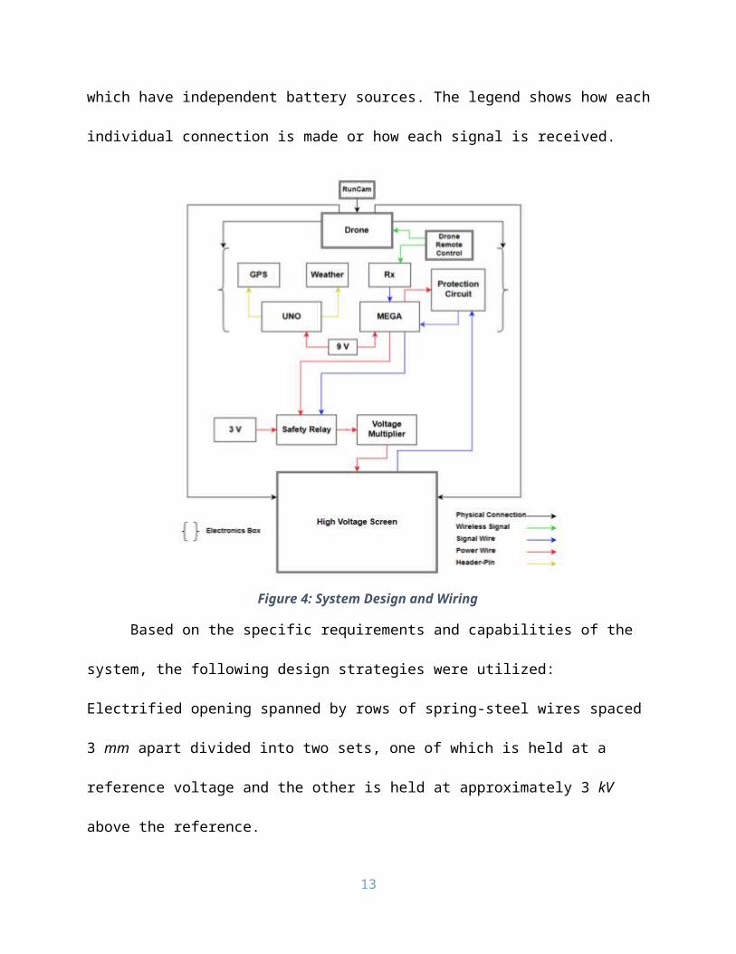
Results
During the Fall semester, the team successfully conducted two test flights. The first test
flight was conducted on September 15th, 2016 under Dr. Becker’s supervision. The flight was 43
minutes long and we collected a set of data of 52 strikes. The result yields about 1.2 strikes per
minute. At the time, the team was working on the weather module so we weren’t able to collect
environmental data. Fig. 5 is the plot of the first test, the red line represents the path of the drone
took and yellow dots are the strikes we collected from data acquisition module.
Figure 5: Flight Test Plot
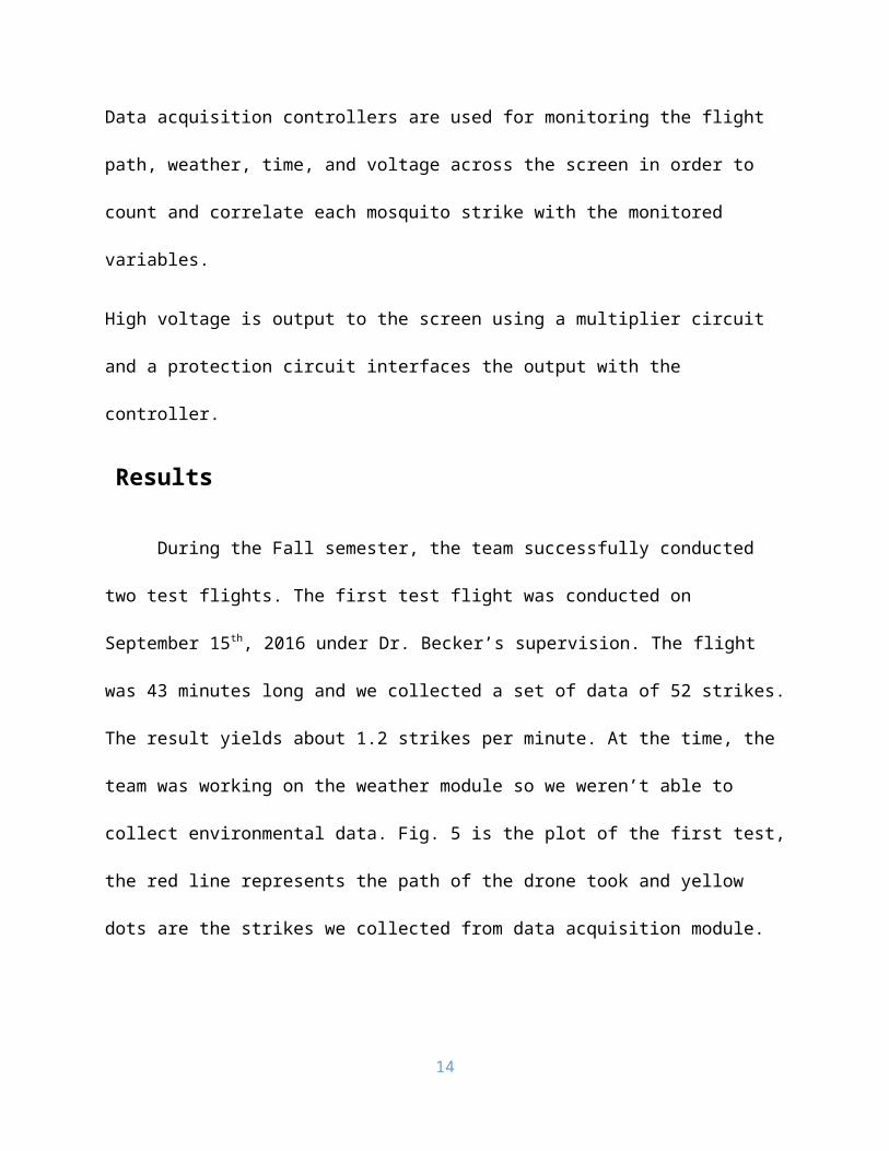
The final test was performed November 30th, 2016 by the team. The team decided to test
using 2 methods: Boustrophedon path and random path. We set up each test to be a 12-minute
duration. The weather conditions on test day were sunny with 8 mph wind speed. Fig. 6 shows
the result we got from the test. For the Boustrophedon path flight, we recorded sixty-nine strikes
from out data acquisition. For the random path flight, we recorded fifty-eight strikes.
10

Figure 6: Final Test, 2 Paths Tested
At the time of the second test, we successfully implemented the environmental sensor
alongside with data acquisition module. Fig. 7 shows the environmental conditions of the test
day. We collected humidity, temperature and pressure and plotted them with MATLAB. This
data could be used to assist Mosquito Control Division with their future researches and studies.
11
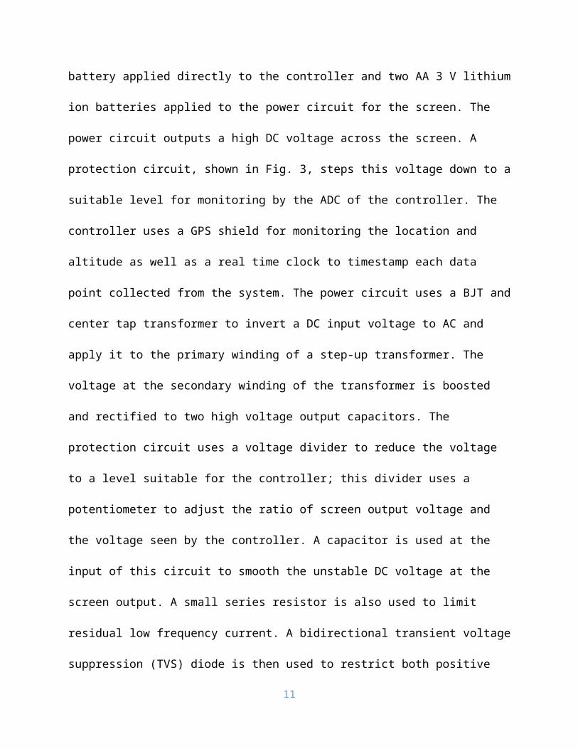
Figure 7: Weather Data Collected During Final Test
From the result above and compare to the goal that we set earlier in the semester, we
obtained an average of 5 zap per minute: 5.75 zap per minute for the Boustrophedon path and
4.83 zap per minute for the random path. We have the total weight of the system to be 5.645 lbs.
included all electronics and wires. This result exceeded our expectation of the goal we set in the
beginning of the year.
In our electronics aspect, we met our goal regarding the output voltage across the net. We
have around 3.4 kV across the net along with a significant larger amount of energy being pushed
to the net. We developed a modular capacitor bank at the output of the multiplier circuit which
capacitors can be added or removed easily on the spot. This way, we can adjust the energy stored
at the output.
12

Conclusions
Our team has experience in microelectronics, power, embedded programming, and
physical hardware implementation that will allow us to efficiently complete this project. The
design will be mountable to a drone and will be used to kill mosquitoes efficiently in an
environmentally safe manner. Additionally, we will collect all the data required for further
research on mosquitoes and useful for simulations involving electrical means to eliminate
mosquitoes. The ultimate purpose is to reduce human mortality due to mosquito borne diseases
and by eliminating mosquitoes and collecting meaningful data along the way, we can make this
happen.
Recommendations
The results show that our system is fully functional and well-suited for surveying and
tracking mosquito populations. However, we would recommend senior design students, who will
potentially take on our project, to implement a more advanced data acquisition system. The
project would have a significant reduction is size and weight if our microcontrollers are replaced
by a single computer such as BeagleBone or Raspberry Pi. Computers are faster than
microcontrollers, thus they process data from sensors at a faster sample rate and that would yield
us a better resolution of data collection. Moreover, data collected from an advanced computer
will be easier to process and generate results, plots, and even store in the cloud. In the other
word, a single computer will solve the problem of collecting data from 3 different memory cards
and process them with MATLAB.
Our pilot, An Nguyen, successfully implemented the autonomous feature where he can
program a path of coordinates and the drone will automatically fly along that path. This motion
control is such an advancement for our project. By working more on this motion control
13
technology, we could increase the feasibility of killing mosquitoes in large scale by means of
multiple drone in one area. This motion control algorithm will save money having an operator
for each drone and also decrease the possibility of drone crashes due to human errors.
The most important recommendation is to aggressively attack the problem of subsequent
strikes. The limitation of this design presented is the strikes at the output cannot occur nearly
simultaneous as the capacitors take several hundred milliseconds to fully recharge. This problem
exists because the small lightweight transformer used will short on the secondary winding if too
much energy is pushed through. On the ground this issue is more easily address because a large
fly back transformer can be used and plugged into mains voltage. Lots of energy can be pushed
through the heavy transformer and a more effective output bank can be designed. With a lighter
weight transformer and a lighter weight power source, it is more challenging to address this
problem.
14
Financial Summary
Table 1: Financial Summary
15

The final parts total for the project was $1,007.25. This is only $7.25 since over what the
team expected to spend. The labor total decreased from the 1st semester to the 2nd semester due to
the team having completed more than expected in the 1st semester and being ahead of schedule.
References
[1] C. J. Murray, L. C. Rosenfeld, S. S. Lim, K. G. Andrews, K. J. Foreman, D. Haring, N.
Fullman, M. Naghavi, R. Lozano, and A. D. Lopez, “Global malaria mortality between 1980
and 2010: a systematic analysis,” The Lancet, vol. 379, no. 9814, pp. 413–431, 2012.
[2] J. E. Parker, N. Angarita-Jaimes, M. Abe, C. E. Towers, D. Towers, and P. J. McCall,
“Infrared video tracking of anopheles gambiae at insecticide-treated bed nets reveals rapid
decisive impact after brief localised net contact,” Scientific reports, vol. 5, 2015.
[3] S. Butail, N. Manoukis, M. Diallo, A. S. Yaro, A. Dao, S. F. Traor´e, J. M. Ribeiro, T.
Lehmann, and D. A. Paley, “3d tracking of mating events in wild swarms of the malaria
mosquito anopheles gambiae,” in 2011 Annual International Conference of the IEEE
Engineering in Medicine and Biology Society. IEEE, 2011, pp. 720–723.
[4] G. M. Williams and J. B. Gingrich, “Comparison of light traps, gravid traps, and resting
boxes for west nile virus surveillance,” Journal of Vector Ecology, vol. 32, no. 2, pp. 285–
291, 2007.
[5] Y. Chen, A. Why, G. Batista, A. Mafra-Neto, and E. Keogh, “Flying insect classification
with inexpensive sensors,” Journal of insect behavior, vol. 27, no. 5, pp. 657–677, 2014.
[6] A. Linn, “Building a better mosquito trap,” International Pest Control, vol. 58, no. 4, p. 213,
2016.
16
[7] Varghese, Benson. "Drone Laws in Texas." Versus Texas. February 1, 2015. Accessed May
2, 2016. https://www.versustexas.com/criminal/drone-laws-in-texas/.
[8] "RoHS Compliance." RoHS Guide. Accessed May 2, 2016. http://www.rohsguide.com/.
Appendix A (Outside Reference Appendix)
Found in this appendix are major points of reference for key components of this project.
Additional in depth information can be found in folders accompanying this submission.
Output capacitors: 1000V 0.1uF 104J Metallized Polypropylene Film Capacitors
Product Name Metallized Polypropylene Film CapacitorModel CBB21Dielectric Material Metallized Polypropylene FilmWithstand Voltage 1000VCapacitance 0.1uFCapacitance Tolerance ±5%
Lead Spacing 15mm / 0.59"
Total Size (Each) 37 x 17 x 6mm / 1.46" x 0.67" x 0.24" (L*W*T)
Weight 16gColor As Picture ShownPackage Content 10 x Metallized Polypropylene Film Capacitors
Arduino Mega Technical Specifications:
Microcontroller ATmega2560
Operating Voltage 5V
Input Voltage (recommended) 7-12V
Input Voltage (limit) 6-20V
Digital I/O Pins 54 (of which 15 provide PWM output)
17

Analog Input Pins 16
DC Current per I/O Pin 20 mA
DC Current for 3.3V Pin 50 mA
Flash Memory 256 KB of which 8 KB used by bootloader
SRAM 8 KB
EEPROM 4 KB
Clock Speed 16 MHz
LED_BUILTIN 13
Length 101.52 mm
Width 53.3 mm
Weight 37 g
Arduino UNO Technical Specifications:
Microcontroller ATmega328P
Operating Voltage 5V
Input Voltage (recommended) 7-12V
Input Voltage (limit) 6-20V
Digital I/O Pins 14 (of which 6 provide PWM output)
PWM Digital I/O Pins 6
Analog Input Pins 6
DC Current per I/O Pin 20 mA
DC Current for 3.3V Pin 50 mA
Flash Memory 32 KB (ATmega328P)of which 0.5 KB used by bootloader
SRAM 2 KB (ATmega328P)
EEPROM 1 KB (ATmega328P)
18

Clock Speed 16 MHz
LED_BUILTIN 13
Length 68.6 mm
Width 53.4 mm
Weight 25 g
Protection Circuit Components:
LineNo.
Mouser Part NumberManufacturer Part Number
DescriptionQuantity Unit Price
USD
1 647-UVZ1HR22MDDUVZ1HR22MDD50volts 0.22uF (C1,C2,C3)
3 0.111
2 571-282834-5282834-5T-BLK 0254 05P S/E
1 2.670
3 512-BAT54SBAT54S30V 200mA (D1,D3,D5)
3 0.167
4 78-GSOT12C-G3-08GSOT12C-G3-08Bidirectional 2.2 V (D2,D4,D6)
3 0.292
5 579-MCP601T-I/OTMCP601T-I/OTSingle 2.7V (U1,U2,U3)
3 0.390
6 81-PV36W101C01B00PV36W101C01B00100ohms (R1,R12,R23)
3 1.160
7 81-PV36W103C01B00PV36W103C01B0010Kohms (R2,R13,R24)
3 1.160
Resistors: R3-R11, R14-R22, R25-R33 - 1 [MΩ]
19