aalborg universitet access control in iot/m2m - cloud...
TRANSCRIPT

Aalborg Universitet
Access Control in IoT/M2M - Cloud Platform
Anggorojati, Bayu
Publication date:2015
Document VersionAccepted author manuscript, peer reviewed version
Link to publication from Aalborg University
Citation for published version (APA):Anggorojati, B. (2015). Access Control in IoT/M2M - Cloud Platform. Department of Electronic Systems, AalborgUniversity.
General rightsCopyright and moral rights for the publications made accessible in the public portal are retained by the authors and/or other copyright ownersand it is a condition of accessing publications that users recognise and abide by the legal requirements associated with these rights.
? Users may download and print one copy of any publication from the public portal for the purpose of private study or research. ? You may not further distribute the material or use it for any profit-making activity or commercial gain ? You may freely distribute the URL identifying the publication in the public portal ?
Take down policyIf you believe that this document breaches copyright please contact us at [email protected] providing details, and we will remove access tothe work immediately and investigate your claim.
Downloaded from vbn.aau.dk on: juli 01, 2018
Access Control in IoT/M2M - CloudPlatform
Bayu AnggorojatiCenter for TeleInFrastruktur
a dissertation submitted tothe department of electronic systems of aalborg universityin partial fulfillment of the requirements for the degree of
doctor of philosophy
Supervisor:
Associate Professor Neeli Rashmi Prasad, Aalborg University, Denmark
Professor Ramjee Prasad, Aalborg University, Denmark
The examination committee:
Professor Josef Noll
Professor Milica Pejanovic-Djurisic
Associate Professor Zheng-Hua Tan (Chairman)
Moderator:
Associate Professor Albena Mihovska
Date of defence: 25 February 2015
ISSN: *** - ****
ISBN: 978-87-7152-064-4
Copyright c⃝ 2015 by Bayu Anggorojati
Center for TeleInFrastruktur
All rights reserved. No part of the material protected by this copyright notice may
be reproduced or utilized in any form or by any means, electronic or mechanical, in-
cluding photocopying, recording or by any information storage and retrieval system,
without written permission from the author.
Mandatory page
Thesis title: Access Control in IoT/M2M - Cloud Platform
Name of PhD student: Bayu Anggorojati
Name and title of supervisors:
• Associate Professor Neeli Rashmi Prasad
• Professor Ramjee Prasad
List of published papers:
• B. Anggorojati, N.R. Prasad, R. Prasad, “Efficient Fine Grained Ac-cess Control for RFID Inter-Enterprise System,” Journal of Cyber Secu-rity and Mobility, vol. 2, no. 3 & 4, pp. 221-242, 2013
• P.N. Mahalle, B. Anggorojati, N.R. Prasad, R. Prasad, “Identity Au-thentication and Capability Based Access Control (IACAC) for the In-ternet of Things,” Journal of Cyber Security and Mobility, vol. 1, no. 4,pp. 309-348, 2013.
• B. Anggorojati, P.N. Mahalle, N.R. Prasad, R. Prasad, ”Secure Ac-cess Control and Authority Delegation based on Capability and ContextAwareness for Federated IoT,” Internet of Things and M2M Commu-nications. ed. / Fabrice Theoleyre; Ai-Chun Pang. Denmark : RiverPublisher, 2013. p. 135-160 (The River Publishers Series in InformationScience and Technology).
• B. Anggorojati, N.R. Prasad, R. Prasad, “Secure Capability-basedAccess Control in the M2M Local Cloud Platform,” Wireless Commu-nications, Vehicular Technology, Information Theory and Aerospace &Electronic Systems Technology (Wireless VITAE), 2014 IEEE 4th Inter-national Conference on, May, 2014.
iii

• B. Anggorojati, N.R. Prasad, R. Prasad, “An Intrusion DetectionGame in Access Control System for the M2M Local Cloud Platform,”the 19th Asia Pasific Conference on Communications (APCC) 2013, Bali,Indonesia, 2013.
• B. Anggorojati, P.N. Mahalle, N.R. Prasad, R. Prasad, “Efficient andScalable Location and Mobility Management of EPCglobal RFID Sys-tem,” the 16th WPMC, Atalantic City, NJ, USA, 2013.
• B. Anggorojati, P.N. Mahalle, N.R. Prasad, R. Prasad, ”Capability-based Access Control Delegation Model on the Federated IoT Network,”the 15th WPMC, Taipei, Taiwan, 2012.
• P.N. Mahalle, B. Anggorojati, N.R. Prasad, R. Prasad, ”Identity drivenCapability based Access Control (ICAC) scheme for the Internet of Things,”the 6th IEEE ANTS, Bengaluru, India, 2012.
• P.N. Mahalle, B. Anggorojati, N.R. Prasad, R. Prasad, ”Identity Es-tablishment and Capability Based Access Control (IECAC) Scheme forInternet of Things,” the 15th WPMC, Taipei, Taiwan, 2012.
This thesis has been submitted for assessment in partial fulfillment of the PhDdegree. The thesis is based on the submitted or published scientific paperswhich are listed above. Parts of the papers are used directly or indirectlyin the extended summary of the thesis. As part of the assessment, co-authorstatements have been made available to the assessment committee and are alsoavailable at the Faculty. The thesis is not in its present form acceptable foropen publication but only in limited and closed circulation as copyright maynot be ensured.
iv

Abstract
Billions of devices are connected to the Internet nowadays, and the numberwill continue to grow in the future thanks to the advances in the electronicsand telecommunication technology developments. Its application in broad as-pects of human’s life brings a lot of benefits by improving productivity andquality of life. This paradigm, which is often called Internet of Things (IoT)or Machine-to-Machine (M2M), will provide an unprecedented opportunity tocreate applications and services that go far beyond the mere purpose of eachparticipant.
Many studies on the both technical and social aspects of IoT have shownthat the concern about the security and privacy play a huge role for the massadoption of the IoT/M2M as cloud services. Among the important topicswithin the security and privacy, the access control is an important mechanism,which essentially manages how the important assets or resource of a systemcan be accessed by other parties by means of a set of access policies.
For an IoT system such as Radio Frequency Identification (RFID) that col-lects huge amounts of RFID events data and may store it in the cloud storagefor tracking purpose, access control to such data becomes a critical point tothe privacy of the enterprises as well as the customers. Certainly, designingan access control to the RFID events data with high-granularity is desirableto maintain the privacy while allowing external party to perform tracking andtracing of RFID tags. In addition, mobility or location management also playsa big role to perform tracking of RFID tags. Scalability and efficiency are twoimportant requirements in location management when big numbers of tags aremoving from one reading location to the others, i.e. being mobile. Thus, de-signing a fine-grained access control along with scalable location managementin RFID system is of paramount importance.
A distributed cloud platform approach for the IoT/M2M, which consists ofa set of IoT/M2M gateways, is introduced to cope with some inherent issuesof IoT network which is highly heterogeneous and distributed in nature. As a
v

result, access control becomes even more challenging when such approach -alsocalled as local cloud - which may consist of devices with low computationalcapacity, is used. As each of the IoT/M2M gateways may have different as-sets or resources, and thus different access policies, combining different policiesand to make an access control decision in distributed manner is a very chal-lenging task. In addition, the access control system should also fulfill otherrequirements in terms of scalability, context-awareness, flexibility, and attackresilience. These challenges lead us to come up with capability-based accesscontrol that can be easily distributed, i.e. scalable and suitable for distributedsystem, and propagated, i.e. allow flexible access delegation. On top of that,contextual information can also be included in the capability data structure soas to deal with dynamic context in IoT/M2M environment. However, thoroughdesign of capability-based access control is needed, especially to keep the ac-cess delegation through capability propagation under control and to maintainsecure access control.
To detect and mitigate various threats, especially the insider threat, withinthe IoT/M2M local cloud platform is a difficult task for the access controlsystem. Thus, an Intrusion Detection System (IDS) is needed as the integralpart of the access control system. We can imagine a situation where a maliciousnode disguises as a good node such that it can join the local cloud, but onceit becomes part of the cloud it would cause a huge damage to the system.For example it could manipulate access right of an actuator controlled by agateway, e.g. to open a gate or turning on or off some switches, stealingsome sensitive data from sensors, and so on. Keeping in mind such threatand the fact that minimum human interaction is needed in the local cloudenvironment, the IDS should be able to learn and update its knowledge basedon the interaction with the other nodes. This leads us to study, model, andanalyze the interactions between malicious node and regular node equippedwith IDS with game theory, in order to suggest the best strategies for bothsides. The study also includes a general fact that each node has a set of assets orresources with different values. Finally, an optimum strategy for both attackerand defender will be derived by considering their respective costs and benefits.
vi

Dansk Resume
Milliarder af apparater er forbundet til internettet i disse dage og antal af disseapparater vil stige i fremtiden takket være udviklingen i elektronik og telekom-munikation. Dens anvendelse i flere aspekter af menneskeliv har bragt en massefordele ved at forbedre produktivitet og livskvalitet. Dette paradigme, som oftehedder Internet of Things (IoT) eller Machine-to-Machine (M2M), vil give enhidtil uset mulighed for at skabe applikationer og tjenester, som strækker langtover det behov, som hver forbruger har.
En del studier pa bade de tekniske og sociale aspekter af IoT har indikeret,at bekymringen for sikkerhed og privatliv spiller en stor rolle for anvendelse afIoT/M2M som cloud services. Udover sikkerhed og privatliv er adgangskontrologsa en vigtig mekanisme, som essentielt styrer vigtigheden af andre partiertil at fa adgang til et systems aktiv eller ressourcer ved hjælp af et sæt afadgangspolitikker. For et IoT system sasom Radio Frequency Identification(RFID), som samler store mængder RFID events data og som kan opbevaresi cloud storage saledes for at kunne bliver sporet, adgangskontrol til dataenebliver et vigtigt punkt for virksomhedernes og kundernes privatliv. At designeen adgangskontrol til RFID events data med en høj nøjagtighed er bestemtønsket for at kunne opretholde privatlivet og samtidig tillade eksterne partier atforetage sporingen af RFID tags. Ydermere spiller mobilitets og beliggenhedstyring ogsa en stor rolle i at foretage sporing af RFID tags. Skalerbarhedog effektivitet er de to vigtige krav i styringen af beliggenheden nar storemængder af data bevæger sig fra en læsebeliggenhed til andre beliggenhederved eksempelvis at være bevægelig. Derfor er det vigtigt at designe en finkornetadgangskontrol sammen med en skalerbar beliggenhedstyring i RFID systemet.
En distribueret skyplatform tilgang til IoT/M2M, som bestar af et sætIoT/M2M gateways, er blevet introduceret for at kunne handtere nogle iboendesager vedr. IoT netværk, som i høj grad er forskellige og distribueret af karak-ter. Dette medfører, at adgangskontrollen bliver mere udfordrende nar deranvendes sadan en tilgang, som ogsa hedder local cloud og som kan besta af
vii

apparater med en lav beregningsmæssig kapacitet. Da hver IoT/M2M gate-way kunne have forskellige aktiver eller ressourcer og dermed ogsaforskelligeadgangspolitikker, at kombinere diverse politikker og foretage en beslutning omhandteringen af adgangskontrollen er en meget krævende opgave. Desuden skaladgangskontrolsystemet ogsa opfylde andre krav med henblik pa skalerbarhed,kontekstbevidsthed, fleksibilitet og angrebsmodstandskraft. Disse udfordringerleder frem til udviklingen af en kapacitetsbaseret adgangskontrol, som let kandistribueres ved fx at være skalerbar og egnet til et distribueret og spredtsystem. Et distribueret og spredt system angiver hermed en fleksibel adgang-suddelegering. Oven i købet vil kontekstuelle data ogsa kunne være inkludereti kapacitetsdatastrukturen for at kunne handtere den dynamiske kontekst iIoT/M2M miljøet. Det skal dog bemærkes, at der skal et grundigt designaf en kapacitetsbaseret adgangskontrol til for at styre adgangsuddelegeringengennem kapacitetspredningen og for at opretholde en sikker adgangskontrol.
At detektere og afbøde forskellige trusler, især interne trusler i IoT/M2Mlokal skyplatform, er en besværlig opgave for adgangskontrolsystemet. Derforer det nødvendigt at have en Intrusion Detection System (IDS) som en cen-tral del af adgangskontrolsystemet. Man kan forestille sig en situation, hvoren farlig node skjuler sin identitet og lader som om, den er en ufarlig node.Nar truslen trænger ind i den lokale sky kan den faktisk medføre en stor ogalvorlig skade pa systemet. For eksempel kan den manipulere en aktuatorsadgangsret, som er styret af en gateway ved at lukke op for indgangen i sys-temet eller slukke nogle knapper i systemet, at stjæle nogle ømtalelige data frasensorerne, osv. Af hensyn til sadanne trusler og nødvendigheden af minimummenneskeinteraktionen i det lokale skymiljøburde IDS kunne lære og opdateredets viden pa baggrund af interaktionen med andre noder. Dette fører frem tilat studere, analysere og modellere interaktioner mellem farlige og almindeligenoder forsynet med IDS med spilteori for at kunne anbefale de bedste strate-gier for begge parter. Studiet omfatter ogsa faktummet, at hver node har enrække aktiver eller ressourcer med forskellige værdier. Endelig vil en optimalstrategi for bade angriber og forsvarer kunne opnas ved at tage højde for deresrespektive omkostninger og fordele.
viii

Table of Contents
Mandatory page iii
Abstract v
Dansk Resume vii
List of Figures xiii
List of Tables xv
1 Introduction 11.1 Motivation . . . . . . . . . . . . . . . . . . . . . . . . . . . . . . 11.2 Internet of Things (IoT)/Machine-to-Machine (M2M) and Cloud
Service: An Introduction . . . . . . . . . . . . . . . . . . . . . . 41.3 State of the Art: IoT/M2M Cloud Platform and the Enabling
Technologies . . . . . . . . . . . . . . . . . . . . . . . . . . . . . 61.3.1 IoT/M2M Physical Sensing: RFID as an Identification,
Sensing, and Communication Technology . . . . . . . . . 71.3.2 IoT/M2M Middleware: Open RFID Middleware platform 111.3.3 IoT/M2M Networking Architecture, Components, and
Protocols . . . . . . . . . . . . . . . . . . . . . . . . . . 171.3.4 IoT/M2M Cloud Platforms . . . . . . . . . . . . . . . . 20
1.4 Challenges of the IoT/M2M System . . . . . . . . . . . . . . . . 281.4.1 Security and Privacy . . . . . . . . . . . . . . . . . . . . 281.4.2 Distributed architecture . . . . . . . . . . . . . . . . . . 29
1.5 Problem statement and research questions . . . . . . . . . . . . 311.6 Hypotheses and research methodology . . . . . . . . . . . . . . 32
1.6.1 Hypotheses . . . . . . . . . . . . . . . . . . . . . . . . . 321.6.2 Methodology . . . . . . . . . . . . . . . . . . . . . . . . 33
1.7 Research goals and scope . . . . . . . . . . . . . . . . . . . . . . 341.7.1 Research goals . . . . . . . . . . . . . . . . . . . . . . . . 341.7.2 Scope of the research . . . . . . . . . . . . . . . . . . . . 35
ix

TABLE OF CONTENTS
1.8 Overview of the dissertation and scientific contributions . . . . . 361.9 References . . . . . . . . . . . . . . . . . . . . . . . . . . . . . . 41
2 Efficient Fine-Grained Access Control for Radio FrequencyIDentification (RFID) Inter-Enterprise Middleware System 472.1 Introduction . . . . . . . . . . . . . . . . . . . . . . . . . . . . . 482.2 Related works . . . . . . . . . . . . . . . . . . . . . . . . . . . . 492.3 Problem descriptions and the system requirements . . . . . . . . 502.4 Access control model . . . . . . . . . . . . . . . . . . . . . . . . 52
2.4.1 Assumptions . . . . . . . . . . . . . . . . . . . . . . . . . 522.4.2 Definitions . . . . . . . . . . . . . . . . . . . . . . . . . . 532.4.3 Access rules evaluation . . . . . . . . . . . . . . . . . . . 56
2.5 System Implementation . . . . . . . . . . . . . . . . . . . . . . . 582.5.1 System architecture . . . . . . . . . . . . . . . . . . . . . 582.5.2 XML specification of access control policy . . . . . . . . 59
2.6 Evaluation results and analysis . . . . . . . . . . . . . . . . . . 632.6.1 Evaluation procedures . . . . . . . . . . . . . . . . . . . 642.6.2 The impact of varying the number of read tags . . . . . 652.6.3 The impact of the number of the Electronic Product
Code Information System (EPCIS) events data in therepository . . . . . . . . . . . . . . . . . . . . . . . . . . 66
2.7 Discussions . . . . . . . . . . . . . . . . . . . . . . . . . . . . . 672.8 Conclusion . . . . . . . . . . . . . . . . . . . . . . . . . . . . . . 682.9 References . . . . . . . . . . . . . . . . . . . . . . . . . . . . . . 70
3 Secure Open M2M-RFID Middleware 733.1 Introduction . . . . . . . . . . . . . . . . . . . . . . . . . . . . . 743.2 Related Works . . . . . . . . . . . . . . . . . . . . . . . . . . . . 75
3.2.1 Contributions to the existing works . . . . . . . . . . . . 763.3 Proposed architecture . . . . . . . . . . . . . . . . . . . . . . . . 77
3.3.1 EPCglobal RFID Middleware – Session Initiation Pro-tocol (SIP) Architecture . . . . . . . . . . . . . . . . . . 77
3.3.2 SIP Protocol . . . . . . . . . . . . . . . . . . . . . . . . 793.3.3 Access Control Module . . . . . . . . . . . . . . . . . . . 80
3.4 The Testbed implementation . . . . . . . . . . . . . . . . . . . . 813.5 Results and discussion . . . . . . . . . . . . . . . . . . . . . . . 84
3.5.1 Measurement procedures . . . . . . . . . . . . . . . . . . 843.5.2 Analysis of measurement results . . . . . . . . . . . . . . 853.5.3 The impact of access control in the tags tracking case . . 88
3.6 Conclusion . . . . . . . . . . . . . . . . . . . . . . . . . . . . . . 903.7 References . . . . . . . . . . . . . . . . . . . . . . . . . . . . . . 91
x

TABLE OF CONTENTS
4 Secure Access Control and Authority Delegation based on Ca-pability and Context Awareness for IoT 934.1 Introduction . . . . . . . . . . . . . . . . . . . . . . . . . . . . . 944.2 Related Works on Access Control and Authority Delegation
Models . . . . . . . . . . . . . . . . . . . . . . . . . . . . . . . . 954.2.1 Contributions to the existing works . . . . . . . . . . . . 97
4.3 System Architecture . . . . . . . . . . . . . . . . . . . . . . . . 974.3.1 System architecture to support the Capability-based Context-
Aware Access Control (CCAAC) model . . . . . . . . . . 974.3.2 Federated-IoT . . . . . . . . . . . . . . . . . . . . . . . . 98
4.4 Proposed CCAAC Model . . . . . . . . . . . . . . . . . . . . . . 1014.4.1 Proposed capability structure in CCAAC . . . . . . . . . 1014.4.2 Basic definitions . . . . . . . . . . . . . . . . . . . . . . . 102
4.5 Specification of CCAAC Mechanisms . . . . . . . . . . . . . . . 1044.5.1 Creation . . . . . . . . . . . . . . . . . . . . . . . . . . . 1054.5.2 Access Provision . . . . . . . . . . . . . . . . . . . . . . 106
4.6 Secure CCAAC based Delegation Framework . . . . . . . . . . . 1094.6.1 High level delegation model . . . . . . . . . . . . . . . . 1094.6.2 Delegation mechanism based on CCAAC . . . . . . . . . 110
4.7 Evaluation and analysis . . . . . . . . . . . . . . . . . . . . . . 1134.7.1 Evaluation procedure . . . . . . . . . . . . . . . . . . . . 1134.7.2 The secrecy . . . . . . . . . . . . . . . . . . . . . . . . . 1144.7.3 The authentication . . . . . . . . . . . . . . . . . . . . . 115
4.8 Conclusion . . . . . . . . . . . . . . . . . . . . . . . . . . . . . . 1154.9 References . . . . . . . . . . . . . . . . . . . . . . . . . . . . . . 117
5 Capability-based access control in the M2M local cloud plat-form: A practical implementation perspective 1195.1 Introduction . . . . . . . . . . . . . . . . . . . . . . . . . . . . . 1205.2 System Description . . . . . . . . . . . . . . . . . . . . . . . . . 121
5.2.1 BETaaS architecture . . . . . . . . . . . . . . . . . . . . 1215.2.2 Security manager . . . . . . . . . . . . . . . . . . . . . . 1225.2.3 Access to BETaaS platform . . . . . . . . . . . . . . . . 125
5.3 The proposed approach . . . . . . . . . . . . . . . . . . . . . . . 1265.3.1 Capability design . . . . . . . . . . . . . . . . . . . . . . 1275.3.2 Capability creation . . . . . . . . . . . . . . . . . . . . . 1285.3.3 Access right delegation mechanism . . . . . . . . . . . . 1295.3.4 Capability access evaluation . . . . . . . . . . . . . . . . 1305.3.5 Capability revocation . . . . . . . . . . . . . . . . . . . . 130
5.4 Use cases . . . . . . . . . . . . . . . . . . . . . . . . . . . . . . 1305.4.1 GW joining process . . . . . . . . . . . . . . . . . . . . . 130
xi
TABLE OF CONTENTS
5.4.2 Application installation . . . . . . . . . . . . . . . . . . . 1325.5 Conclusion . . . . . . . . . . . . . . . . . . . . . . . . . . . . . . 1335.6 References . . . . . . . . . . . . . . . . . . . . . . . . . . . . . . 134
6 Intrusion Detection Game in Access Control System for theM2M Local Cloud Platform: A Game Theoretical Approach 1356.1 Introduction . . . . . . . . . . . . . . . . . . . . . . . . . . . . . 1366.2 Related works . . . . . . . . . . . . . . . . . . . . . . . . . . . . 1376.3 The M2M local cloud system and security consideration . . . . . 1386.4 Single stage game model . . . . . . . . . . . . . . . . . . . . . . 140
6.4.1 Sensible set of assets . . . . . . . . . . . . . . . . . . . . 1436.5 Proposed multi-stage Bayesian game . . . . . . . . . . . . . . . 143
6.5.1 Perfect Bayesian Equilibrium (PBE) analysis . . . . . . . 1466.6 Numerical analysis . . . . . . . . . . . . . . . . . . . . . . . . . 1506.7 Conclusion . . . . . . . . . . . . . . . . . . . . . . . . . . . . . . 1556.8 References . . . . . . . . . . . . . . . . . . . . . . . . . . . . . . 157
7 Conclusions 1597.1 Access control and mobility management in RFID middleware . 1597.2 Capability-based access control for IoT/M2M networks and cloud
platform . . . . . . . . . . . . . . . . . . . . . . . . . . . . . . . 1617.3 Intrusion detection in access control system for M2M local cloud
platform . . . . . . . . . . . . . . . . . . . . . . . . . . . . . . . 1627.4 Future directions . . . . . . . . . . . . . . . . . . . . . . . . . . 163
A Publications 165A.1 Journal paper . . . . . . . . . . . . . . . . . . . . . . . . . . . . 165A.2 Book chapter . . . . . . . . . . . . . . . . . . . . . . . . . . . . 165A.3 Conference papers . . . . . . . . . . . . . . . . . . . . . . . . . . 166
A.3.1 First Author . . . . . . . . . . . . . . . . . . . . . . . . . 166A.3.2 Co-author . . . . . . . . . . . . . . . . . . . . . . . . . . 166
A.4 Project deliverables . . . . . . . . . . . . . . . . . . . . . . . . . 167
xii
List of Figures
1.1 EPC tag ID format . . . . . . . . . . . . . . . . . . . . . . . . . 101.2 EPCglobal overall architecture, components and layers [12] . . . 121.3 RFID Middleware architecture of ASPIRE based on EPCGlobal
architecture framework [7] . . . . . . . . . . . . . . . . . . . . . 131.4 The IPv6 over Low-powerWireless Personal Area Network (6LoWPAN)
architecture . . . . . . . . . . . . . . . . . . . . . . . . . . . . . 181.5 Example of Personal Network (PN) architecture . . . . . . . . . 191.6 Users and providers relationships in cloud computing . . . . . . 201.7 Cloud service models . . . . . . . . . . . . . . . . . . . . . . . . 231.8 Overview of Xively Cloud Services . . . . . . . . . . . . . . . . . 251.9 IoT-A security features . . . . . . . . . . . . . . . . . . . . . . . 261.10 Correlation of dissertation chapters . . . . . . . . . . . . . . . . 40
2.1 The interactions of EPCIS repository interfaces in an inter-enterprise RFID system . . . . . . . . . . . . . . . . . . . . . . 51
2.2 System architecture of the implemented access control model . . 582.3 Query delay time for different number of tags with 95% confi-
dence interval . . . . . . . . . . . . . . . . . . . . . . . . . . . . 652.4 Query delay time for different number EPCIS events in the
repository with 95% confidence interval . . . . . . . . . . . . . . 66
3.1 Proposed EPCglobal-SIP architecture . . . . . . . . . . . . . . . 773.2 Proposed EPCglobal-SIP architecture . . . . . . . . . . . . . . . 813.3 Tag registration procedure . . . . . . . . . . . . . . . . . . . . . 823.4 Tag tracking procedure . . . . . . . . . . . . . . . . . . . . . . . 833.5 Tag tracking procedure with access control . . . . . . . . . . . . 833.6 Time consumed in the registration process for different number
of tags with 95% confidence interval . . . . . . . . . . . . . . . . 853.7 Time consumed in the tag tracking for different number of tags
with 95% confidence interval . . . . . . . . . . . . . . . . . . . . 863.8 CDF plot of the proposed method in the registration processes
for various tags numbers . . . . . . . . . . . . . . . . . . . . . . 87
xiii
LIST OF FIGURES
3.9 CDF plot of the proposed method in the tracking processes forvarious tags numbers . . . . . . . . . . . . . . . . . . . . . . . . 88
3.10 The impact of access control on the time consumed in the tagstracking for different number of tags with 95% confidence interval 89
4.1 System architecture for supporting the CCAAC . . . . . . . . . 984.2 An example of Federated IoT network with delegation scenario . 994.3 Capability creation protocol in the proposed access control mech-
anism . . . . . . . . . . . . . . . . . . . . . . . . . . . . . . . . 1054.4 Capability access protocol in the proposed access control mech-
anism . . . . . . . . . . . . . . . . . . . . . . . . . . . . . . . . 1084.5 High level delegation model on Federated-IoT . . . . . . . . . . 1104.6 Capability propagation protocol for authority delegation in our
proposed access control . . . . . . . . . . . . . . . . . . . . . . . 111
5.1 High level architecture of the Building the Environment forThing as a Service (BETaaS) platform . . . . . . . . . . . . . . 122
5.2 The interaction of the Security Manager with the other Managers1255.3 Capability creation and delegation during GW joining process . 1315.4 Capability delegation during application installation process . . 132
6.1 High level architecture of the M2M local cloud system based onBETaaS . . . . . . . . . . . . . . . . . . . . . . . . . . . . . . . 140
6.2 Illustration of the player D ’s posterior belief update in the multi-stage Bayesian game . . . . . . . . . . . . . . . . . . . . . . . . 145
6.3 Player D ’s posterior belief update µD(θA1|·) upon its observationto player A’s action on the asset i = 1 . . . . . . . . . . . . . . 152
6.4 Player D ’s posterior belief update µD(θA1|·) upon its observationto player A’s action on the asset i = 5 . . . . . . . . . . . . . . 152
6.5 Player A’s best strategy p∗ in each stage game over the mostvaluable assets . . . . . . . . . . . . . . . . . . . . . . . . . . . . 153
6.6 Players A’s and D ’s overall payoffs in each stage game . . . . . 1536.7 Players A’s and D ’s average utilities deviations, i.e.
∣∣U ′A − UA
∣∣and
∣∣U ′D − UD
∣∣ vs x′
x, from the variation of detection rate, with
x = 83.33% and y = 0.29% . . . . . . . . . . . . . . . . . . . . . 1546.8 Players A’s and D ’s average utilities deviations, i.e.
∣∣U ′A − UA
∣∣and
∣∣U ′D − UD
∣∣ vs y′
y, from the variation of false alarm rate, with
x = 83.33% and y = 0.29% . . . . . . . . . . . . . . . . . . . . . 154
xiv
List of Tables
1.1 Summary of RFID systems operating at different frequencies . . 9
2.1 The grammar of of XProfiles in XML representation . . . . . . 602.2 The grammar of XObjects in XML representation . . . . . . . . 612.3 The grammar of XEventAttribute in XML representation . . . 612.4 The grammar of XRules in XML representation . . . . . . . . . 622.5 The grammar of Logical Expression in XML representation . . . 632.6 The grammar of XPolicies in XML representation . . . . . . . 63
3.1 95% confidence interval values of the measured data . . . . . . . 87
4.1 Notations used in the CCAAC definition . . . . . . . . . . . . . 101
6.1 Strategic form of the attacker/defender Bayesian game for theasset i . . . . . . . . . . . . . . . . . . . . . . . . . . . . . . . . 142
6.2 Mixed equilibrium strategies . . . . . . . . . . . . . . . . . . . . 151
xv


List of Acronyms
FI Future Internet
EC European Commission
M2M Machine-to-Machine
ITS Intelligent Transport System
IETF Internet Engineering Task Force
MANET Mobile Ad-hoc NETwork
CCAAC Capability-based Context-Aware Access Control
IoT Internet of Things
ITU-T International Telecommunication Union - TelecommunicationStandardization Sector
WSN Wireless Sensor Network
NFC Near Field Communication
ICAP Identity based Capability
VID Virtual Identity
MAGNET My Adaptive Global NETwork
CASM Context Aware Security Manager
PN Personal Network
ACS Access Control Servers
ACL Access Control List
ACM Access Control Matrix
xvii
LIST OF TABLES
RBAC Role Based Access Control
ABAC Attribute Based Access Control
XACML Extensible Access Control Markup Language
GTRBAC General Temporal RBAC
TRBAC Temporal RBAC
CARBAC Context Aware Role Based Access Control
XML Extensible Markup Language
PTD Personal Trusted Device
WAN Wide Area Network
WWAN Wireless Wide Area Network
WLAN Wireless Local Area Network
WPAN Wireless Personal Area Network
PAN Personal Area Network
CA Certificate Authority
PN-F Personal Network Federation
AVISPA Automated Validation of Internet Security Protocols andApplications
IdP Identity Provider
SDP Security Decision Point
6LoWPAN IPv6 over Low-power Wireless Personal Area Network
LoWPAN Low-power Wireless Personal Area Network
DHT Distributed Hash Table
P2P Peer-to-Peer
RP Reader Protocol
LLRP Low Level Reader Protocol
xviii

LIST OF TABLES
ALE Application Level Events
HAL Hardware Abstraction Layer
FC Filtering and Collection
BEG Business Event Generator
EPCIS Electronic Product Code Information System
ONS Object Name Server
NAPTR Naming Authority PoinTeR
TDS Tag Data Standard
TDT Tag Data Translation
JAXB Java Architecture for XML Binding
SOAP Simple Object Access Protocol
RDBMS Relational Data Base Management System
AAL Auto-ID Authorization Language
SQL Structured Query Language
SIP Session Initiation Protocol
VoIP Voice over IP
IMS IP Multimedia Subsystem
SUA Surrogate User Agent
SIMPLE SIP for Instant Messaging and Presence Leveraging Extension
SNS SRMS Name Server
SRV SeRVice
RF Radio Frequency
EPC Electronic Product Code
ICT Information and Communication Technology
IoT Internet of Things
xix

LIST OF TABLES
NFC Near Field Communication
RFID Radio Frequency IDentification
XML eXtensible Markup Language
DNS Domain Name System
URI Uniform Resource Identifier
IP Internet Protocol
NGN Next Generation Network
JSON Java Script Object Notation
GPS Global Positioning System
CDF Cummulative Distribution Function
API Application Programming Interface
PKI Public Key Infrastructure
ECC Elliptic Curve Cryptography
ECMQV Elliptic Curve Menezes-Qu-Vanstone
SaaS Software as a Service
PaaS Platform as a Service
IaaS Infrastructure as a Service
TaaS Thing as a Service
ASPIRE Advance Sensors and Programmable middleware for InnovativeRfid Enterprise applications
ISISEMD Intelligent System for Independent living and SElfcare of seniorswith cognitive problems or Mild Dementia
BETaaS Building the Environment for Thing as a Service
IDS Intrusion Detection System
PBE Perfect Bayesian Equilibrium
NE Nash Equilibrium
xx

LIST OF TABLES
CoAP Constrained Application Protocol
MQTT Message Queuing Telemetry Transport
CRM Customer Relationship Management
NIST National Institute of Standards and Technology
SEC Standard of Efficient Cryptography
xxi


1Introduction
The goal of this chapter is to motivate the necessities in securing, as well asensuring the privacy and trust, of the Internet of Things (IoT)/Machine-to-Machine (M2M) and Cloud, by taking into consideration the huge demands ofsuch applications nowadays and in the future. The glimpse of the key issues istaken in this chapter which are identified and addressed in the dissertation. Itincludes explanation of contributions of the dissertation and related publica-tions which are provided. Finally, outline of the thesis is specified that givesan overview of the individual chapters.
1.1 Motivation
Billions of devices are connected to the internet nowadays, and the numberwill continue to grow in the future. As documented in [37] back in 2004, Har-bor Research, a technology consultancy and analysis firm, predicted that by2010, at least 1.5 billion devices will be Internet-connected worldwide. Someadvances in the electronics and telecommunication technology developments inrecent years, especially in wireless communication, that result in various kindsof tiny yet powerful devices with communication and networking capabilities,have attracted the industries to adopt this technology into their everyday busi-ness, so as to increase their efficiency, i.e. saving time, money or both [14].
1

Chapter 1
Moreover, there is also a huge demands in other sector other than industrialsector, such as public service, assisted living, etc, for this Information andCommunication Technology (ICT) developments.
Therefore, this calls the needs to a new paradigm in machine-to-machinecommunication which enables object or ”things” connectivity to the globalinternet network. This paradigm has been ”popularized” in the recent yearsby the term IoT or M2M. Before going even further, it is important to notethat the term IoT and M2M are often referring to the same thing or usedinterchangeably. One of the articles found in the literature that use both of theterm Internet of Things and M2M is [14]. The article was entitled ”The Internetof Things”, and the author of this article said that M2M communicationswould bring about a new wave of growth in the global economy driven bybillions of electronic and electromechanical devices being connected to theInternet. In the recent years, the terms M2M/IoT have been used together inmany scientific conferences within the field of Information and CommunicationTechnology.
The vision of connecting billions and even trillions of devices to the internethave come closer to the realization nowadays, driven by many kinds of appli-cations that not only concern with the industries but also the government aswell as public institution, and even everyday people’s life. For instance, smartgrid and smart metering allow the electrical utility companies to monitor thesupply of electrical power by power plants, including those that are ownedby private house, especially the ones with renewable energy sources, and theenergy demands by means of monitoring devices, e.g. wireless sensors. More-over, the electricity prices that are based on supply and demand can also bemonitored by the users, so as they can utilize their electrical appliances whenthe electricity price goes low due to high supply and so on. Another example isthe Intelligent Transport System (ITS) application in which information aboutthe traffic in a city can be monitored by wireless sensors or video surveillance,and then communicated to the users on their mobile devices with the helpof a Global Positioning System (GPS) transceiver, so that users will get theinformation about the best route by avoiding traffic jam, or the road accidentcan be prevented due to bad road condition, bad weather, natural disaster, e.g.avalanche, landslide, or flood, and so on. In fact, there are a lot more examplesand applications in different areas that can utilize the M2M or IoT, such ase-Health, smart home and building, environment monitoring, etc. All thoseexamples show that massive amount of data generated by billions of deviceswill be transferred through the network, and eventually the internet. In onehand, it opens a completely new opportunities and business models, especiallyto telecommunication industries due to high amount of generated data traffic
2

1.1. Motivation
as well as to the ICT players in general, and also growth in the global economyin general. On the other hand, it leaves some problems and challenges to betackled, in particular the security and privacy issues.
Another statement that can support the previous paragraph can be found in[15], in which US National Intelligence Council (NIC) in its Conference Reporton Disruptive Civil Technologies has included IoT as one of ”Six Technologieswith Potential Impacts on US Interests out to 2025”. It was foreseen that theinternet nodes will reside in almost all everyday things such as food packages,furniture, paper documents, and more, and therefore, it could contribute in-valuably to the economy. Besides the potential opportunities of IoT to the USeconomy, [15] also stressed out the potential risk of IoT which is the loss dueto the security issue that could be exploited from IoT. This really shows howhuge the impact of IoT to the economy and people’s everyday life is, and alsothe risk it might cause to the security, not to mention the loss in privacy dueto security breach of people’s personal private information communicated overthose devices.
Smart things or objects connected to the Internet can take advantage ofservices that are offered by the cloud [35]. One obvious benefit of integrat-ing IoT/M2M with cloud is to give flexibility to the user in accessing servicesoffered by the M2M application through web interface. Thus, it also givesflexibility to the M2M service provider to offer its services to even more usersor customers. Besides that, utilizing cloud services, thanks to the advances inthe cloud computing technology, could bring more advantages to the actualdeployment of M2M or IoT. First of all, an IoT device could save the energyconsumption, to a certain extent, by offloading its computation to the cloudinfrastructure. That is, if the computational energy required to perform acertain task locally is higher then sending the data to the cloud through theinternet [36]. Nevertheless, this kind of solution faces another unique chal-lenges, such as security and privacy, communication reliability, and real-timedata requirement in some IoT/M2M applications [36]. Secondly, centralizeddecision making and management of billions of devices within the cloud willbecome an essential value of the IoT vision, although decentralized processingis critical to address the complexity of M2M applications [60].
Cloud computing itself is becoming a popular paradigm in the internetcomputing world, that provides a model to support processing large volumet-ric data using clusters of commodity computers [50]. This computing modelallows on-demand, pay-for-use, and more economical, scalable IT services, overthe Internet. Moreover, it provides many advantages for businesses—includinglow initial capital investment, shorter start-up time for new services, lower
3
Chapter 1
maintenance and operation costs, higher utilization through virtualization, andeasier disaster recovery—that make cloud computing an attractive option [36].Cloud platforms are dynamically built through virtualization with provisionedhardware, software, networks, and datasets [24]. Thanks to the virtualiza-tion technology, the computing at the local devices, such as PC, mobile andM2M devices, can be migrated to a virtual server clusters at the data cen-ter. However, the lack of trust on the security and privacy protection of cloudusers information to the cloud providers prevents the wide scale acceptanceof cloud based computing services, which call the needs of designing a secure,trustworthy, and dependable cloud platform.
1.2 IoT/M2M and Cloud Service: An Intro-
duction
In the field of ICT, there is no single universally accepted definition of theterm IoT or M2M, although it is used to refer to a vision of connecting multi-billions of electronics and communication devices, including all everyday thingspowered by ”smart” objects, to the internet. The vision of IoT is very muchinfluenced by the term ”Internet of Things” itself, which syntactically is com-posed of two terms: ”Internet” and ”Things” [9]. As a result, the visions oneIoT paradigm is divided into two main visions, namely the network orientedvision of IoT or the ”Internet oriented” and the ”Things oriented” vision whichfocus on generic ”objects” to be integrated into a common framework.
The very first definition of IoT derives from a ”Things oriented” perspec-tive; the considered things were very simple items: Radio Frequency IDentifi-cation (RFID) tags. The terms ”Internet of Things” is, in fact, was popularizedby the work of the Auto-ID Center at the Massachusetts Institute of Technol-ogy (MIT), when its first white paper [54] already suggested a vision that ex-tended beyond RFID [43]. Auto-ID center together with EPCGlobal have beenfocusing mainly on the development of the Electronic Product Code (EPC) tosupport a widely use of the RFID technology in the modern trading and supplychain networks worldwide, and to create the industry-driven global standardsfor the EPCglobal Network. These standards are primarily designed to im-prove object traceability and the awareness of its status, current location, etc.This is without doubt a key component towards the full deployment of the IoTvision. However, it is not the only one.
An article in [48] stated that RFID still stands at the forefront of thetechnologies driving the vision due to the RFID maturity, low cost, and strong
4

1.2. IoT/M2M and Cloud Service: An Introduction
support from the business community. However, the authors in [48] also stateda wide portfolio of device, network, and service technologies, together withRFID, will eventually build up the IoT, such as Near Field Communication(NFC), WSAN (Wireless Sensor and Actuator Network). An example of acombined RFID and wireless sensor network is WISP (Wireless Identificationand Sensing Platforms) [49] in which a sensing platform is developed on top ofpassive RFID tags based on EPCGlobal standards, in particular EPC Class 1Generation 1 and 2 standards, which operate in the UHF bands.
On the other hand, the term M2M was initially introduced by carrying the”Things” oriented vision, driven by the industries to help them in increasingtheir efficiency in the industrial process. M2M telemetry made a breakthroughalready in the early 2000s, with the use of cellular modems and IP to monitorand control a wide range of equipment from vending machines to water pumps[55]. The ”hype”towards M2M communication was further elevated along withthe developments of some new standards in wireless communication utilizingthe free-unlicensed ISM band in the early 2000, such as the IEEE 802.11 thatis known as Wireless Local Area Network (WLAN) standard; IEEE 802.15.1or Wireless Personal Area Network (WPAN) standard that was ratified in theearly version of Bluetooth technology; and IEEE 802.15.4, which is a low rateWPAN used for short range communication, and is adopted by ZigBee. Theimplementation of those wireless standards have been widely used since thenby the industries in different sectors, ranging from remote monitoring and mea-surements, to the industry automation and robotics. Earlier, some companiesthat are already deploying M2M system based on those wireless standards orother technologies, would rather call their applications as either ”building au-tomation”, ”patient monitoring”, ”automated meter reading”, ”automated assettracking”, and so on, instead of the M2M technology [14]. Nowadays, M2Mapplications are becoming broader, touching almost any aspect of people’s lifeand any communication-capable devices. The authors in [60] envisioned thefuture M2M towards the embedded internet. This vision allude to embeddingmore intelligence and functionality, such as security-on-chip, system analytic,embedded augmented sensing, and plug-and-play capability, to the end device.
On the networking oriented category falls the IoT vision of the IPSO (IP forSmart Objects) Alliance. This forum suggests Internet Protocol (IP) to be themain networking protocol towards interconnecting billions of communication-capable smart ”things” or objects [16]. The main reasons for pushing IP forIoT are due to its maturity, interoperability, scalability, manageability, and thefact that it has been widely accepted network and communication society. Fur-thermore, in some of IPSO’s whitepapers [1, 23], it was shown that through a
5

Chapter 1
wise IP adaptation and by incorporating IEEE 802.15.4 into the IPv6 architec-ture, i.e. IPv6 over Low-power Wireless Personal Area Network (6LoWPAN),the IP stacks consume a small memory footprint. This development confutesthe belief that IP is such a heavyweight protocol. Hence, the full deploymentof the IoT paradigm will be enabled by using IP as the networking protocol.Internet-0 or ”Internet-Zero” follows a similar approach of reducing the com-plexity of the IP stack to achieve a protocol designed to interconnect all typeof devices over IP, a concept known as interdevice internetworking [19]. Ac-cording to both the IPSO and Internet-0 approaches, the IoT will be deployedby means of a sort of simplification of the current IP to adapt it to any objectand make those objects addressable and reachable from any location [9].
Another work related to the networking oriented of IoT vision was donein the context of MAGNET and MAGNET Beyond projects [47]. MAG-NET’s primary focus was on the concepts of Personal Network (PN) and itsextension, Personal Network Federation (PN-F), enabling wireless machine-to-machine communication literally, from within the short range communication,e.g. WPAN, and even goes across different geographical positions. Amongothers, its networking protocols, including the PN and PN-F creation as wellas the interoperability with the existing network, such as 3G and beyond 3G;and a solid security framework which includes identity, trust, and key man-agement; have been some key contributions towards opening path of the IoTvision.
1.3 State of the Art: IoT/M2M Cloud Plat-
form and the Enabling Technologies
This section gives an overview of the related theories as well as the state ofthe art of technologies and research and development works, which are im-portant to this PhD work. It will begin with the description of the enablingtechnologies within IoT/M2M, including the RFID as an identification, sens-ing, and communication technology; IoT/M2M middleware that bridges thephysical world with the application layer; and the network architecture, en-abling the actual machine-to-machine communication through internet. It willthen followed by some brief overview of cloud computing technology and itstaxonomy. Finally the state-of-the-art of the IoT/M2M and cloud platform,and some research works on the security, privacy, and trust in such platformwill be presented.
6

1.3. State of the Art: IoT/M2M Cloud Platform and theEnabling Technologies
1.3.1 IoT/M2M Physical Sensing: RFID as an Identifi-cation, Sensing, and Communication Technology
RFID is one of the most promising identification, sensing as well as communica-tion technology to enable the actual deployment of IoT. One of its importantfeature that requires no power source, i.e. passive RFID, and moreover itsprice that decreases over time, along with the invention of new technologiesand efficient RFID production, have become the main reason for industries toadapt it into their business process recently. Furthermore, the developmentof sensing platform on top of passive RFID tag, such as the WISP project byIntel [49], ALB-2484 by Alien Technology, TELID 210 by Microsensys, and[25] that is developed by three Japanese companies [45], is giving more degreeof freedom to the RFID to be used in a remote sensing type of application bythe industries, e.g. the cold supply chain. In addition to that, some researchworks and commercial products attempted at integrating the RFID systemwith the Wireless Sensor Network (WSN), either at the network level [13],or tag level, i.e. integrated RFID tag and sensor node, [52, 45], enable themulti-hop communication and wireless ad-hoc network creation within RFIDsystem, thus extending the potential applications of RFID. With all theseconsideration, this PhD work focuses on RFID as the identification, sensing,and communication technology for IoT.
1.3.1.1 RFID system components
Depending on the type of application as well as the industrial sectors thatdeploy it, an RFID system can be very complex. An overall RFID systemcomponents that can cover the very complex type of RFID application, consistsof the following three subsystems [34]:
• Radio Frequency (RF) subsystem: This part performs identification andrelated transactions using wireless communication.
• Enterprise subsystem: It consists of specialized software that can store,process, and analyse data acquired from RF subsystem transactions tomake the data useful to a supported business process.
• Inter-enterprise subsystem: This subsystem connects enterprise subsys-tems when information needs to be shared across organizational bound-aries.
7
Chapter 1
Essentially, the actually RF subsystem consists of readers, which are alsocalled interrogators, and tags, which are also called transponders. Both theenterprise and inter-enterprise subsystem together are also commonly calledas an RFID middleware, that consists of several components designed in amodular fashion. While the RF subsystem and the enterprise subsystem –to a certain extend, depending on the RFID middleware component used inthe deployment – are the must have ones in every RFID system, an RFIDsystem with an inter-enterprise subsystem is typically used, for instance in asupply chain application. Thanks to the inter-enterprise subsystem, a taggedproduct in a supply chain application can be tracked throughout its life cycle,from manufacture to final purchase, and sometimes even afterwards (e.g., tosupport targeted product recalls) [34]. Furthermore, with the tracking featureenabled by the inter-enterprise RFID subsystem, it can provide informationand status of the tagged product or object, i.e. what, where, and why, pre-vent counterfeiting, enhance traceability, offer added value services, and so on.In the following sub-sections, we will be explaining the RF subsystem whichconsists of two main components, namely RFID tag and reader, based on thelegacy standards and available commercial products. Thereafter, the RFIDmiddleware, i.e. enterprise and inter-enterprise subsystems, will be describedin more details in Section 1.3.2.
1.3.1.2 RFID Tag
An RFID tag must consists of two basic parts, namely the microchip and theantenna. The microchip in an RFID tag is a small electronic device that storesa unique identifier and may have also other features such as memory to storeadditional data and security algorithms. The antenna enables an RFID tagto communicate and exchange some data with RFID reader through the radiosignal. In addition to those basic parts, an RFID tag may also comprise of abattery and sensor. The different components that made up a tag, may definedifferent classifications of RFID tag.
In general, RFID tags can be classified based on the following featuresor criterion: power source, operating frequency, and identifier format. Table1.1 summarizes features of RFID system operating at different frequenciesbased on ISO/IEC standard which also shows different power source modes,i.e. passive or active, and their potential usages and applications.
8

1.3. State of the Art: IoT/M2M Cloud Platform and theEnabling Technologies
Table 1.1: Summary of RFID systems operating at different frequencies
< 135 kHz 13.56 MHz 433 MHz 860-960 MHz 2.45 GHzType A(FDX): operateat 125 kHz;permanentlypowered by thereader
Mode 1: Reader-to-Tag data rate is1.65 or 26.48 kbps;Tag-to-Reader datarate is 26.48 kbps
Active RFIDwith readingrange greaterthan 1 meter
Type A:Reader-to-tagdata rate is 33kbps; Tag-to-reader data rateis 40 or 160 kbps
Mode 1: pas-sive FHSSbackscatter ornarrow bandoperation
Type B(HDX): operateat 134.2kHz;powered by thereader only inthe forwardlink
Mode 2 (highspeed): Reader-to-Tag data rate is423.75 kbps; Tag-to-Reader data rateis 105.9375 kbps oneach of 8 channels
Type B:Reader-to-tag data rate is10 or 40 kbps;Tag-to-readerdata rate is 40or 160 kbps
Mode 2: datarate of R/W tagis up to 384 kbpsand 76.8 kbpsfor R/O tag; ac-tive RFID withbackscattering
Mode 3 (highspeed): Option1 (ASK based):Reader-to-Tagdata rate is 26.7 -100 kbps; Tag-to-Reader data rateis 424 or 848 kbps,and 53 - 212 kbps
Type C:Reader-to-tag data rate is26.7 - 128 kbps;Tag-to-readerdata rate is 40 -640 kbps, or 5 -320 kbps
Option 2 (PJMbased): Reader-to-Tag data rate is212 kbps; Tag-to-Reader data rate is105.9375 kbps oneach of 8 channels
Type D: it isa tag talks onlyafter listen tech-nology
1.3.1.3 Identifier format
Every tag has an identifier (ID) that is used to uniquely identify it. Sincethe RFID is used a global trading system which involves many companies andstakeholders, there needs to be a standard ID format, such that the encodingand decoding of the tags ID can be done across domains and organizations.The organizations that are actively involved in developing tag ID format inthe context of EPC are the EPCglobal and GS1 (Global Standards One). The
9

Chapter 1
results of their work on this matter are collected as part of the EPC TagData Standard (TDS) [29], which comprises a number of data formats forencoding and decoding tags ID. [29] also covers the specification of EPC andits relationship with GS1 keys and other existing codes. In general, the datastructure of an EPC tag ID scheme consists of three or four fields as follows(see also Figure 1.1):
• The Header which specifies the EPC scheme or type
• TheGeneral Manager Number in GID, or the GS1 Company Prefix in theother EPC schemes. General Manager Number field is uniquely assignedby the EPCglobal and it identifies an organizational entity (essentiallya company, manager or other organization) that is responsible for main-taining the numbers in subsequent fields, while GS1 Company Prefix isassigned by GS1 to a managing entity or its delegates.
• The Object class or reference. Depending on the usage of the EPCscheme, this field can be called by different terms, e.g. item, service,document, etc. This is essentially used by an EPC managing entity toidentify a class or ”type” of thing.
• The Serial number is a unique, non-repeating code within each of theobject class. Please note that some of the EPC schemes do not have thisfield, e.g. GIAI and GSRN.
Header
General
Manager
Number
Object ClassSerial
Number
Assigned by EPCglobalAssigned by General
Manager owner
Figure 1.1: EPC tag ID format
It is important to note though that there are many cases where the RFIDvendors are using their own tag ID data format in some commercial prod-ucts; the organizations that choose to develop and implement their own tagID format; and other networking protocols using different ID data format thatare integrated to the RFID system. Therefore, various ID data formats inthe tags produced by different vendors or other networking protocols, e.g. IP,need to be mapped to the standard EPC format, if te organizations that usethose proprietary tag ID formats want to make their business to be compatiblewith the EPC network. To solve this issue, a translation process from those”unstandardized” ID formats to the EPC TDS need to be done at the middle-ware level. EPCglobal also provides a standard for this translation mechanism
10

1.3. State of the Art: IoT/M2M Cloud Platform and theEnabling Technologies
known as GS1 EPCglobal Tag Data Translation (TDT) [30], which also servesthe purpose of supporting the future development of EPC identifiers scheme.Issues related to the translation of the proprietary tag ID or other protocol IDformat to the standard EPC format and how the results of the implementedsolutions are, will be further discussed in Chapter 3.
1.3.2 IoT/M2M Middleware: Open RFID Middlewareplatform
The middleware is an important component in the IoT/M2M architecture,which essentially is a software layer mediated between the physical world andthe application layers [9]. One of its features is hiding the details of differentidentification, sensing and communication technologies in the physical world,such as RFID, Zigbee, Bluetooth, etc, is fundamental to accommodate theIoT/M2M application developers from their lack of knowledge about certaincommunication technology, and accelerates the development process. Further-more, it also has a major role in simplifying the integration of legacy technolo-gies into new ones, especially for companies that want to adopt the IoT/M2Minto their existing IT system.
The middleware that bridges the RFID and the rest of the application lay-ers as well as the global RFID network is defined by by a set of standardsreleased by EPCglobal, also known as EPCglobal standard. EPCglobal stan-dard is an industry-driven standard that assists the development of EPC tosupport the spread use of RFID in the worldwide trading business, includingsupply-chain and logistic industries. It consists of interfaces specification aswell as functionalities that an RFID middleware should have, and meant tobe a guideline for any RFID implementation. The rest of this section will bededicated to describe the EPCglobal architecture framework that covers allthe standards on EPCglobal based RFID middleware and the existing RFIDmiddleware implementation based on EPCglobal, along with its componentsand functionalities.
1.3.2.1 EPCglobal architecture framework
“The EPCglobal Architecture Framework is a collection of interrelated hard-ware, software, and data standards (“EPCglobal Standards”), together withshared network services that are operated by EPCglobal, its delegates, andothers (“EPCglobal Network Services”), all in service of this common goal
11

Chapter 1
[28]”. EPCglobal itself is a leading organization in regards of industry-drivenstandards development for the EPC to support the use of RFID.
EPCglobal Architecture Framework is essentially an architectural guidelineor standard that works as an open system to end users and technology ven-dors seeking to implement EPCglobal Standards and to use EPCglobal CoreServices. Thus, it does not define a system architecture that end users mustimplement, nor does it dictate particular hardware or software components anend user must deploy. Figure 1.2 depicts the EPCglobal standards data flowrelationships under EPCglobal architecture framework for Inter-Enterprise sce-nario which comprises different EPCglobal standards including parts of RFIDmiddleware, hardware, and interfaces that inter-connect among different com-ponents within the same enterprise domain as well as inter-enterprise.
Figure 1.2: EPCglobal overall architecture, components and layers [12]
1.3.2.2 Existing RFID middleware
Essentially, an RFID middleware may be developed by any party or companyin ICT industry either IT companies, RFID vendors, in house built in bythe industries that apply RFID technology, or any open source initiative. Asstated earlier that EPCglobal architecture framework does not define specific
12

1.3. State of the Art: IoT/M2M Cloud Platform and theEnabling Technologies
system architecture, software, or hardware to be used in RFID middlewareimplementation, therefore RFID solution that is brought by each providermay varies depending on for instance the inter-operability with their existingIT solution.
One of the existing open source RFID middleware based on EPCglobalarchitecture framework is ASPIRE [22]. Figure 1.3 displays the ASPIREproject version of RFID middleware architecture based on EPCglobal architec-ture framework. ased on the depicted figure, ASPIRE adopts and implementsReader Protocol (RP), Low Level Reader Protocol (LLRP), Application LevelEvents (ALE), and Electronic Product Code Information System (EPCIS)module from EPCglobal standards.
Among others, the main parts that perform core functionality of RFIDmiddleware are ALE server and EPCIS. Basic functionality and features ofthose two RFID middleware modules plus Object Name Server (ONS) will bediscussed in further detail in the following sub-sections.
ASPIRE
Connector
Application
EPCIS
Repository
ERP Bridge
WMS
BridgeRDBMS
Bridge
CRM
RDBMS
WMS
ERP
ASPIRE Integrated Development Environment
SOAP/
HTTP
ERP/WMS/DB
Configuration
SOAP/HTTP
SOAP/HTTP
Event Data
Event Data
Event Data
Master Data E
CSpec / L
RSpec
ADAPTER
ADAPTER
ADAPTER
ADAPTER
ADAPTER
ADAPTER
CRM
Bridge
JDBC
ADAPTER
ADAPTER Event Data
Business
Event
Generator
(BEG)
Capturing
Application
Capture i/f
Query i/f
Master Data
Event/Master
Data
JMX
RMI i/f
JMX
RMI i/f
JMX
RMI i/f
JMX
RMI i/f
X LLRP
READER
FossTrak
(Virtual)
READER
X RP
READER
BRI (Intermec)
READER
Mach1 (Impinj)
READER
Serial
READER
X Protocol
READER
EPC RP
Interface
EPC LLRP
Interface
HAL
Interface
ASPIRE
Low Cost
READER
Reader
Core
ProxyHAL Interface
FossTrak
(Virtual)
READER
JMX
RMI i/f
Application Integration (JSR-
257, JSR-275, Google KML )
OSGi
OSGi
Based on Fosstrak *
AspireRFID*
SOAP
Client
SOAP
Client
SOAP
Client
OSGi
Filtering &
Collection
Server
EPC ALE
Interface
e.g., NFC
Tracking
service
SOAP/HTTP
SOAP/HTTP
SOAP/HTTP
SOAP/HTTP
SOAP/HTTP
SOAP/HTTP
SOAP/HTTP
HTTP/TCP
SOAP/HTTP
SOAP/HTTP
Event Data
SOAP/HTTP
TS-DB
ONS
Owner request
Owner URI
SOAP/HTTP
Figure 1.3: RFID Middleware architecture of ASPIRE based on EPCGlobalarchitecture framework [7]
1.3.2.3 ALE server
According to ASPIRE RFID middleware architecture (see Figure 1.3), themain parts of ALE server which define its functionality are as follow:
• Hardware Abstraction Layer (HAL): ensures inter-vendor inter-working since many RFID readers come with proprietary standards
13
Chapter 1
• Filtering and Collection (FC) layer: allows collection of specificRFID tag ID pattern (after this point, RFID tag will be referred as tagonly), and filter out any unneeded ID due to multiple read of the sametag ID or simply because of the application’s need.
HAL is an interface that allows RFID reader, and even any type of readeror device, for instance bar-code reader, NFC, bluetooth, or WSN, to communi-cate with middleware regardless communication protocol that they are using,i.e. RP and LLRP which are based on EPCGlobal standard, or any propri-etary protocols. In the real implementation, in order to integrate a particularRFID reader or other device which uses communication protocol other thanthat defined by EPCGlobal standard, a HAL for that device need to be devel-oped and be part of ALE server. It is worth to mention that HAL is one ofextension component from the original EPCGlobal standard in ASPIRE RFIDmiddleware.
As mentioned earlier, FC layer is a layer that performs collection particularRFID tag ID pattern and filter out any unnecessary tag ID which can be readby multiple readers or antennas in the vicinity of the tag and reduce the datatraffic of unnecessary information in the higher layer. Additionally, filtering inRFID middleware is necessary simply because the application requires it. Forinstance, an RFID reader is placed in the dock door of a warehouse to monitorhow many items have been received. In that case, the application needs toread a specific ID only once, i.e. the first read, to understand that the itemhas been received even though the reader might read multiple times.
1.3.2.4 Business Event Generator (BEG)
It automates the mapping between reports, i.e. ECReport (Event Cycle Re-port), produced by FC layer and EPCIS events [58]. In EPC terms, BEGcan be seen as a specific instance of EPCIS capturing application that parsesECReports, fuses these reports with business context data.
1.3.2.5 EPCIS
There are 3 main parts of EPCIS that are defined in the EPCGlobal specifi-cation namely EPCIS capture interface, EPCIS repository, and EPCIS queryinterface.
EPCIS capture interface is defined as an interface that responsible to pro-vide a path for communicating EPCIS events generated by EPCIS Capturing
14

1.3. State of the Art: IoT/M2M Cloud Platform and theEnabling Technologies
Applications to other roles that require them, including EPCIS Repositories,internal EPCIS Accessing Applications, and Partner EPCIS Accessing Appli-cations. In the actual RFID Middleware, EPCIS capturing application thatinterprets the captured RFID data from the lower layer of Middleware, e.g.FC layer or other component depending on the implementation, needs to beimplemented along with the EPCIS capture interface.
EPCIS repository is a database system that provides persistence informa-tion not only raw RFID data, but also other RFID related events which aredefined in FC layer as well as business context information. Those data canthen be accessed by accessing application, both internal and external, throughEPCIS query interface as defined in EPCGlobal specification.
In principle, the main functionality of EPCIS component in an RFID mid-dleware based on EPCIS standard [26] is as follow:
• Receive application-agnostic RFID data from the ALE server throughthe BEG component (see Figure 1.3).
• Translate RFID data in corresponding business events. These eventscarry the business context as well (i.e., they refer to particular companies,business locations, business processes etc.).
• Make business events available and accessible to other upstream appli-cations.
In general, the ASPIRE EPCIS repository is built to deal with two kindsof data, namely:
1. RFID event data i.e. data arising in the course of carrying out businessprocesses. These data change very frequently, at the time scales wherebusiness processes are carried out.
2. Master/company data, i.e. additional data that provide the necessarycontext for interpreting the event data. These are data associated withthe company, its business locations, its read points, as well as with thebusiness steps comprising the business processes that this company car-ries out.
It is worth to mention that in addition to two above mentioned points,the ASPIRE EPCIS repository also deals explicitly with historical data (inaddition to current data) and operates within enterprise IT environments at alevel that is much more diverse and multi-faceted comparing to the underlying
15
Chapter 1
data capture and Filtering and Collection middleware components. Moreover,as stated earlier that EPCIS repository makes the business events availableand accessible to other upstream applications, i.e. applications sitting at theother enterprises, etc, the architecture in Figure 1.3 could be extended toinclude external enterprises, and security as well as privacy issues related tothis scenario is even more exposed. The security and privacy issues on EPCISrepository following the Inter-Enterprise will be elaborated in chapter 2.
1.3.2.6 Connector
Connector is responsible to interface the EPCIS repository with the otherlegacy systems, e.g. corporate IT systems (CRM, ERP, database, etc). Intelecommunication world, it is similar to the role of gateway.
1.3.2.7 ONS
The ONS is a service that returns a list of network accessible service endpointsthat pertain to a requested EPC. The ONS does not contain actual dataabout the EPC; it only contains the network address of services that containthe actual data [58]. The ONS uses the Internet’s existing Domain NameSystem (DNS) for resolving requests about an EPC. In order to use DNS to findinformation about an item, the item’s EPC must be converted into a formatthat DNS can understand, which is the typical, “dot” delimited, left to rightform of all domain-names. The ONS resolution process requires that the EPCbeing asked about is in its pure identity Uniform Resource Identifier (URI)form as defined by the EPCglobal TDS [27]. This URI conversion is done inthe local server by the TDT component.
The key components of the logical architecture are the Core ONS servers.The core of the system comprises by the ONS servers themselves. Each com-pany assigned part of the global EPC namespace is responsible to create andmaintain a functional ONS server to serve queries about EPC’s inside thatnamespace. Each ONS server is basically a standard DNS server with specialNaming Authority PoinTeR (NAPTR) records [27], mapping EPC’s to serviceaccess points. Typically EPCIS query and capture interfaces where additionalinformation can be obtained about the EPC in question [58].
16

1.3. State of the Art: IoT/M2M Cloud Platform and theEnabling Technologies
1.3.3 IoT/M2MNetworking Architecture, Components,and Protocols
In this section, the networking aspect of IoT/M2M based on some proposedor existing works and initiatives that have been done to achieve the vision ofIoT will be presented. As already discussed earlier that the network orientedvision of IoT is an important factor towards a successful IoT/M2M deployment.This vision leads to the necessity of developing and designing a good andefficient networking concept, comprising the architecture, components as wellas protocols, for the IoT/M2M.
The authors of [60] proposed two types of network architectures for M2Mcalled hierarchical network architecture for scalable connectivity and hierarchi-cal networks for high capacity. Both of them are primarily concern about thenetworking infrastructures – especially wireless networks – i.e. WPAN/WLAN/WirelessWide Area Network (WWAN), to support high demand and traffic load gener-ated to and from M2M devices. The central idea of the first architecture is toincrease the network scalability by preventing direct traffic from M2M devicesto the Wide Area Network (WAN) through an M2M gateway that managesthe M2M devices and serves as an aggregation point. Moreover, it also con-siders a peer-to-peer connectivity support depending on latency requirementsand the type of information exchanged. On the other hand, the second ar-chitecture proposed multi-tiers and multi-radios architecture to increase thecapacity of the network. Multi-tiers hierarchy consists of some macro basestations, e.g. in 3G/4G network, supporting large coverage and high mobilityfor M2M devices, coexisting with pico/femto base stations or WLAN accesspoints that serves to improve link reliability and to increase system capacity.In order to take the full advantage of this multi-tiers hierarchy architecture,employing devices with multi-radio system is of a great favour. However, theydo not touch the networking protocols aspect within the IoT/M2M devicesthemselves, as well as self-configuring and managing features that are urgentlyneeded in IoT/M2M.
On the other hand, another great effort towards realizing a networkingarchitecture and protocols platform in IoT/M2M has been carried out underthe development of 6LoWPAN standard, through Internet Engineering TaskForce (IETF) 6LoWPAN working group. The main reason why the 6LoWPANis highly pushed as the networking protocol for IoT is due to wide acceptanceof IP in the legacy networking devices and the fact that it supports the IPimplementation on low-powered wireless devices, especially those that are usingIEEE 802.15.4 standard and link layer or access technologies, e.g. sub-GHzISM band radio and low-rate power line communication (PLC). Furthermore, it
17

Chapter 1
also extends the already established Mobile Ad-hoc NETwork (MANET) intothe multi-hop wireless mesh routing where an internet gateway is introducedin the topology. Besides, those aspects on link layer protocol adaptation forlow-power devices and routing protocol, 6LoWPAN defines some standards onnetwork management, neighbour discovery, and mobility, i.e. adapted fromMobile IPv6. The 6LoWPAN architecture is also defined, which is made up ofseveral Low-power Wireless Personal Area Network (LoWPAN) and consistsof Simple LoWPAN, Extended LoWPAN, and Ad hoc LoWPAN [55]. Figure1.4 shows three types of 6LoWPAN architectures.
Internet
Edge router Edge router Edge router
Router RouterLocalserver
Remote server
R R R
H H H
Backhaul linkBackbone link
Simple LoWPAN
R
R
R
HH
H
H
Ad-hoc LoWPAN
R R R
HH
R
R
H
R
H
Extended LoWPAN
R
H
Router
Host
Figure 1.4: The 6LoWPAN architecture
Another initiatives on attaining the networking architecture and proto-cols in IoT/M2M has been performed in the context of PN within MAGNETproject [47]. Similar to the 6LoWPAN, [47] has done a huge contribution ondefining networking protocols for device-to-device, i.e. IoT/M2M, includingthe infrastructure based and ad hoc architectures. However, the [47] focusesa lot on the development of PN, and further the PN-F concepts, extendingthe Personal- Personal Area Network (PAN) and/or WPAN, along with self-organizing mechanism, service management, and context management. Fur-thermore, security mechanisms as the key in creating secure PN and PN-F,through long term trust establishment by means of public key and PN certifi-cate generation, have also been thoroughly researched and defined, particularlyin the context of PN and generally for the device-to-device communication.The overall PN architecture consists of three abstraction levels view, namely
18
1.3. State of the Art: IoT/M2M Cloud Platform and theEnabling Technologies
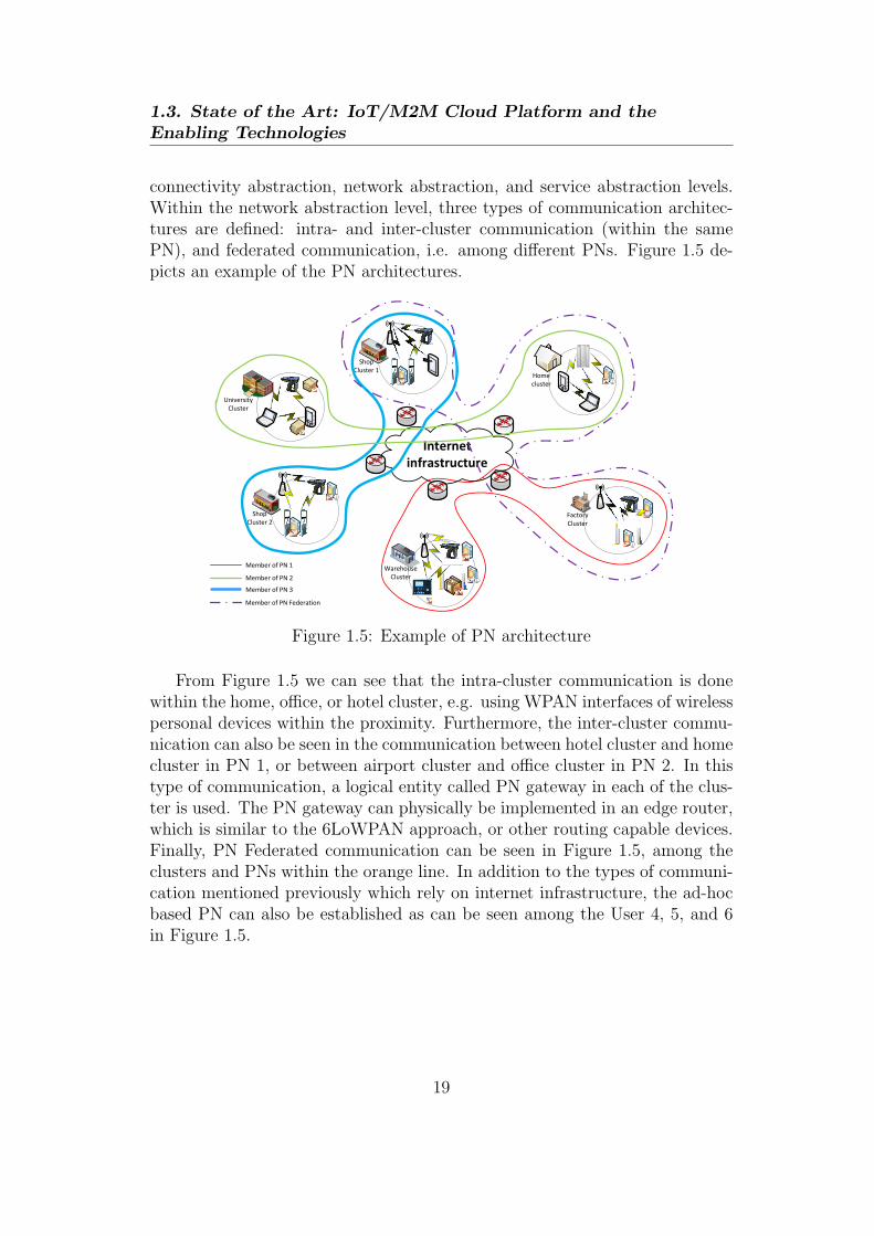
connectivity abstraction, network abstraction, and service abstraction levels.Within the network abstraction level, three types of communication architec-tures are defined: intra- and inter-cluster communication (within the samePN), and federated communication, i.e. among different PNs. Figure 1.5 de-picts an example of the PN architectures.
Warehouse
Cluster
Factory
Cluster
Shop
Cluster 1
Shop
Cluster 2
Home
cluster
University
Cluster
Internet
infrastructure
Member of PN 2
Member of PN 3
Member of PN 1
Member of PN Federation
Figure 1.5: Example of PN architecture
From Figure 1.5 we can see that the intra-cluster communication is donewithin the home, office, or hotel cluster, e.g. using WPAN interfaces of wirelesspersonal devices within the proximity. Furthermore, the inter-cluster commu-nication can also be seen in the communication between hotel cluster and homecluster in PN 1, or between airport cluster and office cluster in PN 2. In thistype of communication, a logical entity called PN gateway in each of the clus-ter is used. The PN gateway can physically be implemented in an edge router,which is similar to the 6LoWPAN approach, or other routing capable devices.Finally, PN Federated communication can be seen in Figure 1.5, among theclusters and PNs within the orange line. In addition to the types of communi-cation mentioned previously which rely on internet infrastructure, the ad-hocbased PN can also be established as can be seen among the User 4, 5, and 6in Figure 1.5.
19

Chapter 1
1.3.4 IoT/M2M Cloud Platforms
1.3.4.1 Cloud Computing Paradigm
Cloud computing has rapidly grown a huge attention in recent years due to itsgreat flexibility, scalability, and availability in obtaining computing resourcesat lower cost [32]. As cloud computing is an emerging form of distributed com-puting that is still undergoing evolution and standardization, the term itselfis often used with different meanings and interpretations [32]. Nevertheless,cloud computing system has some important characteristics and paradigmswhich lead to a general taxonomy that describes different aspects of it.
1.3.4.1.1 Users and providers relationship The users and providersrelationship in cloud computing is more complicated than that in general webservices, consisting of three roles, i.e. Cloud System provider, Cloud ServiceProvider, and Service Consumer, as depicted in Figure 1.6 [64]. The CloudService Consumer is an individual or organization that consume the CloudComputing service provided by Cloud Service Provider. The Cloud ServiceProvider is the organization that offers the Cloud Computing service, whomis also a user of Cloud Computing system. The Cloud System Provider is theorganization that offers the Cloud Computing system or infrastructure, whichmay be a corporate business, non-profit organization, or government agency.In this type of relationship, it is important to note that Cloud Service Provideracts as third party that maintains information about, or on behalf of, anotherentity [64].
Cloud System
Provider
Cloud Service
Provider
Cloud Service
Consumer
Web service/application
Utility computing
Figure 1.6: Users and providers relationships in cloud computing
1.3.4.1.2 Essential characteristics Five essential characteristics of cloudservices that demonstrate their relation to, and differences from, traditionalcomputing approaches are as follows [17]:
20

1.3. State of the Art: IoT/M2M Cloud Platform and theEnabling Technologies
• On-demand self-service. A consumer can unilaterally provision com-puting capabilities such as server time and network storage as needed au-tomatically, without requiring human interaction with a service provider.
• Broad network access. Capabilities are available over the networkand accessed through standard mechanisms that promote use by hetero-geneous thin or thick client platforms (e.g., mobile phones, laptops, andPDAs) as well as other traditional or cloud based software services.
• Resource pooling. The provider’s computing resources are pooled toserve multiple consumers using a multi-tenant model, with different phys-ical and virtual resources dynamically assigned and reassigned accordingto consumer demand. There is a degree of location independence in thatthe customer generally has no control or knowledge over the exact lo-cation of the provided resources, but may be able to specify location ata higher level of abstraction (e.g., country, state, or data center). Ex-amples of resources include storage, processing, memory, network band-width, and virtual machines. Even private clouds tend to pool resourcesbetween different parts of the same organization.
• Rapid elasticity. Capabilities can be rapidly and elastically provisioned— in some cases automatically — to quickly scale out; and rapidly re-leased to quickly scale in. To the consumer, the capabilities available forprovisioning often appear to be unlimited and can be purchased in anyquantity at any time.
• Measured service. Cloud systems automatically control and optimizeresource usage by leveraging a metering capability at some level of ab-straction appropriate to the type of service (e.g., storage, processing,bandwidth, or active user accounts). Resource usage can be monitored,controlled, and reported — providing transparency for both the providerand consumer of the service.
1.3.4.1.3 Cloud deployment models
• Private cloud: Data and processes are managed within the organizationwithout the restrictions of network bandwidth, security exposures andlegal requirements that using public cloud services across open, publicnetworks might entail.
21
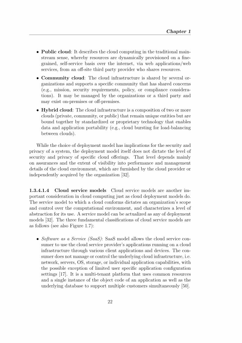
Chapter 1
• Public cloud: It describes the cloud computing in the traditional main-stream sense, whereby resources are dynamically provisioned on a fine-grained, self-service basis over the internet, via web applications/webservices, from an off-site third party provider who shares resources.
• Community cloud: The cloud infrastructure is shared by several or-ganizations and supports a specific community that has shared concerns(e.g., mission, security requirements, policy, or compliance considera-tions). It may be managed by the organizations or a third party andmay exist on-premises or off-premises.
• Hybrid cloud: The cloud infrastructure is a composition of two or moreclouds (private, community, or public) that remain unique entities but arebound together by standardized or proprietary technology that enablesdata and application portability (e.g., cloud bursting for load-balancingbetween clouds).
While the choice of deployment model has implications for the security andprivacy of a system, the deployment model itself does not dictate the level ofsecurity and privacy of specific cloud offerings. That level depends mainlyon assurances and the extent of visibility into performance and managementdetails of the cloud environment, which are furnished by the cloud provider orindependently acquired by the organization [32].
1.3.4.1.4 Cloud service models Cloud service models are another im-portant consideration in cloud computing just as cloud deployment models do.The service model to which a cloud conforms dictates an organization’s scopeand control over the computational environment, and characterizes a level ofabstraction for its use. A service model can be actualized as any of deploymentmodels [32]. The three fundamental classifications of cloud service models areas follows (see also Figure 1.7):
• Software as a Service (SaaS): SaaS model allows the cloud service con-sumer to use the cloud service provider’s applications running on a cloudinfrastructure through various client applications and devices. The con-sumer does not manage or control the underlying cloud infrastructure, i.e.network, servers, OS, storage, or individual application capabilities, withthe possible exception of limited user specific application configurationsettings [17]. It is a multi-tenant platform that uses common resourcesand a single instance of the object code of an application as well as theunderlying database to support multiple customers simultaneously [50].
22
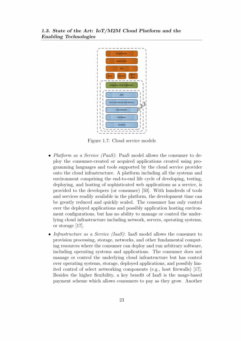
1.3. State of the Art: IoT/M2M Cloud Platform and theEnabling Technologies
Facilities
Hardware
Virtualization
Core connectivity and delivery
APIs
Integration OS & middleware
Data ContentMeta-
data
APIs
Applications
Presentation
IaaS PaaS
SaaS
Figure 1.7: Cloud service models
• Platform as a Service (PaaS): PaaS model allows the consumer to de-ploy the consumer-created or acquired applications created using pro-gramming languages and tools supported by the cloud service provideronto the cloud infrastructure. A platform including all the systems andenvironment comprising the end-to-end life cycle of developing, testing,deploying, and hosting of sophisticated web applications as a service, isprovided to the developers (or consumer) [50]. With hundreds of toolsand services readily available in the platform, the development time canbe greatly reduced and quickly scaled. The consumer has only controlover the deployed applications and possibly application hosting environ-ment configurations, but has no ability to manage or control the under-lying cloud infrastructure including network, servers, operating systems,or storage [17].
• Infrastructure as a Service (IaaS): IaaS model allows the consumer toprovision processing, storage, networks, and other fundamental comput-ing resources where the consumer can deploy and run arbitrary software,including operating systems and applications. The consumer does notmanage or control the underlying cloud infrastructure but has controlover operating systems, storage, deployed applications, and possibly lim-ited control of select networking components (e.g., host firewalls) [17].Besides the higher flexibility, a key benefit of IaaS is the usage-basedpayment scheme which allows consumers to pay as they grow. Another
23

Chapter 1
important advantage is that by always using the latest technology, cus-tomers can achieve a much faster service delivery and time to market[50].
1.3.4.2 Existing IoT/M2M Cloud Platforms
There are numbers of IoT/M2M Cloud Platforms offered by companies as theircommercial product or service. Some examples are Axeda M2M Cloud Service[10], Xively [63], Libelium [38], etc. Research projects that aims particularlyat developing a IoT/M2M Cloud platform and solving some research problemsat the same time, e.g. reliability, scalability, security, etc, are also present.One example of such research project is Building the Environment for Thingas a Service (BETaaS) project [12]. In what follows, some overview of theexisting IoT/M2M Cloud platforms from Xively will be briefly presented inthis subsection.
Xively is a PaaS that provides the tools and services needed by developersto connect sensor data (e.g. energy and environment monitoring of a building,object, etc) to a public cloud and to create compelling applications based onthat data. Figure 1.8 shows a basic overview of Xively Cloud Services [63].
As illustrated in Figure 1.8, Xively Cloud Services provide messaging,data archiving, device provisioning, and directory services which are acces-sible through the Xively Application Programming Interface (API). Xively’sweb applications leverage the API to provide connected product lifecycle man-agement capabilities through Xively Developer Workbench and Xively Man-agement Console [63]. At the bottom layer, the Xively API provides interfacesto connected objects (e.g. sensors and hardware platforms), applications (e.g.web and native), and customer backend services (e.g. Customer RelationshipManagement (CRM)), in accessing Xively Cloud Services that is based onRESTful services, through different protocols, such as HTTP/HTTPS, sock-et/websocket, and Message Queuing Telemetry Transport (MQTT). On topof that, various libraries are provided as Open Source to allow painless in-tegration between different programming languages or device platforms andthe Xively API. Currently, the supported libraries are as follows: Android, C,Objective-C, Java, Java Script, PHP, Python, Ruby, Arduino, ARM mbed,and Electric Imp.
24
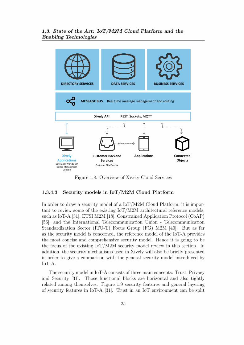
1.3. State of the Art: IoT/M2M Cloud Platform and theEnabling Technologies
DIRECTORY SERVICES DATA SERVICES BUSINESS SERVICES
MESSAGE BUS Real time message management and routing
Xively API REST, Sockets, MQTT
Xively
ApplicationsDeveloper Workbench
Device Management
Console
Customer Backend
Services
Customer CRM Service
Applications Connected
Objects
Figure 1.8: Overview of Xively Cloud Services
1.3.4.3 Security models in IoT/M2M Cloud Platform
In order to draw a security model of a IoT/M2M Cloud Platform, it is impor-tant to review some of the existing IoT/M2M architectural reference models,such as IoT-A [31], ETSI M2M [18], Constrained Application Protocol (CoAP)[56], and the International Telecommunication Union - TelecommunicationStandardization Sector (ITU-T) Focus Group (FG) M2M [40]. But as faras the security model is concerned, the reference model of the IoT-A providesthe most concise and comprehensive security model. Hence it is going to bethe focus of the existing IoT/M2M security model review in this section. Inaddition, the security mechanisms used in Xively will also be briefly presentedin order to give a comparison with the general security model introduced byIoT-A.
The security model in IoT-A consists of three main concepts: Trust, Privacyand Security [31]. Those functional blocks are horizontal and also tightlyrelated among themselves. Figure 1.9 security features and general layeringof security features in IoT-A [31]. Trust in an IoT environment can be split
25

Chapter 1
into two layers: networking and application. Networking trust is related tothe integrity of the routing process while application trust is more relatedto information quality, such as endpoint authentication and non-repudiation;confidentiality; privacy policy. Privacy is associated with the capability of aperson to protect their information, moreover by a legal perspective laws canput restrictions and obligations on the way information concerning users isstored and used. Security is a general concept that incorporates also Trustand Privacy [31].
IoT/VE Service
Access
Resolution
Service
Authorization Identity Management Trust and Reputation
Authentication
Channel Security
Key Exchange
and Mgmt.
Network Entry Network Management
Deployment Security
Se
rvice S
ecu
rity
Co
mm
un
icatio
n
Se
curity
Figure 1.9: IoT-A security features
To accomplish those concepts, the information model should include de-scriptions of access policies, certificates and trusted identities. Moreover thefunctional architecture should include components responsible for the manage-ment of trust, security and privacy.
The definition of the model for communication security adopts the distinc-tion between constrained and unconstrained networks from the communicationmodel. In fact, the heterogenity of devices represents a problem in designinga security model. To overcome this issue the security model has a high levelof abstraction. Gateways, being at the edge between networks of the differ-ent network types, are identified as central components for mediating betweendifferent security components of different networks. This includes tunnelling,filtering, and, most importantly, scaling down security (and other) functional-ities from unconstrained networks in order to meet the limitations imposed bythe constrained networks [44].
In Xively, the platform and web tools run on LogMeIn’s proprietary securecloud infrastructure [39], to ensure the service and client’s data is protected,
26

1.3. State of the Art: IoT/M2M Cloud Platform and theEnabling Technologies
available, and fault-tolerant. Several security aspects emphasized in Xively,especially for the developers, will be briefly described as follows [62]:
1. API keys: The Xively API uses API Keys to authenticate requestsand to control access to all API resources. An API key is a hierarchyof three objects: key object, permissions object, and resource object.A key object is the main object of an API key. This key object mustconsist of at least a permissions object which represents a different setof permissions, while it is optional to have one or more resource objectwithin a permissions object. A fine-grained access control can be realizedby the API keys by configuring value of the permission object accordingto the developer’s needs. Thus, the access to a resource can be grantedon an as-needed, when-needed basis, and take it away when it’s not.
2. OAuth: OAuth [46] is a method for allowing third-party applicationaccess to a resource owner’s resources without giving them access to re-source owner’s username and password. The Xively implementation ofOAuth 2.0 currently gives the third party site an API key which can ac-cess resource owner whole account with configurable permissions. UsingOAuth in Xively is excellent for tying in administrative applications andservices, such as an application that is used by a company to monitorall of its customers electricity usage and integrate it with an existingmanagement system, e.g. CRM. It is also good for an application inwhich the users interact in a collaborative manner. However, it is notrecommended for applications in which the end users can interact withtheir device because OAuth will give permission or authority to users toaccess any feed or information under the account’s owner.
3. Secure provisioning: A device is provisioned with a Feed ID and APIKey upon its first Activation call to the Xively API. The flexible acti-vation processing infrastructure with secure and encrypted device provi-sioning allows the user to automate what happens when the user’s deviceswake up for the first time. This allows calibration of secure connectionis established, credentials are exchanged, and devices, applications andservices into user’s circle of trust.
27
Chapter 1
1.4 Challenges of the IoT/M2M System
1.4.1 Security and Privacy
1.4.1.1 The number of vulnerable systems
The number of vulnerable systems and attacks vectors will surely increase inthe context of the IoT, thus fault tolerance becomes essential. Not only wemust strive for security by default (robust implementations, usable systems,etc.) in the IoT, but also we need to develop awareness mechanisms thatcan be used to create the foundations of intrusion detection and preventionmechanisms, which will help IoT entities to protect or even gracefully degradetheir services [51].
1.4.1.2 Access Control
Rolf H. Weber brings up the new security and privacy challenges in [59] inwhich he points out that the technical architecture of IoT has an impact onthe security and privacy of the involved stakeholder. Among others, one ofthe security and privacy requirements mentioned in [59] is the Access Control,which necessitates that the information providers must be able to implementaccess control on the data provided. Further on, [59] also mentions how theaccess control has to be implemented in the presence of Peer-to-Peer (P2P)system or Distributed Hash Table (DHT) which can be employed to increasethe security and privacy.
The authors of [9] also discuss the security and privacy challenges of theIoT quite extensively. Apart from the types of security threats imposed to theIoT, such as physical and eavesdropping, as well as the major security concernon the authentication and data integrity whose solutions are mostly based oncryptographic methods, privacy is another major issue that can be looked andsolved based on different approaches. One of the approach in dealing with theprivacy issue is to ensure that the personal data collected by the IoT system isused only to support the authorized services by authorized providers [9], whichessentially suggests the proper usage of access control system.
From the cloud computing side, NIST published a set of guidelines to ensurethe security and privacy especially for the public cloud deployment in [32]. Insummary, the key security and privacy issues in cloud computing are as follows:governance, compliance, trust, architecture, identity and access management,software isolation, data protection, availability, and incident response. Again,
28
1.4. Challenges of the IoT/M2M System
access control – which comes under identity and access management – is listedamong the key issues to be taken care of also in the cloud computing. It isimportant to note that, the security and privacy risks in the cloud computingservices vary significantly among organizations, depending on the intendedpurpose, assets held, legal obligations, and so on [32]. Therefore, the securityand privacy objectives of each organization is the key factor in determiningthe appropriate mechanisms for securing their cloud services. In the context ofaccess control, it is necessary to have a flexible access policy framework thatcan cope with this challenge, i.e. compatible with various security and privacyobjectives of different organizations.
Last but not least, the authors of [51], and [20] in particular, highlightthe importance of resource and information protection, i.e. access control, indistributed systems such as the IoT. With this, we can safely conclude thatthe Access Control is one of the important security and privacy concerns inIoT/M2M while its actual model and implementation in the IoT/M2M systemsis often overlooked and remains as an open issue. Unique characteristics of theIoT/M2M system and architecture signify particular challenges in the accesscontrol of such system. These issues will be further discussed in Section 1.4.2.
1.4.2 Distributed architecture
As have been discussed earlier, the vision of IoT/M2M to connect billions andeven trillions of devices over the internet will eventually make the commu-nication topology or architecture be more and more distributed. Althoughthe early adopted approach of IoT/M2M is the centralized approach, the dis-tributed architecture approach of IoT/M2M is a necessity in order to takefull advantage of it. Rodrigo Roman et al. in [51] analyse the features andsome specific security and privacy challenges of distributed IoT. In summary,[51] specify some challenges and considerations specific to access control of thedistributed IoT, such as scalability and consistency, granularity, constraineddevices, context, and delegation mechanisms.
1.4.2.1 Scalability
The scalability and consistency issues will arise when storing the list of usersand their associated access rights in Access Control List (ACL)s [51] due to thehuge numbers of nodes and users interacting to each other in the IoT/M2Msystem. Employing an existing access control mechanism, e.g. the Role BasedAccess Control (RBAC), is not straight forward as it needs to define roles that
29

Chapter 1
users can take, which might be different in various contexts even though theyrefer to the same type of entity [51]. Indeed, the Identity-based access control,such as RBAC, have been found to be inflexible, don’t scale well, and aredifficult and to upgrade [33]. Hence, designing an access control mechanismthat can cope with the scalability challenge a distributed environment suchas IoT/M2M is of upmost important, which is not as trivial as applying theexisting access control mechanisms.
1.4.2.2 Context
IoT is closely connected to its context [11]. The context or contextual informa-tion includes environment context (e.g. sensing data), temporal context (e.g.time and location), user context, system context, and some specific businesscontext (e.g. information about business step, business transaction type, etc,in RFID middleware). However the context is inherently dynamic in naturewhich will influence the access policy decision [11]. It is also reported in [21]that one of the requirements of the access control solution for IoT is to be flex-ible to adapt to different contexts. In fact, the IoT/M2M is the dynamic nodesconnectivity and network topologies due to the mobility and other factors suchas power constraint. Therefore designing a flexible access control system thatcan cope with the dynamic nature of IoT/M2M and contextual information isone of the challenging tasks.
1.4.2.3 Delegation
Another characteristic of a distributed or decentralized system is the decisionmaking can be delegated from the higher authorities to the lower level enti-ties. In a totally distributed topology, i.e. without hierarchy, the authoritydelegation can be performed among the entities. As earlier mentioned, thedynamic nature of IoT/M2M is an inherent challenge in such a system, hencethe authority delegation is another way of coping with this characteristic. Forexample, a node may delegate its authority to the other nodes before it diesout, e.g. out of battery. The challenge for access control in IoT/M2M in thisregard is how to design a dynamic and efficient authority delegation which isable to keep the delegation process under control, e.g. not delegating accessjust to any entity.
30

1.5. Problem statement and research questions
1.4.2.4 Granularity
The authors of [51] also indicate the importance of granularity (i.e. provid-ing more information to people with the right credentials) and location (i.e.whether users are accessing the thing services locally or remotely) for the ac-cess control policies in certain scenarios. But actually it should be generalizedthat not only the location, but the context along with granularity are two im-portant elements for the access control policies in IoT/M2M, as the contextthat are attached to the users and resources being accessed will determine thegranularity level of the information to be disclosed to the users. The real chal-lenge in this aspect is how to design a fined-grained access control policy withthe help of contextual information to deal with large amounts of information,including the measurements data and events, generated by IoT/M2M nodes.
1.5 Problem statement and research questions
As the attempt to answer the challenges explained in Section 1.4, the researchproblems addressed in this PhD dissertation is on the design of a scalable,flexible, and fine-grained access control mechanism for the IoT/M2M Cloudplatform by making use of distributed approaches for resource constraint net-works such as RFID and wireless sensor network. The problem statement isdivided into different sub-problems as follows:
• Management and security access control in IoT/M2M middleware
• Access control and authority delegation in federated IoT environment
• Intrussion detection system in the access control for the IoT/M2M Cloudplatform
The previously defined problem statement leads to the following researchquestions:
• How to provide a fine-grained, efficient policy assignment, and interop-erable access control in IoT/M2M middleware, particularly the RFIDmiddleware?
• How to support the efficient and scalable mobility management coupledwith the access control in the IoT/M2M middleware?
31

Chapter 1
• How to overcome the scalability and dynamic nature of the IoT/M2M is-sues, and to provide a certain level of authentication in the access controlmodel?
• How to model the intrusion detection system incorporated with accesscontrol system for the IoT/M2M Cloud platform, where there exist a setof security assets to be protected, the uncertainty on the maliciousnessof the opponent, and some resource constraint?
1.6 Hypotheses and research methodology
1.6.1 Hypotheses
The research questions regarding the access control in the IoT/M2M Cloudplatform as described previously in Section 1.5 lead to several hypotheses de-scribed as follows:
1.6.1.1 Fine-grained access control
An access policy design that incorporates access rule evaluation that consistsof specific RFID events attributes and conditions as well as the user profilesand trust can fulfil the requirements of fine-grained and efficient access policyassignment in the access control model for the inter-enterprise RFID system,i.e. RFID middleware. In addition, a web service based implementation ofthe access control system allows interoperability with the overall RFID mid-dleware.
1.6.1.2 Efficient mobility management and access control
An architectural approach is needed in order to integrate the RFID systemto the global IP network and providing an efficient mobility management atthe same time. Moreover, it can also de-couple the access control systemin order to make it more scalable. For such reasons, a hypotheses is madethat a SIP-based location management system in the RFID middleware canprovide seamless integration between RFID system to the global IP network,and efficient mobility management and access control.
32
1.6. Hypotheses and research methodology
1.6.1.3 Capability-based and context aware access control
The scalability issue in the IoT/M2M networks which consists of huge numbersof devices or “things” is addressed by using a capability-based access controlas it relies on a capability (also known as a “ticket”) owns by each entity ina distributed manner. Including some context information and a delegationframework in the access control model will help the system to make a moreprecise access decision and provide flexibility against the dynamic nature of theIoT/M2M, e.g. dynamic context and connectivity due to mobility and powerconstraint. Based upon these arguments, the following hypotheses is made: thecapability-based and context aware access control with a delegation frameworkwill be able to overcome the scalability issue and the dynamic nature of theIoT/M2M. As a capability comprises a token that needs to be validated priorto granting an access, another hypotheses is made that the capability-basedand context aware access control can also provide some level of authentication.
1.6.1.4 Intrussion detection in the access control system
An intrusion detection system is needed to be part of the access control sys-tem to detect and mitigate the threats, especially those that come from theinsiders of an M2M local cloud platform. The interaction between an attackerand a defender equipped with intrusion detection can be modelled by the gametheory. It is further argued that the uncertainties that exists about the mali-ciousness of the opponent can be modelled with a multi-stage Bayesian gamewhich include an analytical model of a set of assets with different values to beprotected by the defender and the resource constraint of each player.
1.6.2 Methodology
The high level overview of the research approach in this PhD work starts withidentifying the root cause of the problems, followed by creating a high levelmodel that bridges the problems and solution, then the proposed solutions aredesigned (e.g. complete design of protocol, software architecture, and mathe-matical model), verified (e.g. by means of computer simulation, software de-velopment and experiments), and analysed. The method used in this researchis mainly the quantitative research method.
To carry out the quantitative research method, the data is collected throughsome computer simulations and experiments. The simulation tools used tocarry out the computer simulation include MATLAB and AVISPA (a validation
33
Chapter 1
tool of internet security protocol and application) that are widely accepted bythe scientific community, and the detailed simulation procedure is explainedlater in the respective chapter. The experiment activities in the context of thisPhD research work is carried out to follow up the software implementationof the proposed solutions, which results in a collection of measured data forfurther analysis. As a result, the qualitative analysis is performed based onthe simulated and measured collected data, which is explained in more detaillater in each of the respective chapter.
1.7 Research goals and scope
The background and motivation of the IoT/M2M and cloud computing systemsas well as the security and privacy challenges therein that have been outlined sofar in this dissertation lead to many interesting research questions and subjectsof study. However, given the limitation of time and resources that constitute aPhD study, the scope of this dissertation is confined to investigating a numberof security and privacy issues for a specific IoT/M2M technology and cloudcomputing model. In this section, we present the research goals as well asthe scope and limitations of the work, and the rationale behind the delimitingchoices.
1.7.1 Research goals
Based on the challenges and hypothesis stated earlier in Section 1.4 and 1.6,the goals of this PhD research are defined as follows:
1. Design and implementation of fine-grained access control in the scope ofRFID middleware.
2. Design and implementation of a mobility management in RFID middle-ware that supports the access control mechanism.
3. Desgin and implementation of scalable access control with a flexible ac-cess delegation for the IoT/M2M Cloud platform.
4. Analysis and design of an intrusion detection in the access control systemfor the IoT/M2M Cloud platform.
5. Test bed implementation for proof of concepts towards real system real-ization of the research works.
34
1.7. Research goals and scope
1.7.2 Scope of the research
Most of the security and privacy issues that are researched and presented inthis dissertation are related to the access control. This PhD study is part ofseveral European Commission funded projects, such as My Adaptive GlobalNETwork (MAGNET), Advance Sensors and Programmable middleware forInnovative Rfid Enterprise applications (ASPIRE), Intelligent System for In-dependent living and SElfcare of seniors with cognitive problems or Mild De-mentia (ISISEMD), and BETaaS, where security and privacy requirementsare mostly focussed around the access policies among different types of usersinto the platform, middleware, or devices. With this background in mind, thefocus of this PhD work was limited to access control mechanism among thestakeholders of the respective projects into the IoT/M2M and Cloud platform,regardless of any method applied to authenticate the user or entity. Moreover,the IoT/M2M is highly distributed and dynamic in nature. Such requirementshave motivated us to focus the large part of our research on designing a scalableaccess control model with access delegation in multi-domain or federated envi-ronment; and also designing of a scalable IoT/M2M Cloud platform, includingthe middleware, in which such access control model are to be applied.
The target platform in terms of the identification, sensing, and communica-tion technology in this PhD study is limited to the RFID and sensor technology.The maturity and advance development of RFID technology towards realizingthe vision of IoT – besides the fact that part of this PhD study is done underthe scope ASPIRE project where RFID becomes the central point of interest– have become our strong motivation to limit our focus in this regard. Havingthis decision in mind, the investigation of the middleware for IoT/M2M systemin the scope of this PhD study is limited to RFID middleware which has beenbriefly introduced in Section 1.3.2.
The type of services offered by most of the existing IoT/M2M cloud serviceproviders are generally either a Software as a Service (SaaS) or a Platformas a Service (PaaS) models. In this regard, we include a new type of cloudservice model known as Things as a Service (TaaS), which contains a unifiedrepresentation of an M2M model and enables any high level IoT/M2M serviceto be built. This is a concept that is introduced in BETaaS project, which alsointroduces another concept of cloud model where a set of distributed IoT/M2Mgateways are able to form cloud locally. As pointed out earlier, a scalableaccess control that supports flexible access delegation is also a necessity insuch a distributed local cloud scenario. Furthermore, an intrusion detectionsystem needs to be part of the access control system to enable the monitoringof important resources, and to detect of any malicious behaviour. In this
35
Chapter 1
study, the malicious behaviour monitoring is focused to that which is comingfrom within the local cloud, i.e. the insider, because it is a great securitythreat to the IT systems and network in general. Therefore, the study ofdynamic interaction between malicious and regular gateway which has a setof accessible resources or security assets, under some constraint in terms ofattack and monitor resources, is presented in this dissertation.
An idea remains an abstract concept unless it is implemented in a real sys-tem realization. Test beds and practical implementation of such an IoT/M2MCloud platform along with the security access control mechanism is a necessarystep in a life cycle of any novel research, i.e. to proof the proposed conceptsand to take the ideas further into the real product. E-Health scenario is ourfirst focus in the test bed implementation within the scope of this PhD work.The huge potential of eHealth to answer the challenge of ageing population andto reduce the health treatment cost, yet lacking in maturity and real productsand services taking off in the market, have become our motivation to focus ourtest beds implementation in such area. The supply chain use case is anothertest bed implementation in this PhD work, which is motivated by the factthat the supply chain scenario is the main driver in the development of RFIDmiddleware.
1.8 Overview of the dissertation and scientific
contributions
An overview of the chapters and the scientific contributions that constitutethis PhD dissertation are summarily discussed below.
In chapter 2, a proposed access control model designed to deal with a verylarge and highly dynamic inter-enterprise RFID data is presented, along withsystem implementation and evaluation. The key contributions of the proposedaccess control model are as follows. First, a dynamic and efficient access policymechanism of an object or group of objects, based on the EPCglobal compliantattributes and vocabularies is introduced. This access policy takes the profileof the accessing entity (i.e. individual or organization that requests to accessRFID events information), and results in a suitable set of access rules of thecorresponding entity to the object(s). This way, the access policy can bedynamically reuse for any user that even had no relationship before. Second,fine grained policy access enforcement method to handle large amounts ofRFID events information, using the created rules and contextual information,is presented. For evaluation purpose, a the proposed access control model
36

1.8. Overview of the dissertation and scientific contributions
implementation with the spirit of inter-operability is developed and tested.This chapter fulfills the research goals number 1 and 5 which are stated inSection 1.7.1. The scientific contribution that constructs this chapter and ispublished in [6] as a journal publication.
Chapter 3 highlights our contributions in the open IoT/M2M middlewareplatform, along with our proposed secure access control mechanism. In thisregard, both the architectural design of RFID middleware and secure accesscontrol approaches are employed to tackle the tag mobility and security issues.First, an architecture based on Session Initiation Protocol (SIP) signallingis proposed for the location and mobility management in the inter-enterpriseRFID middleware sub-system. The proposed architecture is shown to greatlyreduced the delay and is easily scale to many number of tags as compared withthe existing system used as our reference point. Second, the access controlmechanism, as one way to control the RFID events information to be accessedby other parties, is shown to integrate well with this approach. From thearchitectural point of view, performing access control at the SIP gateway is abetter approach than at the EPCIS server because SIP gateway is the first entrypoint before the information stored at the EPCIS repository is accessed. Thischapter fulfills the research goals number 2 and 5 which are stated in Section1.7.1. The scientific contributions that constitute this chapter are publishedin several conference publications [2, 4]. Other contributions in the scope ofASPIRE project deliverables are also published [58, 57].
In Chapter 4, a secure access control model with authority delegation mech-anism based on capability and contextual information is investigated and de-signed for IoT/M2M system. The key contributions of the proposed accesscontrol model are as follows. First, the scalability challenge in a highly dis-tributed IoT/M2M system is addressed by introducing capability with identityof the Subject, i.e. an entity that request for an access of a certain resource.Secondly, the dynamic nature of IoT/M2M system that require a flexibility inaccess decision is tackled by incorporating contextual information in the accesspolicies, access delegation by means of capability propagation, and introduc-ing a virtual identity that is linked with a certain profile which can be flexiblydefined by the user or device owner. Moreover, the privacy issue in accesscontrol is overcome by the virtual identity that is also linked with access poli-cies. Third, the proposed access control model is shown to be secure againstman-in-the-middle and replay attacks and able to achieve the authenticationby introducing a nonce and some lightweight cryptographic operation. Thischapter fulfills the research goals number 3 as stated in Section 1.7.1. Themajor scientific contributions that constitute this chapter are published in aconference publication [3] and a book chapter [5]. Other minor contributions
37

Chapter 1
related to this chapter are also published in conference publication [42, 41].An identity establishment and authentication method based on Elliptic CurveCryptography (ECC) that complement the proposed access control model ispresented in [42] and practical implementation along with the performanceand security evaluation of the identity driven capability-based access controlis demonstrated in [41].
Chapter 5 presents a practical implementation and use cases of a capabil-ity based access control for the IoT/M2M local cloud platform. The proposedcapability access control in this chapter is aimed at solving the inherent is-sues, such as scalability and enforcing least privilege access principle, of theexisting access controls, e.g. ACL, Role Based Access Control (RBAC) [53],and Attribute Based Access Control (ABAC) (e.g. Extensible Access ControlMarkup Language (XACML) [61]), by using capability. It also solves the accessdelegation issue in the existing IoT/M2M cloud platform that relies on APIkey and OAuth [46] for the access delgation, in which the OAuth application,i.e. the 3rd party application, is able to access all the resources tied with thedelegating party under a specific access permission, e.g. Read, Write or Delete,by indicating a specific set of resource that can be accessed in the delegation.The issue of controling the delegation chain through capability propagation isalso addressed by using a validation method based on a Public Key Infrastruc-ture (PKI). In addition, the aforementioned validation method also improvesthe access delegation mechanism of the Capability-based Context-Aware Ac-cess Control (CCAAC) model in chapter 4, i.e. to make it more flexible and yetkeeping the access delegation under control. Several uses cases show that theproposed capability based access control is suitable to the various operations ofthe IoT/M2M cloud platform. But in principal, it is also suitable for any kindof cloud computing platform. This chapter fulfills the research goals number3 and partly 5 which are stated in Section 1.7.1. The scientific contributionthat constitute this chapter is published in a conference publication [8].
In chapter 6, an analytical framework of an intrusion detection in accesscontrol system based on game theoretic approach is presented. Similar tochapter 5, the target platform being investigated in this study is the IoT/M2Mlocal cloud platform which consists of a collection of distributed IoT/M2Mgateways. Here, each gateway has a set of resources or assets with differentsecurity values whom the access is governed by the access control system that isintegrated with an Intrusion Detection System (IDS). To model such system,a two-player multi-stage Bayesian game is proposed. The two players areattacker and defender, each of them has a constraint in terms of attack andmonitor resource respectively. The Bayesian game is chosen due to some degreeof uncertainties in the IDS and naturally the defender does not know whether
38
1.8. Overview of the dissertation and scientific contributions
or not the attacker is malicious. The multi-stage type of game means thegame is played repeatedly and the previous actions may influence the currentdecision, consequently the player, e.g. defender, needs to update its belief ineach stage of the game and this is done by Bayes rule. Based on the proposedanalytical framework, the set of Perfect Bayesian Equilibrium (PBE) strategiesfor both players in each stage game is formulated, and the framework is alsoanalysed numerically in order to validate the proposed analytical framework.This chapter fulfills the research goals number 4 as stated in Section 1.7.1. Thescientific contribution that constructs this chapter is published in a conferencepublication [7].
In chapter 7, the overall research work conclusions and future scope for theresearch work are contained. This ties up all the findings in our PhD studyand enlightens the path for forthcoming researchers in this field.
To summarize, all the thesis chapters are correlated with each other asdepicted in Figure 1.10.
39

Chapter 1
Access Control in IoT/M2M
Cloud Platform
Chapter 1
Introduction
Chapter 4
Capability-based And
Context Aware Access
Control for IoT
Chapter 2
Efficient and Fine-grained
access control for RFID
middleware
Chapter 3
Secure Open M2M-RFID
Middleware
Chapter 6
Intrusion detection in the
access control system for the
M2M Cloud platform
Chapter 5
Capability-based Access
Control for IoT/M2M Cloud
platform
Access Control in the
RFID Middleware System
Capability-based Access
Control system in IoT
Access Control in IoT/M2M
Local cloud platform
Figure 1.10: Correlation of dissertation chapters
40

1.9. References
1.9 References
[1] Julien Abeille, Mathilde Durvy, Jonathan Hui, and Stephen Dawson-Haggerty. Lightweight ipv6 stacks for smart objects: the experience ofthree independent and interoperable implementations. Internet Protocolfor Smart Objects (IPSO) Alliance, White Paper #2, November 2008.
[2] Bayu Anggorojati, Kamil Cetin, Albena Mihovska, and Neeli R. Prasad.Rfid added value sensing capabilities: European advances in integratedrfid-wsn middleware. In Sensor Mesh and Ad Hoc Communications andNetworks (SECON), 2010 7th Annual IEEE Communications SocietyConference on, June 2010.
[3] Bayu Anggorojati, Parikshit N. Mahalle, Neeli R. Prasad, and RamjeePrasad. Capability-based access control delegation model on the federatediot network. InWireless Personal Multimedia Communications (WPMC),2012 15th International Symposium on, September 2012.
[4] Bayu Anggorojati, Parikshit N. Mahalle, Neeli R. Prasad, and RamjeePrasad. Efficient and scalable location and mobility management of epc-global rfid system. In Wireless Personal Multimedia Communications(WPMC), 2013 16th International Symposium on, June 2013.
[5] Bayu Anggorojati, Parikshit N. Mahalle, Neeli R. Prasad, and RamjeePrasad. Secure access control and authority delegation based on capabilityand context awareness for federated iot. In Fabrice Theoleyre and Ai-Chun Pang, editors, Internet of Things and M2M Communications. RiverPublisher, 2013.
[6] Bayu Anggorojati, Neeli R. Prasad, and Ramjee Prasad. Efficient finegrained access control for rfid inter-enterprise system. Journal of CyberSecurity and Mobility, 2(3 & 4), 2013.
[7] Bayu Anggorojati, Neeli R. Prasad, and Ramjee Prasad. An intrusiondetection game in access control system for the m2m local cloud platform.In The 19th Asia Pasific Conference on Communications (APCC) 2013,August 2013.
[8] Bayu Anggorojati, Neeli R. Prasad, and Ramjee Prasad. Securecapability-based access control in the m2m local cloud platform. InWireless Communications, Vehicular Technology, Information Theoryand Aerospace & Electronic Systems Technology (Wireless VITAE), 2014IEEE 4th International Conference on, May 2014.
41

Chapter 1
[9] Luigi Atzori, Antonio Iera, and Giacomo Morabito. The internet of things:A survey. Computer Networks, 54(15):2787 – 2805, 2010.
[10] Axeda. M2m cloud service. http://www.axeda.com/platform.
[11] Guangdong Bai, Lin Yan, Liang Gu, Yao Guo, and Xiangqun Chen.Context-aware usage control for web of things. Security and Commu-nication Networks, 2012.
[12] BETaaS. Building the environment for the things as a service.http://www.betaas.eu.
[13] Hyuntae Cho, Jongdeok Kim, and Yunju Baek. Large-scale active rfid sys-tem utilizing zigbee networks. Consumer Electronics, IEEE Transactionson, 57(2):379 –385, may 2011.
[14] J.P. Conti. The internet of things. Communications Engineer, 4(6):20–25, dec.-jan. 2006.
[15] The National Intelligence Council. Disruptive civil technologies - six tech-nologies with potential impacts on us interests out to 2025. In ConferenceReport CR 2008-07, 2008.
[16] Adam Dunkels and JP Vasseur. Ip for smart objects. Internet Protocolfor Smart Objects (IPSO) Alliance, White Paper #1, September 2008.
[17] Glenn Brunette et al. Security guidance for critical areas of focus in cloudcomputing v2.1. Cloud Security Alliance, December 2009.
[18] ETSI. Machine-to-machine communications (m2m); functional architec-ture. Technical report, European Telecommunications Standards Institute(ETSI), 2011.
[19] Neil Gershenfeld, Raffi Krikorian, and Danny Cohen. The internet ofthings. Scientific American, 291(4):76 – 81, October 2004.
[20] S. Gusmeroli, S. Piccione, and D. Rotondi. Iot access control issues: Acapability based approach. In Innovative Mobile and Internet Services inUbiquitous Computing (IMIS), 2012 Sixth International Conference on,July 2012.
[21] S. Gusmeroli, S. Piccione, and D. Rotondi. A capability-based securityapproach to manage access control in the internet of things. Mathematicaland Computer Modelling, 58(5-6):1189 – 1205, 2013.
42
1.9. References
[22] http://wiki.aspire.ow2.org.
[23] Jonathan Hui, David Culler, and Samita Chakrabarti. 6lowpan: Incorpo-rating ieee 802.15.4 into the ip architecture. Internet Protocol for SmartObjects (IPSO) Alliance, White Paper #3, January 2009.
[24] Kai Hwang and Deyi Li. Trusted cloud computing with secure resourcesand data coloring. Internet Computing, IEEE, 14(5):14 –22, sept.-oct.2010.
[25] RFID in Japan. Battery-less sensor tags.http://ubiks.net/local/blog/jmt/archives3/005338.html.
[26] EPCglobal Inc. Epc information services (epcis) version 1.0.1 specifica-tion. September 2007.
[27] EPCglobal Inc. Epcglobal object name service (ons) version 1.0.1. May2008.
[28] EPCglobal Inc. The epcglobal architecture framework. December 2010.
[29] EPCglobal Inc. Gs1 epc tag data standard 1.6 - ratified standard. Septem-ber 2011.
[30] EPCglobal Inc. Gs1 epcglobal tag data translation (tdt) 1.6 - ratifiedstandard. October 2011.
[31] IoT-A. Internet of things - architecture. http://www.iot-a.eu.
[32] Wayne Jansen and Timothy Grance. Guidelines on security and privacyin public cloud computing. NIST Special Publication, December 2011.
[33] A.H. Karp. Authorization-based access control for the services orientedarchitecture. In Creating, Connecting and Collaborating through Comput-ing, 2006. C5 ’06. The Fourth International Conference on, 2006.
[34] Tom Karygiannis, Bernard Eydt, Greg Barber, Lynn Bunn, and TedPhillips. Guidelines for securing radio frequency identification (rfid) sys-tems - recommendations of the national institute of standards and tech-nology. NIST Special Publication, April 2007.
[35] Hermann Kopetz. Internet of things. In Real-Time Systems, Real-TimeSystems Series, pages 307–323. Springer US, 2011.
[36] K. Kumar and Yung-Hsiang Lu. Cloud computing for mobile users: Canoffloading computation save energy? Computer, 43(4):51 –56, april 2010.
43
Chapter 1
[37] G. Lawton. Machine-to-machine technology gears up for growth. Com-puter, 37(9):12 – 15, sept. 2004.
[38] Libelium. Wireless sensor network with waspmote and meshlium.http://www.libelium.com/development/waspmote/documentation, 2013.
[39] LogMeIn. Logmein - access, manage and support computers remotely.https://secure.logmein.com.
[40] ITU-T FG M2M. Deliverable d2.1 - m2m service layer: Requirements andarchitectural framework. Technical report, ITU-T, 2013.
[41] Parikshit N. Mahalle, Bayu Anggorojati, Neeli R. Prasad, and RamjeePrasad. Identity driven capability based access control (icac) scheme forthe internet of things. In 6th IEEE International Conference on AdvancedNetworks and Telecommunication Systems (ANTS) 2012, December 2012.
[42] Parikshit N. Mahalle, Bayu Anggorojati, Neeli R. Prasad, and RamjeePrasad. Identity establishment and capability based access control (iecac)scheme for internet of things. In Wireless Personal Multimedia Commu-nications (WPMC), 15th International Symposium on, September 2012.
[43] Friedemann Mattern and Christian Floerkemeier. From the internet ofcomputers to the internet of things. In From Active Data Management toEvent-Based Systems and More, volume 6462 of Lecture Notes in Com-puter Science, pages 242–259. Springer Berlin / Heidelberg, 2010.
[44] Enzo Mingozzi, Carlo Vallati, Giacomo Tanganelli, Giovanni Iovino, Va-lerio Di Gregorio, and Bayu Anggorojati. D1.4.1 - taas reference model.Technical report, BETaaS, 2012.
[45] Aikaterini Mitrokotsa and Christos Douligeris. Integrated rfid and sensornetworks: Architectures and applications. In RFID and Sensor Networks:Architectures, Protocols, Security, and Integrations, Wireless Networksand Mobile Communications, pages 511–535. CRC Press, November 2009.
[46] OAuth. Oauth 2.0. http://oauth.net.
[47] R. Prasad. My personal Adaptive Global NET (MAGNET). Signals andCommunication Technology Book. Springer Netherlands, 2010.
[48] Mirko Presser and Alexander Ghulak. The internet of things: Connect-ing the real world with the digital world. EURESCOM mess@ge - TheMagazine for Telecom Insiders, 2, september 2009.
44

1.9. References
[49] Intel WISP Project. http://seattle.intel-research.net/wisp/.
[50] B.P. Rimal, Eunmi Choi, and I. Lumb. A taxonomy and survey of cloudcomputing systems. In INC, IMS and IDC, 2009. NCM ’09. Fifth Inter-national Joint Conference on, aug. 2009.
[51] Rodrigo Roman, Jianying Zhou, and Javier Lopez. On the features andchallenges of security and privacy in distributed internet of things. Com-puter Networks, 57(10):2266 – 2279, 2013.
[52] Antonio G. Ruzzelli, Raja Jurdak, and Gregory M.P. O’Hare. the rfidwake-up impulse for multi-hop sensor networks. In 1st ACM Workshopon Convergence of RFID and Wireless Sensor Networks and their Appli-cations (SenseID) at the Fifth ACM Conference on Embedded NetworkedSensor Systems (ACM SenSys 2007), November 2007.
[53] R.S. Sandhu, E.J. Coyne, H.L. Feinstein, and C.E. Youman. Role-basedaccess control models. Computer, 29(2):38 –47, feb 1996.
[54] Sanjay Sarma, David L. Brock, and Kevin Ashton. The networked phys-ical world, proposals for engineering the next generation of computing,commerce & automatic-identification. MIT-AUTOIDWH-001, 2000.
[55] Zach Shelby and Carsten Bormann. 6LoWPAN: The Wireless EmbeddedInternet. Wiley Publishing, 2010.
[56] Zach Shelby, Klaus Hartke, Carsten Bormann, and Brian Frank. Con-strained application protocol (coap). Technical report, IETF, 2012.
[57] John Soldatos, Nikos Kefalakis, Nektarios Leontiadis, Bayu Anggorojati,Simone Frattasi, Neeli Prasad, Didier Donsez, Gabriel Pedraza, KievGama, and Jacky Estublier. D3.5: End-to-end infrastructure manage-ment. Technical report, ASPIRE, 2011.
[58] John Soldatos, Nikos Kefalakis, Nektarios Leontiadis, Nikolaos Konstanti-nou, Nathalie Mitton, Loc Schmidt, Roudy Dagher, Mathieu David, BayuAnggorojati, Simone Frattasi, Neeli Prasad, Didier Donsez, Gabriel Pe-draza, and Kiev Gama. D3.4b: Core aspire middleware infrastructure.Technical report, ASPIRE, 2010.
[59] Rolf H. Weber. Internet of things – new security and privacy challenges.Computer Law & Security Review, 26(1):23 – 30, 2010.
45

Chapter 1
[60] Geng Wu, S. Talwar, K. Johnsson, N. Himayat, and K.D. Johnson. M2m:From mobile to embedded internet. Communications Magazine, IEEE,49(4):36 –43, april 2011.
[61] XACML. https://www.oasis-open.org/standards#xacmlv2.0.
[62] Xively. Api docs - security.
[63] Xively. What is xively ? https://xively.com/whats xively.
[64] Minqi Zhou, Rong Zhang, Wei Xie, Weining Qian, and Aoying Zhou.Security and privacy in cloud computing: A survey. In Semantics Knowl-edge and Grid (SKG), 2010 Sixth International Conference on, November2010.
46
2Efficient Fine-Grained Access Controlfor RFID Inter-Enterprise Middleware
System
Access control management is a very challenging task in an inter-enterpriseRFID system due to huge amounts of information about things or objectsthat can be collected and accessed to and from the system. Furthermore, theinformation stored in the inter-enterprise RFID system contains sensitive andconfidential data related to the activities of the organization involved aroundthe RFID system. Hence, the efficiency and high-granularity are critical inthe design of access control for such system. This chapter presents a novelaccess control model which is efficient and fine grained for such a system. Adetail definition and mechanism of the access control model are described in thechapter. A system implementation is developed for the evaluation purpose. Animportant performance measure in big data processing is delay in processingtime, thus the evaluation aims at measuring the access control processing time.The evaluation results show that the model is consistent, and is able to achieveless delay than the inter-enterprise RFID system without access control at acertain point.
47

Chapter 2
2.1 Introduction
RFID technology allows the everyday things to be interconnected to the in-ternet world, thus the key component towards the full deployment of the IoTvision [2]. From the system components and architecture perspectives, RFIDsystem employed by any organization in its activity may consist of three sub-systems, namely RF, enterprise, and inter-enterprise sub-system [11]. Inter-enterprise sub-system in particular, is the most important component thatenables the objects or things visibility and tracking throughout their life cycle,i.e. in supply chain industry, etc. When the information about thousandsof things or objects is able to be gathered and accessed, consequently accesscontrol management of such information is a great challenge.
The technical specification, including the standard interfaces and data for-mat, that enables the inter-enterprise information sharing of RFID events datais specified in the EPCIS specification [8] issued by EPCglobal. The EPCISrepository, i.e. software implementation of this specification, in particular aimsat receiving application-agnostic RFID data, translate it into a correspondingbusiness events (e.g. business process, business location, event time, etc), andthen make the events available and accessible by upstream applications. Sincethe EPCIS repository potentially contains sensitive and confidential data ofany individual or organization, the access to such information through its in-terfaces needs to be managed properly. In this regard, it is important to men-tion that the access control mechanism in the EPCIS specification is left opento each specific implementation. Additionally, efficiency, fine level of granu-larity, and trust are important keys to the access control design since highlydynamic and huge amount of events data is expected to be generated by po-tentially thousands of tagged objects which are of any interest for individualsor organizations that have even had any relationship before.
There are two main contributions of this chapter. First, a dynamic andefficient access policy mechanism of an object or group of objects, based onthe attributes and vocabularies of EPCIS is introduced. This access policytakes the profile of the accessing entity (i.e. individual or organization thatrequests to access RFID events information – this term will shortly be referredas user throughout the rest of this chapter), and results in a suitable set ofaccess rule of the corresponding entity to the object(s). This way, the accesspolicy can be dynamically reused for any user that even had no relationshipbefore. Second, fine grained policy access enforcement method to handle largeamounts of RFID events information, using the created rules and contextualinformation, is presented. For evaluation purpose, a system implementation ofthe proposed access control model is developed, tested, and verified.
48

2.2. Related works
The remainder of this chapter is organized as follows: An overview of re-lated works in access control is given in Section 2.2. The problems, require-ments, and realistic assumptions along with a real life example for designingan access control framework in RFID is described in Section 2.3. The proposedaccess control framework, along with the definition of access policy of the ob-ject(s), mechanism to generate access rules for the accessing entity, and theaccess policy enforcement mechanism, is explained in Section 2.4. The systemimplementation of the proposed access control model is presented in section2.5. The evaluation results and findings are discussed in Section 2.6. Somequalitative discussion regarding important features of secure system and accesscontrol constituted in the proposed model as well as comparison with existingaccess control model are presented in Section 2.7. Finally, the conclusion andfuture directions of this work are given in Section 2.8.
2.2 Related works
Study in various types of access control models have been quite well establishedwithin the computing and information technology field. Our particular inter-ests are in incorporating the contextual information and dynamically create ac-cess rules based on a pre-defined set of policies. XACML [13] is an eXtensibleMarkup Language (XML) framework to describe access control policies forweb based resources. The XACML specification incorporates some contextualinformation into access decisions, but it has no formal context-aware accesscontrol model. In addition, the access decision from the evaluated policies inXACML is only limited to four pre-defined categories, i.e. Permit, Deny, No-tApplicable, or Indeterminate, which greatly reduces the granularity of accessdecision results.
RBAC [12] is an access control model that is widely used and further de-rived into different models, due to its suitability in almost any organizationwhich consists of different roles with some levels of hierarchy. Temporal as-pects of RBAC were addressed in Temporal RBAC (TRBAC) [3], which fo-cuses on temporal availability and dependency of roles. General TemporalRBAC (GTRBAC) [10] is an extension of TRBAC model that is capable inexpressing a wide range of temporal constraints – in particular time period-icity as well as duration, and de/activating as well as enabling constraints –on roles. An XML specification of GTRBAC has been introduced in [5] andthe extension of X-GTRBAC which incorporates trust in assigning roles tousers has been presented in [4]. Although these models have a detailed defi-nition of context information but the role based model, i.e. with user-to-role
49

Chapter 2
and role-to-permission mapping, does not fit with the requirement of RFIDinter-enterprise system.
CCAAC [1], another type of access control model that supports contex-tual information and is based on capability. In addition, CCAAC providesa framework where a valid capability as a mean for an access request to begranted, is created for any user based set of access policies attached to an ob-ject or group of objects. Here, object refers to resource to be accessed by anyuser. The CCAAC offers efficient and dynamic way of managing access con-trol through the evaluation of user’s profile and contextual information via thecorresponding access policies upon the capability request to certain object(s),which is important when dealing with huge numbers of objects and users si-multaneously, e.g. in IoT or RFID system. Moreover, it also supports accessdelegation and revocation. However, the type of action and access decisionresult limits the level granularity, and the context information is not formallymodelled.
A fine grained access enforcement specially designed for the EPCIS eventsdata through a rule-based policy language for Auto-ID events, called Auto-IDAuthorization Language (AAL), has been introduced in [6]. In addition, an ef-ficient policy enforcement mechanism and implementation based on StructuredQuery Language (SQL) query rewriting was presented. The main drawbackof AAL as presented in [6] is that the access policy is manually assigned tousers which is impractical in the real life situation. The dynamic generation,assignment, and revocation of access policies were not considered as well.
2.3 Problem descriptions and the system re-
quirements
The RFID events data in the EPCIS repository, which is known as EPCISevents, is categorized into four types of events namely ObjectEvent, Aggrega-tionEvent, QuantityEvent, and TransactionEvent [8]. Each of them describesdifferent type of event taking place in relation to the RFID tag, which is rep-resented by EPC ID, in the business process within the company. In addition,two types of data, i.e. RFID application-agnostic and master/company data,are comprised in the EPCIS repository. Here, the master data, e.g. eventTime,action, bizStep, etc, provides some necessary business context to interpret theEPCIS events [8].
50

2.3. Problem descriptions and the system requirements
EPCIS
Repository
Capture i/f
Query i/f
Company (c1)
Company (c3)
Company (c2)
Accessing
Application
Accessing
Application
requests /
responses
requests /
responses
Business Event
Generator (BEG)
Company (c1)
Figure 2.1: The interactions of EPCIS repository interfaces in an inter-enterprise RFID system
A simplified example of an inter-enterprise RFID system deployment in-volving an EPCIS repository is depicted in Fig. 2.1. In this example, theEPCIS repository is owned by a company c1, and is accessed by companies c2and c3. The RFID events consisting of RFID and master data generated bya BEG module owned by c1 is captured via capture interface and stored inthe EPCIS repository as EPCIS events. The EPCIS events stored in EPCISrepository can then be accessed by other companies through the query inter-face. According to a comprehensive definition and description of the EPCISspecification [8], the EPCIS events can be interpreted and gives a valuableinformation regarding the business activities of company c1 by business con-text information and RFID data. For example, the interpreted EPCIS eventcan give a figure about production volume, sales activity of certain products,inventory status, etc. Obviously, these are very sensitive information that acompany want to reveal as minimum as possible to other parties by managingaccess to EPCIS event data in high level of granularity. In addition, the theRFID tags’ owner may want to restrict the access to particular informationrelated to the activity of the tags which might reveal another type of sensitiveinformation apart from the business related information.
Based on the identified problems, the following requirements for accesscontrol in an inter-enterprise RFID system should be foreseen:
• Context-awareness: The access control system should be design tosupport rich business context information that are contained in the EPCISevents.
• Dynamic rule: Providing a fine grained access control in a highly dy-namic EPCIS events data that is generated continuously, it is almost
51
Chapter 2
impossible to assign a static access rights for particular users to certainpart of data or attributes. Therefore, dynamic access rule should begenerated based on the specified rules in the access policy and the re-quested set of information. In addition, the policy should support flexibleinclusion of new events.
• Dynamic access assignment: There are certainly various types ofusers that are trying to gain access to the EPCIS events data which areprobably not known before by the EPCIS repository’s system adminis-trator, i.e. the responsible person to create the access policy. Hence, adynamic mechanism to assign access rights to users is also required.
• Object based policy: The access policy based on particular RFID tagIDs, e.g. on the Object Class or serial numbers level, is also required torestrict the access to information related to tag’s activities by the tag’sowner.
2.4 Access control model
2.4.1 Assumptions
Based on the identified problems and how the inter-enterprise RFID system op-erates, the following assumptions are made as a baseline to design an efficient,dynamic, fine grained access control for inter-enterprise RFID system:
• The authentication phase has been carried out before the access controlprocess takes place.
• The EPCIS events stored in the EPCIS repository are only events gen-erated by the EPCIS repository’s owner, e.g. a company.
• The set of contextual information, i.e. attributes of EPCIS events, suchas bizStep, action, disposition, readPoint, epcList, etc, and their valuesare known to the EPCIS repository’s owner. The values of some at-tributes are always fixed, e.g. action = {′ADD′,′ OBSERV E ′,′DELETE ′},while the values of attributes like epcList are dynamics but the companyhas a full knowledge of all EPC IDs involved in their business transac-tions.
• The EPCIS owner may or may not know the users that are accessing itsEPCIS events through the query interface. But the user’s profile, such
52

2.4. Access control model
as company name, location, business area, etc, can be obtained througha trusted means, e.g. via trusted third party organization.
• For each query of EPCIS events, the user may optionally specify particu-lar Event Type(s) and some contexts or event attributes, e.g. eventTime,action, bizStep, etc, as stated in the EPCIS specification [8]. It is im-portant to note that the default query operation according to the EPCISspecification is that all the available information will be returned unlessspecified otherwise in the query.
• The RFID tag’s owners have the knowledge of their tags’ IDs in order tocreate access policies for an individual tag or a set of tags.
These assumptions lead us to propose an access control model that will beexplained in the following subsections.
2.4.2 Definitions
2.4.2.1 Elements, Attributes, and Values
First of all, the data structure in our proposed access control framework isbased upon Element → Attribute → V alue ternary relationship which mapseach element to its attributes and their values. Element is a set of elementswhich could be user profile, P , or EPCIS event, E. Each of the element consistsof several attributes and each of the attribute can have a set of possible values.
2.4.2.2 EPCIS Event
Let Ei be the ith EPCIS event within the set of EPCIS events element. Asmentioned previously, according to [8] Ei could be an ObjectEvent, Aggrega-tionEvent, QuantityEvent, or TransactionEvent. Each of Ei consists of a setof attributes as defined in details in [8]. Let us call the jth attribute of an Ei
as AEj. Here, the relationship between Ei and AEj can be expressed in thefollowing notation: Ei = {AE1, · · · , AEn}.
The value of each AEj, let us call it as V Ejk, can either be a singlevalue or a list of values, e.g. in the case of the epcList. Moreover, thevalue of some attributes may be among some pre-defined values. In anycase, the relationship between AEj and V Ek can be generally expressed asAEj = {V Ej1, · · · , V Ejn}.
53
Chapter 2
2.4.2.3 User profile
In addition to our previous assumption, the administrator can define a set ofuser profile based on several attributes and values. Now, let Pi be the ith userprofile among a set of user profiles defined by the administrator. Similar toEi, each Pi consists of several user profile attributes, e.g. APj, and each APj
may consists of a set of values, i.e. V APjk, defined by the administrator.
APj = {V APj1, · · · , V APjn}
2.4.2.4 Objects
The Object field can be expressed as a single tag ID or as a pattern which canapply to a set of tags, according to the TDS specification [9]. In mathematicalform, the Object O can simply be expressed as a set of object values: O ={V Oi, · · · , V On}
2.4.2.5 Condition
Condition is the key component to provide dynamic rule and fine-grained ac-cess control. It is important to mention that the condition in this proposedmodel is not a requirement for granting an access or not. Rather, it is definedas a set of constraint applied to the contextual information. In our case, thecontextual information is specific to the business contexts or the EPCIS eventattributes (AEj).
The way the condition is expressed in the proposed access control policyfollows the white-listing principle, meaning that the access to information thatis not explicitly mentioned in the condition is not allowed, which is the oppositeof the nature of the EPCIS query specification as explained earlier. Thisprinciple is valid in general, and especially in our case where the EPCIS eventattributes are defined in great details.
With this principle in mind, a condition can be expressed in general assubset of AEj, i.e. AEs
j ⊆ AEj, with respect to a set of all possible valuesof a particular AEj. This implies that a condition can set whether to allowall, partly, or none of the values to be accessible. For example, let say anEPCIS event attribute consists some pre-defined values, e.g. AEj = {a, b, c}.Some possible condition for such an attribute AEj are AE
sj = AEj = {a, b, c},
AEsj = {b, c}, or AEs
j = ∅, which means that the values of AEj is shown fully,
54

2.4. Access control model
partially (e.g. only {b, c}), and none. This way of describing the condition isalso to fulfil the purpose of maintaining the consistency upon the existence ofmultiple rules.
On a practical stand point in writing a condition, there are two possibleways to specify it: first, by explicitly stating what set of values, i.e. V Ejk areaccessible; second, by describing values in certain ranges using a comparisonoperator. The first way is more static and suitable for attributes that have somepre-defined values, e.g. action, business location, disposition, etc, whereas thelater one is more dynamic and capable of specifying a condition for event thathas not happened yet, such as the eventTime. In such a case, general statementof the condition of the rule i with respect to AEs
j is as follows:
Ci = AEsi1 ∧ · · · ∧ AEs
ij ∧ · · · ∧ AEsin (2.1)
2.4.2.6 Rule
A rule consists of a set of conditions, C and an EPCIS event type, ET . Generalrepresentation of a rule using a if -then relationship is: ET ⇒ C. A set ofrules together with a user profile P or a set of objects O forms a policy thatwill be explained in the next Subsection (2.4.2.7).
2.4.2.7 Policy
In the proposed model, there are two types of policies, namely user based andobject based policies. A user based policy consists of a set of profiles P anda set of rules, while an subject based policy consists of a set of objects O anda set of rules. A set of different rules that are applicable for a request, i.e.matched to the request ’s P or O, and having the same ET value are combinedinto a new applicable rule using a disjunction operation after resolving all theconflicting policies. In addition, multiple policies may also be applicable toan access request, thus a policy combining mechanism should take place inorder to create a final applicable rule for an access request. Finally, the finalapplicable rule would then be evaluated with the conditions presented withinthe access request in order to get a final access decision. Please note that theaccess decision is not in a form of static permit or deny, rather it is in a setof access constraints or conditions that explicitly authorize which data can beaccessed by the user. The whole mechanisms of the rule and policy combining,and then evaluate them with the access request are explained in great detailsin the Subsection 2.4.3.
55
Chapter 2
2.4.2.8 Request
An access request must consists of a profile P , and optionally a set of EPCISevent types ET and a set of conditions C. Both ET and C are optional fieldsin a request due to the nature of the EPCIS query specification. For a requestto be evaluated with a certain policy, the request’s profile PREQ should matchwith the policy’s profile Ppol. If a single or set of ET (s) are specified in therequest, then only rules that matched with the specified ET s are applicable,otherwise all rules in the policy are applicable for the request.
2.4.3 Access rules evaluation
Access rules evaluation is at the heart of the whole model in order to providea fine-grained access control. The results of this evaluation is a final accessdecision in a form of a set of explicit access constraints.
There are two important steps in the access rules evaluation. First, allapplicable rules are combined by using union operation. Second, the combinedrules’ condition is then evaluated against the condition presented by access re-quest using an intersection operation. The general expression of this evaluationis depicted as follows:
CREQ ∩ (C1 ∪ · · · ∪ Cp) (2.2)
where:
• p: number of matched access rules.
• Ci = (AEsij ∧ · · · ∧AEs
in): a set of conditions specified in the ith matchedaccess rule.
• CREQ = {AErk, · · · , AEr
m}: a set of EPCIS attributes conditions specifiedin user request.
The access rules evaluation as expressed in (2.2) is obtained through somesteps illustrated in the pseudo-code 1.
The procedure starts by combining all conflict-free conditions of the appli-cable rules using union set operation. Once a combined rule is obtained, theaccess rule evaluation is started by grouping the similar event type attribute,i.e. AE pair, from between the CREQ and the CombineRules, and then a set
56
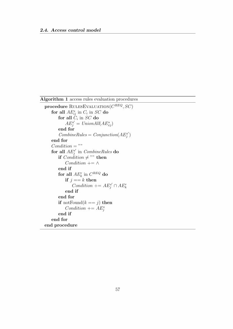
2.4. Access control model
Algorithm 1 access rules evaluation procedures
procedure RulesEvaluation(CREQ, SC)for all AEs
ij in Ci in SC dofor all Ci in SC do
AEs′j = UnionAll(AEs
xj)end forCombineRules = Conjunction(AEs′
j )end forCondition = ””for all AEs′
j in CombineRules doif Condition = ”” then
Condition += ∧end iffor all AEr
k in CREQ doif j == k then
Condition += AEs′j ∩ AEr
k
end ifend forif notFound(k == j) then
Condition += AEsj
end ifend for
end procedure
57
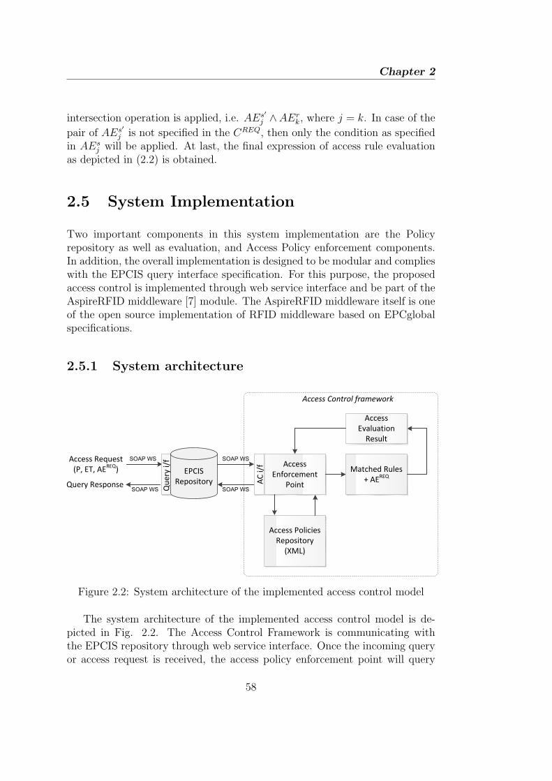
Chapter 2
intersection operation is applied, i.e. AEs′j ∧AEr
k, where j = k. In case of the
pair of AEs′j is not specified in the CREQ, then only the condition as specified
in AEsj will be applied. At last, the final expression of access rule evaluation
as depicted in (2.2) is obtained.
2.5 System Implementation
Two important components in this system implementation are the Policyrepository as well as evaluation, and Access Policy enforcement components.In addition, the overall implementation is designed to be modular and complieswith the EPCIS query interface specification. For this purpose, the proposedaccess control is implemented through web service interface and be part of theAspireRFID middleware [7] module. The AspireRFID middleware itself is oneof the open source implementation of RFID middleware based on EPCglobalspecifications.
2.5.1 System architecture
Access Policies
Repository
(XML)
Access Request
(P, ET, AEREQ
) Matched Rules
+ AEREQ
Query Response
Access Control framework
EPCIS
Repository
Qu
ery
i/f
SOAP WS
Access
Enforcement
Point
Access
Evaluation
Result
SOAP WS
AC
i/f
SOAP WS SOAP WS
Figure 2.2: System architecture of the implemented access control model
The system architecture of the implemented access control model is de-picted in Fig. 2.2. The Access Control Framework is communicating withthe EPCIS repository through web service interface. Once the incoming queryor access request is received, the access policy enforcement point will query
58
2.5. System Implementation
the Access Policies Repository to find the matching policies with the requestaccording to the procedure explained in Section 2.4 earlier. Once a set ofmatching policies or rules is found, it will be evaluated against the access re-quest. Finally, the result of the access control evaluation will be sent back toEPCIS repository through the Access Enforcement Point via the web interface.
The access policy enforcement is an important component in a policy basedaccess control implementation after an access decision has been taken. Inour implementation, the access control policy enforcement is implemented ina form of a modified QueryParams, i.e. the query parameters defined in theEPCIS specification. The advantage of this method is that the implementationcomplies fully with the EPCIS query interface specification while stay modu-lar without a necessity to greatly modify the EPCIS server implementation.Moreover, it does not depend of the actual implementation of the databasetechnology for the EPCIS repository. However, the main drawback is thatthis method does not fully leverage the proposed access control model dueto the nature of QueryParams description in the EPCIS specification wherethe parameter that is not explicitly mentioned in the QueryParams will beincluded in the query results. Nevertheless, it still allows us to perform anevaluation over most of the important functionalities of the proposed accesscontrol model. Additionally, if the access decision return an empty result, i.e.no matching policy is found in the repository, the query results of the EPCISquery interface implementation will return a SecurityExecption.
2.5.2 XML specification of access control policy
The policy repository and evaluation component implementation uses XMLand Java Architecture for XML Binding (JAXB) technologies. The proposedaccess control policy specification as explained in Section 2.4 is translated intoa set of XML specification and is practically stored as an XML file. Thanksto the JAXB technology, the access control policies can be created as an XMLfile and the stored access control policies can be translated into Java Objectsto be further evaluated.
The usage of XML for describing policies in the proposed access controlmodel is motivated due to the fact that the XML has been well accepted andwidely used in the heterogeneous IT enterprise environment across differentplatforms. Among others, XACML [13] is the most famous XML based accesscontrol system. Particularly in our system implementation, the XML is used itmodel the data structure of the proposed access policy elements as described
59

Chapter 2
in Section 2.4. To give an overview of the XML specification for the proposedaccess control model, X-Grammar notion as introduced in [5] is used.
2.5.2.1 Profiles
To match the incoming user request with the suitable access control policy,the notion of user profile (Profile in short) is used. Different types of profilesare created by the system administrator based on several set of attribute-valuepairs. The snippet of Profile XML representation in the X-Grammar, e.g.XProfiles is shown in Table 2.1.
Table 2.1: The grammar of of XProfiles in XML representation
<!- - Profiles Definition> ::=
<Profiles>
{<!- - Profile Definition>}+
</Profiles>
<!- - Profile Definition> ::= <!- - Attribute Definition> ::=
<Profile <Attribute
ProfileId = (profile ID)> AttrName = (name)
<Attributes> IsMandatory = ”true|false”
{<!- - Attribute Definition>}+ DataType = (type)>
</Attributes> (Attribute Value)
</Profile> </Attribute>
In Table 2.1, ProfileId is a unique Profile identifier to differentiate thisprofile with others. IsMandatory indicates whether or not the Attribute isa mandatory field. A set of Attribute along with the IsMandatory attributein the XProfile provides a vocabulary to express the attributes needed by theusers upon sending a Request.
2.5.2.2 Object
The Object element is used for creating access policy for a set of EPC IDs.It is also defined by the system administrator, in particular the tag’s ”owner”.To express a set of objects in the XML representation, the EPC ID patternsformat that is defined in the EPCGlobal TDS specification [9] is employed.The XML representation of the Object is referred as XObjects. The snippetof XObjects’ grammar is depicted in Table 2.2.
60

2.5. System Implementation
Table 2.2: The grammar of XObjects in XML representation
<!- - Objets Definition> ::=
<Objects
ObjId = (objects ID)>
{ <ObjectPattern> (EPC Pattern) </ObjectPattern> }+
</Object>
The ObjId is a unique group of objects identifier. According to [9], some ex-amples of ObjectPattern’s value are ”urn:epc:pat:gid-96:145.233.*”are ”urn:epc:pat:gid-96:145.233.[350-360]”. The first pattern example applies to any tag whoseGeneral Manager Number is 145, whose Object Class is 233, and whose Se-rial Number may be anything. The second example applies to any tag whoseGeneral Manager Number is 145, whose Object Class is 233, and whose SerialNumber is between 350 and 360.
2.5.2.3 Event Attribute
The Event Attribute refers to the fields of EPCISEvent classes and the queryparameters in the SimpleEventQuery that are defined in the EPCIS specifica-tion [8]. According to [8], the query parameters can be expressed by throughany comparison operators, e.g. =, <,≤, >,≥, over a single value or a set of val-ues. The XML specification of the Event Attribute in our proposed model needscapture such requirements to be compatible with the EPCIS specification. Inthe actual system deployment, the Event Attributes are part of the access re-quest which are translated from the EPCIS query parameters. The grammarof Event Attribute XML representation – referred as XEventAttribute – isshown in Table 2.3.
Table 2.3: The grammar of XEventAttribute in XML representation
<!- - EventAttribute Definition> ::=
<EventAttribute
AttrId = (Event Attribute ID)>
<Operator>{eq|lt|leq|gt|geq}</Operator>
{ <AttrributeValue> (value) </AttrributeValue> }+
</EventAttribute>
The AttrId is a unique name of the EPCISEvent class’s (and its subclasses)field as defined in [8]. The Operator is a comparison operator which can
61

Chapter 2
either be equal, less-than, less-than-or-equal, greater-than, and greater-than-or-equal. It is particularly designed to support general expression of the queryparameters in the SimpleEventQuery [8]. Finally, the AttributeValue canbe one or more based on the specification of the query parameters where theparameter value can be a single value or a list of values. For instance, theLT_eventTime query parameter can be described by using ”lt” Operator andonly one AttributeValue in the XML language, but the EQ_action uses ”eq”Operator and several AttributeValues.
2.5.2.4 Rule
A rule in the proposed access control policy consists of two mandatory ele-ments, namely an EventType and a set of Conditions. The grammar of RuleXML representation, which we call it as XRules, is shown in Table 2.4.
Table 2.4: The grammar of XRules in XML representation
<!- - Rules Definition> ::= <!- - Rule Definition> ::=
<Rules> <Rule
{<!- - Rule Definition>}+ RuleId = (rule ID)>
</Rules> <EventType>{OE|AE|QE|TE}</EventType>
<Condition>
{<!- - Logical Expression>}
</Condition>
</Rule>
RuleId is a unique identifier of the Rule. The value of EventType refersto either ObjectEvent, AggregationEvent, QuantityEvent, or TransactionEventrespectively. The Condition is expressed through Logical Expression, whosethe grammar in XML language is defined in Table 2.5.
The Logical Expression (LogicalExpr) consists of a set of Predicates, inwhich all the Predicates are evaluated by a logical operator op: AND, OR,or NOT. The LogicalExpr can also be nested inside the Predicate, allowingthe Condition to be expressed into different level of constraints. Apart fromthe nested LogicalExpr, each of the Predicate also comprises a comparisonoperator (Operator), a ParamName, and one or more ParamValue. Please notethat the Predicate’s grammar is almost similar to EventAttribute, exceptthat the ParamName is added as its element. This is because the proposed accesscontrol especially evaluates each Predicate within a Condition against thecorresponding EventAttribute constraint that is part of the access request.
62
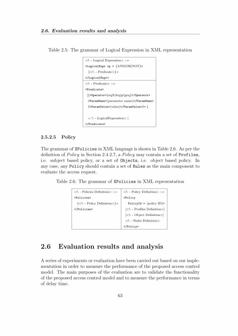
2.6. Evaluation results and analysis
Table 2.5: The grammar of Logical Expression in XML representation
<!- - Logical Expression> ::=
<LogicalExpr op = {AND|OR|NOT}>
{<!- - Predicate>}+
</LogicalExpr>
<!- - Predicate> ::=
<Predicate>
[{<Operator>{eq|lt|leq|gt|geq}</Operator>
<ParamName>(parameter name)</ParamName>
{<ParamValue>(value)</ParamValue>}+ }
< !- - LogicalExpression> ]
</Predicate>
2.5.2.5 Policy
The grammar of XPolicies in XML language is shown in Table 2.6. As per thedefinition of Policy in Section 2.4.2.7, a Policy may contain a set of Profiles,i.e. subject based policy, or a set of Objects, i.e. object based policy. Inany case, any Policy should contain a set of Rules as the main component toevaluate the access request.
Table 2.6: The grammar of XPolicies in XML representation
<!- - Policies Definition> ::= <!- - Policy Definition> ::=
<Policies> <Policy
{<!- - Policy Definition>}+ PolicyId = (policy ID)>
</Policies> [<!- - Profiles Definition>]
[<!- - Object Definition>]
<!- - Rules Definition>
</Policy>
2.6 Evaluation results and analysis
A series of experiments or evaluation have been carried out based on our imple-mentation in order to measure the performance of the proposed access controlmodel. The main purposes of the evaluation are to validate the functionalityof the proposed access control model and to measure the performance in termsof delay time.
63

Chapter 2
2.6.1 Evaluation procedures
For the testing purpose, one policy for a particular user profile is prepared.The policy consists of different rules with several conditions for different EPCISevent types. It is important to note that since generating EPCIS events alreadyrequires some complex procedures, we focuses on generating only one type ofbusiness event in the test scenario. Hence, the generated EPCIS events arealways having fixed event attributes values (V Eij), except for the eventTime,recordTime and EPC ID. As a result, the final access control enforcementmainly depends on conditions related to eventTime and EPC ID parametersor attributes in the practical experiments.
Regarding the first objective of this evaluation, it is shown that the accesscontrol works as it should be. The query results only returns the EPCIS eventdata that fulfil the conditions set in the policy and the final access decision. Onthe other hand, a SecurityException will be returned if there is no matchingpolicy found in the access policy repository.
Concerning the second objective of the evaluation, the delay performanceof the proposed access control model is compared against the EPCIS systemwithout any access control applied. For this purpose, we have tested ourproposed access control model on a system with Intel Core i7 2.80 GHz CPU, 8GB RAM, running Windows 7, and Java 6.31. In addition, an Apache Tomcat6.35 server is used to deploy all the AspireRFID Middleware modules as wellas our access control module, and a MySQL 5.2 Server is used as the EPCISevents data repository. Although the measurement results strongly dependanton the implementation, nevertheless we can expect to draw some qualitativeconclusion out of the results and further improve the system implementationif necessary.
Two measurement scenarios are carried out to observe the delay perfor-mance and behaviour of the implemented proposed access control model. Thedelay is defined as the time consumed between the query request being sentand received by the EPCIS query client, i.e. Treceived−Tsent. For each scenario,the same measurement point is done repeatedly for 700 times. For the purposeof explanation in the rest of this chapter, we will refer the case when the accesscontrol is used as the first case and the second case refers to the case whenaccess control is not used.
64

2.6. Evaluation results and analysis
2.6.2 The impact of varying the number of read tags
The first scenario aims to observe the delay time behaviour when the numberof read tags in each event stored in the EPCIS repository is varied. In thisscenario, the number of EPCIS events are fixed to three events at the EPCISrepository. It should be noted that the query results of the first case alwaysreturns one EPCIS events, while the second case always returns all three eventssince no access control is applied.
0
0.05
0.1
0.15
0.2
0.25
0 5 10 15 20
Tim
e (
se
co
nd
s)
Number of Tags
Query Time for different number of tags with 95% confidence interval
with Access Control (first case)without Access Control (second case)
Figure 2.3: Query delay time for different number of tags with 95% confidenceinterval
There are two important findings that can be derived based on the results ofthis scenario which is shown in Fig. 2.3. First, the average delay of the first caseis three times higher than that of the second case. This finding is quite expectedbecause it involves extensive XML processing, e.g. creating and parsing ofSimple Object Access Protocol (SOAP) message and parsing the access policy,which is time consuming. The delay performance could be improved in generalthrough a more tightly coupled implementation with the expense of sacrificingthe flexibility and modularity of such an open system. Second, the EPCISquery delay time for both cases is relatively constant regardless of the numberof tags read in each EPCIS event. Although some small variation is shown inthe first case, the confidence interval margin is rather high and it could be dueto the inconsistency of web service invocation of access control service. Thus itis quite safe to neglect the small variation. Nevertheless, the second finding is
65
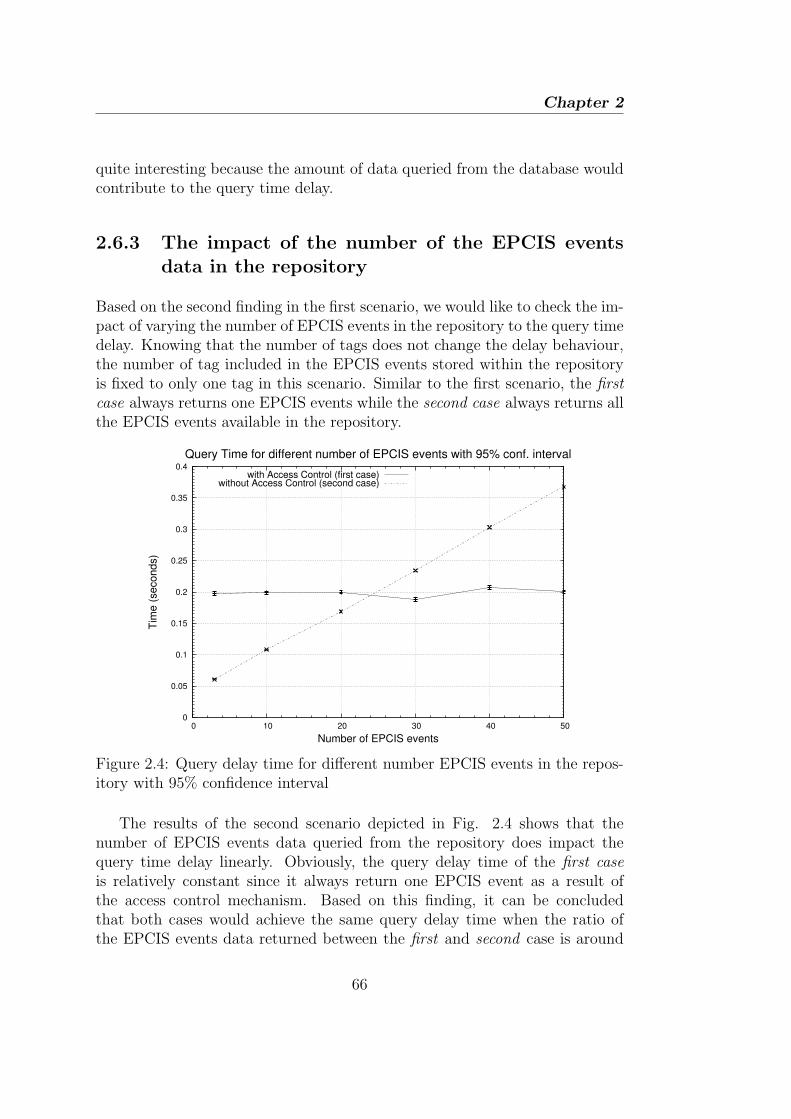
Chapter 2
quite interesting because the amount of data queried from the database wouldcontribute to the query time delay.
2.6.3 The impact of the number of the EPCIS eventsdata in the repository
Based on the second finding in the first scenario, we would like to check the im-pact of varying the number of EPCIS events in the repository to the query timedelay. Knowing that the number of tags does not change the delay behaviour,the number of tag included in the EPCIS events stored within the repositoryis fixed to only one tag in this scenario. Similar to the first scenario, the firstcase always returns one EPCIS events while the second case always returns allthe EPCIS events available in the repository.
0
0.05
0.1
0.15
0.2
0.25
0.3
0.35
0.4
0 10 20 30 40 50
Tim
e (
se
co
nd
s)
Number of EPCIS events
Query Time for different number of EPCIS events with 95% conf. interval
with Access Control (first case)without Access Control (second case)
Figure 2.4: Query delay time for different number EPCIS events in the repos-itory with 95% confidence interval
The results of the second scenario depicted in Fig. 2.4 shows that thenumber of EPCIS events data queried from the repository does impact thequery time delay linearly. Obviously, the query delay time of the first caseis relatively constant since it always return one EPCIS event as a result ofthe access control mechanism. Based on this finding, it can be concludedthat both cases would achieve the same query delay time when the ratio ofthe EPCIS events data returned between the first and second case is around
66

2.7. Discussions
1 : 25. Consequently, the delay gap between both cases as shown in Fig. 2.3would be bigger if the result of access control evaluation would return morethan one EPCIS events data. This ratio could be improved through a moreefficient implementation.
2.7 Discussions
Earlier in this chapter, we have mentioned several requirements of access con-trol model in an inter-enterprise RFID system, and how the proposed modelfulfilled those requirements. In this section, we will present several importantfeatures of a secure system – in particular an access control for big data sys-tem – that are constituted in the proposed access control model. Furthermore,some qualitative comparisons with other access control models will also begiven.
• High-granularity: The proposed access control model provides high-granularity since it does not allows the access only based on permit ordeny action, but based on some specific types of data or context infor-mation. The level of granularity can be defined in the access policy bythe system or security administrator of the system.
• High privacy: The high-granularity of access control policy provideshigh level of privacy to the business activities related information storedin the EPCIS repository.
• Trust: The access policy is applied to each user automatically basedon some pre-defined user profiles, and a user is assigned to a particularuser-profile based on trust relationship and contextual information.
• Flexibility: The proposed access control policy model offers high flex-ibility which is favourable in a big data system. It allows relative timedefinition instead of fixed time, EPC ID definition based on the EPCpattern, and automatic user assignment to user-profile through trust in-formation.
• Inter-operability: The proposed access control model complies withthe EPCIS Specification which is an open standard. The proposed sys-tem is also implemented as a web service which is highly inter-operable,i.e. independent of any specific programming language or server imple-mentation.
67
Chapter 2
In comparison with other existing access control, the proposed access con-trol model is better as compared to them in the following aspects:
• Trust-based X-GTRBAC [4] : Our proposed access control model allowsa way to incorporate trust in assigning user-profile to users which is quitesimilar to the approach presented in [4]. However, [4] does not fit therequirement of providing high-granularity access to data, particularly inan inter-enterprise RFID system.
• AAL [6] : A quite similar approach of a fine grained access enforcementspecially designed for the EPCIS events data that is proposed in ouraccess control model, was also introduced in [6]. However, automaticway of assigning some access policy to a user was not considered in [6],which gives a lot of burden to the system administrator, thus unrealis-tic for the real system. Moreover, its SQL query rewriting method forthe access enforcement, does not inter-operable with the EPCIS imple-mentation that is not based on the Relational Data Base ManagementSystem (RDBMS).
2.8 Conclusion
Access control management in an inter-enterprise RFID system is a great chal-lenge, since such system allows the tracking and monitoring of large numbersof things, i.e. a path towards realizing the IoT vision. The most challengingaccess control problems in such a system are in providing high-granularity ac-cess of RFID events data, known as EPCIS events, with flexibility and efficientaccess policy management over a very dynamic and huge amounts of EPCISevents data. A novel access control model to address these problems has beenproposed in this chapter along with complete definition of access control modeland evaluation through the system implementation of the model. The findingsin the evaluation show that the proposed access control model is consistentand could achieve less query time delay than the inter-enterprise RFID systemwithout access control if the ratio of the returned EPCIS events data is lessthan 1 : 25.
The proposed access control model relies on the trusted third parties en-tity to obtain the user profile, but the mechanism on dealing with such trustmanagement has not been addressed yet. Incorporating trust into the accesscontrol model, i.e. through PKI Certificate Authority (CA), is one possibil-ity of the future work. Another direction targeted in the near future is to
68

2.8. Conclusion
improve the current system level implementation, especially in addressing thelimitation described in Section 2.5.
69

Chapter 2
2.9 References
[1] Bayu Anggorojati, Parikshit N. Mahalle, Neeli R. Prasad, and RamjeePrasad. Secure access control and authority delegation based on capabilityand context awareness for federated iot. In Fabrice Theoleyre and Ai-Chun Pang, editors, Internet of Things and M2M Communications. RiverPublisher, 2013.
[2] Luigi Atzori, Antonio Iera, and Giacomo Morabito. The internet of things:A survey. Computer Networks, 54(15):2787 – 2805, 2010.
[3] Elisa Bertino, Piero Andrea Bonatti, and Elena Ferrari. Trbac: A tem-poral role-based access control model. ACM Trans. Inf. Syst. Secur.,4(3):191–233, August 2001.
[4] R. Bhatti, E. Bertino, and A. Ghafoor. A trust-based context-aware accesscontrol model for web-services. In Web Services, 2004. Proceedings. IEEEInternational Conference on, pages 184 – 191, july 2004.
[5] Rafae Bhatti, Arif Ghafoor, Elisa Bertino, and James B. D. Joshi. X-gtrbac: an xml-based policy specification framework and architecture forenterprise-wide access control. ACM Trans. Inf. Syst. Secur., 8(2):187–227, May 2005.
[6] Eberhard Grummt and Markus Muller. Fine-grained access control for epcinformation services. In Proceedings of the 1st International Conferenceon The Internet of Things, IOT’08, pages 35–49, Berlin, Heidelberg, 2008.Springer-Verlag.
[7] http://wiki.aspire.ow2.org.
[8] EPCglobal Inc. Epc information services (epcis) version 1.0.1 specifica-tion. September 2007.
[9] EPCglobal Inc. Gs1 epc tag data standard 1.6 - ratified standard. Septem-ber 2011.
[10] J.B.D. Joshi, E. Bertino, U. Latif, and A. Ghafoor. A generalized temporalrole-based access control model. Knowledge and Data Engineering, IEEETransactions on, 17(1):4 – 23, jan. 2005.
[11] Tom Karygiannis, Bernard Eydt, Greg Barber, Lynn Bunn, and TedPhillips. Guidelines for securing radio frequency identification (rfid) sys-tems - recommendations of the national institute of standards and tech-nology. NIST Special Publication, April 2007.
70

2.9. References
[12] R.S. Sandhu, E.J. Coyne, H.L. Feinstein, and C.E. Youman. Role-basedaccess control models. Computer, 29(2):38 –47, feb 1996.
[13] XACML. https://www.oasis-open.org/standards#xacmlv2.0.
71


3Secure Open M2M-RFID Middleware
The addressing and networking are amongst the most important issues in or-der to make the IoT concept a reality. In the RFID based IoT context, themost challenging issue is on the integration of the RFID network into the IPnetwork. The development of the RFID technology, which is driven mainlyby the logistic related industries, is based on enterprise system that does nottake full advantage of the IP based networking features, such as the mobilitymanagement. On the other hand, most of the existing works towards the in-tegration of RFID and IP network do not take the full advantage of all theRFID middleware components defined in the EPCglobal standard. Therefore,the full integration of RFID middleware with the IP network through a testbedimplementation which is fully compliance with the EPCglobal standard andhaving the location and mobility management at the same time, is the maincontribution of this work. The performance of our proposed work is measuredin terms of delay in two cases, i.e. tags registration and tracking, and there-after it is compared with the existing RFID middleware implementation. Themeasurement results show that the delay of our proposed work is significantlylower than that of existing solution, especially in the tags registration case.
73

Chapter 3
3.1 Introduction
The IoT is a novel paradigm in which the basic idea is to enable the interactionand cooperation of pervasive things or objects, such as RFID tags, sensors,actuators, etc, with their neighbors to reach common goals [2], and to beaccessible through internet. RFID as one of technology that enables objectlevel service on the internet, follows a certain standard, namely EPCGlobalstandard [8], in order to realize the IoT vision on RFID.
One of the major problem in current RFID network architecture is that ofits infrastructure has a limited accessibility in the global IP network. EPC-global standard has been driven mainly by the industry sectors that realyutilize RFID and gain benefits from it, e.g. logistics and supply chain, in aform of RFID middleware that aims to inter-connect the RFID system withenterprises IT infrastructure. As a result, the existing EPCglobal specifica-tion is very enterprise and middleware ”oriented”, e.g. focuses on adoptingweb-service/SOAP technology which is computationally heavy for low-poweredmobile device. In the context of the RFID tag tracking service, the EPCglobalRFID middleware relies on an entity called ONS which requires the client toaccess directly a computationally heavy service provided by the EPCIS queryinterface. Moreover, the root ONS which is an application of DNS has nosupport on mobility. By far, the mobility is not a very important issue sincebiggest customers of RFID technology are mostly logistic industries which donot really require real-time tracking. However, when a sensing capability isincluded within the RFID tag and real-time monitoring is required, mobilitybecomes an important part to be considered. By having all those aspects to-gether in mind, the main objectives of this work are to increase the accessibilityof RFID data over the internet with mobility support in the current EPCglobalspecification, while keeping all the advantages of the EPCglobal based RFIDmiddleware.
With its support in mobility management, SIP is a strong candidate toprovide such functionality in the RFID. Besides that, SIP is widely used inmany of the popular IP networking services such as Voice over IP (VoIP),tele/video-conference, IP Multimedia Subsystem (IMS), etc, thus suitable forthe purpose of integrating RFID with the global IP network. However, mostof the SIP based proposed solution did not leverage the rich functionality ofRFID middleware as defined by EPCglobal standard. The main contributionof the proposed solution is that it takes the full benefit of the RFID middle-ware defined in the EPCglobal architecture, which allows us to obtain richerinformation such as business context information. Moreover, it provides the
74

3.2. Related Works
RFID location management and integration with the Next Generation Net-work (NGN) through SIP functionality.
Besides the location management, security and privacy are of the mostimportance for the RFID system, especially when the RFID events data is ac-cessible across several different organizations. In Chapter 2, a fine-grained andefficient access control for the inter-enterprise RFID system has been proposed.The proposed access control system provides solution to problems in such asystem, such as granularity, privacy, trust, flexibility, and inter-operability.From the system architecture perspective, applying access control before theEPCIS component (i.e. at the Tracking module or the proposed SIP gateway)is intuitively considered to be more secure than at the EPCIS because it actsas the first “gateway” in providing access to the EPC tags ID tracking requestbefore reaching the EPCIS. However, it is necessary to evaluate the perfor-mance of the proposed location management architecture for the RFID systemcombined with the access control model proposed in Chapter 2 to measure theeffectiveness of such methods objectively.
The remaining of this chapter will be organized as follow. The architectureEPCGlobal and SIP network is presented in section 3.2. Section 3.3 describesour proposed solution in terms of architecture and protocol.The testbed im-plementation of our proposed architecture is explained in 3.4. Performanceevaluation based on the testbed implementation along with some discussionis presented in section 3.5. Finally conclusion and future insight are given insection 3.6.
3.2 Related Works
An approach to fully convert EPCglobal into SIP network to be compatiblewith IP based solution was proposed in [3]. It introduced an entity namedSurrogate User Agent (SUA) which acts as a SIP Client, i.e. performing theSIP signalling that supports the location management. The types of SIP sig-nalling message performed by SUA are REGISTER and INVITE. The REG-ISTER message is used in the location registration procedure and INVITEmessage is used in the tag tracking procedure. The authors of [3] also intro-duced an entity called SRMS Name Server (SNS) which has the similar role asDNS in the internet world or ONS in the RFID network, but it translates theEPC tag ID into a SIP URI format instead of translating URL into IP addressor EPC tag ID into an RFID tracking or EPCIS query service interface. How-ever, it was not clear how such translation is technically done. Moreover, with
75

Chapter 3
regards to an RFID middleware functionality, SUA only performs tag filteringwhich is a small portion compare to the overall RFID capabilities according tothe EPCglobal standard.
Another approach to integrate the RFID network with the global IP net-work was introduced in [12], in which an IP based infrastructure to retrieveEPC tag ID’s location was proposed. The proposed architecture consists ofRFID readers, location database, RFID agent, location server, and name server.In the proposed architecture, the registration and tracking are also introducedin order to manage the location of the RFID tag, and then a SIP-based RFIDlocation management system is again used as a proof of concept. However,the paper does not explain clearly how the tag ID is translated into a namethat can be recongnized in SIP, i.e. SIP URI, in fact the paper assumes ageneric name such as doctor1. More importantly, the RFID middleware is noteven utilized in the proposed architecture, thus the full advantage of RFIDmiddleware cannot be leveraged by the platform.
ROADS (RFID Office Application for Document tracking over SIP) [11] isanother attempt to integrate RFID with the global IP network. The paperemphasized its solution on the compatibility with NGN, in particular withthe IMS which is also based on SIP. The SNS entity which was introducedin the [3], and SIP for Instant Messaging and Presence Leveraging Extension(SIMPLE) protocol which is a transport of Instant messages in SIP that worksbased on publish-subscribe principle are also introduced in the ROADS system[11]. Similar to the previous solutions, this system does not leverage the fulladvantage of an RFID middleware.
On the other hand, the development of RFID middleware based on theEPCgloblal standard has been done by several companies as licensed and pro-prietary solutions as well as by the open source communities. One of theexisting open source RFID middleware is AspireRFID [10] which has beenpreviously described in section 1.3.2. It introduced some components thatextends the original EPCglobal standard, specially Tracking Service that pro-vides the tracking service and interface between ONS and EPCIS. However, itrelies fully on the web service implementation which does not support mobilitymanagement and it is heavy weight to be implemented in the mobile devices,such as smart phone and tablet.
3.2.1 Contributions to the existing works
According to the review of the existing works on the IP based RFID loca-tion and mobility management solutions as well as the RFID middleware, it
76

3.3. Proposed architecture
is clear that an integrated solution that combine both solutions into a singleplatform. The major contribution in this work is to realize an integration ofan EPCglobal RFID with the global IP network based on SIP, which provideslocation and mobility management functionality and also leverages the EPC-global based RFID middleware capabilities. This means that the platform willbe incorporated with the business contexts information and more light weightwhich means that the performance will be more efficient. On top of it, theplatform is also integrated with the security access control designed especiallyfor the inter-enterprise RFID systtem as explained in Chapter 2.
3.3 Proposed architecture
To achieve the objectives as described earlier in Section 3.1, a system architec-ture is proposed as depicted in Fig. 3.1. The proposed architecture consistsof the components from AspireRFID middleware [10] and SIP components,along with the interfaces enabling their integration. Besides that, a protocolto allow communication between different components and identity translationbetween two different systems, e.g. RFID and SIP, is also proposed.
3.3.1 EPCglobal RFID Middleware – SIP Architecture
EPCIS
Repository
Ca
ptu
re I/F
Qu
ery
I/F
Qu
ery
I/F
Qu
ery
Ca
llb
ack
I/F report
Subscribe
Poll
Query results
SIP GW
(Connector)
DNSLookup home
domain
Registrar
@visiting and/
or home
domain
Register Tag ID with
corresponding SIP-GW
address
Tracking
request/resultTracking
Client
BEG
Events
Data
Master
Data
ECReportALE
Server
RFID
Readers
RFID
Readers
RFID
Readers
Raw
Data
Raw
Data
Raw
Data
NOTES: RFID Data Flow
Tracking Flow
Components that runs SIP protocol
EPCGlobal components
ASPIRE RFID middleware component
Figure 3.1: Proposed EPCglobal-SIP architecture
Each of the component in the proposed EPCglobal-SIP architecture shownin Fig. 3.1 is briefly explained in the following subsections in order to give anidea of how the overall system works.
77

Chapter 3
3.3.1.1 ALE Server
It handles the connection with RFID readers and the collection of RFID rawdata. Furthermore, it performs filtering of RFID tags with certain pattern ofEPC ID and with certain kind of action, e.g. addition, current, or deletion ofRFID tags passing the reader. Therefore, only RFID data that matches criteriasets by the filter can be passed to the next component of RFID middleware,e.g. BEG, in the form of ECReport (Event Cycle Report).
3.3.1.2 BEG
BEG is a component proposed in ASPIRE RFID Middleware [10] as an exten-sion to EPCglobal architecture. It essentially processes the report from ALEserver, and then send the data into the EPCIS Repository through the EPCISCapture Interface. The forwarded data to EPCIS repository depends uponthe business transaction that is defined in the BEG, known as Master Data.BEG is able to retrieve those available Master Data in the EPCIS repositorythrough EPCIS Query Interface.
3.3.1.3 EPCIS
EPCIS is the heart of RFID middleware based on the EPCglobal architectureframework. Its main functionality is to process two kinds of data, namelyEvent Data and Master Data [6]. Given that, EPCIS transforms the Fil-tered raw RFID data into more meaningful information in regards to businesstransaction, e.g. the transaction ID, type of business step, business location,disposition, etc. In order to enable the sharing of information in the repos-itory to other components, EPCIS has two types of interface called Captureand Query interfaces. In the query interface, there are two available meth-ods to query the data in EPCIS repository, namely “poll” and “subscribe”.The “poll” method allows the query results to be returned once it is invoked,while the“subscribe”method allows the subscriber to retrieve the query resultsperiodically according to the time period that is defined in the subscription.Moreover, the“subscribe”method requires a so called Query Callback interfaceto allow it sending a periodical query report to the subscriber.
78
3.3. Proposed architecture
3.3.1.4 SIP Gateway
SIP Gateway is the main component that enables the communication betweenRFID middleware and other devices through SIP protocol. In the proposedarchitecture, SIP gateway has two main functionalities: location or mobilitymanagement of RFID tags using SIP protocol, and tracking of RFID tag.Based on the architecture depicted in Fig. 3.1, those two main functionalitiesare represented by orange and blue lines. The mobility management which isrepresented by orange line is accomplished by applying ”subscribe”method tothe EPCIS Query interface which returns periodical query report, and then byinvoking a SIP ”REGISTER”message any time a new tag ID is reported. Onthe other hand, the tracking of RFID tag is initialized by a SIP ”MESSAGE”sent by a tracking client that contains a tracking request. Upon receiving atracking request message, SIP gateway invokes a ”poll”method towards EPCISwhich returns some results and finally sends the tracking results back to track-ing client through another SIP ”MESSAGE”. It is important to mention that,the benefit of having a SIP based RFID tag tracking is to allow the trackingclient to access the EPCIS repository through the SIP gateway which is morelight-weight than the direct access to the EPCIS query interface, that is donein the traditional ONS based tag tracking.
3.3.2 SIP Protocol
The proposed architecture as explained earlier will not be able to perform mo-bility management and tracking of RFID tags functionalities properly withoutthe support of SIP protocols as well as its infrastructure. With that in mind,the details of SIP protocols along with the infrastructure supporting the pro-posed architecture will be explained in this section.
3.3.2.1 EPC ID-to-SIP URI translation and address resolution
In order for an RFID tag with a certain ID that follows EPCglobal standard tobe ”connected” in the internet world through SIP protocol, there are at least2 steps required: EPC-to-SIP URI translation and address resolution itself.The EPCglobal has defined ONS standard [7] that allows an EPC tag ID tobe resolved as an internet address through a specific DNS implementation.However, it does not support the EPC ID -to-SIP URI translation and furtherresolve it into an IP address along with the communication port and transportprotocol. [3] introduced a new entity called SNS (SIP Naming Service) that
79

Chapter 3
translates EPC-ID into SIP-URI and defines how the address translation isdone hierarchically. However, [3] does not explain clearly how the SIP addressresolution is being carried out. Given with limited information in the literature,we proposed a method that consists of 2 steps as mentioned earlier.
An important assumption in the translation process is that the EPC IDtranslation from the initial reading of RFID tag in the form of pure Hexadeci-mal or Binary format into a URI format has been done by a TDT [9] module,which practically can be part of the ALE server or running as a standaloneservice that is connected to ALE server. Given this assumption, a method totranslate an EPC ID in a pure identity URI form into a SIP URI is proposed.
A typical EPC ID in a pure identity URI form would be following a generalsyntax as follows:
urn:epc:id:EpcScheme:CompanyPrefix.ItemReference.(SerialNumber)
The EpcScheme can be gid, sgtin, grai, etc. The serial number is an op-tional field, since it is applicable in some of EpcSchemes but inapplicablein others. For example, the following EPC ID in a pure identity URI for-mat: urn:epc:id:gid:6776251.255.480, is mapped into the following SIP URI:sip:[email protected]. This means that the SIP domainof the URI example 6776251.gid.id.anydomain.com and the SIP user ID is480.255. Having the EPC ID mapped into the SIP URI, the complete addressresolution of SIP URI along with the port and transport protocol is done basedon the guideline in RFC 3263 [1]. Practically speaking, the address resolutionrelies on DNS infrastructure which is quite similar to the ONS, but its detailimplementation involves configuration of the SeRVice (SRV) record in DNSbesides the NAPTR record.
3.3.3 Access Control Module
The detail implementation of the access control module is thoroughly explainedin Section 2.5. The main difference on how the access control is integratedin the overall architecture between the one proposed in Chapter 2 and thiscurrent chapter where a SIP gateway is introduced, is that the access controlin Chapter 2 is performed at the EPCIS server level (as seen in Figure 2.2),while in this chapter it is performed at the SIP gateway level. Upon addingthe access control module into the proposed EPCglobal-SIP architecture, thearchitecture will look like as it is depicted in Figure 3.2.
80
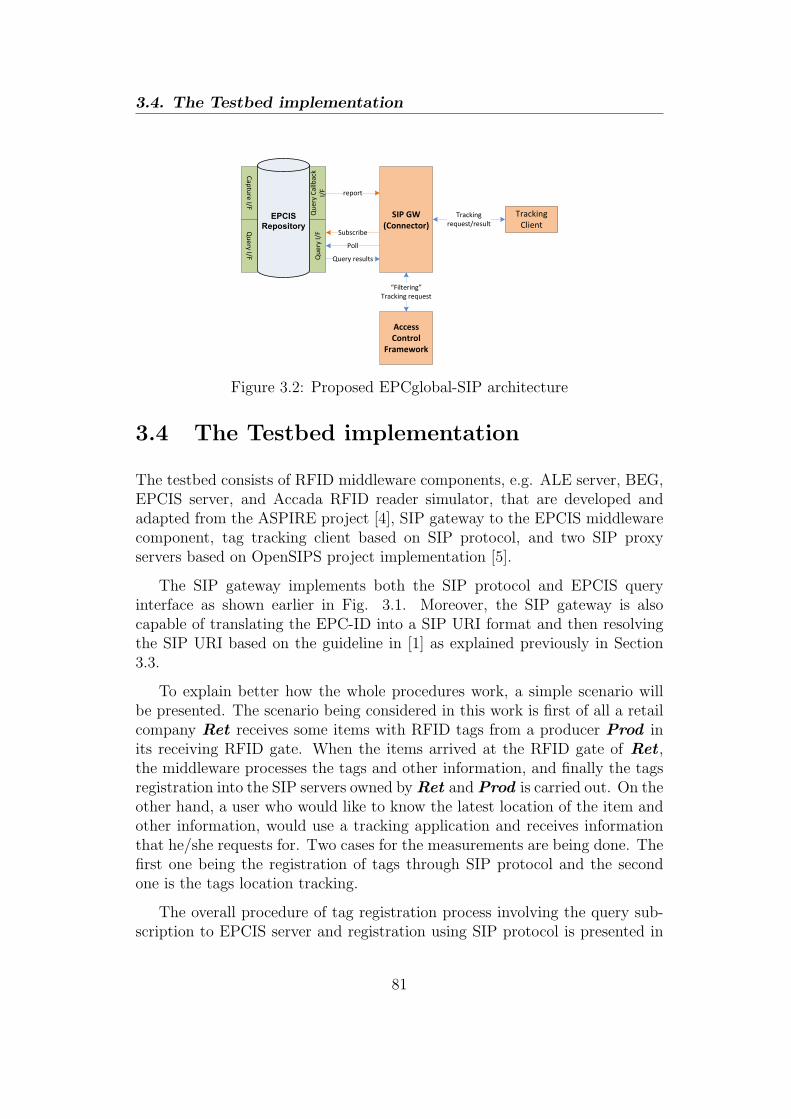
3.4. The Testbed implementation
EPCIS
Repository
Ca
ptu
re I/F
Qu
ery
I/F
Qu
ery
I/F
Qu
ery
Ca
llb
ack
I/F report
Subscribe
Poll
Query results
SIP GW
(Connector)
Access
Control
Framework
Tracking
Client
Tracking
request/result
“Filtering”
Tracking request
Figure 3.2: Proposed EPCglobal-SIP architecture
3.4 The Testbed implementation
The testbed consists of RFID middleware components, e.g. ALE server, BEG,EPCIS server, and Accada RFID reader simulator, that are developed andadapted from the ASPIRE project [4], SIP gateway to the EPCIS middlewarecomponent, tag tracking client based on SIP protocol, and two SIP proxyservers based on OpenSIPS project implementation [5].
The SIP gateway implements both the SIP protocol and EPCIS queryinterface as shown earlier in Fig. 3.1. Moreover, the SIP gateway is alsocapable of translating the EPC-ID into a SIP URI format and then resolvingthe SIP URI based on the guideline in [1] as explained previously in Section3.3.
To explain better how the whole procedures work, a simple scenario willbe presented. The scenario being considered in this work is first of all a retailcompany Ret receives some items with RFID tags from a producer Prod inits receiving RFID gate. When the items arrived at the RFID gate of Ret ,the middleware processes the tags and other information, and finally the tagsregistration into the SIP servers owned byRet andProd is carried out. On theother hand, a user who would like to know the latest location of the item andother information, would use a tracking application and receives informationthat he/she requests for. Two cases for the measurements are being done. Thefirst one being the registration of tags through SIP protocol and the secondone is the tags location tracking.
The overall procedure of tag registration process involving the query sub-scription to EPCIS server and registration using SIP protocol is presented in
81

Chapter 3
Ret SIP
Gateway
Ret EPCIS
(1) Subscribe
Query(2) New tag(s)
registered
(3) Report Query
(4) EPC-to-SIP URI
resolution
urn:epc:id:gid:6776251.255.480
Ret Registrar
Server
(5) REGISTER
Contact: [email protected]
(6) 200 OK
Prod Registrar
Server
(7) REGISTER
Contact: [email protected]
(8) 200 OK
Figure 3.3: Tag registration procedure
Figure 3.3. The tag registration process relies on the subscribe method of theEPCIS query interface in which the SIP subscribes to a particular event in theEPCIS (step 1 in Figure 3.3), i.e. a new tag is added into the EPCIS repos-itory (step 2 in Figure 3.3), and then a periodic message with a configurabletime interval would be sent to the SIP gateway as long as the event matchesthe subscription criteria (step 3 in Figure 3.3). As soon as a new tag is readby the reader and processed by the middleware up until the SIP gateway, thetag registration process by using SIP protocol is performed. Before that, SIPgateway would perform an EPC-to-SIP URI translation as well as a SIP ad-dress resolution by using a DNS query (step 4 in Figure 3.3). Since the tagis received at the Ret premises which is considered as the foreign domain tothe Prod , the tag registration is done to both Ret ’s and Prod ’s RegistrarServers. Upon the registration at the Prod ’s home registrar server (step 5 inFigure 3.3), the domain part of the Contact address in the SIP header containsthe Ret ’s domain, which in this case is essentially corresponds to the Ret ’sProxy Server. The purpose of this is that when a tracking request is receivedat the Prod ’s Proxy Server, the request will be forwarded to the Ret ’s ProxyServer which will be explained in a more detailed when we describe the track-ing procedure later on in this section. Further on, upon the the registrationat the Ret ’s local Registrar Server (step 7 in Figure 3.3), the domain partof the Contact address in the SIP header contains the IP address of the SIPgateway which is the main contact point in querying the requested EPC tagID to the EPCIS server. Finally the 200 OK message will be sent back to theSIP gateway upon successful registrations (step 6 and 8 in Figure 3.3).
82
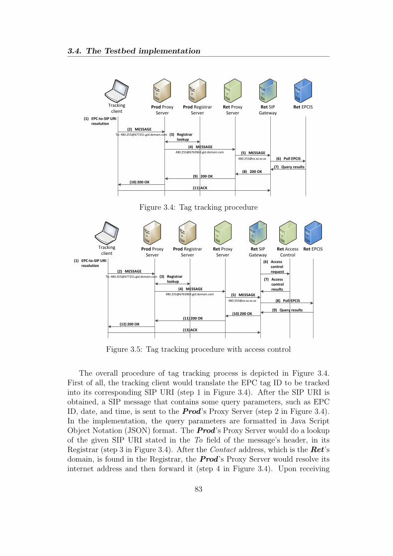
3.4. The Testbed implementation
Tracking
clientProd Proxy
Server
Prod Registrar
Server
Ret Proxy
Server
Ret SIP
Gateway
Ret EPCIS
(1) EPC-to-SIP URI
resolution
(2) MESSAGE
To: [email protected] (3) Registrar
lookup
(4) MESSAGE
[email protected] (5) MESSAGE
[email protected] (6) Poll EPCIS
(7) Query results
(8) 200 OK
(9) 200 OK
(10) 200 OK
(11) ACK
Figure 3.4: Tag tracking procedure
Tracking
clientProd Proxy
Server
Prod Registrar
Server
Ret Proxy
Server
Ret SIP
Gateway
Ret EPCIS
(1) EPC-to-SIP URI
resolution
(2) MESSAGE
To: [email protected] (3) Registrar
lookup
(4) MESSAGE
[email protected] (5) MESSAGE
[email protected] (8) Poll EPCIS
(9) Query results(10) 200 OK
(11) 200 OK
(12) 200 OK
(13) ACK
Ret Access
Control
(6) Access
control
request
(7) Access
control
results
Figure 3.5: Tag tracking procedure with access control
The overall procedure of tag tracking process is depicted in Figure 3.4.First of all, the tracking client would translate the EPC tag ID to be trackedinto its corresponding SIP URI (step 1 in Figure 3.4). After the SIP URI isobtained, a SIP message that contains some query parameters, such as EPCID, date, and time, is sent to the Prod ’s Proxy Server (step 2 in Figure 3.4).In the implementation, the query parameters are formatted in Java ScriptObject Notation (JSON) format. The Prod ’s Proxy Server would do a lookupof the given SIP URI stated in the To field of the message’s header, in itsRegistrar (step 3 in Figure 3.4). After the Contact address, which is the Ret ’sdomain, is found in the Registrar, the Prod ’s Proxy Server would resolve itsinternet address and then forward it (step 4 in Figure 3.4). Upon receiving
83
Chapter 3
the message, Ret ’s Proxy Server would forward it to the SIP gateway (step5 in Figure 3.4), that can be obtained from the Ret ’s Registrar after theregistration process. Further on, the SIP gateway would invoke a poll methodthrough the EPCIS query interface, unlike in the tags registration process thatuses subscribe method (step 6 in Figure 3.4). The EPCIS repository wouldthen return the query results to SIP gateway according to the query parametersthat are requested (step 7 in Figure 3.4). Upon receiving the query results,the SIP gateway would send a 200 OK response message including the queryresults down until the tracking client side (step 8-10 in Figure 3.4). Finally,an ACK message is sent to the SIP gateway (step 11 in Figure 3.4). Uponintegrating the access control mechanism in the tag tracking procedure, someadditional steps are required in the overall tracking process as shown in Figure3.5. Those additional steps are essentially an access control request and a setof access control resutls sent by the SIP gateway to the access control moduleand vice versa (steps 6 and 7 in Figure 3.5).
3.5 Results and discussion
3.5.1 Measurement procedures
A series of experiments have been carried out to measure the performance ofthe proposed system architecture in both tags registration and tracking cases,which is particularly interesting due to the fact that a high number of tags arebeing read at one cycle in logistics, shipping, and such. The parameter that isbeing measured is the time consumed to perform each operation over differentnumber of tags. The time consumed for the tags registration is defined as thetime between the first SIP REGISTER request message among all the tagsbeing sent and the last SIP 200 OK response message being received by theSIP gateway. Similarly, the time consumed for the tags tracking is defined asthe time between the first SIP MESSAGE being sent and the last received SIP200 OK response message. For each number of tags, 700 measurements havebeen done for the tags tracking case, and more than 600 measurements weretaken for the tags registration case. The measurement results of our proposedmethod are then compared with the ONS Tracking Service from ASPIRE [4],which will be referred as the reference method, under the similar scenario. It isimportant to note that there exists other traffics other than the traffic for themeasurement purpose, e.g. LAN and internet traffic, during the experimentdue to the needs of the DNS. As a result, that factor greatly affects the delay of
84

3.5. Results and discussion
some tiny numbers of measured data which were discarded in the final statisticsanalysis.
3.5.2 Analysis of measurement results
0
0.2
0.4
0.6
0.8
1
1.2
0 5 10 15 20
Re
gis
tra
tio
n T
ime
(se
co
nd
s)
Number of Tags
RFID tag Registration Time with 95% confidence interval
Proposed methodReference method
Figure 3.6: Time consumed in the registration process for different number oftags with 95% confidence interval
The measured delay as a result of the experiments for tags register andtracking cases are depicted in Fig. 3.6 and Fig. 3.7 respectively. Both mea-surement results show clearly that the delay in tag registration and trackingmechanisms of the proposed method are lower then the one being compared,especially in the registration mechanism in which the delays differ significantly.The main reason behind it is that because the reference method fully utilizesweb based operation that takes relatively high delay to perform, such as thetracking service methods as well as the EPCIS poll query, which involves webservice methods invocation and database query. That is why the delay of ref-erence method is significantly higher than the proposed method which is fullyutilizes SIP protocol in the tags registration case. This argument is even moreconfirmed when the two cases of our proposed method are being compared.Here, we can obviously see that the tags tracking process takes roughly morethan 10 times the delay of the other case. This is due to extra signalling andprocessing within the SIP Proxy servers, e.g. registrar lookup and address
85

Chapter 3
0
0.2
0.4
0.6
0.8
1
1.2
1.4
0 5 10 15 20
Tra
ckin
g T
ime (
seconds)
Number of Tags
RFID tag Tracking Time with 95% confidence interval
Proposed methodReference method
Figure 3.7: Time consumed in the tag tracking for different number of tagswith 95% confidence interval
resolution, as well as the query operation to the EPCIS server, that it has toperform. In fact, the query of EPCIS server takes around 5/6 of the total delayin the tags tracking process. Even so it is still higher than the delay of tagsregistration process which is obvious since more SIP signalling is involved, theprocess involving SIP signalling alone in the tags tracking procedure is signifi-cantly lower than the delay of the web based operation. Based on the findingsin Figure 3.7, we can also conclude that the proposed method is more scalablethan the reference one under the same condition. This behaviour is due to thedatabase query in the reference method is done twice, that is two times higherthan the proposed one, which makes the delay difference between two casesincreases almost double as the number of tags increases.
Furthermore, confidence interval has been calculated in order to check thereliability of the data. As stated earlier, a series of experiments of more than600 measurements for each scenario which is independent to each other andresults in a large enough population of data, implies that the distribution ofthe sample mean approach a normal distribution. This is true according to thecentral limit theorem for a large enough sample size as long as the populationhas a finite standard deviation. Therefore, it is safe to assume that the sampledata has normal distribution which is then used in deriving the 95% confidenceinterval values of the measured data, which are presented in Table 3.1.
86

3.5. Results and discussion
Table 3.1: 95% confidence interval values of the measured data
Proposed ReferenceRegister Tracking Register Tracking
2 tags 0.000134 0.000471 0.004006 0.0013575 tags 0.000208 0.001112 0.004607 0.00231510 tags 0.000618 0.002819 0.009175 0.00521315 tags 0.000672 0.004948 0.011330 0.00579920 tags 0.001979 0.007190 0.014357 0.010330
The confidence interval general trends show that, the higher the numberof tags the higher the 95% confidence interval values, although the values overdifferent tags does not have linear relationship. As the confidence intervalvalue is highly influenced by the standard deviation, this finding shows thatthe measured delay values varied a lot especially when high number of tagsare used. One of the reason is that because the message in the either caseis sent as an individual request message that represents an individual tag ID,especially for the case of the proposed method and the tags tracking case ofthe reference method. Therefore, the probability of the message being delayed,e.g. due to packet retransmission or congestion in the network, is higher whenmore individual messages are sent as a whole.
0
0.2
0.4
0.6
0.8
1
0 0.05 0.1 0.15 0.2
Actu
al F
requency (
%)
Register time (s)
CDF of measured register time using the proposed method
Register time CDF of 2 tagRegister time CDF of 5 tag
Register time CDF of 10 tagRegister time CDF of 15 tagRegister time CDF of 20 tag
Figure 3.8: CDF plot of the proposed method in the registration processes forvarious tags numbers
87

Chapter 3
0
0.2
0.4
0.6
0.8
1
0 0.2 0.4 0.6 0.8 1 1.2 1.4
Actu
al F
req
ue
ncy (
%)
Tracking time (s)
CDF of measured tracking time using the proposed method
Tracking time CDF of 2 tagTracking time CDF of 5 tag
Tracking time CDF of 10 tagTracking time CDF of 15 tagTracking time CDF of 20 tag
Figure 3.9: CDF plot of the proposed method in the tracking processes forvarious tags numbers
In addition, the Cummulative Distribution Function (CDF) plots of theproposed method for both registration and tracking cases are shown in Fig.3.8 and 3.9. Those CDF plots confirm the previous results that the SIP tagregistration process takes very low delay, i.e. less than 60 milliseconds for 20tags in average, and the confidence intervals increase as the number of tags isincreased in both cases.
3.5.3 The impact of access control in the tags trackingcase
In order to test the impact of access control in the tags tracking case in theproposed system architecture and the reference system, another series of mea-surement is performed similar to the procedure carried out in 3.5.1 for the tagstracking case. The measured delay of the experiment for tags tracking casewith the impact of access control is presented in Figure 3.10. The measurementresult shows a peculiar behavior of the proposed system architecture when theaccess control is applied, especially when there is 15 or more number of tagsto be tracked. Initially, the tags tracking time of the proposed system archi-tecture combined with the access control mechanism is comparable with thereference system even without access control, i.e. in the range of 0.5 second,
88

3.5. Results and discussion
0
2
4
6
8
10
0 5 10 15 20
Tra
ckin
g T
ime
(se
co
nd
s)
Number of Tags
RFID tag Tracking Time with 95% confidence interval
Reference method with ACReference method without AC
Proposed method with ACProposed method without AC
Figure 3.10: The impact of access control on the time consumed in the tagstracking for different number of tags with 95% confidence interval
for 10 or less number of tags. But it goes up as high as 5.5 seconds and 7.4seconds when the number of tags is 15 and 20.
The main reason of such strange behavior is because the access controlframework is implemented in web service, which is similar to the referencesystem, while the proposed system is based on SIP. As previously shown inFigure 3.5, the overall tag tracking procedure which is based on SIP protocol is“interrupted”by a time consuming web service based access control mechanism.In addition, the proposed tracking procedure requires the multiple tags to betracked one by one. As a result, the protocol necessitates the invoking of accesscontrol service in multiple times, depending on the number of tag to be tracked,thus the tracking time grows extremely high when the tags reach a certainnumber, e.g. 15 tags or more according to the results depicted in Figure 3.10.This problem does not occur in the reference system because both the referencetracking method and the access control rely on web service. Furthermore,the web service operation is invoked only once regardless of the tag numbers,i.e. one web service invocation each for the tracking and access control. Insummary, this result tells us that the access control mechanism needs to beimplemented in a more efficient way, yet maintaining the interoperability, i.e.compatible with the overall RFID middleware as well as the specific locationmanagement implementation method.
89
Chapter 3
3.6 Conclusion
The main contribution of this work is the integration of the EPCglobal basedRFID architecture with SIP to their full advantage, i.e. providing functionali-ties of RFID middleware as well as RFID mobility and location management.A testbed implementation has been developed and a series of experiments havebeen carried out to measure the performance of the proposed architecture interms of delay, for tags registration and tracking scenarios. Moreover, themeasurement results of the proposed architecture are then compared with areference method from an existing RFID middleware implementation. Theresults show that the proposed method performs significantly better than thereference method in terms of delay and scalability.
Some future directions of the development in this work include the inte-gration of the system with IMS, integration with cloud platform either at theRFID middleware component or the SIP as well as IMS network entities, andan implementation of the security and privacy mechanisms.
90
3.7. References
3.7 References
[1] Rfc 3263 - session initiation protocol (sip): Locating sip servers. June2002.
[2] Luigi Atzori, Antonio Iera, and Giacomo Morabito. The internet of things:A survey. Computer Networks, 54(15):2787 – 2805, 2010.
[3] Kideok Cho, Sangheon Pack, Taekyoung Kwon, and Yanghee Choi. Srms:Sip-based rfid management system. In Pervasive Services, IEEE Interna-tional Conference on, july 2007.
[4] http://wiki.aspire.ow2.org.
[5] http://www.opensips.org.
[6] EPCglobal Inc. Epc information services (epcis) version 1.0.1 specifica-tion. September 2007.
[7] EPCglobal Inc. Epcglobal object name service (ons) version 1.0.1. May2008.
[8] EPCglobal Inc. The epcglobal architecture framework. December 2010.
[9] EPCglobal Inc. Gs1 epcglobal tag data translation (tdt) 1.6 - ratifiedstandard. October 2011.
[10] John Soldatos, Nikos Kefalakis, Nektarios Leontiadis, Nikolaos Konstanti-nou, Nathalie Mitton, Loc Schmidt, Roudy Dagher, Mathieu David, BayuAnggorojati, Simone Frattasi, Neeli Prasad, Didier Donsez, Gabriel Pe-draza, and Kiev Gama. D3.4b: Core aspire middleware infrastructure.Technical report, ASPIRE, 2010.
[11] P. Solic, N. Rozic, and N. Ukic. Roads: Rfid office application for docu-ment tracking over sip. In Software, Telecommunications Computer Net-works, 2009. SoftCOM 2009. 17th International Conference on, september2009.
[12] P.N. Tran and N. Boukhatem. Ip-based rfid architecture and locationmanagement. In Software, Telecommunications and Computer Networks,2008. SoftCOM 2008. 16th International Conference on, sept. 2008.
91

4Secure Access Control and AuthorityDelegation based on Capability and
Context Awareness for IoT
Access control is a critical functionality in IoT, and it is particularly promisingto make access control secure, efficient and generic in a distributed environ-ment. Another an important property of access control system in the IoT isflexibility which can be achieved by access or authority delegation. Delega-tion mechanisms in access control that have been studied until now have beenintended mainly for a system that has no resource constraint, such as a web-based system, which is not very suitable for a highly pervasive system such asIoT. This chapter presents the CCAAC model including the authority dele-gation method, along with specification and protocol evaluation intended forfederated M2M/IoT. By using the identity and capability-based access con-trol approach together with the contextual information and secure federatedIoT, this proposed model provides scalability, flexibility, and secure authoritydelegation for highly distributed system. The protocol evaluation results showthat the capability creation and access mechanism of CCAAC is secure againsta rigorous man-in-the-middle attack, e.g. eavesdropping and replay attacks,and is able to provide authentication as well.
93

Chapter 4
4.1 Introduction
The Future Internet (FI) will be shaped by the rapid growth of the currentinternet in terms of penetration, services, capacity and contents along withultra-small yet powerful mobile communication devices. The vision of internetconnectivity by anyone, any time and anywhere, will be augmented by a newdimension, namely connectivity of anything driven by the advancements in thedevelopment of smart devices including WSN, RFID, Near Field Communica-tion (NFC), etc. This is often referred to as IoT and enables different modesof communication, i.e. things-to-person, things-to-things and person-to-thingscommunication along with various intelligent services and applications. A largenumber of research challenges remain in order to ensure the successful opera-tion of IoT and some of the most significant of these relate to the capabilitiesof the network to offer security, privacy and trust.
IoT is ubiquitous and heterogeneous in nature. As a result, a large numbersof risks and threats emerge that can threaten the system’s security and user’sdata privacy. Among others, access control is one of the main security issuesto be addressed in IoT that is highly pervasive. A novel access control model –CCAAC is proposed to overcome this issue. Furthermore, as IoT is character-ized by highly dynamic nodes connectivity and network topologies due to theever-changing nature of wireless channel, mobility, and factors such as limitedpower, a dynamic and flexible design of access control system that is suitablefor IoT is of the most importance. For this purpose, the proposed CCAACmodel also considers the delegation of authority in order to gain access to acertain resource which belongs to different security domain in a Federated IoTnetwork.
The chosen approach for the model with access control based on the capa-bility concept, and in particular the Identity based Capability (ICAP) system[8], is considered in order to cope with the scalability of IoT system since itis well suited for providing authentication and access control in distributedsystems. By using the capability concept, the proposed model to some extentalso contributes to the authentication mechanism, which will be shown laterin Section 4.7. Furthermore, in order to fulfil the flexibility and adaptabil-ity in IoT, context awareness and dynamic security as well as privacy policyenforcement is applied in the proposed model. The Context Aware SecurityManager (CASM) model originally proposed for a PN [18] will be used as areference point due its suitability in distributed systems, especially in the caseof federated IoT. Along with that, flexible access control system by meansof authority delegation method based on a dynamic capability propagation isalso included in the proposed model [1].
94

4.2. Related Works on Access Control and Authority DelegationModels
4.2 Related Works on Access Control and Au-
thority Delegation Models
Capability based access control was derived from the capability system con-cept in the computing world [15] in order to address the shortcomings of ACLbased models. Both capability based access control and ACL are two com-plementary traditional access control systems derived from an Access ControlMatrix (ACM). Basically, an ACM consists of several columns that list theobjects or resources to be accessed, and rows that list a set of subjects or userswho have privileges to access different resources. Each row in the ACM canalso be seen as a capability owned by a subject that needs to be presentedwhenever it wants to access any object or resource in a system.
A simple example of capability used in the real life is a ticket that allows apassenger to embark on different modes of city transportation, e.g. bus, tram,train, etc. If the ticket contains all the transportation modes in which thepassenger can embark, then the capability based access control is used. Oncontrary, if the system check whether the credential contained in the ticketis listed in the access control list, then the ACL is used. In comparison [3],capability based access control is better than ACL in tackling e.g. the con-fused deputy problem and other security threats, it is more robust due to itsdistributed architecture, it supports more levels of granularity, access right del-egation and revocation. The Identity based Capability or ICAP was proposedin [8] which solves the problem of capability propagation and revocation inclassical capability based access control.
In Context aWare Access Control (CWAC) [13], the surrounding contextof subjects and/or objects is considered to provide access but it has scalabil-ity issues and no support for delegation and revocation. In Context AwareRole Based Access Control (CARBAC) [14], context is integrated with RBACdynamically which is defined as characterization of the surrounding entitiesfor performing appropriate actions. With CARBAC each different role can beassociated with certain contexts. For instance, a Professor role in a universitycan be associated with some contexts, such as PhD degree, x years of researchexperience, and y numbers of journal publications in the related field. However,improper association of context and roles results in inefficiency in scalabilityand time and context dependency results in complicated delegation.
A Personal Trusted Device (PTD) [2] is used to provide access to lockedresources and places, which consists of access controllers, the PTD and anadministration point, while embedded security of the PTD is not considered.In [16], an access control model is designed as standalone components each
95

Chapter 4
managing its context and thus limiting the reuse and context sharing. [5]and [9] proposed solutions for decoupling the applications from the contextresources which require permanent access to the server. However, in a WirelessPersonal Area Network (WPAN) as one scenario considered in PN, access tofixed infrastructure cannot be guaranteed due to constraints like frequentlychanging connectivity, resource unavailability and battery power. In [17], anidentity establishment scheme for IoT as well as authentication mechanismbased on ECC and capability was proposed.
Research on delegation of authority using capability has been investigatedin [11] and [10]. [11] addressed the issue of role and/or permission delegationbased on a RBAC model in a cross-domain environment using capabilities. Thecentral idea behind their proposed mechanisms was the mapping of capabilitiesinto roles and permissions in each domain. Hasebe et al. extends the approachpresented in [11] by adding the delegation of task to be performed in the modelfor workflow systems in [10].
Research on dynamic authorization delegation in federated environmentbetween entities or machine-to-machine delegation has been reported by Gomiet al. in [7]. Authors of the paper investigated chain of delegation in multipleentities and how to provide secure delegation framework. To better illustratethe delegation chain in multiple entities being investigated in [7], we can thinkof a user who is authorized in his company’s web server and wanting to accesssome information from other company’s server, i.e. destination server. In thisscenario, his request has to go through his company’s server and other interme-diate servers in between before reaching the destination server. Consequently,the user has to delegate his authority over the chains of intermediate serversin a relay-like fashion. The delegation framework proposed in [7] also intro-duced Delegation Authority and Authentication Authority entities to enablesuch authorization delegation. Another related work in this topic has also beenreported by the same author, Gomi, in [6]. Unlike his previous work in [7], [6]focuses on the user-to-user delegation and does not consider multiple entitiesdelegation. The main contribution was a delegation framework in federatedenvironment using an access token, regardless of the access control model be-ing used. In this context, an access token is an opaque string representing adelegator’s authorization to delegate their privilege to a delegatee whom theyspecify, which does not contain any information about delegator’s credentials.The paper also explains the mechanism of issuing a token, asserting it into anauthorization document, and service provisioning based on the delegate token.
96

4.3. System Architecture
The existing delegation methods are designed mainly to serve web-basedservices which involve a large IT infrastructure. These kinds of delegation mod-els are not practically visible for an IoT system, which has a lot of constraints,e.g. power, memory, etc. It is important to mention that the delegation ofauthority by means of capability propagation is part of CCAAC overall designmodel. Therefore, delegation method in CCAAC is not an extension of anyexisting access control model, e.g. RBAC, as presented in most of the previousworks.
The federated IoT networking has not been much discussed in the litera-ture. There is a significant amount of work done in the context of a federateddevice-to-device or machine-to-machine communication known as PN feder-ation, which includes the networking, management, security framework andidentity management in [18]. Federated IoT environments based on the PNconcept [18] will be further elaborated in Section 4.3.2.
4.2.1 Contributions to the existing works
According to the review of the related works on access control and authoritydelegation, some challenges are still left open, especially in the context of IoT.The biggest challenge on the access control for IoT are the scalability and flexi-bility, not to mention the secure access control. As we understand already thatthe IoT is highly pervasive and distributed in nature, thus scalability aspectof access control system is one important characteristic to have. While accesscontrol system is usually centralized or ”distributed” in a particular entity, e.g.server, our approach is to distribute the complexity to the accessing entity byusing capability. The flexibility challenge in access control here refers to twothings: the flexibility in the process of access decision making by consideringthe contextual information and the flexibility in terms of authority delegation.Based on the review of challenges related to such requirements in Section 4.2,the proposed access control scheme will tackle both aspects at the same time.
4.3 System Architecture
4.3.1 System architecture to support the CCAACmodel
The system architecture for supporting the CCAACmodel is depicted in Figure4.1. It is important to note that the Personal Network (PN) [18] has beenreferred in this work due to its advance networking concept for device-to-device
97

Chapter 4
communication that opens a path as one candidate of network implementationin IoT. Correspondingly, the security framework brought up within the PNwould be a good starting point in designing a security framework, consideringtheir similarities in characteristics and requirements.
Security Decision Point
Policies
ProfilesAccess
List
Figure 4.1: System architecture for supporting the CCAAC
Security Decision Point (SDP) in Figure 4.1 is the most important modulein the system architecture to receive the capability creation or access requestand make the final decision of the request. Policies serves as Policies Repos-itory that consists of a collection of various policies for accessing availableresources or objects. Profiles serves as Profile Repository, which essentiallyconsists of subject as well as object profiles. Both of these components will bereferred to as Policies Repository and Profiles Repository later on in Section4.4. Finally, Access List plays an important role in supporting the capability-based authority delegation of access control by controlling the capability prop-agation as well as revocation through maintenance of a propagation tree asproposed in [8].
In principle, a new propagation tree is created at the Access List whenevera new capability is created, with the original capability owner becomes the rootof the tree. When the capability owner delegates his authority by propagatinghis capability to someone else, then the propagation tree is updated by addinga new node. The one who propagated the capability can revoke the authoritydelegated to someone else before by requesting a revocation message to AccessList. If the revocation message is valid, the corresponding node will be removedfrom the propagation tree.
4.3.2 Federated-IoT
Identity ”Federation” is known term within the web security world and refersto management of a web user’s identity across different security domains. Themain reason of enabling federation in the web environment is that the workflow of the system often requires a user that is authenticated in one domain
98

4.3. System Architecture
to be authenticated in other domains as well. However, a concrete definitionof the Federated IoT which is conceptually different as compared to the websecurity world, needs to be determined before addressing the issue of authoritydelegation in such environment.
First of all, the identity in the web-based system refers to a person’s identitywhile in IoT, identity refers to a device or ”thing”. Therefore, the interactionof identities in IoT is in the form of device-to-device communication.
Warehouse
Cluster
Factory
Cluster
Shop
Cluster 1
Shop
Cluster 2
Home
cluster
University
Cluster
Internet
infrastructure
IoT Private user network domain
IoT Retail Shop network domain
IoT Goods producer network domain
IoT network federation 1
IoT network federation 2
Figure 4.2: An example of Federated IoT network with delegation scenario
An example of federated IoT network in our context is depicted in Figure4.2. Three IoT network domains are considered, i.e. private user, retail shop,and goods producer network, and two IoT-Federated networks are considered.An IoT network domain consists of one or more IoT cluster and the inter-cluster communication can be done either through the Internet infrastructureas shown in Figure 4.2 or through a wireless ad-hoc connection. Device-to-device communication within a cluster, i.e. intra-cluster communication, canbe carried out by using different wireless access technology, e.g. RFID, ZigBee,bluetooth, wifi, etc.
99

Chapter 4
4.3.2.1 Motivating scenario for access delegation
A good scenario example of how an authority delegation is needed in theFederated IoT networks can be shown as an inter-working of an intelligent-shopping service offered by a retail shop and a smart-fridge device that belongsto private user domain. The retail shop offers an intelligent service to itscustomer such that it is able to suggest a list of foods items based on theiravailability or expiration dates in the smart-fridge. In order for the retailshop to be able to come up with list of suggestions, it needs a privilege toaccess the smart-fridge which belongs to different network domain. To solvethis issue, a valid privilege will be delegated to a device belongs to retail shopnetwork. Before access delegation can be performed, it is assumed that theIoT network federation has been created, hence network authentication andtrust relationship between two network domains have been established.
Another scenario of the authority delegation is when a device owned bya private user is trying to access the shop cluster 1 which belongs to retailshop network domain. In this scenario, suppose that a user that has a ”smartfridge” at home is currently at the retail shop 1. He is checking the foods athome that need to be resupplied, at the same time checking those foods thatmay be available in the shop by accessing any wireless network device in retailshop 1. Since he does not belong to retail shop network domain, he needs aprivilege in order to read information required by him. To solve such problem,a device that belongs to shop 1 cluster can delegate its privilege to privateuser’s device. Before access delegation can be performed, it is assumed thatthe IoT network federation has been created, hence network authenticationand trust relationship between two network domains have been established.The proposed delegation mechanism and the infrastructure to support theauthority delegation will be presented in Section 4.6.
In such authority delegation scenario, some privacy problems could arise.For example, the private user do not want to reveal all food or drink items inhis smart-fridge to the retail shop. With the authority delegation, the privateuser can delegate some of his access rights to retail shop. It should be notedthat delegating authority does not mean to give full authority to other partyas if the other party has the same role as the one delegating it. Furthermore,the delegated authority can be revoked at any time.
100
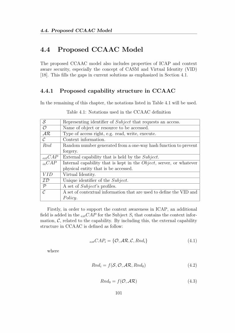
4.4. Proposed CCAAC Model
4.4 Proposed CCAAC Model
The proposed CCAAC model also includes properties of ICAP and contextaware security, especially the concept of CASM and Virtual Identity (VID)[18]. This fills the gaps in current solutions as emphasized in Section 4.1.
4.4.1 Proposed capability structure in CCAAC
In the remaining of this chapter, the notations listed in Table 4.1 will be used.
Table 4.1: Notations used in the CCAAC definition
S Representing identifier of Subject that requests an access.O Name of object or resource to be accessed.AR Type of access right, e.g. read, write, execute.C Context information.Rnd Random number generated from a one-way hash function to prevent
forgery.
extCAP External capability that is held by the Subject.
inCAP Internal capability that is kept in the Object, server, or whateverphysical entity that is be accessed.
V ID Virtual Identity.ID Unique identifier of the Subject.P A set of Subject’s profiles.C A set of contextual information that are used to define the VID and
Policy.
Firstly, in order to support the context awareness in ICAP, an additionalfield is added in the extCAP for the Subject Si that contains the context infor-mation, C, related to the capability. By including this, the external capabilitystructure in CCAAC is defined as follow:
extCAPi = {O,AR, C, Rndi} (4.1)
where
Rndi = f(S,O,AR, Rnd0) (4.2)
Rnd0 = f(O,AR) (4.3)
101

Chapter 4
The internal capability (inCAP ) that creates a pair with the extCAP whichis stored in the object itself or an entity that has higher ”authority” over theobject (e.g. in hierarchical type of network), is defined as follows:
inCAP = {O, Rnd0} (4.4)
where Rnd0 is defined exactly as in Equation 4.3.
4.4.2 Basic definitions
The important definitions used in CCAAC are presented in this section inwhich PN is the targeted platform.
4.4.2.1 Contexts
The Contexts C, that are used to define the VID and Policy is essentially aset of contexts (CSet) with different types (CType). The type of context can bea concrete property such as time or location, but also security related contextsuch as authentication and trust level. In order to apply the context in theaccess control decision, each of the context types has to be evaluated with acertain constraint (CConst).
The overall context definition in CCAAC can be expressed with the follow-ing notation:
CType ∈ {authLevel, trustLevel, time, location, · · · } (4.5)
CSet = {CType(1), CType(2), · · · , CType(n)} (4.6)
CConst := ⟨CType⟩⟨OP ⟩⟨V ALUE⟩ (4.7)
where OP is a logical operator, i.e. OP ∈ {>,≥, <,≤,=, =} and V ALUE isa specific value of CType. Finally, we defined C as a set of context constraintCConst as follows:
C = {CConst(1), CConst(2), · · · , CConst(n)} (4.8)
102
4.4. Proposed CCAAC Model
4.4.2.2 Policy
A policy is associated with certain VID(s) that describes VID(s) preferencesupon allowing other entities to access them. Please note that the entity orsubject requesting access is described by its profile, e.g. subject’s attributes, inthe policy. A policy in the proposed CCAAC model holds an important role inaccess control decision as well as any process involving capability creation anddelegation. Hence, it can simply be defined as a set of rules with parametersrelated to the user as follows:
Policy ∈ {P , C,AR} (4.9)
It is important to note that since a Policy is linked with a VID, and a VIDitself is already linked with an Object, therefore the Object O notation is notincluded in the Policy statement. Furthermore, unlike the definition of theVID, the P and C that are included in the Policy statement are related to theSubject S who tries to access the Object O.
4.4.2.3 VID
An entity, i.e. subject or object, may have more than one identity, namely onemain identity and numbers as other alias identities; this is referred as VID.A VID consists of a user identifier and a set of disclosure policies where thesame disclosure policy can apply to different VIDs. Therefore, the relation-ship between VIDs and disclosure policies is a many-to-many, which can beimplemented using a pointer or hash map.
A VID is also attached with a particular context as well as profile infor-mation of the corresponding user [18] and it can be assumed that the profileinformation can be pre-defined as a set of default profiles or customized to aspecific VID. The profile is assumed to have an one-to-one relationship withthe VID and, for the context, to have a many-to-many relationship with theVID.
Based on these relationships and assumptions, the VID is defined as follow:
V ID ∈ {ID,P, C, Policies} (4.10)
The Profile P in VID may consist of Objects’ O attributes and personalinformation. C refers to Contexts that can be a security context, such as trust
103

Chapter 4
level, authentication level as well as other common contexts such as time andlocation (see Subsection 4.4.2.1). The ID is a unique identifier that can beacquired through cryptographic operations. The Policies is a set of Policythat was explained in 4.4.2.2.
From the practical point of view, the ”attributes” attached with the VID,Policies, P , and C do not necessarily need to be physically contained within theVID itself. The VID could for instance contain just the pointers to the relevantPolicies or Profile, and be implemented using overlay DHT approach thatis commonly used for sharing the information in the P2P or ad-hoc networksin a distributed manner. Nevertheless, the practical implementation of theVID as well as the networking and communication protocols used among thecommunicating entities are outside the scope of this chapter.
4.4.2.4 Other definitions
Other definitions that are used in the formal specification of CCAAC are asfollows:
P = {Profile1, P rofile2, · · · , P rofilen} (4.11)
Policies = {Policy1, Policy2, · · · , Policyn} (4.12)
AR ∈ {Read,Write,NULL} (4.13)
Please note that P is a set of entity’s Profile contained in the V ID, andis stored in the Profiles Repository. The same goes for Policies, it is a set ofany entity’s Policy and is stored in the Policies Repository. The usage of bothProfiles and Policies Repository will be shown when the detail mechanisms ofCCAAC will be explained in the next sub section. As for the AR, it can eitherbe {Read}, {Write}, {Read,Write}, or {NULL}. If AR = {NULL}, thepermission to access a particular object is not allowed.
4.5 Specification of CCAAC Mechanisms
In the following, the formal specification for two of the four main processesin the CCAAC secure access control mechanism is given in details, i.e. thecapability creation and access. The specification assumes that CASM is usedand the message exchanges among the internal modules are as depicted inFigure 4.1. In the proposed CCAAC model, the SDP is not only acting asa central point for security decisions as was the case in CASM, but is alsoresponsible of performing other functionalities as explained in the following.
104

4.5. Specification of CCAAC Mechanisms
Si SDPProfiles
Repository
Policies
Repository
Access
List
Req(VIDi)Map VIDi
with profiles
(1)(2)
Check the policy
of returned profiles
(3)
Relevant policies
(4)
extCAP or
Rejection
(5)
Report
(6)
CAP creation
decision
Add new
Access List
CASM
Figure 4.3: Capability creation protocol in the proposed access control mech-anism
4.5.1 Creation
The capability creation protocol in the proposed access control mechanism ispresented in Figure 4.3 and can be explained as follows:
1. The Subject (S) sends a capability creation request of a certain Object(O) along with its own VID (V IDS) and the VID of the O (V IDO) tobe accessed are sent by S to the SDP. As discussed earlier, S accesses Oaccording the V IDO that can be ”seen” by the O. Whereas the V IDS
will be used later by the O to obtain P and C related to S later on.
2. Upon receiving this request, the SDP asks the Profiles Repository to mapthe profiles of S given its V IDS. This process will return the Profile Pof S.
3. The returned Profile P , together with C, are sent to the Policies Reposi-tory, to check the relevant Policies of the corresponding ObjectO (basedon its V IDO).
4. The Policies repository gets all relevant Policies from the given P andC of the O of interests represented by its V IDO, and then gives them tothe SDP.
5. The SDP combines the received policies with a policy combining algo-rithm and comes up with a decision whether to create a new capability(CAP) for S or not. In case of positive decision, the SDP creates internalcapability of the object (inCAP ) and stores it in the CASM, as well ascreating extCAP for the S and then sends it away. In case of negativedecision, rejection message will be sent to S instead.
105
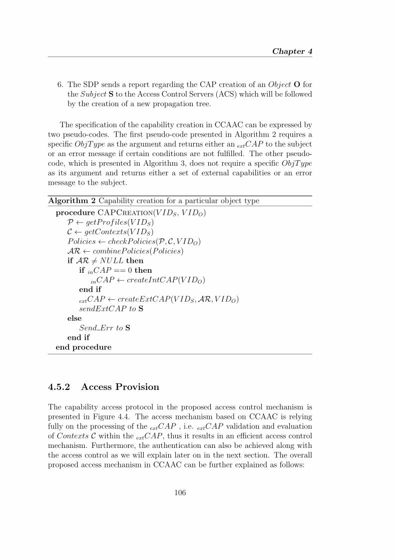
Chapter 4
6. The SDP sends a report regarding the CAP creation of an Object O forthe Subject S to the Access Control Servers (ACS) which will be followedby the creation of a new propagation tree.
The specification of the capability creation in CCAAC can be expressed bytwo pseudo-codes. The first pseudo-code presented in Algorithm 2 requires aspecific ObjType as the argument and returns either an extCAP to the subjector an error message if certain conditions are not fulfilled. The other pseudo-code, which is presented in Algorithm 3, does not require a specific ObjTypeas its argument and returns either a set of external capabilities or an errormessage to the subject.
Algorithm 2 Capability creation for a particular object type
procedure CAPCreation(V IDS, V IDO)P ← getProfiles(V IDS)C ← getContexts(V IDS)Policies← checkPolicies(P , C, V IDO)AR ← combinePolicies(Policies)if AR = NULL then
if inCAP == 0 then
inCAP ← createIntCAP (V IDO)end if
extCAP ← createExtCAP (V IDS,AR, V IDO)sendExtCAP to S
elseSend Err to S
end ifend procedure
4.5.2 Access Provision
The capability access protocol in the proposed access control mechanism ispresented in Figure 4.4. The access mechanism based on CCAAC is relyingfully on the processing of the extCAP , i.e. extCAP validation and evaluationof Contexts C within the extCAP , thus it results in an efficient access controlmechanism. Furthermore, the authentication can also be achieved along withthe access control as we will explain later on in the next section. The overallproposed access mechanism in CCAAC can be further explained as follows:
106
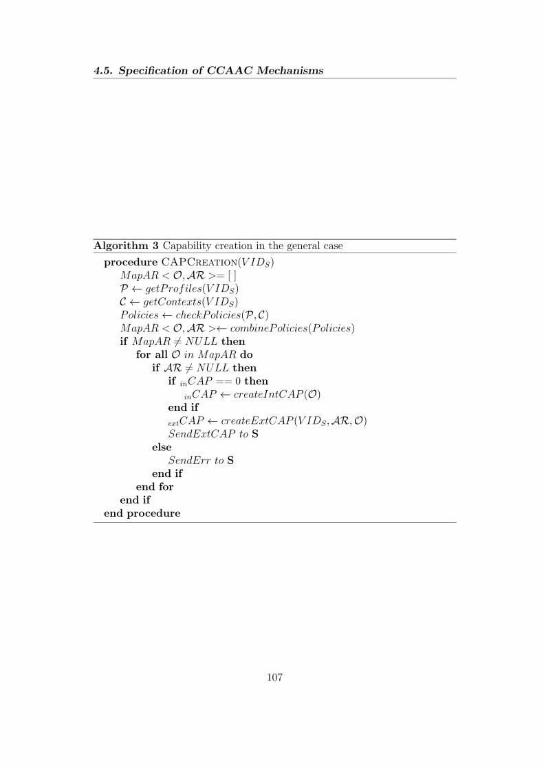
4.5. Specification of CCAAC Mechanisms
Algorithm 3 Capability creation in the general case
procedure CAPCreation(V IDS)MapAR < O,AR >= [ ]P ← getProfiles(V IDS)C ← getContexts(V IDS)Policies← checkPolicies(P , C)MapAR < O,AR >← combinePolicies(Policies)if MapAR = NULL then
for all O in MapAR doif AR = NULL then
if inCAP == 0 then
inCAP ← createIntCAP (O)end if
extCAP ← createExtCAP (V IDS,AR,O)SendExtCAP to S
elseSendErr to S
end ifend for
end ifend procedure
107

Chapter 4
1. The Subject S presents its extCAPS and V IDS to the SDP upon accessrequest.
2. SDP checks the validity of the extCAPS by running a one-way hash func-tion f(S,O,AR, Rnd0) and the compare its result with Rndi within the
extCAPS.
3. In case of a valid extCAPS being received, SDP will then evaluate a seriesof CConst which are contained within the C.
4. The evaluation will return true if all the conditions in all of the CConst
are met, otherwise it will return false.
5. The access request response will finally sent back to S.
The extCAP validation (step (2) in Figure 4.4) is done by comparing thereceived Rndi within the extCAP with the calculated Rndi by means of a one-way hash function f(S,O,AR, Rnd0). The most important components inthe hash function of Rndi to be highlighted are the S and Rnd0. The S canbe obtained from the S within the submitted V IDS and the Rnd0 is obtainedfrom the inCAP that is stored within the O itself. A secure access controlagainst eavesdropping or replay attacks can be ensured by inserting a noncewithin the Rnd0 as will be shown in Section 4.7.
After the extCAP validation is successfully done, the actual contextualinformation will be evaluated against Contexts C within extCAP (step (3) inFigure 4.4). It is assumed that the O, i.e. device, is able to obtained the actualcontextual information from the environment, e.g. sensors or time of access,or by means of messaging mechanisms.
Si SDP
Req(VIDi,extCAPi)
(1)
Access decision
result
(5)
(3) Contexts evaluation
(2) Validate CAP
CASM
(4) Access decision
Figure 4.4: Capability access protocol in the proposed access control mecha-nism
The specification of the access mechanism in CCAAC can be expressed asin the pseudo-code presented in Algorithm 4.
108

4.6. Secure CCAAC based Delegation Framework
Algorithm 4 Access control with external capability
procedure Access(V IDS, extCAP )AR′ = [ ]Rnd′i = f(S,O,AR, Rnd0)if (Rnd′i! = Rndi) then
SendErr to Selse
CtxEval = truefor all CConst in C do
CtxEval = CtxEval ∩ CConst
if CtxEval thenAR′ = AR
elseAR′ = NULL
end ifend for
end ifend procedure
4.6 Secure CCAAC based Delegation Frame-
work
4.6.1 High level delegation model
To support a federation network in IoT, it is necessary to have an establishedtrust relationships prior to the authority delegation of all the entities involvedin this process. The existing solutions in [18] allow all Federation members(in the context of PN) to mutually authenticate to each other, thus establish-ing trust relationships, by means of key management and security associationsmechanisms. By using the similar approach in the context of federated IoT,it is assumed that the trust relationships have been established in all entitiesjoining the federation when it is formed and any new cluster join that fed-eration. Based on this assumption, the proposed high level delegation modelcan be illustrated as in Figure 4.5. In this figure, Delegator is an entity thatdelegates some or all of its authority to another entity, while delegatee is anentity that receives an authority delegation from the delegator. According tothe first motivating scenario stated in 4.3.2, the user’s private device that hasthe authority to access the information from the smart-fridge is the delegator
109
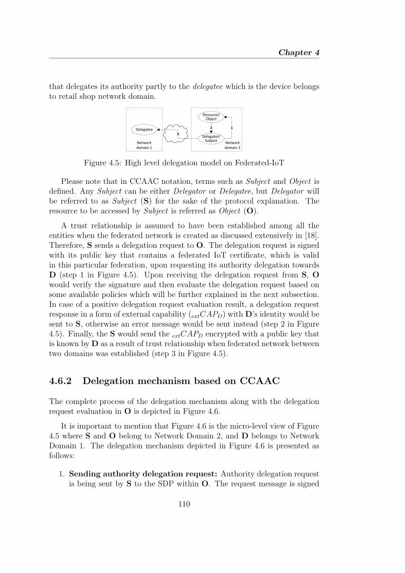
Chapter 4
that delegates its authority partly to the delegatee which is the device belongsto retail shop network domain.
Network
domain 1
Network
domain 2
Delegator/Subject
Resource/Object
Delegatee 2 1
3
Figure 4.5: High level delegation model on Federated-IoT
Please note that in CCAAC notation, terms such as Subject and Object isdefined. Any Subject can be either Delegator or Delegatee, but Delegator willbe referred to as Subject (S) for the sake of the protocol explanation. Theresource to be accessed by Subject is referred as Object (O).
A trust relationship is assumed to have been established among all theentities when the federated network is created as discussed extensively in [18].Therefore, S sends a delegation request to O. The delegation request is signedwith its public key that contains a federated IoT certificate, which is validin this particular federation, upon requesting its authority delegation towardsD (step 1 in Figure 4.5). Upon receiving the delegation request from S, Owould verify the signature and then evaluate the delegation request based onsome available policies which will be further explained in the next subsection.In case of a positive delegation request evaluation result, a delegation requestresponse in a form of external capability (extCAPD) with D’s identity would besent to S, otherwise an error message would be sent instead (step 2 in Figure4.5). Finally, the S would send the extCAPD encrypted with a public key thatis known byD as a result of trust relationship when federated network betweentwo domains was established (step 3 in Figure 4.5).
4.6.2 Delegation mechanism based on CCAAC
The complete process of the delegation mechanism along with the delegationrequest evaluation in O is depicted in Figure 4.6.
It is important to mention that Figure 4.6 is the micro-level view of Figure4.5 where S and O belong to Network Domain 2, and D belongs to NetworkDomain 1. The delegation mechanism depicted in Figure 4.6 is presented asfollows:
1. Sending authority delegation request: Authority delegation requestis being sent by S to the SDP within O. The request message is signed
110

4.6. Secure CCAAC based Delegation Framework
S SDPProfiles
Repository
Policies
Repository
Access
List
Sign{Req(VIDj)}
Map VIDi
with profiles
(1)
(2a)
Check the policy
of returned profiles
(3)
Relevant policies
(4)
extCAP or
Rejection
(5)
Report
(6)delegation
decision Add new
Access List
D
Validate
Signature
Error
if sign invalid
(2b)
CASM in Object
Send delegation statement
(7)
Figure 4.6: Capability propagation protocol for authority delegation in ourproposed access control
with S’s public that contains a Federated IoT certificate so that O isable to make sure the message is indeed sent by S and the integrity ismaintained. Please note that the type of public key and the specificencryption algorithm being used are not within the scope of this work.
2. Mapping the V IDD to Profile: The SDP checks the message’s signa-ture. If the signature is valid, the SDP then asks VID-Profiles mappingbox to map the profiles of D given V IDD. It will return the profile ofD.
3. Check the relevant policies: The returned Profiles P , together withthe C and V IDO, are then sent to the Policies Repository, to check thedisclosure policies of the corresponding Object (based on its VID).
4. Return the relevant policies: The Policies Repository gets all therelevant policies from the given P and C of the object or resource ofinterest represented by its V IDO, and then gives them to the SDP.
5. Delegation decision: The SDP combines the received policies with apolicy-combining algorithm and comes up with a decision whether toapprove the authority delegation by creating a new capability (CAP) forD or not. In the case of a positive decision, the SDP creates a delegationstatement in the form of extCAP for the D and then sends it to S. Thedifference between the newly created extCAP and the one that is ownedby the S, lies in the D’s identifier D within the Rndi component. In thecase of a negative decision, a rejection message will be sent to S instead.
6. Update propagation tree: In parallel to sending the delegation deci-sion, the SDP sends a report regarding the CAP creation of an object
111

Chapter 4
for Subject i, Si, to the ACS which will be followed by the creation of anew propagation tree.
7. Sending authority delegation statement: Finally, S sends the au-thority delegation statement in the form of extCAP particularly for D.Moreover, in order to maintain the confidentiality and integrity of the
extCAP , it can be signed with a shared secret key between S and D,based on an assumption that both domains have established a trust re-lationship by authenticating each other through a certain key pair.
Steps 2 through 5 is expressed in the pseudo-code in Algorithm 5.
Algorithm 5 Capability delegation decision
procedure delegateCAP(V IDD, V IDO)P ← getProfiles(V IDD)C ← getContexts(V IDD)Policies← checkPolicies(P , C, V IDO)decision← combinePolicies(Policies)if decision = NULL then
if IntCAP = 0 then
inCAP ← createIntCAP (V IDO)end if
extCAP ← createExtCAP (V IDD,AR, V IDO)end if
end procedure
It is assumed that S as the delegator knows the identity of the O and D.This is possible when the delegator S, subscribes to a service, in which a devicein the service provider’s domain needs to be given an authority delegation, i.e.as delegatee D, in order to access a device or resource within the delegator ’snetwork domain, i.e. O. With this assumption, S needs to submit a delega-tion request by stating the identities of D and O in the form of V IDD andV IDO, respectively. Once submitted, delegatee’s Profile (P) and Context (C)can be obtained from V IDD as they are attached to it (see Equation 4.10).Afterwards, all relevant policies related to V IDO that contain delegatee’s Pand C are gathered from the Policies Repository to be further evaluated by acertain Policies Combining Algorithm to obtain a delegation decision.
112

4.7. Evaluation and analysis
4.7 Evaluation and analysis
The evaluation will focus on secure capability creation and access mechanismsas the most important processes in the access control, especially when capa-bility is involved. In order to secure the access control mechanism, simplemechanisms of generating nonce in both sides and a secret key cryptographyto encrypt the message are introduced. The Automated Validation of InternetSecurity Protocols and Applications (AVISPA) tool [12] which is based on theDolev-Yao [4] model is used for model verification purposes as well as for eval-uating the secrecy and authentication between the subject, i.e. the one thatrequests access, and the object, i.e. the one that is being accessed.
4.7.1 Evaluation procedure
In order to carry out the evaluation using AVISPA, the following assumptionsare made:
• Both Subject and Object have already obtained shared key(s), i.e. eithersymmetric or asymmetric, through key generation and sharing mecha-nisms prior to the capability creation process.
• To prevent a replay attack, a nonce is incorporated within the Rnd0 of
inCAP and extCAP .
• A new key, which is a result of a one-way hash function using noncegenerated by both parties, is presented by S that wants to access O.
• The access mechanism using external capability is used immediately afterthe capability creation in order to have an integrated evaluation of bothmechanisms.
The complete protocol evaluation is presented in the following model:
S→ O: {S.Req.Ns} Kso
S← O: {S.Oxo.ARs.Cs.No.Rndi} Kso
S→ O: {S.Oxo.ARs.Cs.Rndi} KN
where
• S: Subject identifier.
• O: Object identifier.
• { } : A symbol of encryption.
113

Chapter 4
• Req: A capability creation request message.
• Ns: A nonce generated by S.
• No: A nonce generated by O.
• Kso: A shared secret key shared by the S and O prior to the capabilitycreation process to encrypt the whole message.
• KN : A new shared secret key generated by the S as a result of a one-wayhash function, f(Ns.No).
• Rndi: A result of a one-way hash function f(S.Oxb.ARs.Cs.Rnd0).
• Rnd0: A result of a one-way hash function f(Oxb.ARs.No).
Besides the protocol that involves S and O, an intruder, I, based on Dolev-Yao intruder model has been introduced in the evaluation. The intruder I isassumed to have the knowledge of the following:
• S: the Subject’s identifier.
• Ksi: the shared secret key between S and I.
• Kio: the shared secret key between I and O.
• all the hash functions being used in the protocol, i.e. f(Ns.No), f(S.Oxo.ARs.Cs.Rnd0),and f(Oxo.ARs.No).
The goal of the evaluation is to verify the secrecy of the new generated keypresented by S, e.g. KN , in order to access O, and the No generated by O inorder to create Rnd0. Furthermore, No is also used to authenticate S over O.These two important aspects in the evaluation will be discussed further in thecoming subsections.
4.7.2 The secrecy
The secrecy of No is an important component to prevent replay attacks on the
extCAP that is submitted by S. The evaluation result using the AVISPA toolshows that the secrecy of No is kept. It is important to note that the Dolev-Yao intruder model used in the evaluation is assumed to have knowledge ofSubject’s identifier S, the hash functions being used, and the shared keys, Ksi
and Kio. The intruder cannot decrypt the message being sent by either sideeven if he can capture it since he has no knowledge of Kso. In other words, theknowledge of Ksi and Kio that might be used by the intruder to fool both sides
114
4.8. Conclusion
will be useless in this case. As a result, both nonce, i.e. Ns and No, remainsecret. Secondly, the secrecy of KN which is a result of simple one-way hashfunction f(Ns.No) as presented in the evaluation model is another importantfact to be evaluated. Similar with the No, the evaluation result by AVISPAtool also shows that KN remains secret. As explained previously, the secrecy ofKN is a result of the secrecy of both Ns and No due to inability of the intruderto decrypt the message without having the knowledge of Kso. Based on thisevaluation result, i.e. the fact that KN remains secret, it could be concludedthat the extCAP is safe from eavesdropping and replay attacks.
4.7.3 The authentication
The authentication of S against O can be achieved when O receives a validRndi. In particular, the received No within the Rndi, which is supposed to bea secret nonce generated by O and known only by S, has to be valid and keptsecret. The evaluation result by AVISPA tool shows that authentication isachieved as well. As stated previously in the secrecy analysis, the fact that thesecrecy of No that can be ensured in the protocol results in the validity of Rndiwithin the extCAP , thus S can successfully authenticated by O. Furthermore,this result also shows that the proposed CCAAC model is not only able toprovide access control but also authentication at the same time. Hence, themain objective of providing security mechanisms, i.e. authentication and accesscontrol, in order to prevent security threats, especially in the context of IoT,has been achieved.
4.8 Conclusion
Access control is of paramount importance for a full thrive of IoT, especiallydue to the dynamic network topology and distributed nature. In this chap-ter, different access control models with their advantages and limitations havebeen discussed. Based on this, the secure CCAAC model with specificationsof the capability (CAP) creation and access mechanisms has been proposed.The definition of Federated IoT is used as a baseline in designing the proposedauthority delegation mechanism that is part of the overall CCAAC model. Theprotocol description and security consideration involving the usage of crypto-graphic keys are further presented in the chapter to give some guidelines inthe practical implementation. The proposed CCAAC has been analysed in thepresence of security threats, such as eavesdropping and replay attack by an in-truder, in order to test its resilience. Security proofs and evaluations by using
115
Chapter 4
AVISPA tool show that the CCAAC model achieves not only access controlbut also the secrecy of CAP and authentication.
The are several works remain to be done in this research area. First, in-corporating the CCAAC model with light-weight authentication supportingcapability, such as the one proposed in [17], and to evaluate it with a morerealistic adversaries model. Second, the current authority delegation frame-work in the proposed CCAAC assumes trust relationships that are alreadyestablished among entities in different federation domain. The future outlookwill consider the case in which no prior knowledge of the trust relationshipbetween two network domains in Federated IoT. Unlike the approach used inthis chapter, an additional entity that is trusted by both domains, for instanceIdentity Provider (IdP), needs to be involved in the design. Lastly, prototypeimplementation of all aspects in CCAAC by using the existing access controlrealization model or on a device level will be something to look forward.
116

4.9. References
4.9 References
[1] Bayu Anggorojati, Parikshit N. Mahalle, Neeli R. Prasad, and RamjeePrasad. Capability-based access control delegation model on the federatediot network. InWireless Personal Multimedia Communications (WPMC),2012 15th International Symposium on, September 2012.
[2] Tuomo Repo Arto Hamalainen, Jari Porras and Pekka Jappinen. Apply-ing wireless technology to access control systems. In 1st Workshop onApplications of Wireless Communications (WAWC’03), 2003.
[3] Tyler Close. Acls don’t. Technical report, Hewlett Packard Laboratories,2009.
[4] D. Dolev and A. Yao. On the security of public key protocols. InformationTheory, IEEE Transactions on, 29(2):198 – 208, mar 1983.
[5] Patrik Floreen, Michael Przybilski, Petteri Nurmi, Johan Koolwaaij,Anthony Tarlano, Matthias Wagner, Marko Luther, Fabien Bataille,Matthieu Boussard, Bernd Mrohs, and Sian Lun Lau. Towards a contextmanagement framework for mobilife. In IST Mobile & CommunicationsSummit, 2005.
[6] H. Gomi. Dynamic identity delegation using access tokens in federatedenvironments. In Web Services (ICWS), 2011 IEEE International Con-ference on, pages 612 –619, july 2011.
[7] Hidehito Gomi, Makoto Hatakeyama, Shigeru Hosono, and Satoru Fujita.A delegation framework for federated identity management. In Proceedingsof the 2005 workshop on Digital identity management, DIM ’05, pages 94–103. ACM, 2005.
[8] L. Gong. A secure identity-based capability system. In Security andPrivacy, 1989. Proceedings., 1989 IEEE Symposium on, pages 56 –63,may 1989.
[9] M. Grossmann, M. Bauer, N. Honle, U.-P. Kappeler, D. Nicklas, andT. Schwarz. Efficiently managing context information for large-scale sce-narios. In Pervasive Computing and Communications, 2005. PerCom2005. Third IEEE International Conference on, pages 331 –340, march2005.
[10] K. Hasebe and M. Mabuchi. Capability-role-based delegation in workflowsystems. In Embedded and Ubiquitous Computing (EUC), 2010 IEEE/I-FIP 8th International Conference on, pages 711 –717, dec. 2010.
117

Chapter 4
[11] Koji Hasebe, Mitsuhiro Mabuchi, and Akira Matsushita. Capability-baseddelegation model in rbac. In Proceeding of the 15th ACM symposium onAccess control models and technologies, SACMAT ’10, pages 109–118, NewYork, NY, USA, 2010. ACM.
[12] http://avispa project.org/.
[13] Young-Gab Kim, Chang-Joo Mon, Dongwon Jeong, Jeong-Oog Lee, Chee-Yang Song, and Doo-Kwon Baik. Context-aware access control mechanismfor ubiquitous applications. In Piotr Szczepaniak, Janusz Kacprzyk, andAdam Niewiadomski, editors, Advances in Web Intelligence, volume 3528of Lecture Notes in Computer Science, pages 932–935. Springer Berlin /Heidelberg, 2005.
[14] Devdatta Kulkarni and Anand Tripathi. Context-aware role-based ac-cess control in pervasive computing systems. In Proceedings of the 13thACM symposium on Access control models and technologies, SACMAT’08, pages 113–122, New York, NY, USA, 2008. ACM.
[15] Henry M. Levy. Capability-Based Computer Systems. Butterworth-Heinemann, 1984.
[16] Sue Long, Rob Kooper, Gregory D. Abowd, and Christopher G. Atkeson.Rapid prototyping of mobile context-aware applications: the cyberguidecase study. In Proceedings of the 2nd annual international conferenceon Mobile computing and networking, MobiCom ’96, pages 97–107, NewYork, NY, USA, 1996. ACM.
[17] Parikshit N. Mahalle, Bayu Anggorojati, Neeli R. Prasad, and RamjeePrasad. Identity establishment and capability based access control (iecac)scheme for internet of things. In Wireless Personal Multimedia Commu-nications (WPMC), 15th International Symposium on, September 2012.
[18] R. Prasad. My personal Adaptive Global NET (MAGNET). Signals andCommunication Technology Book. Springer Netherlands, 2010.
118

5Capability-based access control in theM2M local cloud platform: A practical
implementation perspective
Protection and access control to resources plays a critical role in a distributedcomputing system like M2M and cloud platform. The M2M local cloud plat-form considered in this paper, consists of multiple distributed M2M gatewaysthat form a local cloud – presenting a unique challenge to the existing accesscontrol systems. The most prominent access control systems, such as ACLand RBAC, lack in scalability and flexibility to manage access from users orentity that belong to different authorization domains, and thus unsuitable forthe presented platform. The access control approach based on API keys andOAuth that is used by the existing M2M Cloud platform, fails to provide finegrained and flexible access right delegation at the same time when both meth-ods are used together. The proposed approach is built upon capability-basedaccess control that has been specifically designed to provide flexible, yet re-stricted, access rights delegation. A number of use cases are provided to showthe usage of capability creation, delegation, and access provision, particularlyin the way application accesses services provided by the platform.
119

Chapter 5
5.1 Introduction
The concern about security and privacy play a huge role for mass adoption ofthe IoT/M2M as cloud services [8]. More specifically, access control to infor-mation and resources is very critical to ensure security and privacy of a system.The M2M local cloud platform is a platform that consists of distributed M2Mgateways that forms a cloud locally and provides M2M services collectively.Consequently, some unique challenges in access control is imposed, especiallyin the scalability and flexibility aspects.
ACL is the most common way of providing access control, but it becomesmore and more complex as the number of subjects and resources increases.The RBAC [9] is introduced to cope with this issue, by mapping subjects intoroles. Many access control models are also derived based on RBAC model.However, it cannot cope with the problems of role explosion and multi admin-istrative domains. The ABAC system tries to solve the roles explosion issueby specifying access policies and rules based on the attributes of the subjectsand resources, thus potentially reducing the number of rules. However, defin-ing a consistent attributes is not an easy task, especially in the M2M worldwhere the context is highly dynamic. Overall, all previously mentioned accesscontrol mechanisms have a common problem which is difficulties in enforcingleast privilege access principle and scalability problem which is a major re-quirements in M2M. Additionally, they do not provide flexible access rightsdelegation feature.
One of the existing IoT/M2M Cloud platform, Xively, relies on the typicalaccess control solution in many cloud services. The API keys can be createdfor the devices, client applications, and actual users to authorize the access ofspecific resource in Xively [10]. However, this API key is managed centrally inXively cloud platform and is not delegable. On the other hand, OAuth [7] isimplemented in Xively to allow access of third party application to resourcesowned by a user. However, using the API key in the OAuth application wouldmean granting access to all resources tied with the application to the thirdparty.
A capability-based access control have been seen as a promising solutionto problems in IoT/M2M by some recent research works, but its actual imple-mentation is still a big challenge. The CCAAC presented in Chapter 4, triesto solve the above mentioned issues in the context of IoT using the capability-based access control, but the use of access policy based on VID is not clearand quite impractical to be implemented. Additionally, the attempt to highlycontrol the capability propagation significantly reduce the flexibility of access
120

5.2. System Description
right delegation. Another capability-based access control in IoT has been donein [4] in which the rights delegation and revocation based on capability havebeen emphasized. However, it does not explain how the capability is requestedand granted, which is the most important part especially in the IoT and M2Mworld. The proposed solution is built upon capability-based access controldesigned to provide flexible, yet restricted, access rights delegation.
The rest of this chapter is organized as follows: An overview of the M2Mlocal cloud platform architecture and the way applications access the platformis described in Section 5.2. The detail of the proposed approach is presented inSection 5.3. Some use cases explaining how the proposed approach is appliedin the real platform is explained in Section 5.4. Finally, the conclusion andfuture outlooks are given in Section 5.5.
5.2 System Description
Different approach in the IoT or M2M architectures, as reported in [8], willimpact the security challenges and their solutions. As the access control mech-anism presented in this paper is particularly designed and developed for theM2M local cloud platform within the European FP7 BETaaS (Building theEnvironment for the Things as a Service) project, thus it is necessary to ful-fil the unique technical requirements and architecture of this platform. Thissection is dedicated to explain the BETaaS platform’s architecture, and themechanism in which the applications and users can access the services pro-vided by BETaaS platform. It is important to note that although the accesscontrol mechanism is designed and developed for BETaaS project, it is alsoapplicable to other platforms, especially the M2M and Cloud platforms.
5.2.1 BETaaS architecture
BETaaS is a content-centric platform distributed over a local cloud, hosted bygateways, providing an environment for applications accessing M2M servicesand devices through a set of services [6]. In principle, the platform consistsof multiple distributed M2M gateways (GW)s that are collaborating to eachother and forming a so called local cloud or BETaaS instance. With thisapproach, there can exist different BETaaS instances which do not necessarilyconnected to each other. This approach is totally different than the typicalM2M deployment where the cloud is hosted in a centralized cloud provider.
121

Chapter 5
TaaS local
component
BETaaS GW 1
ETSI M2M
adaptation layer
M2M
Implementation
(ETSI M2M)
Service
TaaS local
component
CoAP M2M
adaptation layer
TaaS local
component
M2M
Implementation
(CoAP)
BETaaS GW 2 BETaaS GW 3
Ta
aS
PH
Y l
ay
er
Lo
gic
al
lay
er
Se
rvic
e l
ay
er BETaaS Instance/Local Cloud
Figure 5.1: High level architecture of the BETaaS platform
The high level architecture of BETaaS platform consists of three layers:Service layer, Logical layer, and Physical layer, as illustrated in Fig. 6.1. Onthe practical deployment perspective, the main functionality of the platformresides in the logical and service layers, which are implemented in a GW. Itis important to note that since a GW is implemented in a device more likelyto have very minimum user intervention, the access control mechanism shouldwork in the same manner also.
At the functional architecture point of view, BETaaS consists of severalmanagers that perform different functionalities, one of it is the security man-ager [2]. The layered structure as in the high level architecture is also appliedin the design of the managers, e.g. security manager. The purpose of such de-sign is to allow clear division of security tasks in different layer, e.g. applicationlevel security resides in the service layer, the GW level security is at the Thingas a Service (TaaS) sub-layer, and the adapation sub-layer handles things levelsecurity. Please note that in the context of BETaaS, thing(s) refers to anydevice or object with communication capability, such as sensor, actuator, tag,etc.
5.2.2 Security manager
The security manager consists of some sub-managers, namely Key, Authen-tication, Authorization, and Trust managers, which perform functionalitiesaccording to their respective names. Brief description of each sub-manager
122

5.2. System Description
of the proposed security manager in BETaaS which are closely related to theproposed access control mechanism is presented in the following sub-sections.
5.2.2.1 Key Manager
Key management is a very important functionality which defines how to man-ager the secret (and shared) keys, as the important components to perform anysecurity operation. The key management has a role to manage the associationsof different entities (e.g. GWs with an instance, application with an instance,etc), which will be used to perform authentication, and later on to manageapplication and user sessions as well as to perform encrypted communication.
A common security mechanism to provide trust relies on the PKI in a formof a digital certificate issued by the trusted third party, i.e. CA. In some caseshowever, the BETaaS instance does not have a constant access to the externalCA, e.g. local cloud that is built upon ad-hoc network, the method whichinvolves external CA cannot be directly applied. Therefore, a key managementmechanism that relies on local certificate issued by an internal CA is proposed.
In the context of BETaaS, the internal CA refers to a gateway which actsas a common CA of that particular instance, also known as GW*. At thebeginning of BETaaS instance creation, the GW* would initiate the creationof root and intermediate certificates which forms the root credential of thisparticular instance. For a new GW to join the instance, it needs to generatea key pair, i.e. public and private keys, and then sends a join request to GW*along with the generated public key. Upon receiving join request, GW* wouldcreate a credential for the new GW which includes a certificate generated fromthe public key and other submitted information by the new GW and is signedusing the private key of the GW*’s credential. This new created credentialplays an important role to provide trust relationship among all the GWs withinthe local cloud or instance, including the access control mechanism as well asin deriving key for establishing secure communication between two GWs.
The ECC based PKI is used in the practical implementation of key managerbecause it requires smaller key size compared to other crypto algorithm, suchas RSA, to provide the same level of security. For example, a 160 bit ECC isequivalent to a 1024 RSA, a 192 bit ECC is equivalent to a 1536 bit RSA, a224 bit ECC is equivalent to a 2048 bit RSA and so on. A set of EuropeanCommission (EC) domain parameters recommended by National Institute ofStandards and Technology (NIST) and Standard of Efficient Cryptography(SEC) are chosen in order to generate a key pair of ECC.
123
Chapter 5
5.2.2.2 Authentication Manager
In the context of BETaaS, two level of authentications are considered, namelygateway level authentication and application and service level authentication.
The gateway level authentication mainly deals with the mutual authen-tication in order to establish secure communication between two GWs. Themethod to perform mutual authentication is based on the Elliptic Curve Menezes-Qu-Vanstone (ECMQV) protocol. ECMQV is a three-pass key agreement pro-tocol that has been standardized in ANSI X9.63, IEEE 1363, ZigBee Smart En-ergy 1.0, etc [5]. In principle, it is an extension of the ordinary Diffie-Hellmankey agreement protocol with the ECC. Among the benefits of ECMQV arelower computational complexity and bandwidth reduction. Detail explanationof how ECMQV protocol works can be reviewed in [5].
The application and user level authentication also relies on the ECC basedPKI. But unlike the key management mechanism that relies on local certifi-cate issued by the internal CA, an external CA is used to issue certificate forapplication. The certificate for application is obtained through a registrationprocess and the authentication by means of certificate verification only oc-curs upon application installation in the platform. Further explanation aboutthe application authentication and installation process is presented in Section5.2.3.
5.2.2.3 Authorization Manager
Authorization manager is the central component that performs access controlmechanism in the platform. The detail explanation of how the access controlmechanism within the authorization manager works and how it interacts withother components will be presented in Section 5.3 and 5.4.
5.2.2.4 Trust Manager
In the context of BETaaS, trust represents the level of reliability on a Thing orThing Service to produce certain data and/or perform certain actions, in theexpected conditions. In the end, this is related to the reliability trust, since itis assumed that the system relies on a set of Things in order to execute servicesin BETaaS platform. However, the detail explanation of trust manager is outof the scope of this chapter because it is totally independent with the proposedaccess control mechanism.
124
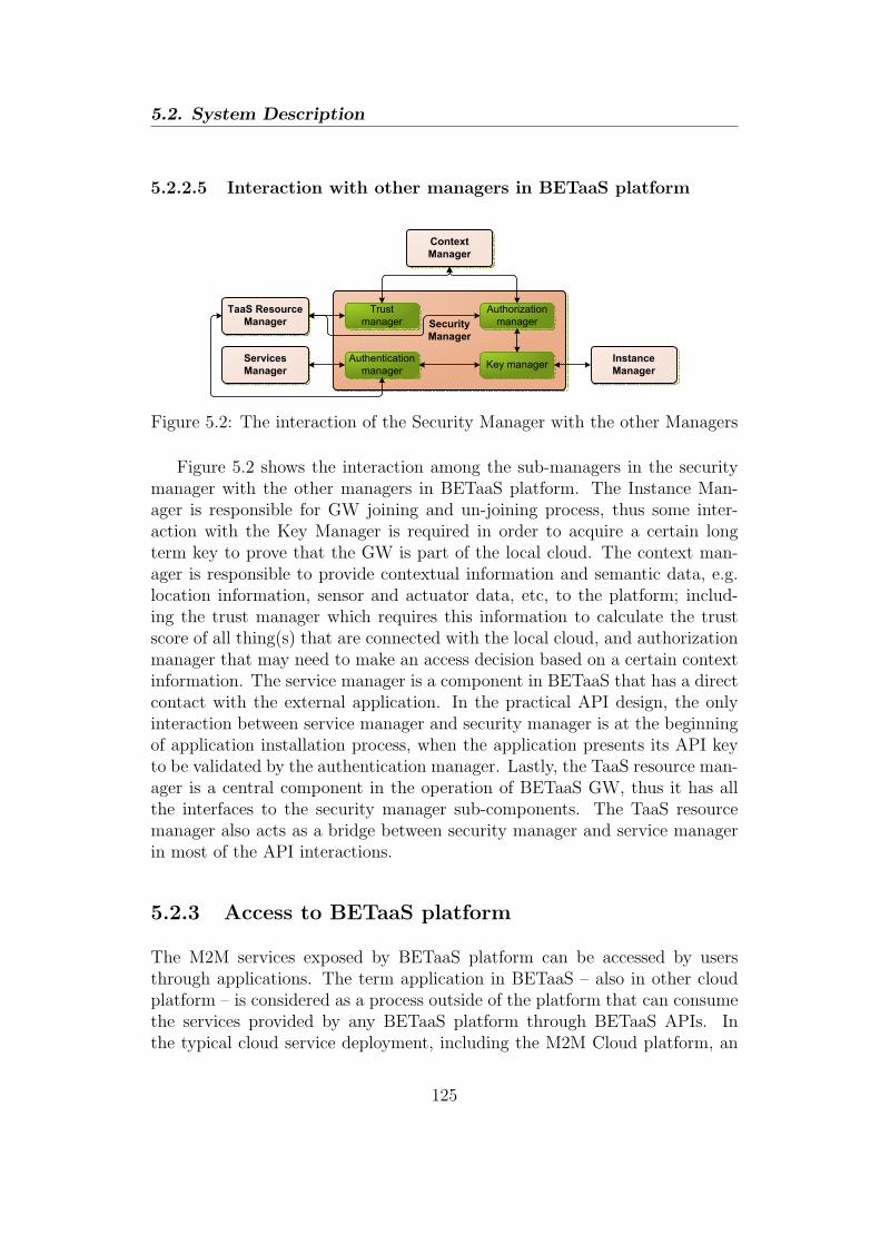
5.2. System Description
5.2.2.5 Interaction with other managers in BETaaS platform
Trust
manager
Key managerAuthentication
manager
Authorization
manager
Context
Manager
Services
Manager
Instance
Manager
TaaS Resource
Manager Security
Manager
Figure 5.2: The interaction of the Security Manager with the other Managers
Figure 5.2 shows the interaction among the sub-managers in the securitymanager with the other managers in BETaaS platform. The Instance Man-ager is responsible for GW joining and un-joining process, thus some inter-action with the Key Manager is required in order to acquire a certain longterm key to prove that the GW is part of the local cloud. The context man-ager is responsible to provide contextual information and semantic data, e.g.location information, sensor and actuator data, etc, to the platform; includ-ing the trust manager which requires this information to calculate the trustscore of all thing(s) that are connected with the local cloud, and authorizationmanager that may need to make an access decision based on a certain contextinformation. The service manager is a component in BETaaS that has a directcontact with the external application. In the practical API design, the onlyinteraction between service manager and security manager is at the beginningof application installation process, when the application presents its API keyto be validated by the authentication manager. Lastly, the TaaS resource man-ager is a central component in the operation of BETaaS GW, thus it has allthe interfaces to the security manager sub-components. The TaaS resourcemanager also acts as a bridge between security manager and service managerin most of the API interactions.
5.2.3 Access to BETaaS platform
The M2M services exposed by BETaaS platform can be accessed by usersthrough applications. The term application in BETaaS – also in other cloudplatform – is considered as a process outside of the platform that can consumethe services provided by any BETaaS platform through BETaaS APIs. Inthe typical cloud service deployment, including the M2M Cloud platform, an
125
Chapter 5
application obtains a set of API keys that allows it to access different set ofservices provided by the Cloud platform. These keys are normally generatedduring the registration process, e.g. the application developer would registerits application in the cloud platform before starting the development process.However, the same approach cannot be applied in BETaaS due to multipleBETaaS instances or local clouds with different owners that may exist in allover the world, while implementing the same sets of APIs.
On the other hand, such a distributed cloud deployment also impacts theway an application accesses different BETaaS platform. For example, thesame intrusion detection application developed for BETaaS platform will notnecessary be able to consume the same service through the same API from aBETaaS instance deployment in the same way as those in the other BETaaSinstances deployment. That is due to the availability of a particular thingservice and other requirements that pertaining to each independent local cloud.To cope with this issue, an installation procedure is needed when an applicationaccesses a BETaaS instance for the first time [2]. The purpose of this procedureis for allocating the resources required for the application according to a set ofrequirements in the local cloud. The authenticity check of the application isalso performed during the application installation. It is based on the typicalPKI where the CA can be any external trusted third party (unlike the keymanagement at the GW level), such as BETaaS application store. However,relying on the authenticity check in the installation procedure and the typicalAPI keys solution are still unable to solve the access control issue, let alone theissues of scalability and flexibility in access rights delegation that are inherentin the existing access control mechanisms, which have been pointed out inSection 5.1.
5.3 The proposed approach
The proposed approach is based on the capability based access control. Someenchancements are made in order to the problems faced by the other capabilitybased access controls. This section explains the overall capability design alongwith the mechanisms involved in the capability based access control.
126

5.3. The proposed approach
5.3.1 Capability design
The proposed capability consists of internal and external capability, e.g. inCAPand extCAP respectively, similar to the basic use of capability in our previ-ous work [1]. In BETaaS’s context, the resource or object is the thing servicewhich is owned by a GW, thus inCAP is created and owned by any GW thatoffers thing services. Thing service refers to a service provided by a thing,e.g. temperature sensing service by a temperature sensor. The extCAP can beobtained by any party that wish to access a resource that corresponds to the
inCAP , including another GW in the local cloud, applications, and users.
The basic structure of inCAP is as follows:
inCAP = {O, DSign}
where
• O: The name of object or resource to be accessed.
• DSign: A digital signature of this inCAP , which is obtained by signingthe hash of the inCAP ’s content, i.e. O, with GW’s private key that isobtained by the key management mechanism in Section 5.2.1. It is usedto check the integrity of the capability’s content.
On the other hand, extCAP contains much more information than the
inCAP which is necessary for the capability delegation and revocation mech-anisms.
extCAP = {I,S,AR,O,VC,R, DSign}
where
• I: The information about the issuer of this extCAP .
• S: The information about the subject or the extCAP holder.
• AR: The details of access rights over the object or resource granted tothe subject.
• O: The name of object or resource to be accessed.
• VC: The validity condition of the extCAP , e.g. validity period.
• R: The URL of the capability revocation service.
127

Chapter 5
• DSign: A digital signature of this extCAP , which is obtained by signingthe hash of the extCAP ’s content with issuer’s private key.
I is a data structure that contains {IssuerType, IssuerCertificate, Issuer-Capabilities}. The IssuerType can either be a GW, application, or user. TheIssuerCertificate is the certificate obtained by a GW upon joining a localcloud, or by an application upon the registration (i.e. before using the APIs ofthe cloud services in the application), or by a user upon the registration (i.e.within the local cloud platform or the individual GW). The IssuerCertificatefield plays an important role in the access delegation because the validity ofa delegated capability depends on the validity of the issuer’s certificate. Inaddition, it is also used to check the validity of the digital signature (DSign)field of this capability. IssuerCapabilities is the chain of capabilities whichshows the access delegation chain that the issuer hold.
S is another data structure that contains {SubjectType, SubjectPublicKey-Info}. Similar to IssuerType, the Subject Type can be a GW, application, oruser. The SubjectPublic KeyInfo is an optional field that gives an informa-tion about the public key of the subject, i.e. capability’s holder.
AR is also a data structure that contains the following field: {AccessType,AccessConditions}. The AccessType is either GET, PUT, POST or DELETE,which is equivalent to Read, Write, Modify or Delete. The AccessConditionsstates some access conditions to be excercised upon granting the access per-mission, which may include some context information.
5.3.2 Capability creation
Initially, the object or resource owner, i.e. GW, creates inCAP s for all theobjects that it have authority over. In BETaaS context, a inCAP is createdwhen a thing that provides thing services is connected to the GW. The extCAPcan then be granted upon request by the external parties that wish to gainaccess to the a resource that coresponds to that particular extCAP .
In principle, the detail mechanism of the extCAP creation is similar tothe capability creation presented in Chapter 4 with the exeption that no VIDis used in this approach. Rather, it uses a digital certificate that contains aGW’s or application’s public key, that is signed by the GW* or by the BETaaSApps’s trusted CA respectively. In addition, a set of access policies is createdand updated by the GW’s owner, thus allowing a fine tuned access that fitsthe needs and requirements of each individual GW in a local cloud.
128

5.3. The proposed approach
5.3.3 Access right delegation mechanism
The access right can be easily delegated by propagating the extCAP , but itis difficult to control its propagation [3]. Some attempts have been made tocontrol the capability delegation in the previous works. Our previous workuses a mechanism where the delegator needs to ask the original resource ownerbefore delegating its extCAP which reduces the flexibility of the access rightsdelegation through capability [1]. On the other hand, [4] tries to control theright delegation by specifying the delegation depth in the access right fieldwithin the capability. However, it is impractical to predict the proper depthof delegation in advance as one can always need to go one more level down.
In the proposed approach, it is assumed that the extCAP is delegable bydefault, i.e. no need to specify the delegable and delegation depth as in [4].Anybody can delegate a subset of its access rights stated in the extCAP bycreating another extCAP , specifying its ID, certificate, and a list of extCAPchain in the issuer field, and sign the extCAP with its own private key. Whenthe delegatee, i.e. the extCAP holder that receives a delegated access, accessesthe resource and presents its extCAP to resource owner for the first time,the resource owner will evaluate the extCAP . The most critical point in theevaluation that controls the access right delegation is by validating the extCAPissuer based on the issuer’s certificate (for GWs and applications) or usercredential (for the registered user in the corresponding GW). If the certificateor credential cannot be validated, it simply means that the issuer has no rightto delegate the extCAP , thus access request is rejected immediately. Otherwise,the extCAP ’s signature is validated based on issuer’s public key to ensure thatthe delegated extCAP has not been tampered either by the delegatee or otherparties. The evaluation also includes all the validity check that is performedin the capability access evaluation (see Section 5.3.4), both for the delegatee’sand the delegator’s extCAP s. The evaluation process also makes sure that theAR and VC specified in the delegatee’s extCAP are the subsets of those in thedelegator’s extCAP . If the extCAP passes all the previously mentioned validitychecks, the resource owner can optionally check the access policies and renewthe delegated access rights. Finally, a new extCAP signed by the resourceowner’s private key will be granted to the delegatee, thus allowing a simplervalidity check as a normal extCAP in the next access time.
In this way, the access right delegation mechanism in the proposed approachallows a more flexible access right delegation as compared to the approach inChapter 4, while providing more control over capability delegation as com-pared to [4], and maintaining a finer-grained access control as compared to theapproach used in [10].
129

Chapter 5
5.3.4 Capability access evaluation
Upon access request by receiving the extCAP , the resource owner validatesthe submitted extCAP by checking its validity period, validating the extCAP ’sDSign, and definitely checking whether the requested access right is listed inthe extCAP . In addition, the resource owner also checks the validity of the
inCAP and/or extCAP which are specified in the IssuerCapabilities field, andwhether or not the extCAP has been revoked through the revocation service.To make it even more secure, the extCAP holder can also sign the extCAP andsubmit it along with its public key information to prove that he/she really isthe extCAP holder, e.g. in case the extCAP is stolen.
5.3.5 Capability revocation
The delegator or extCAP issuer can also revoke a set of extCAP s delegatedearlier for many different reasons, for instance due to maliciousness, stolen
extCAP , etc. In principal, this mechanism is the same as certificate revocation,but it is much simpler since the capability is only used in a single place, i.e.the resource owner. The delegated capability can be revoked by sending acapability revocation request to the URL specified in theR field by mentioningthe extCAP ’s ID and reason of revocation. It is important to mention thereason of revocation because it can determine whether the further delegated
extCAP should be revoked or not.
5.4 Use cases
Some use cases will be presented to show how the proposed capability-basedaccess control work in different operations of the M2M local cloud, e.g. GWjoin to local cloud, application installation, and other delegation cases. Forthe sake of simplicity, the presented use cases only show the security aspects ofthe actual operations, i.e. other aspects like resource allocation, context andQoS evaluations are not completely shown.
5.4.1 GW joining process
In Fig. 5.3, the GW joining process is shown. In this process, the new GWthat wants to join to the local cloud sends a join request to the GW* byincluding its long term public key and some information about it, e.g. user
130
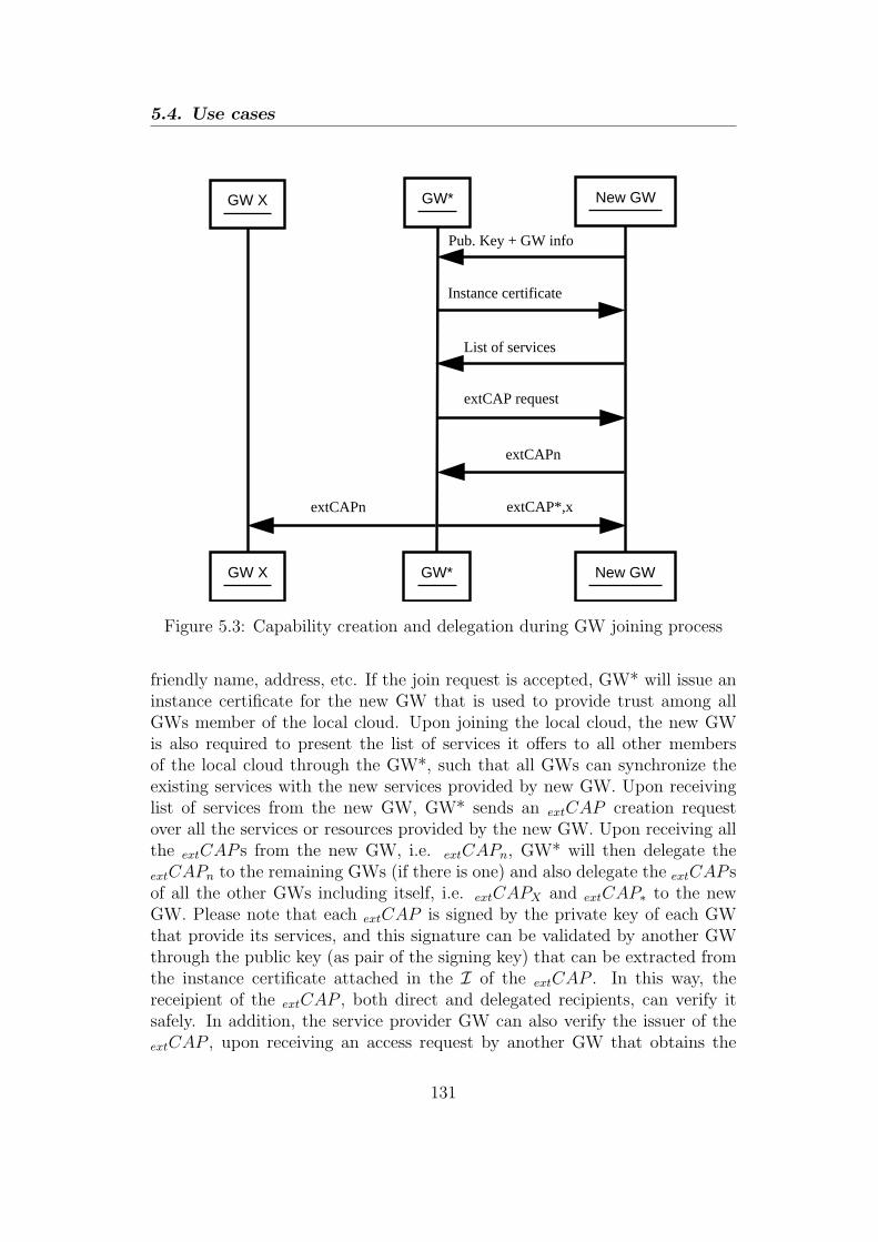
5.4. Use cases
GW* New GW
GW* New GW
Pub. Key + GW info
Instance certificate
GW X
GW X
extCAPn
extCAPn
extCAP request
List of services
extCAP*,x
Figure 5.3: Capability creation and delegation during GW joining process
friendly name, address, etc. If the join request is accepted, GW* will issue aninstance certificate for the new GW that is used to provide trust among allGWs member of the local cloud. Upon joining the local cloud, the new GWis also required to present the list of services it offers to all other membersof the local cloud through the GW*, such that all GWs can synchronize theexisting services with the new services provided by new GW. Upon receivinglist of services from the new GW, GW* sends an extCAP creation requestover all the services or resources provided by the new GW. Upon receiving allthe extCAP s from the new GW, i.e. extCAPn, GW* will then delegate the
extCAPn to the remaining GWs (if there is one) and also delegate the extCAP sof all the other GWs including itself, i.e. extCAPX and extCAP∗ to the newGW. Please note that each extCAP is signed by the private key of each GWthat provide its services, and this signature can be validated by another GWthrough the public key (as pair of the signing key) that can be extracted fromthe instance certificate attached in the I of the extCAP . In this way, thereceipient of the extCAP , both direct and delegated recipients, can verify itsafely. In addition, the service provider GW can also verify the issuer of the
extCAP , upon receiving an access request by another GW that obtains the
131
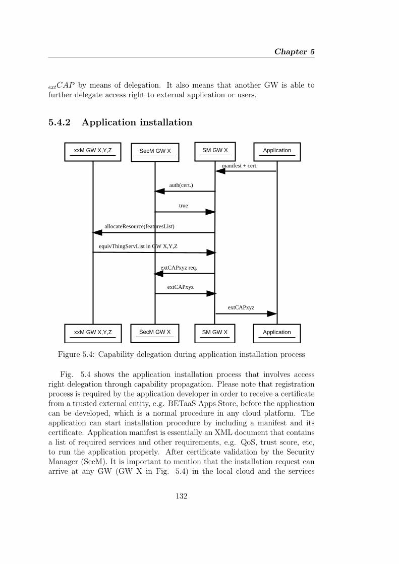
Chapter 5
extCAP by means of delegation. It also means that another GW is able tofurther delegate access right to external application or users.
5.4.2 Application installation
SM GW X Application
SM GW X Application
manifest + cert.
xxM GW X,Y,Z
xxM GW X,Y,Z
SecM GW X
SecM GW X
auth(cert.)
true
allocateResource(featuresList)
equivThingServList in GW X,Y,Z
extCAPxyz req.
extCAPxyz
extCAPxyz
Figure 5.4: Capability delegation during application installation process
Fig. 5.4 shows the application installation process that involves accessright delegation through capability propagation. Please note that registrationprocess is required by the application developer in order to receive a certificatefrom a trusted external entity, e.g. BETaaS Apps Store, before the applicationcan be developed, which is a normal procedure in any cloud platform. Theapplication can start installation procedure by including a manifest and itscertificate. Application manifest is essentially an XML document that containsa list of required services and other requirements, e.g. QoS, trust score, etc,to run the application properly. After certificate validation by the SecurityManager (SecM). It is important to mention that the installation request canarrive at any GW (GW X in Fig. 5.4) in the local cloud and the services
132

5.5. Conclusion
required by the application can be provided by all the other GWs. Therefore,Service Manager (SM) of GW X sends a polling to all participating GWsasking them whether they provide services required by the application. Noticethat the illustration in Fig. 5.4 has been really shortened to avoid irrelevantsequence diagram that involves other managers (xxM). Upon receiving a listof equivalent services by all GWs, the SM would then request the extCAPns ofall the equivalent services. Thanks to the access right delegation feature, theSecM of GWX can delegate extCAPns that correspond to all equivalent servicesprovided by all GWs, thus providing simplicity and flexibility in the applicationinstallation. As mentioned earlier in Section 5.4.1, when application accessesthe service for the first time, the GW service provider is able to validate thedelegated extCAPn by verifying the GW X’s certificate. In the same way,the application can further delegate the extCAPn to its user (assuming theapplication is hosted the external server), and the GW service provider isable to validate the delegated extCAPn by verifying application’s certificate.However, the user of that particular application is not able to delegate the
extCAPn since it is registered in the external server, thus the corresponding GWis not able to validate the extCAPn. Nevertheless, if the user is registered inthe local cloud platform itself, then the user is able to delegate its extCAPn anyexternal applications. Thus, it provides flexible yet restricted access controlby secure certificate or user credential verification.
5.5 Conclusion
Despite having a critical role, access control in the M2M local cloud platformis faced with unique challenges due to distributed nature of the platform. Acapability-based access control coupled with the key management mechanismhave been proposed in this paper, providing a secure and scalable access controlmechanism with flexible right delegation feature. Some use cases have beenpresented to show how the proposed approach can provide the desired featuresin some operations of the real platform. Although the use cases are taken fromBETaaS project, it is also applicable to any cloud platform.
Currently, the proposed access control mechanism is still under develop-ment in the context of BETaaS project. It is therefore in our interest to testhow the proposed capability-based access control approach will work in thereal platform deployment and what results can be obtained out of it.
133

Chapter 5
5.6 References
[1] Bayu Anggorojati, Parikshit N. Mahalle, Neeli R. Prasad, and RamjeePrasad. Secure access control and authority delegation based on capabilityand context awareness for federated iot. In Fabrice Theoleyre and Ai-Chun Pang, editors, Internet of Things and M2M Communications. RiverPublisher, 2013.
[2] BETaaS. D3.1.2 - betaas architecture. Technical report, Building theEnvironment for the Things as a Service (BETaaS), 2014.
[3] L. Gong. A secure identity-based capability system. In Security andPrivacy, 1989. Proceedings., 1989 IEEE Symposium on, pages 56 –63,may 1989.
[4] S. Gusmeroli, S. Piccione, and D. Rotondi. A capability-based securityapproach to manage access control in the internet of things. Mathematicaland Computer Modelling, 58(5-6):1189 – 1205, 2013.
[5] Darrel Hankerson, Alfred J. Menezes, and Scott Vanstone. Guide to El-liptic Curve Cryptography. Springer-Verlag New York, Inc., Secaucus, NJ,USA, 2003.
[6] George Labropoulos. D1.2.1 - user and system requirements. Technicalreport, BETaaS, 2012.
[7] OAuth. Oauth 2.0. http://oauth.net.
[8] Rodrigo Roman, Jianying Zhou, and Javier Lopez. On the features andchallenges of security and privacy in distributed internet of things. Com-puter Networks, 57(10):2266 – 2279, 2013.
[9] R.S. Sandhu, E.J. Coyne, H.L. Feinstein, and C.E. Youman. Role-basedaccess control models. Computer, 29(2):38 –47, feb 1996.
[10] Xively. Api docs - security.
134
6Intrusion Detection Game in AccessControl System for the M2M Local
Cloud Platform: A Game TheoreticalApproach
A distributed M2M local cloud platform which consists of distributed M2Mgateways, needs to be equipped with an Intrusion Detection System (IDS)to monitor its resources against security attacks, especially from the insider,e.g. another gateway within the local cloud. In this chapter, the interactionbetween rational attacker and defender in the context of an M2M local cloudplatform as a multi-stage Bayesian game is studied. In this game formulation, adefender is able to update its belief upon the maliciousness of the attacker. Thefeasible Nash equilibrium of the game is reviewed and an analytical frameworkfor the rational attacker and defender is provided for a given set of resourceswith different security values under some constraints on the attack and monitorresources. In the numerical analysis, it can be shown that by having multipleresources to be attacked and/or monitored simultaneously provides a kind ofdiversity which helps to improve the belief update of the defender.
135

Chapter 6
6.1 Introduction
The attacks coming from insider is a great security threat to the IT systemsand networks in general, not only in the impact but also in the quantity. Todetect and mitigate such threat is a difficult task for the access control systemwhich requires to control access permission to important resources within thesystem through a set of policies [5]. To this end, an IDS is needed as theintegral part of the access control system to detect the various threats.
A distributed local cloud concept in the M2M system deployment has beenproposed recently in BETaaS project [9]. The local cloud platform is hostedby multiple M2M gateways cooperating with each other in order to leveragethe set of M2M services provided by each gateway. The M2M gateway canbe a router, set-top box, or other computing devices (e.g. even tablet andsmart phone) that act as a gateway to the M2M devices, thus a local cloud isequivalent to a network of distributed M2M gateways.
Having distributed M2M gateways cooperating with each other forming alocal cloud, it is necessary for each gateway to define a set of access controlpolicies to restrict access to its own set of resources from other nodes within alocal cloud, including the malicious ones. Here, resources of a gateway includesensor, actuator, data, and service, with different levels of security values, i.e.depending on their cost and importance. The node refers to the M2M gateway,or gateway in short, because gateway is the main actor that enables local cloud,and malicious gateway is a gateway that would cause security threat to thenetwork by attacking the resources owned by another gateway.
We can imagine a situation where a malicious node disguises as a goodnode such that it can join the local cloud, but once it becomes part of thecloud it would cause a huge damage to the system. For example it couldmanipulate access right of an actuator controlled by a gateway, e.g. to opena gate or turning on or off some switches, stealing some sensitive data fromsensors, and so on. We should keep in mind that this local cloud environmentis heterogeneous and the human interaction should be as minimum as possible.Therefore, the IDS should be able to learn and update its knowledge based onthe interaction with the other nodes.
This chapter models and analyses the interaction between malicious node(attacker) and the regular node with IDS (defender) with game theory, in or-der to suggest the best strategies for both sides. Game theory is an analyticalframework used to model rational decision making or strategies of multipleagents having different objectives interacting with each other in the same sys-tem. Numerous works related to game theory and IDS have been carried out,
136
6.2. Related works
each with different objectives [1, 11, 4, 3]. In this chapter, the game is formu-lated as a multi-stage Bayesian game, as the defender has no prior knowledgeabout the node it is interacting with, i.e. whether it is malicious or innocent.Through the interactions, which is modelled in a multi-stage game, the de-fender is able to update its belief about the attacker intention via Bayes rule.On a side note, further action can be taken by the defender, e.g. removing themalicious gateway from the local cloud, once its belief about the attacker be-ing malicious converges to one. Finally, an optimum strategy for both attackerand defender will be derived by considering their respective costs and benefits.
The remaining of this chapter is organized as follows: A review of somerelated works within the field of game theory in security and intrussion de-tection is described in section 6.2. A brief overview of a M2M local cloudsystem along with its security consideration is presented in section 6.3. Thegame model and definition of sensible resource set are described in section 6.4.The analysis of proposed multi-stage Bayesian game is explained section 6.5.A numerical analysis is performed in section 6.6. Finally, the conclusion andfuture outlooks are given in section 6.7.
6.2 Related works
Game theory has been applied widely in modelling the network security system,including the interaction between IDSs and the attackers. Alpcan and Basar[1] model the intrusion detection in access control system as a non-cooperativenon-zero-sum game in both finite and continuous-kernel versions. The IDSsensor network is also introduced in their model as a fictitious player whichmodels the imperfect detection capabilities of the sensor. The existence anduniqueness of the Nash Equilibrium (NE) was shown, and the repeated gamesof the continuous-kernel version was studied analytically and numerically bythe authors. Bloem et al. further developed an algorithm to optimally allocatebetween system administrator’s response under the time and effort constraintsin managing the attacks, and the automatic response to the attacks with someimperfections [2], as a discrete model based on the continuous game versionin [1]. The overall cost function is minimized as the linear programming op-timization problem, and the simulation results of the algorithm are presentedby the authors.
Y. Liu et al. [11] model the attacker and IDS in the ad hoc wireless networksas a Bayesian game, in both static and dynamic or repeated game. The PerfectBayesian Equilibrium (PBE) of the game is shown, and a hybrid IDS at the
137

Chapter 6
defender side is proposed in order to balance the trade off between the energycost and monitoring gain. Chen et al. [4] proposed a framework which appliestwo stages of game theoretical models for economical deployment of intrusiondetection agent. In their model, the first scheme models a two-person non-cooperative game between the attacker and IDS agent, and a unique securityrisk value, which is the NE derived from the proposed pay-off functions, isassigned to the agent. The second scheme uses the security risk value tocompute the Shapley value of intrusion detection agent in order to grouped theIDS agents into coalition groups by the various threat levels so as to providefair and optimal IDS deployment.
Chen and Leneutre [3] model the game theoretical framework for IDS inheterogeneous networks consisting of nodes with different non-correlated secu-rity assets. In the model, a non-cooperative game is considered and a set ofsensible targets with various attack and monitor resource constraints is defined,in order to analyse and derive the NEs. Various feasible NEs for different typesof game, i.e. two-person game, multiple attackers/defenders, Stackelberg Net-work Intrusion Detection Game, and the game with generalized attack model,are studied, and a numerical study is performed to validate the analyticalresults.
A dynamic Bayesian game between regular and malicious nodes in mobilead-hoc networks is studied in [10]. In the model, the regular node would eithercooperate or decline the cooperation with another node, and the maliciousnode would either attack or cooperate with another node in order to confuseor deceive the opponent. On top that, the regular node has an option toreport the malicious node at certain point, i.e. after it receives enough evidenceprovided that the reporting gives better pay-off than the other actions. On theother hand, the malicious node has an option to flee provided that the pay-offof fleeing is higher than the risk of being reported. The pure, mixed, and PBEstrategies of both types of players are studied, and the simulation results toevaluate those strategies are presented.
6.3 The M2M local cloud system and security
consideration
The M2M local cloud system considered in this chapter refers to the platformbeing introduced and developed in BETaaS project. According to BETaaSdescription in [9], it is a content-centric platform distributed over a local cloud,
138
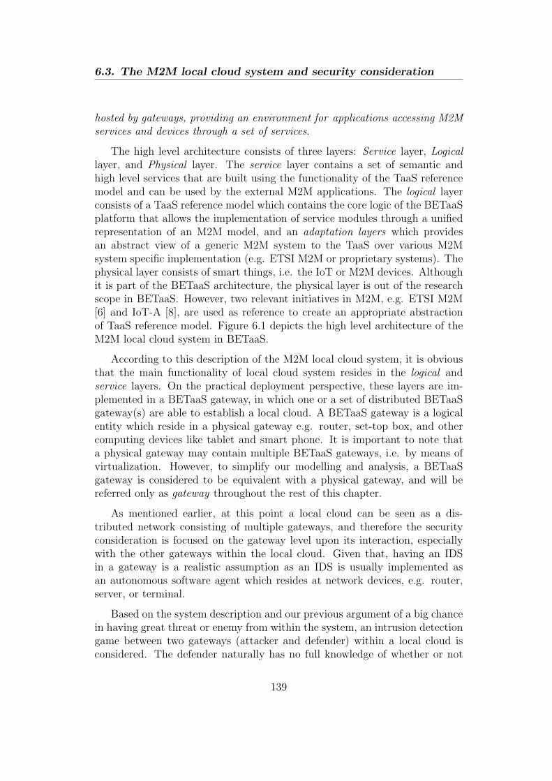
6.3. The M2M local cloud system and security consideration
hosted by gateways, providing an environment for applications accessing M2Mservices and devices through a set of services.
The high level architecture consists of three layers: Service layer, Logicallayer, and Physical layer. The service layer contains a set of semantic andhigh level services that are built using the functionality of the TaaS referencemodel and can be used by the external M2M applications. The logical layerconsists of a TaaS reference model which contains the core logic of the BETaaSplatform that allows the implementation of service modules through a unifiedrepresentation of an M2M model, and an adaptation layers which providesan abstract view of a generic M2M system to the TaaS over various M2Msystem specific implementation (e.g. ETSI M2M or proprietary systems). Thephysical layer consists of smart things, i.e. the IoT or M2M devices. Althoughit is part of the BETaaS architecture, the physical layer is out of the researchscope in BETaaS. However, two relevant initiatives in M2M, e.g. ETSI M2M[6] and IoT-A [8], are used as reference to create an appropriate abstractionof TaaS reference model. Figure 6.1 depicts the high level architecture of theM2M local cloud system in BETaaS.
According to this description of the M2M local cloud system, it is obviousthat the main functionality of local cloud system resides in the logical andservice layers. On the practical deployment perspective, these layers are im-plemented in a BETaaS gateway, in which one or a set of distributed BETaaSgateway(s) are able to establish a local cloud. A BETaaS gateway is a logicalentity which reside in a physical gateway e.g. router, set-top box, and othercomputing devices like tablet and smart phone. It is important to note thata physical gateway may contain multiple BETaaS gateways, i.e. by means ofvirtualization. However, to simplify our modelling and analysis, a BETaaSgateway is considered to be equivalent with a physical gateway, and will bereferred only as gateway throughout the rest of this chapter.
As mentioned earlier, at this point a local cloud can be seen as a dis-tributed network consisting of multiple gateways, and therefore the securityconsideration is focused on the gateway level upon its interaction, especiallywith the other gateways within the local cloud. Given that, having an IDSin a gateway is a realistic assumption as an IDS is usually implemented asan autonomous software agent which resides at network devices, e.g. router,server, or terminal.
Based on the system description and our previous argument of a big chancein having great threat or enemy from within the system, an intrusion detectiongame between two gateways (attacker and defender) within a local cloud isconsidered. The defender naturally has no full knowledge of whether or not
139
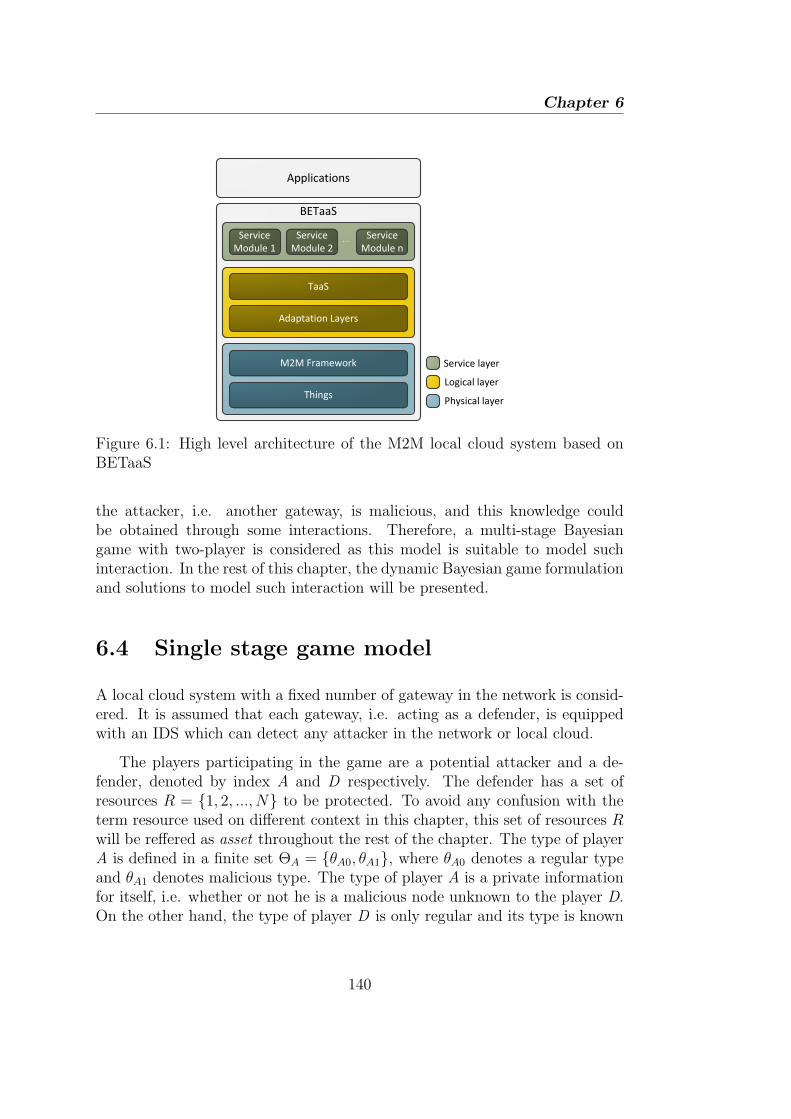
Chapter 6
BETaaS
Service
Module 1
Service
Module 2
Service
Module n
TaaS
Adaptation Layers
M2M Framework
Things
Applications
Service layer
Logical layer
Physical layer
Figure 6.1: High level architecture of the M2M local cloud system based onBETaaS
the attacker, i.e. another gateway, is malicious, and this knowledge couldbe obtained through some interactions. Therefore, a multi-stage Bayesiangame with two-player is considered as this model is suitable to model suchinteraction. In the rest of this chapter, the dynamic Bayesian game formulationand solutions to model such interaction will be presented.
6.4 Single stage game model
A local cloud system with a fixed number of gateway in the network is consid-ered. It is assumed that each gateway, i.e. acting as a defender, is equippedwith an IDS which can detect any attacker in the network or local cloud.
The players participating in the game are a potential attacker and a de-fender, denoted by index A and D respectively. The defender has a set ofresources R = {1, 2, ..., N} to be protected. To avoid any confusion with theterm resource used on different context in this chapter, this set of resources Rwill be reffered as asset throughout the rest of the chapter. The type of playerA is defined in a finite set ΘA = {θA0, θA1}, where θA0 denotes a regular typeand θA1 denotes malicious type. The type of player A is a private informationfor itself, i.e. whether or not he is a malicious node unknown to the player D.On the other hand, the type of player D is only regular and its type is known
140

6.4. Single stage game model
by both players A and D. Given that, player D ’s belief about the type of playerA being malicious is expressed as a prior probability, denoted by µ0.
The interaction between attacker and defender is modelled as a non-cooperativegame, which extends the basic two-player game formulation in [3] into a Bayesiangame. The malicious type of playerA has two pure strategiesAAm = {aA0, aA1},where aA0 denotes strategy Not attack and aA1 denotes strategy Attack, andthe regular type of player A has only one pure strategy: AAr = {aA0}. Here,the objective of the malicious type of player A is to attack a set of assetsR without being detected. On the other hand, the player D has two purestrategies: AD = {aD0, aD1}, where aD0 denotes strategy Not monitor andaD1 denotes strategy Monitor. Here, the action Monitor refers to monitoringa set of its own assets R so as to minimize its loss or optimize its payoff.
It is assumed that each asset i ∈ R worth of a security asset valueWi, whereWi > 0. In reality, Wi could be an economic value of the asset, whose valuemay depend on how valuable the information it holds, its role in the network,etc. Therefore −Wi expresses the loss of security value due to a successfulattack, e.g. loss of important data or data integrity, loss of revenue due todamage of a certain asset, etc. It is also assumed that upon a successful attackof asset i, both player A and D receive an equal gain/loss Wi, i.e. the payoff forplayer A and D is Wi and −Wi respectively. In this chapter, it is assumed thatthe security assets of different assets are independent. This assumption holdsfor ad-hoc network scenario where each node operates independently of eachother [3], e.g. in our case ad-hoc nodes represent the the sensors or actuatorsoperating ”behind” the gateway.
In general, the player A’s strategy is to attack a set of assets R undera probability distribution p = {p1, p2, ..., pN}, where pi is the probability ofattacking asset i and
∑i∈R pi ≤ P ≤ 1 indicates the resource constraint of the
player A. On the defender D side, its strategy is to monitor a set of assets R inorder to detect the attacks with a probability distribution q = {q1, q2, ..., qN},where qi is the probability of monitoring the asset i and
∑i∈R qi ≤ Q ≤ 1
indicates the player D ’s resource constraint.
Table 6.1 illustrates the payoff matrix of the attacker/defender Bayesiangame for the asset i in strategic form. In the matrix, the x and y denote thedetection rate (true positive) and false alarm rate, i.e. false positive rate, ofthe IDS respectively, and x, y ∈ [0, 1]. The cost of attacking and monitoringof asset i ∈ R are denoted by CaWi and CmWi respectively, and are assumedto be proportional to the security asset value of i, Wi. CfWi denotes the costof a false alarm. In this study, the Ca, Cm ∈ [0, 1) is assumed so as to giveincentive to player A/D to attack/monitor.
141

Chapter 6
Table 6.1: Strategic form of the attacker/defender Bayesian game for the asseti
Monitor Not monitorAttack (1− 2x)Wi − CaWi, Wi − CaWi, −Wi
(2x− 1)Wi − CmWi
Not attack 0, −yCfWi − CmWi 0, 0
(a) Player A is malicious with prior probability µ0
Monitor Not monitorNot attack 0, −yCfWi − CmWi 0, 0
(b) Player A is regular with prior probability 1− µ0
In Table 6.1a, for the strategy combination (Attack, Not monitor), player Dpayoff is −Wi, and the malicious type of player A’s payoff is his gain of successminus the attacking cost, i.e. Wi − CaWi. For the strategy combination (At-tack, Monitor), the overall payoffs of both players are defined as the expectedgain/loss of detecting the attack minus the cost of monitoring/attacking asseti, i.e. CmWi and/or CaWi respecively. The expected gain of detecting theattack depends on the value of x, which is xWi − (1 − x)Wi = (2x − 1)Wi,where 1− x is the false negative rate. On the other hand, the player A wouldreceive an equivalent gain due to the defender’s loss, i.e. (1− 2x)Wi. For theother two strategy combinations, when player A plays Not attack, his payoff isalways 0. On the other hand, player D ’s payoff is 0 if she does not monitor,and a monitoring cost of CmWi plus an expected loss of yCfWi due to falsealarms would be utilized if the monitor strategy is chosen. Please note that forthe payoff matrix in Table 6.1b, i.e. if player A is a regular type, it basicallyhas a similar payoffs combination to the second row of the payoff matrix inTable 6.1a.
The overall payoffs of both player A and D are defined as the followingutility functions:
UA(p,q) =∑i∈R
[piqiWi(1− 2x− Ca) + (1− qi)Wi(1− Ca)]
=∑i∈R
piWi(1− 2xqi − Ca)(6.1)
142

6.5. Proposed multi-stage Bayesian game
UD(p,q) =∑i∈R
[µ0(piqiWi(2x− 1− Cm) + (1− pi)qiWi(−yCf − Cm)
+ pi(1− qi)(−Wi)) + (1− µ0)qiWi(−yCf − Cm)]
=∑i∈R
qiWi(p(2x+ yCf )µ0 − (yCf + Cm))−∑i∈R
µ0piWi
(6.2)
6.4.1 Sensible set of assets
In order to optimize its strategy under some attack resource constraint, arational attacker A would rather to focus its attacks to some assets to minimizethe risk of being detected, which has been shown by Chen and Leneutre in [3].Given a set of resource R, it is assumed that each asset has a security assetvalue Wi sorted in the following order: W1 ≥ W2 ≥ · · · ≥ WN , and the sensibleassets set RS and the quasi-sensible asset set RQ are defined such that
Wi >|Rs|.(1−Ca)−2xQ
(1−Ca)
(∑j∈Rs
1Wj
) , ∀i ∈ RS
Wi =|Rs|.(1−Ca)−2xQ
(1−Ca)
(∑j∈Rs
1Wj
) , ∀i ∈ RQ
Wi <|Rs|.(1−Ca)−2xQ
(1−Ca)
(∑j∈Rs
1Wj
) , ∀i ∈ R−RS −RQ
(6.3)
where |RS| is the cardinality of RS, and R − RS − RQ denotes the set ofassets in set of assets R but neither in RS nor RQ. According to [3], RS
consists of NA assets with the largest security asset values such that theyincentive for player A to attack them. On the other hand, attacking any asseti ∈ R−RS−RQ gives no incentives to attacker A. In other words, focusing onlyto attack the assets set RS and RQ is enough to maximize the attacker’s payoff,while the security assets values of set of assets R−RS−RQ are not ”attractive”enough to draw attacker’s A attention, even if they are not monitored by thedefender D. Consequently, the defender D has no incentive to monitor anyasset i ∈ R−RS −RQ.
6.5 Proposed multi-stage Bayesian game
To analyse the multi-stage Bayesian intrusion detection game, it is assumedthat the single stage Bayesian game model is played repeatedly in each timeperiod tk, k = 0, 1, .... The payoffs of each player in each stage of the game
143

Chapter 6
are the same as the payoffs defined in Section 6.4. To simplify the analysis,the discount factor with respect to each player’s payoff is not considered, thusthe payoffs remain the same in each stage. Another assumption is that eachof the gateway has been authenticated upon joining the local cloud, thus theidentity of all the gateway, i.e. player, is maintained throughout the game.
At the beginning of each stage game, e.g. time period tk, each playerchooses its action among its own pure strategy set simultaneously that is re-vealed at the end of the stage. In this case, a malicious type of player A willchoose its action at time tk, aA(tk), from its strategies set AAm = {aA0, aA1},and similarly player D chooses action aD(tk) from the strategies set AD ={aD0, aD1}. In addition, the single stage game model in section 6.4 implicitlysuggests that the game is played by each player using mixed strategy, i.e. aprobability distribution over pure strategies [7]. Similarly in the multi-stageBayesian game, a strategy of each player prescribes a behaviour strategy whichessentially is a probability distribution σ that maps the set of possible set ofaction history profile h(tk) = (a(t0), a(t1), ..., a(tk−1)) and types θ into the ac-tion spaces a, i.e. σ(a|θ, h(tk)) [7]. In our case, the behaviour strategy of playerA is defined as σA(a
iA(tk)|θA, hi
A(tk)), where θA denotes any type of player Awithin a set ΘA, h
iA(tk) = (aiA(t0), a
iA(t1), ..., a
iA(tk−1)) indicates the history
profile of player A with respect to asset i ∈ R that belongs to player D at thebeginning of stage tk, and aiA(tk) represents the action profile of player A withrespect to asset i ∈ R at stage tk. Likewise, the behaviour strategy of playerD is defined as σD(a
iD(tk)|θD, hA
i (tk)).
Following the mixed strategies of both players defined in section 6.4, i.e.the attack probability p and monitor probability q over the asset i ∈ R, theset of behaviour strategy σ of each player in each stage game tk can be definedas follows:
σA(aiA1(tk)|θA, hi
A(tk)) = pi
σA(aiA0(tk)|θA, hi
A(tk)) = P − pi
σD(aiD1(tk)|θD, hi
D(tk)) = qi
σD(aiD0(tk)|θD, hi
D(tk)) = Q− qi
Player D who has no knowledge of player A’s type θA, has to chooseits strategy at each stage game tk according to its belief about the type ofplayer A at the beginning of the stage. By observing the action and historyprofile of player A towards the asset i ∈ R at the end of the stage game,player D is able to update its belief on the posterior probability distribution
144
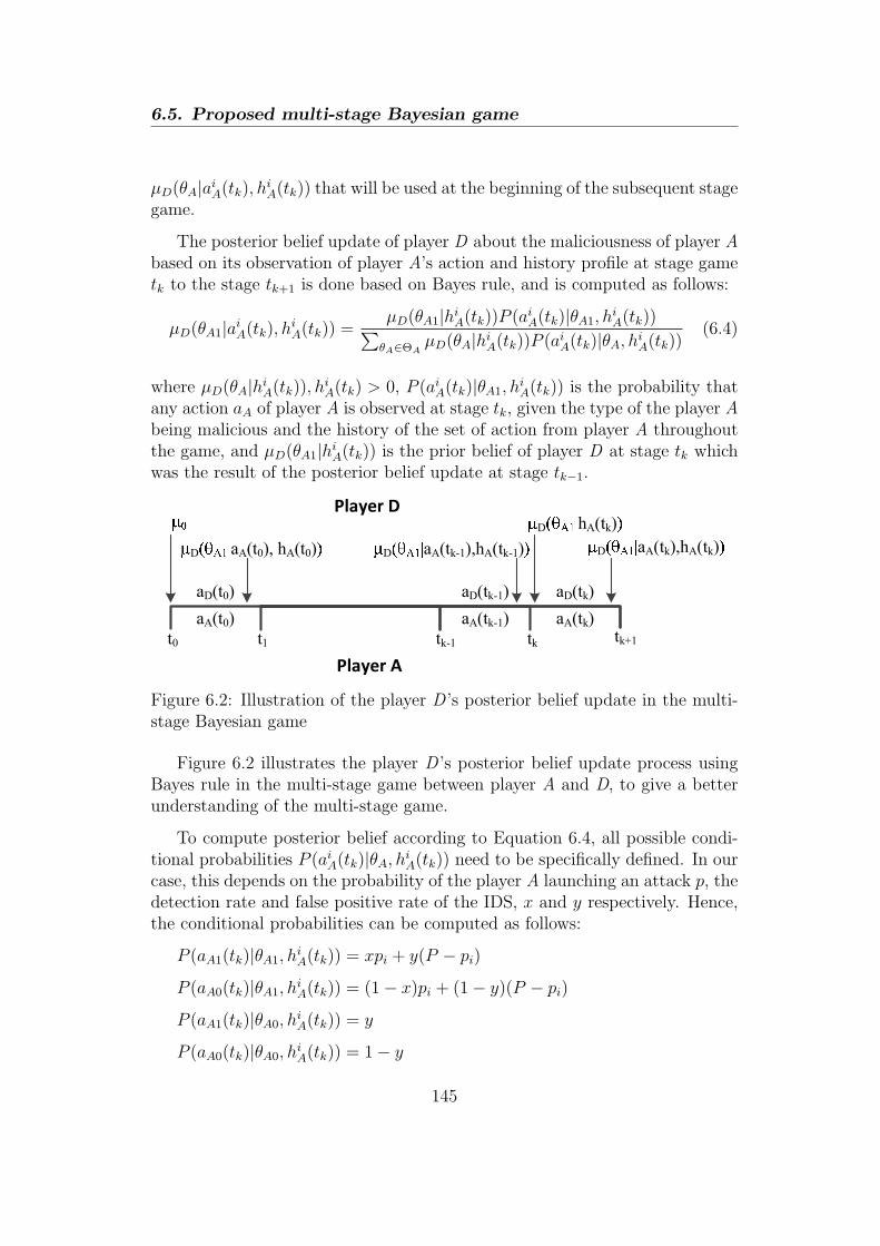
6.5. Proposed multi-stage Bayesian game
µD(θA|aiA(tk), hiA(tk)) that will be used at the beginning of the subsequent stage
game.
The posterior belief update of player D about the maliciousness of player Abased on its observation of player A’s action and history profile at stage gametk to the stage tk+1 is done based on Bayes rule, and is computed as follows:
µD(θA1|aiA(tk), hiA(tk)) =
µD(θA1|hiA(tk))P (aiA(tk)|θA1, h
iA(tk))∑
θA∈ΘAµD(θA|hi
A(tk))P (aiA(tk)|θA, hiA(tk))
(6.4)
where µD(θA|hiA(tk)), h
iA(tk) > 0, P (aiA(tk)|θA1, h
iA(tk)) is the probability that
any action aA of player A is observed at stage tk, given the type of the player Abeing malicious and the history of the set of action from player A throughoutthe game, and µD(θA1|hi
A(tk)) is the prior belief of player D at stage tk whichwas the result of the posterior belief update at stage tk−1.
Player A
Player D
t0 t1 tk-1
aA(t0)
aD(t0)
D aA(t0), hA(t0) D aA(tk-1),hA(tk-1)
D hA(tk)
tk
aA(tk-1)
aD(tk-1)
aA(tk)
aD(tk)
D aA(tk),hA(tk)
tk+1
Figure 6.2: Illustration of the player D ’s posterior belief update in the multi-stage Bayesian game
Figure 6.2 illustrates the player D ’s posterior belief update process usingBayes rule in the multi-stage game between player A and D, to give a betterunderstanding of the multi-stage game.
To compute posterior belief according to Equation 6.4, all possible condi-tional probabilities P (aiA(tk)|θA, hi
A(tk)) need to be specifically defined. In ourcase, this depends on the probability of the player A launching an attack p, thedetection rate and false positive rate of the IDS, x and y respectively. Hence,the conditional probabilities can be computed as follows:
P (aA1(tk)|θA1, hiA(tk)) = xpi + y(P − pi)
P (aA0(tk)|θA1, hiA(tk)) = (1− x)pi + (1− y)(P − pi)
P (aA1(tk)|θA0, hiA(tk)) = y
P (aA0(tk)|θA0, hiA(tk)) = 1− y
145

Chapter 6
where 1−x indicates the false negative (miss detection) rate, and 1−y indicatesthe true negative rate.
6.5.1 PBE analysis
In a multi-stage game, the best strategy of each player should represent a NashEquilibrium in every stage game of the whole game which known as subgameperfect equilibrium. Those strategies are determined by considering the re-sponses or reactions of the other players in each stage of the game. However,the opponent’s in a dynamic game with incomplete information responses arehighly dependent on the player’s belief about the opponent. To extend thesubgame perfection in a dynamic Bayesian game, i.e. PBE, it is necessaryto obtain strategies that yield a Bayesian Nash equilibrium not only for thewhole game, but also at every stage of the game. In order to satisfy this, theplayers’ belief about the opponent must be specified at the beginning of eachstage game. As mentioned earlier, the player’s belief is updated according tothe Bayes rule.
In what follows, the existence of PBE in the proposed multi-stage IDS gameis shown and then the mixed strategies equilibrium are determined. First, itis shown that the proposed multi-stage game satisfies the Bayesian conditionsB(i)-B(iv) and equilibrium condition P, which guarantee that the incomplete-information game has a PBE [7].
Lemma 1. The described multi-stage IDS game satisfies the four Bayesianconditions [7]:
B(i) Posterior beliefs are independent, and all types of player D have thesame beliefs, for all θ, t, and h(tk). It requires that even unexpected events willnot change the independence assumption for the type of the opponents.
B(ii) Bayes’ rule is used to update beliefs from µD(θA|hiA(tk)) to µD(θA|hi
A(tk+1))whenever possible.
B(iii) The players do not signal what they do not know.
B(iv) All players must have the same belief about the type of another player.
Proof. B(i) is satisfied because player D has only one type. From the pro-posed belief updating system, the game satisfies B(ii). Condition B(iii) meansµD(θA1|aiA(tk), hi
A(tk)); µD(θA1|aiA(tk), hiA(tk)), if a
iA(tk) = aiA(tk). In our IDS
game, the belief update of player D about player A’s type is only influencedby player A’s signal, thus B(iii) is satisfied. Since there are only two players
146
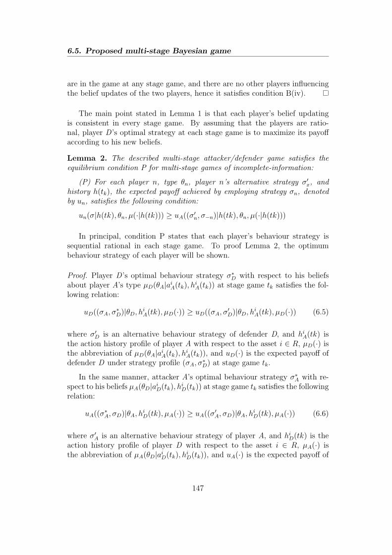
6.5. Proposed multi-stage Bayesian game
are in the game at any stage game, and there are no other players influencingthe belief updates of the two players, hence it satisfies condition B(iv).
The main point stated in Lemma 1 is that each player’s belief updatingis consistent in every stage game. By assuming that the players are ratio-nal, player D ’s optimal strategy at each stage game is to maximize its payoffaccording to his new beliefs.
Lemma 2. The described multi-stage attacker/defender game satisfies theequilibrium condition P for multi-stage games of incomplete-information:
(P) For each player n, type θn, player n’s alternative strategy σ′x, and
history h(tk), the expected payoff achieved by employing strategy σn, denotedby un, satisfies the following condition:
un(σ|h(tk), θn, µ(·|h(tk))) ≥ uA((σ′n, σ−n)|h(tk), θn, µ(·|h(tk)))
In principal, condition P states that each player’s behaviour strategy issequential rational in each stage game. To proof Lemma 2, the optimumbehaviour strategy of each player will be shown.
Proof. Player D ’s optimal behaviour strategy σ∗D with respect to his beliefs
about player A’s type µD(θA|aiA(tk), hiA(tk)) at stage game tk satisfies the fol-
lowing relation:
uD((σA, σ∗D)|θD, hi
A(tk), µD(·)) ≥ uD((σA, σ′D)|θD, hi
A(tk), µD(·)) (6.5)
where σ′D is an alternative behaviour strategy of defender D, and hi
A(tk) isthe action history profile of player A with respect to the asset i ∈ R, µD(·) isthe abbreviation of µD(θA|aiA(tk), hi
A(tk)), and uD(·) is the expected payoff ofdefender D under strategy profile (σA, σ
∗D) at stage game tk.
In the same manner, attacker A’s optimal behaviour strategy σ∗A with re-
spect to his beliefs µA(θD|aiD(tk), hiD(tk)) at stage game tk satisfies the following
relation:
uA((σ∗A, σD)|θA, hi
D(tk), µA(·)) ≥ uA((σ′A, σD)|θA, hi
D(tk), µA(·)) (6.6)
where σ′A is an alternative behaviour strategy of player A, and hi
D(tk) is theaction history profile of player D with respect to the asset i ∈ R, µA(·) isthe abbreviation of µA(θD|aiD(tk), hi
D(tk)), and uA(·) is the expected payoff of
147
Chapter 6
player A under strategy profile (σ∗A, σD) at stage game tk. Since player D has
only one type, Equation 6.6 reduces to
uA((σ∗A, σD)|θA, hi
D(tk)) ≥ uA((σ′A, σD)|θA, hi
D(tk)) (6.7)
Based on the optimum strategies of each player defined in Equation 6.5 and6.7, given player D ’s belief µD, the multi-stage attacker/defender game has astrategy pair σ = (σ∗
A, σ∗D) that satisfies the above inequality formula, hence
the equilibrium condition P is satisfied.
Theorem 1. The described multi-stage IDS game has a perfect Bayesian equi-librium.
Proof. Since the described multi-stage attacker/defender game satisfies thefour Bayesian conditions B(i)-B(iv) (Lemma 1) and the equilibrium conditionP (Lemma 2), the game has a strategy profile (σ, µ), where σ = (σ∗
A, σ∗D) is
a strategy pair for the two players, and µ = (µA(θD|hiD(tk)), µD(θA|hi
A(tk)))is the vector of beliefs for the two players. Note that µA is not needed sinceplayer D ’s type is common knowledge. By the definition of PBE [7], (σ, µ) isa PBE.
Next, the types of potential PBE, namely separating equilibrium, poolingequilibrium, and hybrid equilibrium [7], are analysed. In our IDS game, theseparating equilibrium cannot be satisfied because the Attack launched by themalicious type of player A cannot perfectly reveals its type to player D due tothe error detection rate that the IDS has. On the other hand, player A onlywants to play Not attack if by playing the opposite it will receive a negativereward. Therefore, it can be seen that the only type of PBE exists in ourgame is of hybrid or semi-separating equilibrium, in which both players mayrandomize or mix their strategies in order to maximize their respective payoff,while none of them have incentive to deviate from the equilibrium strategies.This also confirms the existence of mixed strategy equilibrium solution in eachstage game.
Please recall that there is a set of assets i ∈ R with different securityvalues to be attacked and monitored by player A and D respectively, under agiven resource constraint to each player. In such a case, the mixed strategyequilibrium should be determined by analyzing different cases, i.e. dependingon the resource constrains. For this purpose, a similar analysis explained in[3] will be followed.
148

6.5. Proposed multi-stage Bayesian game
First, let (p∗,q∗, µ(·)) denote the PBE of the game, and given the utilityfunctions of each player, UA and UD, the following relations are satisfied:
0 ≤(1− 2xq∗i − Ca)Wi = (1− 2xq∗j − Ca)Wj
≥(1− 2xq∗l − Ca)Wl∀i, j, l ∈ R, p∗i , p∗j > 0, p∗l = 0
(6.8)
0 ≤[p∗i (2x+ yCf )µD(θA1|·)− (yCf + Cm)]Wi
=[p∗j(2x+ yCf )µD(θA1|·)− (yCf + Cm)]Wj
≥[p∗l (2x+ yCf )µD(θA1|·)− (yCf + Cm)]Wl
∀i, j, l ∈ R, q∗i , q∗j > 0, q∗l = 0
(6.9)
The relationship shown in Equation 6.8 can be explained as follows: if(1 − 2xq∗i − Ca)Wi < 0, player A would better choose p∗i = 0; if (1 − 2xq∗i −Ca)Wi < (1 − 2xq∗j − Ca)Wj, then player A has incentive to decrease p∗i andincrease p∗j ; if (1− 2xq∗i − Ca)Wi < (1− 2xq∗l − Ca)Wl, then player A will getmore payoff by adding p∗i to p∗l and setting p∗i = 0. Similarly, Equation 6.9 canalso be explained in the same way.
Based on resource constraint of each player, the following cases are consid-ered:
1.∑
i∈R q∗i = Q and∑
i∈R p∗i = P
2.∑
i∈R q∗i < Q and∑
i∈R p∗i = P
3.∑
i∈R q∗i < Q and∑
i∈R p∗i < P
In Case 1, both players use up all their resources to attack or monitor. Ithappens when the security assets Wi from the set of resources are considerablyhigh as compared to the attacking or monitoring cost, therefore both playersare trying to attack and monitor the assets that have the biggest securityvalues (as pointed out in Section 6.4.1) using all of their attacking/monitoringassets. In Case 2, player A uses all its attacking resource to the limit, whileit does not give incentive for player D to utilize all its monitoring resources,due to high monitoring cost as compared to the gain it would achieve, i.e. thesecurity values of protected assets. In Case 3, both players do not use all oftheir attacking/monitoring resources because by doing so it does not give somuch incentive for both of them. This is due to high attacking and monitoringcost as compared to the security values of the assets.
From the formulation of our multi-stage Bayesian game and the Theorem2 in [3], it can be shown that the equilibrium strategies of each player in each
149

Chapter 6
of the case mentioned earlier at stage game tk, i.e. p∗i (tk) and q∗i (tk), result in
the following strategies:
1) If ND ≥ NA and NA(1− Ca) > 2xQ, then
p∗i (tk)
= PA
Wi∑NA
j=11
Wj
+yCf+Cm
(2x+yCf )µD(θA1|·)
(1− NA
Wi∑NA
j=11
Wj
), i ∈ RS
∈[0, PA
Wi∑NA
j=1
+yCf+Cm
(2x+yCf )µD(θA1|·)
(1− NA
Wi∑NA
j=11
Wj
)], i ∈ RQ
= 0 , i ∈ R−RS −RQ
q∗i (tk) =
12x
(1− Ca − NA(1−Ca)−2xQ
Wi∑NA
j=11
Wj
), i ∈ RS
0 , i ∈ R−RS
2) If ND ≤ NA
p∗i (tk)
=
yCf+Cm
(2x+yCf )µD(θA1|·),Wi > WND+1
∈[0,
yCf+Cm
(2x+yCf )µD(θA1|·)
],Wi = WND+1
= 0 ,Wi < WND+1
q∗i (tk) =
{1−Ca
2x
(1− WND+1
Wi
),Wi > WND+1
0 ,Wi ≤ WND+1
3) If ND ≥ NA and NA(1− Ca) ≥ 2xQ, then
p∗i (tk) =yCf + Cm
(2x+ yCf )µD(θA1|·), q∗i (tk) =
1− Ca
2x, i ∈ R
in this case ND = NA = N .
where ND is the number of security assets that are worth to be monitored byplayer D and is defined as ND = ⌊(2x+ yCf )P/(yCf + Cm)⌋.
6.6 Numerical analysis
In this section, some numerical analysis are performed to illustrate our analyt-ical model and the equilibrium in the described multi-stage Bayesian game.
A scenario where the attacking and monitoring costs are relatively high, i.e.due to energy or other constraints, while security values of the assetsWi, i ∈ R,
150

6.6. Numerical analysis
are not as much high a compared to the attacking and monitoring costs, isconsidered. In this case, the following cost parameters are set: Ca = Cm = 0.1,and Cf = 0.3. The detection rate and false positive rate of the IDS arex = 83.33% and y = 0.029% respectively. Ten protected assets with normalizedsecurity values are considered: Wi = 0.1 ∗ (11− i), i ∈ [1, 10]. Both attackingand monitoring resources, P and Q, are set to 1.
Table 6.2 shows the mixed strategies equilibrium in each stage game (p∗,q∗).Given its attack resource constraint, it can be seen that player A focuses onlyto attack six most valuable assets out of ten with some probabilities. Conse-quently, player D has incentive to monitor the same six assets as well.
For the purpose of illustrating how the posterior belief of player D uponobserving the player A’s action, i.e. µD(θA1|·), and how player A’s strategiesdistribution adapts the µD(θA1|·) in the multi-stage Bayesian game, a hundredstages game is run in which each player choose its own strategy simultaneouslybased on the observation in the previous stage. At the beginning of the stage,both µD(θA1|·) and µD(θA0|·) equal to 0.5. Player A decides to Attack or Notattack randomly according to the calculated equilibrium strategy p∗, and thesame way applies to player D.
Figure 6.3 and 6.4 illustrate how the posterior belief of player D evolvesupon its observation to player A’s action on the asset i = 1 and i = 5 re-spectively, over the game duration. In both figures, observed action 0 meansthat player D observes No attack, and 1 means Attack action was observed. Itis clear that the posterior belief quickly converges to 1 after observing Attackdue to high detection rate and low false alarm rate. Furthermore, it is verydifficult to reduce the posterior belief to a lower level in the next stage even a
Table 6.2: Mixed equilibrium strategies
i p∗i q∗i1 0.1183− 0.0176/µD(θA1|·) 0.27512 0.1314− 0.0128/µD(θA1|·) 0.24573 0.1478− 0.0068/µD(θA1|·) 0.20894 0.1689 + 0.0008/µD(θA1|·) 0.16165 0.1971 + 0.0110/µD(θA1|·) 0.09856 0.2365 + 0.0253/µD(θA1|·) 0.01027 0 08 0 09 0 010 0 0
151

Chapter 6
0 10 20 30 40 50 60 70 80 90 1000
0.1
0.2
0.3
0.4
0.5
0.6
0.7
0.8
0.9
1
Number of stage games tk
µ D1(θ
A1|⋅)
Posterior belief update of player D upon observed action on asset 1
µD1 (θ
A1|⋅)
observed actions
Figure 6.3: Player D ’s posterior belief update µD(θA1|·) upon its observationto player A’s action on the asset i = 1
0 10 20 30 40 50 60 70 80 90 1000
0.1
0.2
0.3
0.4
0.5
0.6
0.7
0.8
0.9
1
Number of stage games tk
µ D5(θ
A1|⋅)
Posterior belief update of player D upon observed action on asset 5
µD5 (θ
A1|⋅)
observed actions
Figure 6.4: Player D ’s posterior belief update µD(θA1|·) upon its observationto player A’s action on the asset i = 5
No attack action is observed once it is converged to 1. It can also be noticedthat having multiple assets to be monitored simultaneously quickly improvesthe posterior belief update, as chances of observing attacks toward any of theavailable asset is more than just monitoring a single asset.
Figure 6.5 illustrates how the mixed equilibrium strategy of player A, p∗,over the most valuable assets evolves in the multi-stage Bayesian game. It is
152

6.6. Numerical analysis
0 10 20 30 40 50 60 70 80 90 1000.13
0.14
0.15
0.16
0.17
0.18
0.19
0.2
0.21
0.22
Number of stage games tk
p* i(tk)
p*1(t
k) p*
2(t
k) p*
3(t
k) p*
4(t
k) p*
5(t
k) p*
6(t
k)
Figure 6.5: Player A’s best strategy p∗ in each stage game over the mostvaluable assets
0 10 20 30 40 50 60 70 80 90 100−0.8
−0.6
−0.4
−0.2
0
0.2
0.4
0.6
Number of stage games tk
U
A(t
k) U
D(t
k)
Figure 6.6: Players A’s and D ’s overall payoffs in each stage game
can be seen that at the initial stage of the game until an Attack is observedby player D, player A tries to increase or decrease its probability of attackingover different security assets in order to maintain its optimum payoff. However,when an Attack is observed, player A pulls back its attack probability to reduceits probability of being caught by player D, thus maintaining its optimumoverall payoff. It is obvious as well that p∗ converges to a steady state valueonce the µD(θA1|·) converges to 1.
153

Chapter 6
0.65 0.7 0.75 0.8 0.85 0.9 0.95 10
0.02
0.04
0.06
0.08
0.1
0.12
x’/x
|UA’−
UA| a
nd |U
D’−
UD
|
|UA’ −U
A|
|UD’ −U
D|
Figure 6.7: Players A’s and D ’s average utilities deviations, i.e.∣∣U ′
A − UA
∣∣ and∣∣U ′D − UD
∣∣ vs x′
x, from the variation of detection rate, with x = 83.33% and
y = 0.29%
1 2 3 4 5 6 7 8 9 100
0.02
0.04
0.06
0.08
0.1
0.12
y’/y
|UA’−
UA| a
nd |U
D’−
UD
|
|UA’ −U
A|
|UD’ −U
D|
Figure 6.8: Players A’s and D ’s average utilities deviations, i.e.∣∣U ′
A − UA
∣∣ and∣∣U ′D − UD
∣∣ vs y′
y, from the variation of false alarm rate, with x = 83.33% and
y = 0.29%
Figure 6.6 shows the players A’s and D ’s payoffs in each stage of thegame,i.e. UA(tk) and UD(tk) respectively. It is observed that UA(tk) remainsconstant because it is not a function of µD(θA1|·). On the other hand, UD(tk)
154

6.7. Conclusion
varies as µD(θA1|·) varies, and UD(tk) reaches a steady state once µD(θA1|·)converges to 1.
As the utility functions of both players A and D are influenced by the IDS’sperformance represented by the detection rate and false positive rate, e.g. xand y respectively, the next question would be how these parameters influencethe overall utilities of the players throughout the game. Figure 6.7 and 6.8 showthe variations of both player A’s and D ’s average payoffs throughout the game,represented by
∣∣U ′A − UA
∣∣ and ∣∣U ′D − UD
∣∣ respectively, due to the deviationsof IDS’s performance parameters, with the default parameters x = 83.33%and y = 0.29%. In both observations, a series of one hundred stages game isplayed for 100 times, and then the average utilities in each series are takenbefore averaging over 100 times of playing. In Figure 6.7, the players’ utilitiesdeviations are observed by lowering the detection rate to as low as 0.6 of thedefault detection rate parameter, i.e. x′ = 50%, while keeping the defaultfalse alarm rate y = 0.29%. Please note that in this case, the U
′A increases as
the x′ decreases while the U′D goes lower as the x′ decreases. This behaviour
is expected because when the IDS’s is lower, player A receives more payoff,while the opposite behaviour applies to player D. In Figure 6.8, the players’utilities deviations are observed by increasing the false alarm rate to as highas 10 times of the default false alarm rate parameter, i.e. y′ = 2.9%, whilekeeping the default detection rate x = 83.33%. In this case the U
′D slightly
decreases as false alarm rate increases while the U′A remains constant. From
both observations, it is obvious that the impact of varying detection rate xtowards both players’ utilities UA and UD is more sensitive than the variationof false alarm rate y.
6.7 Conclusion
In this chapter, a multi-stage Bayesian game model for IDS implementation inaccess control system of a M2M distributed local cloud framework is proposed.The feasible Nash equilibrium for each stage game is presented, which requiresthe defender to continuously update its belief towards its opponent. An ana-lytical framework for a rational attacker and defender is provided, where thedefender has a set of security assets to be protected that is also subject to theattack from the opponent, under a certain constraint of the attack and moni-toring resource. The proposed model and analytical framework are evaluatednumerically, and an interesting fact was found out that having to monitor aset of security assets helps the defender to improve its posterior belief update.
155
Chapter 6
In this study, a defender’s further action towards the attacker when itsposterior belief reaches a certain level, e.g. kick the attacker out from the localcloud, has not been included in the game formulation. It is interesting to studythe game when this action and another response action from the attacker, e.g.disassociate from the local cloud, are included, and to derive the best strategiesfor each player in such circumstances. Another interesting outlook is to studythe game in which multiple attackers/defenders are involved, i.e. a coalitiongame.
156

6.8. References
6.8 References
[1] Tansu Alpcan and T. Basar. A game theoretic analysis of intrusion de-tection in access control systems. In Decision and Control, 2004. CDC.43rd IEEE Conference on, 2004.
[2] M. Bloem, Tansu Alpcan, and T. Basar. Intrusion response as a resourceallocation problem. In Decision and Control, 2006 45th IEEE Conferenceon, 2006.
[3] Lin Chen and J. Leneutre. A game theoretical framework on intrusiondetection in heterogeneous networks. Information Forensics and Security,IEEE Transactions on, 4(2):165–178, 2009.
[4] Yi-Ming Chen, Dachrahn Wu, and Cheng-Kuang Wu. A game theoreticframework for multi-agent deployment in intrusion detection systems. InSecurity Informatics, volume 9 of Annals of Information Systems, pages117–133. Springer US, 2010.
[5] Jason Crampton and Michael Huth. Towards an access-control frameworkfor countering insider threats. In Insider Threats in Cyber Security, vol-ume 49 of Advances in Information Security, pages 173–195. Springer US,2010.
[6] ETSI. Machine-to-machine communications (m2m); functional architec-ture. Technical report, European Telecommunications Standards Institute(ETSI), 2011.
[7] Drew Fudenberg and Jean Tirole. Game Theory. MIT Press, 1991.
[8] IoT-A. Internet of things - architecture. http://www.iot-a.eu.
[9] George Labropoulos. D1.2.1 - user and system requirements. Technicalreport, BETaaS, 2012.
[10] Feng Li and Jie Wu. Hit and run: A bayesian game between malicious andregular nodes in manets. In Sensor, Mesh and Ad Hoc Communicationsand Networks, 2008. SECON ’08. 5th Annual IEEE Communications So-ciety Conference on, 2008.
[11] Yu Liu, Cristina Comaniciu, and Hong Man. A bayesian game approachfor intrusion detection in wireless ad hoc networks. In Proceeding fromthe 2006 workshop on Game theory for communications and networks,GameNets ’06. ACM, 2006.
157


7Conclusions
This dissertation presents some challenges in the field of access control inIoT/M2M Cloud platform and gives solutions for them. There are three maintopics that are discussed in this dissertation: generic access control model forIoT/M2M networks; access control and mobility management in RFID mid-dleware; intrusion detection in access control system for M2M local cloud plat-form. In this chapter, the dissertation has been concluded and future directionof for the access control in IoT/M2M Cloud platform is given.
7.1 Access control and mobility management
in RFID middleware
The inter-enterprise RFID middleware sub-system generates highly dynamicand huge amounts of RFID events data that creates a big challenge in man-aging the access of such data. The overall RFID events data contains somebusiness context information, such as business step, business transaction type,business location, disposition, etc, which may compromise the privacy of theorganization if such information is exploited by the attacker, e.g. the attackercan analyse the production volume, sales activity, etc of a company. As faras the access control is concerned, a fine-grained access control, i.e. discloseonly specific portions of information or fields of data, is required to tackle the
159

Chapter 7
privacy issue. In addition, an efficient access control mechanism is equallyimportant to deal with huge data that dynamically changes over time. Theproposed solution to such challenge is presented in Chapter 2. The access pol-icy in the proposed mechanism is designed to take the profile of the accessingentity and results in a suitable set of access rules of the corresponding entity tothe object(s), thus the access policy can be dynamically reuse for any user thateven had no relationship before. The access policy is defined in such a waythat it can express the dynamic context information well, e.g. time span andEPC IDs range. A system implementation which supports inter-operabilitywith the RFID middleware defined by EPCglobal standard, is performed toevaluate the proposed access control model. Finally, some qualitative compar-ison between the proposed access control model with the existing ones, namelyX-GTRBAC and AAL, and it can be shown the proposed access control modelcomplements the features that are not available in each of them in terms offine-grained access to data, trust, and inter-operability. However, it would havebeen more interesting to perform a quantitative study comparison against theexisting models, i.e. performance measurements of the existing models imple-mentation, which would also give a more solid analysis. In any case, it hasbeen shown that the hypotheses 1.6.1.1.2 is justified.
Besides the challenge in privacy and access control in particular, the loca-tion or mobility management of the RFID middleware sub-system infrastruc-ture is not well defined by EPCglobal standard. Additionally, as IP is oneof the strongest candidate in inter-connecting billions of devices and networktechnologies, including RFID, over the internet, an IP-based mobility man-agement in RFID allows smooth integration with IP-based service. Currently,the ECPglobal utilizes an ONS, an entity based on DNS implementation, toresolve the network address of the EPCIS repository that stores the informa-tion about the EPC. However, when a tag (represented with its EPC ID)moves to another domain, e.g. company or organization, the EPCglobal leftthe tag mobility management to the system implementation. In Chapter 3,an efficient, scalable, and secure mobility management of the inter-enterpriseRFID sub-system based on EPCglobal standard is proposed. The proposedsolution comprises an integration of a SIP based mobility management in theoverall inter-enterprise RFID sub-system architecture and a secure access con-trol based on the one proposed in Chapter 2. The test bed implementation isdone in order to evaluate the performance of the proposed solution. The per-formance evaluation results show that the proposed solution greatly reducedthe delay and is easily scale to many number of tags as compared with one ofthe existing system used in the study.
160

7.2. Capability-based access control for IoT/M2M networks andcloud platform
7.2 Capability-based access control for IoT/M2M
networks and cloud platform
As a solution to issues particular in access control for the IoT/M2M, suchas scalability issues due to huge numbers of devices and users, and the dy-namic nature of IoT/M2M, the Capability-based Context-Aware Access Con-trol (CCAAC) is proposed and designed in Chapter 4. The proposed CCAACmodel solves the scalability issue in the IoT/M2M by using the capability –sometimes referred to as token – owned by the requesting entity, as means ofauthorizing an entity to access the protected resource. In order to solve the dy-namic nature of distributed system such as IoT/M2M, the proposed CCAACincorporates the context into the capability that becomes part of the accessevaluation along with the capability validity check. The model also providesan authority delegation framework which is necessary in a system to operatein a distributed manner and to deal with the dynamic nodes connectivity inthe IoT/M2M network. The authority delegation performed through a securecapability propagation. The privacy issue which becomes one of the primaryconcern in adopting the IoT is also addressed in the proposed CCAAC byintroducing a virtual identity. The virtual identity is linked with the accesspolicies of an object or resource to be accessed where the object owner candecide how it is to be seen and what information to be disclosed. However,the formal modelling of the incorporated context in the capability, i.e. bydefining the exact types, attributes, and properties of the context, is left open,which opens an opportunity for future extension. In addition, the trust whichplays an important role especially in the access decision as well as delegationhas not been considered in the proposed CCAAC. The privacy issue whichbecomes one of the primary concern in adopting the IoT is also addressed inthe proposed CCAAC by introducing a virtual identity. The virtual identityis linked with the access policies of an object or resource to be accessed wherethe object owner can decide how it is to be seen and what information tobe disclosed. Finally, the proposed CCAAC is evaluated in order to measureits resilience against some attacks, especially man-in-the-middle and replay at-tacks. The evaluation results show that by introducing a nonce and lightweightcryptographic operation, the proposed access control mechanism is resilienceagainst the previously mentioned types of attacks, plus the authentication canbe achieved as well. As a conclusion, the hypotheses 1.6.1.3.1 is confirmedthrough these arguments and evaluation results, although some additional fea-tures with respect to context and trust could have been done to complete theoverall CCAAC model.
161
Chapter 7
Another capability-based access control model has been designed and im-plemented in Chapter 5 as an extension of the CCAAC model for the IoT/M2Mcloud platform. Various issues pertaining access control, especially in theIoT/M2M cloud platform, such as the scalability and enforcing least privi-lege access principle issues in ACL, RBAC, or ABAC, access delegation issuein the API keys and OAuth based access control system, and the issue of con-trolling capability propagation in the typical capability based access control,are addressed by the proposed access control method. Several uses cases haveshown that the proposed capability based access control is suitable to the var-ious operations of the IoT/M2M cloud platform. It should also be noted that,in principal the proposed access control model is also suitable for any kind ofcloud computing platform.
7.3 Intrusion detection in access control sys-
tem for M2M local cloud platform
The IoT/M2M local cloud platform comprises a collection of distributed IoT/M2Mgateways cooperating to each other so as to provide a richer set of combinedM2M services from different gateways. One of the challenging issue is how toprotect a set of resources or security assets owned by each gateway by means ofaccess control mechanism, in the presence of uncertainty about the malicious-ness of the other gateway(s) within the local cloud system. One solution ofthis issue is to incorporate an intrusion detection system (IDS) with the accesscontrol system. In addition, each gateway may be subject to some resourceconstraint (e.g. power) that influence how much it can monitor its assets usingthe IDS as well as the attacking effort by the attacker, thus necessitates theanalysis of the optimum monitoring and attacking efforts (i.e. probability)to help the optimum configuration in the platform. An analytical frameworkthat models the interaction between two gateways, i.e. attacker and defender,with some resource constraint and based on a two-player multi-stage Bayesiangame is proposed in Chapter 6. The existence of the Perfect Bayesian Equilib-rium (PBE) is proved in the proposed analytical framework and a set of PBEstrategies in each stage game is constructed. A set of numerical analysis hasbeen done to validate the proposed framework. Some important findings in thenumerical analysis can be summarized as follows: the mixed strategies equi-librium for both players in the proposed framework are consistent throughoutthe whole game stages, the belief update of the defender is improved thanksto multiple assets being monitored simultaneously, and the impact of varyingthe detection rate towards both players’ utilities is more sensitive than the
162

7.4. Future directions
variation of the false alarm rate of the IDS. These findings show that the pro-posed multi-stage Bayesian game can be used to optimally configure the IDS inthe access control system of an M2M local cloud platform given some systemparameters, e.g. detection and false alarm rate of the IDS, the number andsecurity values of the assets, and the resource constraints. In conclusion, thehypotheses 1.6.1.1.4 is proven, although some necessary adaptation or tweak-ing in the parameters, especially the monitoring, attacking, and false alarmcosts, will still be needed in order to apply this analytical framework in thereal system.
7.4 Future directions
The research work on the CCAAC can be extended into several directions.The access control mechanism considered in this work does not include theactual authentication method, although some level of authentication can beachieved by employing a simple light-weight cryptographic method. This workcan be extended by incorporating the CCAAC model with light-weight au-thentication supporting capability, such as an ECC based key managementand authentication, and to evaluate it with a more realistic adversaries model.The authority delegation framework in the proposed CCAAC assumes trustrelationships that are already established among entities in different federationdomain. The future extension will consider the case in which no prior knowl-edge of the trust relationship between two network domains in Federated IoT.Unlike the approach used in this paper, an additional entity that is trustedby both domains, for instance Identity Provider (IdP), needs to be involvedin the design. Finally, prototype implementation of all aspects in CCAAC issomething to look forward as a future step.
The access control management in the inter-enterprise RFID system relieson the trusted third parties entity to obtain the user profile. However, themechanism on dealing with the trust management has not been addressed yet.The proposed model can be extended by incorporating Public Key Infrastruc-ture (PKI) Certificate Authority (CA), e.g. X.509 Certificate, into the accesscontrol framework. Accordingly, the future update in the system implementa-tion to support such extension is required.
In the research study on the intrusion detection in access control systemfor M2M local cloud platform, a defender’s further action towards the attackerwhen its posterior belief reaches a certain level, e.g. kick the attacker out from
163

Chapter 7
the local cloud, has not been included in the game formulation. It is interest-ing to study the game when this action and another response action from theattacker, e.g. disassociate from the local cloud, are included, and to derive thebest strategies for each player in such circumstances. Another interesting out-look is to study the game in which multiple attackers/defenders are involved,i.e. a coalition game. Lastly, the future step also includes the implementationof this analytical framework in the real M2M local cloud platform.
164

APublications
A.1 Journal paper
• B. Anggorojati, N.R. Prasad, R. Prasad, “Efficient Fine Grained Ac-cess Control for RFID Inter-Enterprise System,” Journal of Cyber Secu-rity and Mobility, vol. 2, no. 3 & 4, pp. 221-242, 2013
• P.N. Mahalle, B. Anggorojati, N.R. Prasad, R. Prasad, “Identity Au-thentication and Capability Based Access Control (IACAC) for the In-ternet of Things,” Journal of Cyber Security and Mobility, vol. 1, no. 4,pp. 309-348, 2013.
A.2 Book chapter
• B. Anggorojati, P.N. Mahalle, N.R. Prasad, R. Prasad, ”Secure Ac-cess Control and Authority Delegation based on Capability and ContextAwareness for Federated IoT,” Internet of Things and M2M Commu-nications. ed. / Fabrice Theoleyre; Ai-Chun Pang. Denmark : RiverPublisher, 2013. p. 135-160 (The River Publishers Series in InformationScience and Technology).
165

Chapter A
A.3 Conference papers
A.3.1 First Author
• B. Anggorojati, N.R. Prasad, R. Prasad, “Secure Capability-basedAccess Control in the M2M Local Cloud Platform,” Wireless Commu-nications, Vehicular Technology, Information Theory and Aerospace &Electronic Systems Technology (Wireless VITAE), 2014 IEEE 4th Inter-national Conference on, May, 2014.
• B. Anggorojati, N.R. Prasad, R. Prasad, “An Intrusion DetectionGame in Access Control System for the M2M Local Cloud Platform,”the 19th Asia Pasific Conference on Communications (APCC) 2013, Bali,Indonesia, 2013.
• B. Anggorojati, P.N. Mahalle, N.R. Prasad, R. Prasad, “Efficient andScalable Location and Mobility Management of EPCglobal RFID Sys-tem,” the 16th WPMC, Atalantic City, NJ, USA, 2013.
• B. Anggorojati, P.N. Mahalle, N.R. Prasad, R. Prasad, ”Capability-based Access Control Delegation Model on the Federated IoT Network,”the 15th WPMC, Taipei, Taiwan, 2012.
• B. Anggorojati, K. Cetin, A. Mihovska, N. R. Prasad, ”RFID AddedValue Sensing Capabilities: European Advances in Integrated RFID-WSN Middleware,” Sensor Mesh and Ad Hoc Communications and Net-works (SECON), 2010 7th Annual IEEE Communications Society Con-ference on, pp.1-3, 21-25 June 2010.
• B. Anggorojati, K. Cetin, B. K. Cetin, N. R. Prasad, ”An implemen-tation study for creating a research platform for telehomecare and EasyLife”, 1st Wireless Vitae conference, Aalborg, May, 2009.
A.3.2 Co-author
• P.N. Mahalle, B. Anggorojati, N.R. Prasad, R. Prasad, ”Identity drivenCapability based Access Control (ICAC) scheme for the Internet of Things,”the 6th IEEE ANTS, Bengaluru, India, 2012.
• P.N. Mahalle, B. Anggorojati, N.R. Prasad, R. Prasad, ”Identity Es-tablishment and Capability Based Access Control (IECAC) Scheme forInternet of Things,” the 15th WPMC, Taipei, Taiwan, 2012.
166

A.4. Project deliverables
• M. V. Ramkumar, B. Anggorojati, A. L. Stefan, N.R. Prasad, R.Prasad, ”QoS-Guaranteed Admission Control for OFDMA-based Sys-tems,” 2nd IEEE International Workshop on Management of EmergingNetworks and Services (IEEE MENS 2010), in conjunction with IEEEGlobecom 2010, December, 2010.
• A. Mihovska, B. Anggorojati, J. Luo, S. Kyriazakos, N. R. Prasad,”Multi-Stage Ad mission Control for Load Balancing in Next GenerationSystems,” 11th WPMC, September 2008.
• F. Meucci, A. Mihovska, B. Anggorojati, N. R. Prasad, ”Joint Re-source Allocation and Admission Control Mechanism for an OFDMA-Based System,” 11th WPMC, September 2008.
A.4 Project deliverables
• ”D4.8.3: Integration of cooperation on WINNER II System Concept,”WINNER II Project Deliverable Report, November 2007.
• ”D6.12.3: Report on Validation and Implementation of Key WINNERcooperation Functionalities,” WINNER II Project Deliverable Report,November 2007.
• ”ISISEMD User and System Requirements,” ISISEMD Project Deliver-able Report, July 2009.
• ”ISISEMD Privacy and Security Requirements Analysis,”ISISEMD ProjectDeliverable Report, September 2009.
• ”D3.2.1: ISISEMD Integrated Prototype Evaluation Plan,” ISISEMDProject Deliverable Report, August 2010.
• ”D3.2.2: ISISEMD Pilot Operation and Evaluation,” ISISEMD ProjectDeliverable Report, June 2011.
• J. Soldatos, N. Kefalakis, N. Leontiadis, N. Konstantinou, N. Mitton,L. Schmidt, R. Dagher, M. David, Bayu Anggorojati, S. Frattasi, N.Prasad, D. Donsez, G. Pedraza, K. Gama, ”D3.4b: Core ASPIRE Mid-dleware Infrastructure (Final Version),”ASPIRE Project Deliverable Re-port, June 2010.
• J. Soldatos, N. Kefalakis, N. Leontiadis, D. Donsez, G. Pedraza, K.Gama, J. Estublier, Bayu Anggorojati, S. Frattasi, N. Prasad, ”D3.5:End-to-End Infrastructure Management,” ASPIRE Project DeliverableReport, June 2011.
167

Chapter A
• J. Soldatos, N. Kefalakis, D. Donsez, G. Pedraza, L. Zhang, H. Moran,S. Yousuf, Bayu Anggorojati, ”D4.5: Integrated Development Envi-ronment for RFID Development,” ASPIRE Project Deliverable Report,June 2011.
• ”D2.3: Technical system specification and integration plan,” LIFE 2.0Project Deliverable Report, April 2012.
• ”D2.6: Service Customisation Report,” LIFE 2.0 Project Deliverable Re-port, July 2012.
• ”D3.2.2: BETaaS APIs,” BETaaS Project Delivery Report, February2014.
• ”D4.1: BETaaS Platform - Initial release,” BETaaS Project Delivery Re-port, October 2013.
• ”D2.2.1: Specification of the extended capabilities of the platform,” BE-TaaS Project Delivery Report, June 2013.
• ”D2.1.1: Specification of the basic capabilities and content use of theplatform,” BETaaS Project Delivery Report, March 2013.
• ”D1.4.1: TaaS Reference Model,”BETaaS Project Delivery Report, March2013.
• ”D1.1: State of the Art Review,” BETaaS Project Delivery Report, De-cember 2012.
168