aade 2009ntce-04-03 successful application · pdf filesuccessful application of underbalanced...
TRANSCRIPT

1
AADE 2009NTCE-04-03: SUCCESSFUL APPLICATION OF UNDERBALANCED DRILLING WELLS USING PARASITE STRING INJECTION CONTINUES IN ROCKIES
Deepak M. Gala, Weatherford International Ltd., SPE, AADE Jose Danilo Morales, Weatherford International Ltd., SPE, AADE Jeff Cutler, Occidental Petroleum Corporation, SPE, AADE
Abstract
The major problems encountered during drilling operations in the Piceance basin include lost circulation, hole conditions that cause stuck drillpipe, and the inability to get casing to TD. To reduce this nonproductive time, underbalanced drilling techniques are employed. In underbalanced drilling technique, the wellbore fluid gradient is less than the natural formation gradient; this is achieved either by inducing a gas phase into the liquid at surface before it enters the drillpipe or injecting it downhole into the liquid annulus using parasite string or concentric casing. Underbalanced drilling (UBD) techniques involving a mist/foam system are used in the surface hole section where the combination of air and liquid is injected through drillpipe. The parasite string is attached to the surface casing as it is being run into the hole. The production interval can then be drilled with air down the drillpipe as well as air injection through the parasite string to depths of 9,000 ft. One of the chief advantages of parasite gas injection is continuous gasification of the fluid in the annulus when making connections or tripping, which aides in minimizing loss circulation events during connections and bit trips. This paper focuses primarily on the following topics: • Various gas injection methods • Installation procedures • Advantages of the parasite system • Drilling program • Multiphase modeling • How the parasite string provides a conduit for gas circulation to assist in bottomhole circulating pressure
reduction This paper presents the wells drilled with this technique in the Piceance basin where the primary target of gas development is the Williams Fork Formation of the Mesaverde Group. Over 50 wells in 2008 alone have been successfully drilled utilizing UBD techniques in the basin.
Introduction
To overcome the challenge of lost circulation while drilling, stuck pipe issues, and the inability to get casing to total depth (TD), operators in the Piceance basin used a parasite injection technique, an innovative procedure to aerate the fluid column. The Piceance basin is a geologic structural basin in northwestern Colorado in the United States. Straddling Garfield, Rio Blanco and Mesa counties, it is a prolific natural gas field, among the top gas producers in the nation. The geographic location of the Piceance basin is shown in Fig. 1

2
Fig. 1. Piceance province in NW Colorado. Wells using parasite aeration system are drilled in Garfield and surrounding counties. There are gas fields on both sides of I-70 all the way from Rifle to Grand Junction. Reference USGS.
The Cretaceous Iles and Williams Fork Formations of the Mesaverde Group contain important reservoir and source rocks for basin-centered gas in the Piceance basin. The sandstone in these formations has very low permeability, so low that successful production of gas requires the presence of fractures. To increase gas production, the natural fracture system of this tight gas sandstone must be augmented by inducing artificial fractures while minimizing the amount of formation damage due to introduced fluids. This paper discusses Occidental Petroleum’s approach for successfully completing over 50 wells using the parasite injection technique in the Piceance basin. Using compressed gas to decrease the drilling mud’s hydrostatic pressure is a well-known and accepted method of mitigating lost circulation.
Various Gas Injection Methods
Standpipe or Drillpipe Injection is the most common and simplest way of aerating the drilling fluid by injecting compressed gas into the rig's standpipe at desired gas/fluid ratios at or above surface injection pressures. The compressed air or membrane nitrogen or natural gas will combine with the drilling mud and yield an aerated drilling medium with the gas phase compressing through the drillstring and gradually expanding as it travels up the annulus, improving velocities and lightening the hydrostatic pressure. Parasite String Injection is done by running small-diameter tubing on the outside of the surface casing to a pre-determined depth, where it is ported into the wellbore. A jointed pipe or coiled tubing can be used as a parasite string. The gas is then injected through the tubing into the drillpipe casing annulus region. The depth of the injection port is determined by the maximum pressure reduction anticipated to avoid lost circulation and the pressure available on the surface based on the equipment. The total pressure reduction being used is a function of tubing depth, air/mud ratio and drilling mud weight. Fig. 2 shows a sketch for parasite aerating string and the injection method.
3
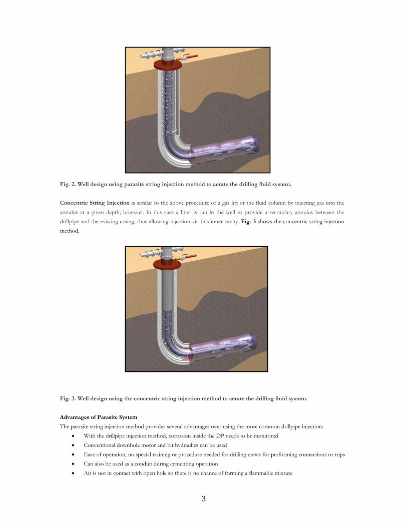
Fig. 2. Well design using parasite string injection method to aerate the drilling fluid system.
Concentric String Injection is similar to the above procedure of a gas lift of the fluid column by injecting gas into the annulus at a given depth; however, in this case a liner is run in the well to provide a secondary annulus between the drillpipe and the existing casing, thus allowing injection via this inner cavity. Fig. 3 shows the concentric string injection method.
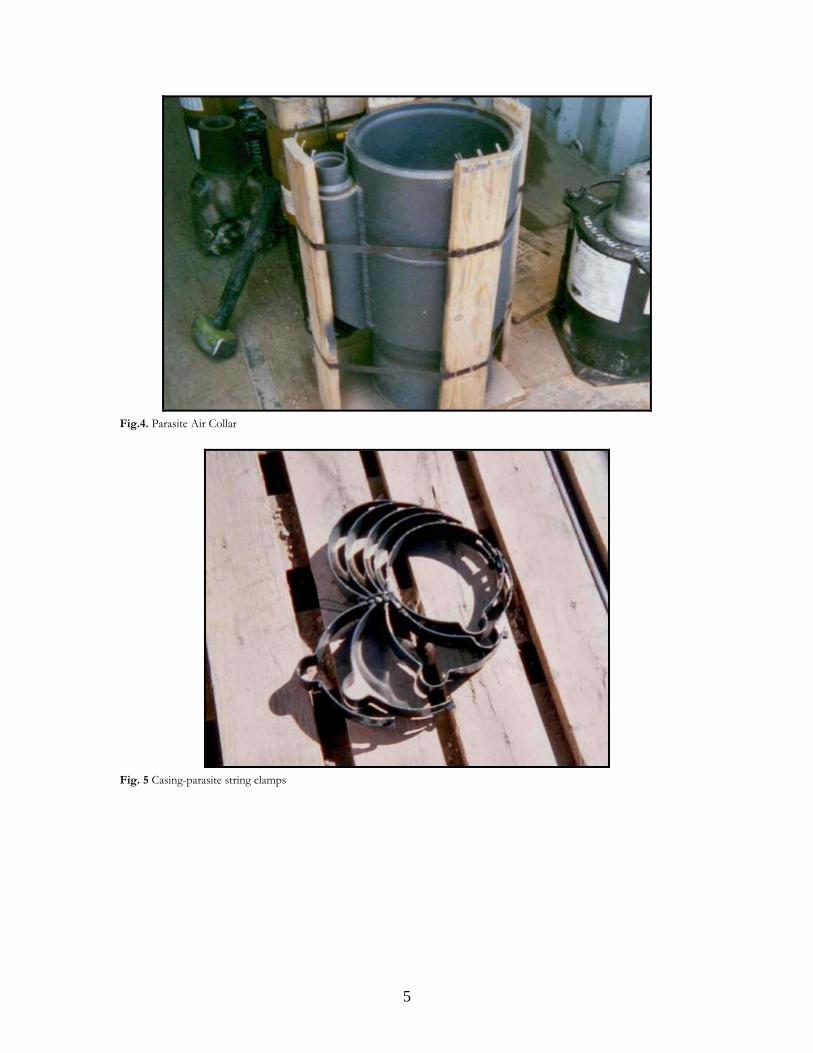
Fig. 3. Well design using the concentric string injection method to aerate the drilling fluid system.
Advantages of Parasite System
The parasite string injection method provides several advantages over using the more common drillpipe injection: • With the drillpipe injection method, corrosion inside the DP needs to be monitored • Conventional downhole motor and bit hydraulics can be used • Ease of operation, no special training or procedure needed for drilling crews for performing connections or trips • Can also be used as a conduit during cementing operation • Air is not in contact with open hole so there is no chance of forming a flammable mixture

4
• In addition to above advantages, the parasite string is a very economic way to utilize air injection benefits in Piceance Basin.
There are a few disadvantages associated with use of the parasite:
• The injection point of parasite string is a fixed point • The parasite point can be used only in the vertical section of the well • The pressure drawdown is a function of depth and volume of gas available on location • The drilling program has to incorporate a different well design • The biggest disadvantage is the parasite string is exposed to the formation while running the surface casing
where risk of parting the parasite string is there. • The parasite string injection ports are exposed to cement during cementing operations, precautions must be
taken to ensure the injection port is clear of cement fluid.
Installation measures related to parasite string
Planning is critical while running a parasite aerating string with a casing. It is of prime importance to provide extra handling precautions during the installation of a parasite string. The following steps are necessary to run the parasite string with casing:
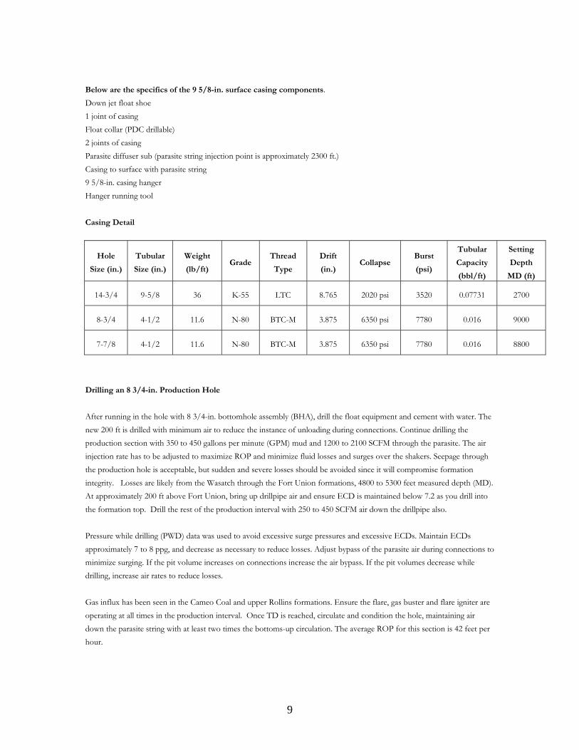
• Make up desired float equipment. • Run pre-determined amount of casing. • Rig up equipment to pick up parasite string. • Make up parasite air collar into casing string. • Make up upper casing joint in top of parasite air collar (Fig. 4). • Make up check valves in side pocket of parasite collar. • Make up first joint of parasite string into check valves. • Run in hole with casing and parasite string, making connections on parasite string when needed, pull parasite
string into notch in slip bowl when setting slips on casing. (Make sure all parasite string has been drifted. It is advisable to pump through the parasite string at pre-determined intervals while running in hole.) The parasite string should not fill going into the hole if the floats are holding.
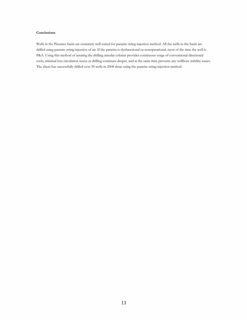
• Run casing and parasite string to desired depth, space out parasite string to a desirable height for surface pumping equipment. Use clamps to anchor parasite string to casing. Attached is Fig. 5 showing the casing-parasite string clamps.
• Pump through parasite string before starting cement job on casing. • Pump through the casing enough to establish circulation, monitor the parasite string during circulation to make
sure floats are holding. • Pump cement job. • After bumping plug on cement, pump a sugar water slug through parasite string to clear and prevent the cement
from setting up inside the parasite air collar ports.
5
Fig.4. Parasite Air Collar
Fig. 5 Casing-parasite string clamps

6
Drilling Program
The drilling prognosis for the wells drilled in the Piceance basin is shown in Fig. 6
Fig 6. Common drilling prognosis used on wells drilled in Piceance basin.

7
Fig 7. Typical well schematic of wells drilled in Piceance Basin.
Drilling 14 ¾-in. Surface Hole
Fig 7. shows the typical well schematic of wells drilled in Piceance Basin. Most of the wells are drilled on pad with five or twenty-two wells on each pad. This is crucial to make sure the latest directional plan is followed. Drilling close to the directional plan is needed to avoid interference with other wells on the pad. Massive losses are encountered in the surface section, be extremely cautious while drilling out with fluid to approximately 200 ft so the tools do not become stuck when these losses occur. Avoid high concentrations of phpa (not more than one quart per stand) to reduce slugging. To avoid erosion-related nonproductive time while drilling with air mist-foam system, extra elbow connections are used on the blooie line. Most of the wells are drilled with 14 3/4-in. to approximately 2700-ft TD (400 ft past the first red bed stringer). To provide optimum running of parasite string with 9-5/8 in., the maximum allowable inclination in a 14 3/4-in. surface hole is 10°, built at no more than 1.5°/100 dogleg severity (DLS). Drilling is carried out with water injecting 400 to 500 gpm, until losses are encountered. Then the drilling fluid system is changed to air mist-foam with 75 gpm and between 1800 to 2500

8
standard cubic feet per minute (SCFM) to minimize losses and maintain an equivalent circulation density (ECD) of less than 5 ppg till the TD is reached. Pumping 75 gpm provides motor lubrication and reduces vibrations. To optimize hole cleaning, higher rates of surfactant are injected as drilling reaches deeper depths. Average rate of penetration (ROP) for this section has been 35 fph.
Bit Specifics
Size IADC Type Jets Wt Surface
RPM
DH RPM GPM Air
SCFM
14.75 417 7 ×15 or 9 ×14
10 to 30 20 to 50 100 to 150 40 to 75 1800 to 2500
Cementing 9 5/8-in. casing with 1.9 in. parasite string
On average, ten hours are spent circulating and conditioning the surface hole and then pulling out of the hole. Running the casing with successful parasite installation is the single most important part in drilling the wells in Piceance basin. If the parasite is plugged or parted, most of the operators plug and abandon (P&A) the well and move to the next well. While running the casing, the integrity of the parasite string and diffuser sub is critical. Any upward movement of the casing will damage the parasite string. If ledges are encountered while running the casing, work through the ledges with circulation. Any attempt to rotate the casing will damage the parasite string. Once the casing shoe enters the red beds formation, cement the casing if continued progress cannot be made. Once the parasite string is run in the hole, take care not to kink it while bending it away from the wellhead. Fig. 8 shows the parasite string exiting the wellhead. After the casing is cemented, pump sugar water down the parasite string to clear the cement around the bottom part of the parasite. The average time to run and cement 9 5/8-in. casing is 30 hr.
Fig. 8. Parasite string exiting the wellhead.
9
Below are the specifics of the 9 5/8-in. surface casing components. Down jet float shoe 1 joint of casing Float collar (PDC drillable) 2 joints of casing Parasite diffuser sub (parasite string injection point is approximately 2300 ft.) Casing to surface with parasite string 9 5/8-in. casing hanger Hanger running tool
Casing Detail
Hole
Size (in.)
Tubular
Size (in.)
Weight
(lb/ft) Grade
Thread
Type
Drift
(in.) Collapse
Burst
(psi)
Tubular
Capacity
(bbl/ft)
Setting
Depth
MD (ft)
14-3/4 9-5/8 36 K-55 LTC 8.765 2020 psi 3520 0.07731 2700
8-3/4 4-1/2 11.6 N-80 BTC-M 3.875 6350 psi 7780 0.016 9000
7-7/8 4-1/2 11.6 N-80 BTC-M 3.875 6350 psi 7780 0.016 8800
Drilling an 8 3/4-in. Production Hole
After running in the hole with 8 3/4-in. bottomhole assembly (BHA), drill the float equipment and cement with water. The new 200 ft is drilled with minimum air to reduce the instance of unloading during connections. Continue drilling the production section with 350 to 450 gallons per minute (GPM) mud and 1200 to 2100 SCFM through the parasite. The air injection rate has to be adjusted to maximize ROP and minimize fluid losses and surges over the shakers. Seepage through the production hole is acceptable, but sudden and severe losses should be avoided since it will compromise formation integrity. Losses are likely from the Wasatch through the Fort Union formations, 4800 to 5300 feet measured depth (MD). At approximately 200 ft above Fort Union, bring up drillpipe air and ensure ECD is maintained below 7.2 as you drill into the formation top. Drill the rest of the production interval with 250 to 450 SCFM air down the drillpipe also. Pressure while drilling (PWD) data was used to avoid excessive surge pressures and excessive ECDs. Maintain ECDs approximately 7 to 8 ppg, and decrease as necessary to reduce losses. Adjust bypass of the parasite air during connections to minimize surging. If the pit volume increases on connections increase the air bypass. If the pit volumes decrease while drilling, increase air rates to reduce losses. Gas influx has been seen in the Cameo Coal and upper Rollins formations. Ensure the flare, gas buster and flare igniter are operating at all times in the production interval. Once TD is reached, circulate and condition the hole, maintaining air down the parasite string with at least two times the bottoms-up circulation. The average ROP for this section is 42 feet per hour.

10
Bit Specifics
Size Type Jets WOB RPM GPM DP Air
SCFM
Parasite Air
SCFM
8.75 PDC 5 × 13s
TFA .65 to .80
10 to 40 40 to 70 400 to 500 200 to 400 1200 to 2100
Cementing 4 1/2-in. casing Casing is not cemented all the way to the surface. Pumping an optimum amount of air down the parasite while circulation casing on bottom or while washing casing to bottom supported in minimizing losses. The goal is to maintain similar ECDs achieved during drilling for any operation performed after reaching the TD. Any tight sections that require reaming/back-reaming should be reamed using air via parasite at similar ECDs to minimize downhole losses. Suggested and Tested Air Injection Rates Down the Drillpipe (DP) and Parasite String vs. Depth
When drilling out of the shoe, it helps to run low-parasite air at 300 to 600 CFM to reduce the hole-unloading issue. 8 3/4-in. Production Hole
3,000 to 4,000 ft.
Drillpipe injection: 0 CFM Parasite string injection: 1,400 to 1,700 CFM Mud Pump: 500 GPM or more Bypass on connections: Bypassing 200-300 CFM maximum worked best, and less parasite air bypass worked better here. It is important to keep in mind that when mud is not circulating past the parasite sub, less air enters the annulus without making adjustments to the choke. Parasite air alone usually controls losses in this interval. The goal at this depth is to maintain the highest ROP, which is decreased by running drillpipe air. 4,000 to 5,000 ft.
Drillpipe injection: 250 CFM Parasite string injection: 1,700 to 1,800 CFM Mud pump: 500 GPM or more Bypass on connections: Actually bypassing 300 CFM maximum worked best, but less or no parasite air bypass worked better here. It is important to keep in mind that drillstring air is also being bypassed on connections. Fort Union formation is a heavy loss zone, and will be encountered in this interval. Normally, as the Fort Union top is approached, injection down the drillpipe with air also commences to lower ECD approximately 7.2., 300 ft above the Fort Union top to manage heavy losses when entering the formation top. 5,000 to 6,000 ft.
Drillpipe injection: 300 to 350 CFM Parasite string injection: 1,700 to 1,900 CFM Mud pump: 500 GPM Bypass on connections: Bypassing down to flow approximately 1400 CFM through the parasite worked best. It is important to keep in mind that drillstring air is also being bypassed on connections.

11
6,000 to 7,000 ft.
Drillpipe injection: 350 to 400 CFM Parasite string injection: 1,900 to 2,000 CFM Mud pump: 475 GPM. Flow rate may need to be reduced to keep injection pressure low enough (1,900 psi) to allow drillpipe air injection. Bypass on connections: Bypassing down to approximately 1,200 CFM through the parasite worked best. The zone from approximately 5,500 to 7,000 ft is interpreted as over-pressured but not actively producing gas. 7,000 to 8,000 ft.
Drillpipe injection: 350 to 400 CFM Parasite string injection: 1950 to 2000 CFM Mud pump output: 475 GPM. Flow rate may need to be reduced to keep injection pressure low enough (1900 psi) to allow drillpipe air injection. Bypass on connections: Bypassing down to approximately 1100 CFM through the parasite worked best. It is important to keep in mind that drillstring air is also being bypassed on connections. 8,000 to 9,000 ft.
Drillpipe injection: 450 CFM Parasite string injection: 2,000 CFM Mud pump output: approximately 470 GPM. Flow rate may need to be reduced to keep standpipe pressure (SPP) low enough (approximately 1,900 per square inch (psi) to allow drillpipe air injection. Bypass on connections: Bypassing down to approximately 1,100 CFM through the parasite worked best. It is important to keep in mind that drillstring air is also bypassed on connections. The zone from 7,000 ft to TD is over-pressured and is producing gas today. ECD values should be used only as a reference while monitoring total mud volume. Maintaining a consistent, fluctuation-free pit volume, even with 200-250 bbl/d mud losses is much more critical than trying to reach a target ECD. The PWD tool used is a useful real-time feedback loop to establish drilling and connection parameters, but associating the downhole pressure/ECD and drilling and connection parameters with fluctuation-free total mud volume will help with successful drilling even if the PWD tool fails downhole. It was useful to take note of what ECDs generated the lowest losses while drilling through lost circulation zones. Once these zones are up-hole of the PWD tool it is more important to maintain that ECD at the lost circulation zone, instead of trying to hold it at the bit or PWD tool. It was very important to make connections as fast as possible to reduce ECD fluctuation. Maintaining ECD at surface casing shoe at 4.5 to 5.5 ppg and ECD at bit between 6 to 7.5 ppg is the key to successfully drilling these wells with minimal losses. Multiphase modeling
Parasite air injection delivers a wider profile for ECD form bottom up to the shoe, ECD’s from 7000 ft and 9000 ft range from 6.7 to 7.3 ppg which is necessary to prevent instability of the hole, while achieving an ECD of 3 ppg just below the shoe to prevent loss of circulation on the upper zones as shown in fig. 9. On the other hand by direct injection (i.e. air + fluid injected down the drillstring) as shown in fig. 10 the range of ECD along the wellbore is reduced, showing 6.5 to 7.1 down the hole which is good for control the stability of the hole, but up hole at the shoe the minimum ECD achieved is 4.4 which is not sufficient to avoid loss of circulation.

12
Fig. 9. Using only parasite string injection, lower ECDs can be achieved along the entire wellbore.
Fig. 10. Using straight DP injection, lower ECDs were not achieved uphole of the wellbore.
13
Conclusions
Wells in the Piceance basin are extremely well-suited for parasite string injection method. All the wells in the basin are drilled using parasite string injection of air. If the parasite is dysfunctional or nonoperational, most of the time the well is P&A. Using this method of aerating the drilling annular column provides continuous usage of conventional directional tools, minimal loss circulation issues as drilling continues deeper, and at the same time prevents any wellbore stability issues. The client has successfully drilled over 50 wells in 2008 alone using the parasite string injection method.