a7v600-x motherboard - usp -...
TRANSCRIPT

Mot
herb
oardA7V600-X
User Guide
ii
Checklist
Copyright © 2005 ASUSTeK COMPUTER INC. All Rights Reserved.No part of this manual, including the products and software described in it, may bereproduced, transmitted, transcribed, stored in a retrieval system, or translated into anylanguage in any form or by any means, except documentation kept by the purchaser forbackup purposes, without the express written permission of ASUSTeK COMPUTER INC.(“ASUS”).
Product warranty or service will not be extended if: (1) the product is repaired, modified oraltered, unless such repair, modification of alteration is authorized in writing by ASUS; or (2)the serial number of the product is defaced or missing.
ASUS PROVIDES THIS MANUAL “AS IS” WITHOUT WARRANTY OF ANY KIND, EITHEREXPRESS OR IMPLIED, INCLUDING BUT NOT LIMITED TO THE IMPLIED WARRANTIESOR CONDITIONS OF MERCHANTABILITY OR FITNESS FOR A PARTICULAR PURPOSE.IN NO EVENT SHALL ASUS, ITS DIRECTORS, OFFICERS, EMPLOYEES OR AGENTS BELIABLE FOR ANY INDIRECT, SPECIAL, INCIDENTAL, OR CONSEQUENTIAL DAMAGES(INCLUDING DAMAGES FOR LOSS OF PROFITS, LOSS OF BUSINESS, LOSS OF USEOR DATA, INTERRUPTION OF BUSINESS AND THE LIKE), EVEN IF ASUS HAS BEENADVISED OF THE POSSIBILITY OF SUCH DAMAGES ARISING FROM ANY DEFECT ORERROR IN THIS MANUAL OR PRODUCT.
SPECIFICATIONS AND INFORMATION CONTAINED IN THIS MANUAL ARE FURNISHEDFOR INFORMATIONAL USE ONLY, AND ARE SUBJECT TO CHANGE AT ANY TIMEWITHOUT NOTICE, AND SHOULD NOT BE CONSTRUED AS A COMMITMENT BY ASUS.ASUS ASSUMES NO RESPONSIBILITY OR LIABILITY FOR ANY ERRORS ORINACCURACIES THAT MAY APPEAR IN THIS MANUAL, INCLUDING THE PRODUCTSAND SOFTWARE DESCRIBED IN IT.
Products and corporate names appearing in this manual may or may not be registeredtrademarks or copyrights of their respective companies, and are used only for identification orexplanation and to the owners’ benefit, without intent to infringe.
E1873
Revised Edition V2January 2005

iii
Fea
ture
s
ContentsNotices ............................................................................................ v
Safety information .......................................................................... vi
About this guide ............................................................................. vii
ASUS contact information ............................................................ viii
A7V600-X specifications summary ................................................. ix
Chapter 1: Product introduction1.1 Welcome! ........................................................................... 1-2
1.2 Package contents ............................................................... 1-2
1.3 Special Features ................................................................ 1-3
1.3.1 Product highlights ................................................... 1-3
1.3.2 Value-added solutions ............................................ 1-5
1.4 Motherboard components .................................................. 1-6
1.4.1 Core specifications ................................................. 1-7
1.5 Motherboard layout ............................................................ 1-9
1.6 Before you proceed .......................................................... 1-10
1.7 Motherboard installation ....................................................1-111.7.1 Placement direction ..............................................1-111.7.2 Screw holes ..........................................................1-11
1.8 Central Processing Unit (CPU) ......................................... 1-121.8.1 Installing the CPU ................................................ 1-12
1.9 System memory ............................................................... 1-131.9.1 DDR400 Qualified Vendor List ............................. 1-13
1.10 Expansion slots ................................................................ 1-14
1.10.1 Configuring an expansion card ........................... 1-141.10.2 Standard interrupt assignments ......................... 1-14
IRQ assignments for this motherboard ....................... 1-15
1.10.3 AGP slot ............................................................. 1-15
1.11 Jumpers ............................................................................ 1-16
1.12 Connectors ....................................................................... 1-18
Chapter 2: BIOS information2.1 Managing and updating your BIOS .................................... 2-2
2.1.1 Using ASUS EZ Flash to update the BIOS ............ 2-2

iv
Safeguards
Contents2.1.2 Using AFLASH to update the BIOS ....................... 2-42.1.3 Recovering the BIOS with CrashFree BIOS 2 ....... 2-7
2.2 BIOS Setup program .......................................................... 2-92.2.1 BIOS menu bar ...................................................... 2-92.2.2 Legend bar ........................................................... 2-10
2.3 Main Menu .........................................................................2-112.3.1 Primary and Secondary Master/Slave ................. 2-132.3.2 Keyboard Features .............................................. 2-15
2.4 Advanced Menu ............................................................... 2-162.4.1 Chip Configuration ............................................... 2-182.4.2 I/O Device Configuration ...................................... 2-202.4.3 PCI Configuration ................................................ 2-22
2.5 Power Menu ..................................................................... 2-232.5.1 Power Up Control ................................................ 2-252.5.2 Hardware Monitor ................................................ 2-26
2.6 Boot Menu ........................................................................ 2-27
2.7 Exit Menu ......................................................................... 2-29
Chapter 3: Software support3.1 Install an operating system................................................. 3-2
3.2 Support CD information ...................................................... 3-23.2.1 Running the support CD ........................................ 3-23.2.2 Drivers menu ......................................................... 3-33.2.3 Utilities menu ......................................................... 3-33.2.4 ASUS Contact Information ..................................... 3-4
3.3 ASUS Instant Music Lite ..................................................... 3-5
3.4 RAID 0 / RAID 1 / RAID 0 + 1 Configurations .................... 3-73.4.1 Install the Serial ATA (SATA) hard disks ................. 3-83.4.2 Enter VIA® Tech RAID BIOS Utility ........................ 3-93.4.3 Create Array ......................................................... 3-103.4.4 Delete Array ......................................................... 3-133.4.5 Select Boot Array ................................................. 3-133.4.6 Serial Number View ............................................. 3-14

v
Notices
Federal Communications Commission Statement
This device complies with Part 15 of the FCC Rules. Operation is subject tothe following two conditions:
• This device may not cause harmful interference, and
• This device must accept any interference received including interferencethat may cause undesired operation.
This equipment has been tested and found to comply with the limits for aClass B digital device, pursuant to Part 15 of the FCC Rules. These limitsare designed to provide reasonable protection against harmful interferencein a residential installation. This equipment generates, uses and can radiateradio frequency energy and, if not installed and used in accordance withmanufacturer’s instructions, may cause harmful interference to radiocommunications. However, there is no guarantee that interference will notoccur in a particular installation. If this equipment does cause harmfulinterference to radio or television reception, which can be determined byturning the equipment off and on, the user is encouraged to try to correct theinterference by one or more of the following measures:
• Reorient or relocate the receiving antenna.
• Increase the separation between the equipment and receiver.
• Connect the equipment to an outlet on a circuit different from that towhich the receiver is connected.
• Consult the dealer or an experienced radio/TV technician for help.
Canadian Department of Communications Statement
This digital apparatus does not exceed the Class B limits for radio noiseemissions from digital apparatus set out in the Radio InterferenceRegulations of the Canadian Department of Communications.
This class B digital apparatus complies with Canadian ICES-003.
The use of shielded cables for connection of the monitor to thegraphics card is required to assure compliance with FCC regulations.Changes or modifications to this unit not expressly approved by theparty responsible for compliance could void the user’s authority tooperate this equipment.

vi
Safety information
Electrical safety
• To prevent electrical shock hazard, disconnect the power cable fromthe electrical outlet before relocating the system.
• When adding or removing devices to or from the system, ensure thatthe power cables for the devices are unplugged before the signalcables are connected. If possible, disconnect all power cables from theexisting system before you add a device.
• Before connecting or removing signal cables from the motherboard,ensure that all power cables are unplugged.
• Seek professional assistance before using an adpater or extensioncord. These devices could interrupt the grounding circuit.
• Make sure that your power supply is set to the correct voltage in yourarea. If you are not sure about the voltage of the electrical outlet youare using, contact your local power company.
• If the power supply is broken, do not try to fix it by yourself. Contact aqualified service technician or your retailer.
Operation safety• Before installing the motherboard and adding devices on it, carefully
read all the manuals that came with the package.
• Before using the product, make sure all cables are correctly connectedand the power cables are not damaged. If you detect any damage,contact your dealer immediately.
• To avoid short circuits, keep paper clips, screws, and staples away fromconnectors, slots, sockets and circuitry.
• Avoid dust, humidity, and temperature extremes. Do not place theproduct in any area where it may become wet.
• Place the product on a stable surface.
• If you encounter technical problems with the product, contact aqualified service technician or your retailer.

vii
Where to find more informationRefer to the following sources for additional information and for productand software updates.
1. ASUS Websites
The ASUS websites worldwide provide updated information on ASUShardware and software products. The ASUS websites are listed in theASUS Contact Information on page viii.
2. Optional DocumentationYour product package may include optional documentation, such aswarranty flyers, that may have been added by your dealer. Thesedocuments are not part of the standard package.
About this guide
Conventions used in this guideTo make sure that you perform certain tasks properly, take note of thefollowing symbols used throughout this manual.
WARNING/DANGER: Information to prevent injury to yourselfwhen trying to complete a task.
CAUTION: Information to prevent damage to the componentswhen trying to complete a task.
IMPORTANT: Information that you MUST follow to complete atask.
NOTE: Tips and additional information to aid in completing a task.

viii
ASUS contact informationASUSTeK COMPUTER INC. (Asia-Pacific)Address 15 Li-Te Road, Peitou, Taipei, Taiwan 112Telephone +886-2-2894-3447Web site www.asus.com.twTechnical SupportTelephone(MB/Component) +886-2-2890-7121 (English) (Notebook) +886-2-2890-7122 (English) (Server/PC) +886-2-2890-7123 (English) (Networking) +886-2-2890-7902 (English)Support fax +886-2-2890-7698
ASUS COMPUTER INTERNATIONAL (America)Address 44370 Nobel Drive, Fremont, CA 94538, USAFax +1-510-608-4555E-mail [email protected] site usa.asus.comTechnical SupportTelephone (General) +1-502-995-0883 (Notebook) +1-510-739-3777Support fax +1-502-933-8713Support e-mail [email protected]
ASUS COMPUTER GmbH (Germany and Austria)Address Harkort Str. 25, D-40880 Ratingen, GermanyTelephone +49-2102-95990Fax +49-2102-959911Online contact www.asuscom.de/salesTechnical SupportTelephone +49-2102-95990Fax +49-2102-959911Online support www.asuscom.de/supportWeb site www.asuscom.de/news

ix
A7V600-X specifications summary
CPU
Chipset
Front Side Bus (FSB)
Memory
Expansion slots
Storage
Audio
LAN
Special Features
OverclockingFeatures
Back Panel I/O
Internal I/OConnectors
(continued on the next page)
Socket A for AMD Athlon XP/Athlon/Duron withThoroughbred/Barton Core support
Northbridge: VIA KT600Southbridge: VIA VT8237
400/333/266/200Mhz
3 x 184-pin DDR DIMM Sockets support a maximum of 3GBunbuffered non-ECC PC3200/2700/2100 DDR SDRAMmemory
1 x AGP 8X6 x PCI
2 x UltraDMA 133/100/662 x Serial ATA with RAID 0, RAID 1 and JBOD support
ADI AD1888 6-channel CODECS/PDIF out interface
Integrated 10/100 Mbps LAN controller
ASUS EZ FlashPower Loss RestartASUS C.O.P. (CPU Overheating Protection)ASUS CrashFree BIOS 2ASUS Instant Music Lite
ASUS JumperFreeASUS C.P.R. (CPU Parameter Recall)CPU Voltage adjustableSFS (Stepless Frequency Selection) from 100Mhz up to250MHz at 1MHz increment
1 x Parallel1 x Serial1 x PS/2 Keyboard1 x PS/2 Mouse1 x Audio I/O4 x USB 2.01 x RJ-45 Port1 x S/PDIF out port
CPU/Chassis FAN connectors20-pin ATX power connectorChassis IntrusionGAME/MIDI connectorCD/AUX audio inFront panel audio connector2 x USB 2.0 connector supports additional 4 USB 2.0 ports2 x Serial ATA port

x
A7V600-X specifications summary
BIOS features
Industry standard
Manageability
Form Factor
Support CD contents
* Specifications are subject to change without notice.
2Mb Flash ROM, ASUS Jumperfree, Award BIOS, PnP,DMI2.0, WfM2.0, SM BIOS2.3, ASUS EZ Flash, ASUSCrashFree BIOS 2, ASUS C.P.R.
PCI 2.2, USB 2.0
WfM 2.0. DMI 2.0, WOR, WOL, chassis intrusion
ATX form factor: 12 in x 9.6 in (30.5 cm x 24.5 cm)
Device driversASUS PC ProbeAnti-virus utilityASUS LiveUpdate Utility

1-1ASUS A7V600-X motherboard
This chapter gives information about the ASUSA7V600-X motherboard that came with thesystem.This chapter includes the motherboardlayout, jumper settings, and connector locations.
Mo
ther
bo
ard
Info
Chapter 1
1-2
1.1 Welcome!Thank you for buying the ASUS® A7V600-X motherboard!
The ASUS A7V600-X motherboard is loaded with the most advanced technologiesto deliver the maximum performance for socket A processors. Based on theadvanced VIA KT600 chipset with FSB 400 and DDR 400 support, the ASUSA7V600-X also features AGP 8X, Serial ATA, USB 2.0 as well as 6-channel audio,Fast Ethernet LAN and S/PDIF out features. Unique ASUS features such as ASUSC.O.P., C.P.R. , CrashFree BIOS2, and more are included to ensure the best userexperience and value in a motherboard.
Before you start installing the motherboard, and hardware devices on it, check theitems in your package with the list below.
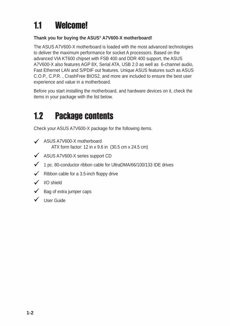
1.2 Package contentsCheck your ASUS A7V600-X package for the following items.
ASUS A7V600-X motherboardATX form factor: 12 in x 9.6 in (30.5 cm x 24.5 cm)
ASUS A7V600-X series support CD
1 pc. 80-conductor ribbon cable for UltraDMA/66/100/133 IDE drives
Ribbon cable for a 3.5-inch floppy drive
I/O shield
Bag of extra jumper caps
User Guide

1-3ASUS A7V600-X motherboard
1.3 Special features
1.3.1 Product highlights400 FSB K7 PlatformThe ASUS A7V600-X motherboard is loaded with the most advanced technologiesto deliver the maximum performance for socket A processors. Based on theadvanced VIA KT600 chipset with FSB 400 and DDR 400 support, the ASUSA7V600-X features AGP8X, Serial ATA, USB 2.0 as well as a 6-channel audioCODEC and Fast Ethernet LAN. Unique ASUS features such as ASUS C.O.P.,C.P.R. and more are included to ensure the best user experience and value in amotherboard.
400MHz FSB Athlon XP CPU supportAMD’s Athlon XP 3200+ and all follow-up CPUs now support 400MHz Front SideBus (FSB) for increased office productivity and enhanced digital media experience.
DDR400 (PC3200) supportDDR400 (PC3200), the latest and fastest DDR memory standard, supportsbandwidth up to 3.2 GB/s to provide enhanced system performance.(Note: PC3200 maximum to 2 DIMMs only. Visit the ASUS website for the latestqualified DDR400 module list.)
AGP 8X supportAGP 8X (AGP 3.0) is the next generation VGA interface specification that enablesenhanced graphics performance with high bandwidth speeds up to 2.12 GB/s. Witha bus of 533Mhz, AGP 8X is twice as fast as AGP 4X.
Serial ATA technologySerial ATA is the next generation ATA specification that provides scalableperformance for today and tomorrow. With up to 150MB/s data transfer rate, SATAis faster than current Parallel ATA, while providing 100% software compatibility.
8 USB 2.0 ports
USB 2.0 is the latest connectivity standard for next generation components andperipherals. USB 2.0 delivers fast transfer speeds up to 40 times faster at 480 MB/s, for easy connectivity and ultra-fast data transfers. The higher bandwidth of USB2.0 allows connection of devices such as high resolution video conferencingcameras, next generation scanners, printers, and fast storage units. USB 2.0 isbackward compatible with USB 1.1.

1-4
S/PDIF out port on Back I/O
The A7V600-X provides convenient connectivity to external home theater audiosystems via an S/PDIF out interface. Experience 5.1-channel surround sound andenhanced 3D audio while playing your favorite DVDs or games.
C.O.P. (CPU Overheating Protection):
With AMD® Athlon XP™ installed, the motherboard offers automatic CPUOverheating Protection to prolong the life of the entire system. If the CPUtemperature exceeds the set criteria, the PC shuts down automatically.
ASUS C.P.R. (CPU Parameter Recall)
The C.P.R. feature of the ASUS motherboard BIOS allows automatic resetting tothe BIOS previous settings in case the system hands due to overclocking. Whenthe system hangs due to overclocking, C.P.R. eliminates the need to open thesystem chassis and clear the RTC data. Simply reboot the system, and the BIOSautomatically restores the previous value of the CPU parameters.
CrashFree BIOS 2
The CrashFree BIOS 2 feature allows you to restore the original BIOS data fromthe ASUS support CD in case when the BIOS codes and data are corrupted. Thisprotection feature eliminates the need to buy a replacement ROM chip.
ASUS EZ Flash BIOS
With the ASUS EZ Flash, you can easily update the system BIOS even beforeloading the operating system. No need to use a DOS-based utility or boot from afloppy disk.
ASUS Instant Music LiteThrough this unique feature, the motherboard is conveniently designed to allowusers to enjoy their favorite music, without the need to enter Windows. (Thestickers on keyboard are separately purchased.)

1-5ASUS A7V600-X motherboard
1.3.2 Value-added solutionsOverclocking• adjustable CPU frequency multiple in BIOS using the ASUS JumperFree™
solution
• C.P.R. (CPU Parameter Recall)
• adjustable CPU VCORE voltages
• Stepless Frequency Selection (SFS) for fine-tuning system bus frequency from100MHz up to 250MHz at 1MHz increments
Temperature, fan, and voltage monitoringThe CPU temperature is monitored by the ASUS ASIC to prevent overheating anddamage. The system fan rotations per minute (RPM) is monitored for timely failuredetection. The system voltage levels are monitored to ensure stable supply ofcurrent for critical components.
Chassis intrusion detectionThe motherboard supports chassis intrusion monitoring. A chassis intrusion eventis retained in CMOS for more protection.
ASUS updateThis utility allows you to update the motherboard BIOS through a user-friendlyinterface. Connect to the Internet then to the ASUS FTP site nearest you to obtainthe latest BIOS version for your motherboard.

1-6 Chapter 1: Motherboard Information
1.4 Motherboard componentsBefore you install the motherboard, learn about its major components and availablefeatures to facilitate the installation and future upgrades. Refer to the succeedingpages for the component descriptions.
32
7
1
13
9
14
11
5
4
6
10
15
12
8
16
17
27
20
21
22
23
18 19
2526 24

ASUS A7V600-X Motherboard 1-7
1.4.1 Core specificationsCPU socket. Socket 462 (Socket A) surface mount, Zero Insertion Force(ZIF) socket for the AMD Athlon XP/Athlon/Duron Processors.(Note: When using CPUs with FSB 100, the maximum DDR data transferrate allowed is only at 266Mhz.)
North bridge controller. The VIA® KT600 supports AGP 8X mode, 400/333/266/200MHz Front Side Bus, and the latest 400/333/266MHz 64-bitmemory bus.
DDR DIMM sockets. These three 184-pin DIMM sockets support up to 3GBsystem memory using unbuffered non-ECC PC2700/2100 DDR DIMMs.(Note: PC3200 maximum to 2 DIMMs support only. Visit the ASUS website(www.asus.com) for the latest qualified DDR400 module list.)
IDE connectors. These dual-channel bus master IDE connectors supportup to four Ultra DMA133/100/66, PIO Modes 3 & 4 IDE devices. Both theprimary (blue) and secondary (black) connectors are slotted to preventincorrect insertion of the IDE ribbon cable.
ATX power connector. This 20-pin connector connects to an ATX +12Vpower supply. The power supply must have at least 1A on the +5V standbylead (+5VSB).
Floppy disk connector. This connector accommodates the providedribbon cable for the floppy disk drive. One side of the connector is slottedto prevent incorrect insertion of the floppy disk cable.
AGP slot. This Accelerated Graphics Port (AGP) slot supports 1.5VAGP8X mode graphics cards for 3D graphical applications.
Serial ATA connectors. These two 7-pin connectors accommodate the thincables for Serial ATA devices.
South bridge controller. The VIA® VT8237 integrated peripheral controllersupports various I/O functions including two Serial ATA ports, 2-channelATA/133 bus master IDE controller, up to eight USB 2.0 ports, LPC SuperI/O interface, AC’97 interface and PCI 2.2 interface.
Flash ROM. This 2Mb firmware contains the programmable BIOSprogram.
Standby power LED. This LED lights up if there is a standby power on themotherboard. This LED acts as a reminder to turn off the system powerbefore plugging or unplugging devices.
USB connectors. These two 10-1 pin connectors accomodates a USB 2.0module.
Super I/O controller. This Low Pin Count (LPC) interface provides thecommonly used Super I/O functionality. The chipset supports a high-performance floppy disk controller for a 360K/720K/1.44M/2.88M floppydisk drive, a multi-mode parallel port, two standard compatible UARTs, anda Flash ROM interface.
8
7
6
5
4
2
1
11
10
9
3
12
13

1-8 Chapter 1: Motherboard Information
PCI slots. These six 32-bit PCI 2.2 expansion slots support bus masterPCI cards like SCSI or LAN cards with 133MB/s maximum throughput.
Audio CODEC . The ADI 1888 is an AC’97 compliant audio CODEC forPC multimedia systems.
LAN controller. The Realtek 8201BL Fast Ethernet LAN controller deliverstransfer rates of up to 10/100Mbps Ethernet connections. Ideal for handlinglarge amounts of data such as video, audio and voice.
PS/2 mouse port. This green 6-pin connector is for a PS/2 mouse.
Parallel port. This 25-pin port connects a parallel printer, a scanner, orother devices.
RJ-45 port. This port allows connection to a Local Area Network (LAN)through a network hub.
Line In jack. This Line In (light blue) jack connects a tape player or otheraudio sources. In 6-channel mode, the function of this jack becomes Bass/Center speaker.
Line Out jack. This Line Out (lime) jack connects a headphone or aspeaker. In 6-channel mode, the function of this jack becomes FrontSpeaker Out.
Microphone. This Mic (pink) jack connects a microphone. In a 6-channelmode, the function of this jack becomes Rear Speaker Out.
15
16
17
18
19
20
21
22
14
23
24
25
26
27
USB 2.0 ports 3 and 4. These two 4-pin Universal Serial Bus (USB) portsare available for connecting USB 2.0 devices.
USB 2.0 ports 1 and 2. These two 4-pin Universal Serial Bus (USB) portsare available for connecting USB 2.0 devices.
Serial port (COM1). This 9-pin serial port is for an additional serial device.
S/PDIF out jack. This jack connects to external audio output devices.
PS/2 keyboard port. This purple 6-pin connector is for a PS/2 keyboard.
Connector Headphone/2-Speaker 4-Speaker 6-Speaker
Light Blue Line In Line In Bass/Center
Lime Line Out Front Speaker Out Front Speaker Out
Pink Mic In Rear Speaker Out Rear Speaker Out
Audio 2, 4 and 6-channel configuration

ASUS A7V600-X Motherboard 1-9
1.5 Motherboard layout24.5cm (9.6in)
30.5
cm (
12.0
in)
PCI1
PANEL
A7V600-X
®
CD
AUX
SuperI/O
4MbitLow PinCount
PS/2KBMST: MouseB: Keyboard
Below:Mic In
Center:Line Out
Top:Line In
Accelerated Graphics Port (AGP)
CPU_FAN
FP_AUDIO
AD1980CODEC
USB2.0T: USB4B: USB3
Top:RJ-45
GAME
CHASSIS
FLO
PP
Y
PR
I_ID
E
SE
C_I
DE
ATX
Pow
er C
onne
ctor
DD
R D
IMM
1 (6
4/72
bit,
184-
pin
mod
ule)
KBPWR
CHA_FAN
SB_PWR
VIAVT8237SouthBridge
USB56
CR2032 3VLithium Cell
CMOS Power
USBPW34
CLRTC
USBPW56
USB1USB2
PAR
AL
LE
L P
OR
T
SPDIF_O
COM1
PCI2
PCI3
PCI4
PCI5
PCI6
DD
R D
IMM
2 (6
4/72
bit,
184-
pin
mod
ule)
DD
R D
IMM
3 (6
4/72
bit,
184-
pin
mod
ule)
SATA1
OVER_VOLT1
USBPW12
Soc
ket 4
62VIA
KT600Chipset
USBPW78
USB78
SATA2
10/100LAN

1-10 Chapter 1: Motherboard Information
1.6 Before you proceedTake note of the following precautions before you install motherboard componentsor change any motherboard settings.
1. Unplug the power cord from the wall socket before touching anycomponent.
2. Use a grounded wrist strap or touch a safely grounded object or to a metalobject, such as the power supply case, before handling components toavoid damaging them due to static electricity.
3. Hold components by the edges to avoid touching the ICs on them.
4. Whenever you uninstall any component, place it on a grounded antistaticpad or in the bag that came with the component.
5. Before you install or remove any component, ensure that the ATXpower supply is switched off or the power cord is detached from thepower supply. Failure to do so may cause severe damage to themotherboard, peripherals, and/or components.
When lit, the green LED (SB_PWR) indicates that the system is ON, insleep mode, or in soft-off mode, a reminder that you should shut downthe system and unplug the power cable before removing or plugging inany motherboard component.
Install only 1.5V AGP cards on this motherboard to prevent damage toyour AGP card or motherboard.
A7V600-X
®
A7V600-X Onboard LED
SB_PWR
ONStandbyPower
OFFPowered
Off

ASUS A7V600-X Motherboard 1-11
1.7 Motherboard installationBefore you install the motherboard, study the configuration of your chassis toensure that the motherboard fits into it. The motherboard uses the ATX form factorthat measures 12 inches x 9.6 inches (30.5 cm x 24.5 cm).
1.7.1 Placement directionWhen installing the motherboard, make sure that you place it into the chassis inthe correct orientation. The edge with external ports goes to the rear part of thechassis as indicated in the image below.
1.7.2 Screw holesPlace nine (9) screws into the holes indicated by circles to secure the motherboardto the chassis.
Make sure to unplug the power cord before installing or removing themotherboard. Failure to do so may cause you physical injury and damagemotherboard components.
Do not overtighten the screws! Doing so may damage the motherboard.
Place this side towardsthe rear of the chassis

1-12 Chapter 1: Motherboard Information
1.8 Central Processing Unit (CPU)The motherboard provides a Socket A (462) for CPU installation. AMD processorsoffer gigahertz speeds to support all the latest computing platforms and applications.The A7V600-X supports AthlonTM XP, AMD AthlonTM, AMD Barton™ and AMD DuronTM
processors.
4. Once completely inserted, press the CPU firmly and close the socket lever until itsnaps shut.
5. Place the CPU fan and heatsink on the CPU. The heatsink should entirely coverthe CPU. Carefully attach the heatsink locking brace to the plastic clips on thesocket base. With the added weight of the CPU fan and heatsink locking brace,no extra force is required to keep the CPU in place
1.8.1 Installing the CPUFollow these steps to install a CPU:
1. Locate the Socket 462 and open it by pullingthe lever gently sideways away from thesocket. Then lift the lever upwards. Thesocket lever must be fully opened (90 to 100degrees).
2. Insert the CPU with the correct orientation.The notched or golden corner of the CPUmust be oriented toward the inner corner ofthe socket base nearest to the lever hinge.
The CPU should drop easily into place. Do not force the CPU into thesocket to avoid bending the pins. If the CPU does not fit, check itsalignment and look for bent pins.
A7V600-X
®
A7V600-X Socket A
AMD™ CPU
CPU NOTCH
LOCK
CPU NOTCHTO INNERCORNER
LEVER

ASUS A7V600-X Motherboard 1-13
1.9 System memoryThe motherboard has three Double Data Rate (DDR) DIMM sockets that supportsup to 3GB unbuffered non-ECC PC3200/2700/2100 DDR DIMMs.
A DDR DIMM has the same physical dimensions as an SDR DIMM, but it has a184-pin footprint compared to the 168-pin of the SDR DIMM. Also, a DDR DIMM issingle notched while an SDR DIMM is double notched.
A7V600-X
®
A7V600-X 184-Pin DDR DIMM Sockets
80 P
ins
104
Pin
s
DIM
M1
DIM
M2
DIM
M3
PC3200 maximum to 2 banks only.
A DDR DIMM is keyed with a notch so that it fits in only one direction. DO NOTforce a DIMM into a socket to avoid damaging the DIMM.
1.9.1 DDR400 Qualified Vendor ListThe following table lists the PC3200-DDR400 memory modules that have beentested and qualified for use with this motherboard. Make sure to use only thetested and qualified DDR400 DIMMs listed below.
1.9.1.2 DDR400 Two DIMM support only
1.9.1.1 DDR400 One DIMM support only Vendor Size Type P/N Chip
Samsung 512MB DS M368L6432ETM-CCC K4H560838E-TCCC
KingMax 512MB DS MPXC22D-38KT3R KDL388P4EA-50 Micron 256MB SS MT8VDDT3264AG-40BC4 MT46V32MTG-5BC
Micron 512MB DS MT16VDDT6464AG-40BC4 MT46V32M8TG-5BC
NANYA 512MB DS NT512D64S8HB1G-5T NT5DS32M8BT-5T
Infineon 512MB DS HYS64D64320GU-5-B HYB25D256800BT-5
Vendor Size Type P/N Chip
GEIL 512MB DS MAG16UL3264D1TG5A-KC GL3LC32G88TG-5A Micron 512MB DS MT16VDDT6464AG-40BC4 MT46V32M8TG-5BC Nanya 256MB SS NT256D64S88B1G-5T NT5DS32M8BT-5T
ADATA 256 SS MDOSS6F3G31JB1EAE K4H560838D-TCC4

1-14 Chapter 1: Motherboard Information
1.10.2 Standard Interrupt AssignmentsIRQ Priority Standard Function 0 1 System Timer 1 2 Keyboard Controller 2 N/A Programmable Interrupt 4* 12 Communications Port (COM1) 5* 13 Sound Card (sometimes LPT2) 6 14 Floppy Disk Controller 7* 15 Printer Port (LPT1) 8 3 System CMOS/Real Time Clock 9* 4 ACPI Mode when used10* 5 IRQ Holder for PCI Steering11* 6 IRQ Holder for PCI Steering12* 7 PS/2 Compatible Mouse Port13 8 Numeric Data Processor14* 9 Primary IDE Channel15* 10 Secondary IDE Channel
*These IRQs are usually available for ISA or PCI devices.
1.10 Expansion slotsThe A7V600-X motherboard has six (6) expansion PCI slots and one (1) AGP 8Xslot. The following sub-sections describe the slots and the expansion cards thatthey support.
1.10.1 Configuring an expansion cardAfter physically installing the expansion card, configure the card by adjusting thesoftware settings.
1. Turn on the system and change the necessary BIOS settings, if any.
2. Assign an IRQ to the card. Refer to the tables below.
3. Install the software drivers for the expansion card.

ASUS A7V600-X Motherboard 1-15
1.10.3 AGP slotThis motherboard has an Accelerated Graphics Port (AGP) slot that supports+1.5V AGP cards only. When you buy an AGP card, make sure that you ask forone with +1.5V specification. Note the notches on the card golden fingers toensure that they fit the AGP slot on your motherboard.
A7V600-X
®
A7V600-X Accelerated Graphics Port (AGP)
Keyed for 1.5v
IRQ assignments for this motherboard
A B C D E F G HPCI slot — — — shared — — — —PCI slot 2 shared — — — — — — —PCI slot 3 — shared — — — — — —PCI slot 4 — — shared — — — — —PCI slot 5 — — — shared — — — —PCI slot 6 shared — — — — — — —AGP slot shared — — — — — — —USB 1.1 UHCI 1 — — — — shared — — —USB 1.1 UHCI 2 — — — — shared — — —USB 1.1 UHCI 3 — — — — — shared — —USB 1.1 UHCI 4 — — — — — shared — —USB 2.0 EHCI — — — — — — shared —USB Device — — — — — — — sharedAC97 Codec — — — — — — shared —Onboard LAN — — shared — — — — —Onboard SATA — — — — shared — — —Onboard IDE — — — — shared — — —

1-16 Chapter 1: Motherboard Information
1. USB device wake-up (3-pin USBPW12, USBPW34, USBPW56, USBPW78)
Set these jumpers to +5V to wake up the computer from S1 sleep mode (CPUstopped, DRAM refreshed, system running in low power mode) using theconnected USB devices. Set to +5VSB to wake up from S3 sleep mode (nopower to CPU, DRAM in slow refresh, power supply in reduced power mode).All jumpers are set to pins 1-2 (+5V) by default because not all computers havethe appropriate power supply to support this feature.
The USBPW12 and USBPW34 jumpers are for the rear USB ports. TheUSBPW56 and USBPW78 jumpers are for the internal USB header that youcan connect to the front USB ports.
1. This feature requires a power supply that can provide at least 2Aon the +5VSB lead when these jumpers are set to +5VSB.Otherwise, the system does not power up.
2. The total current consumed must NOT exceed the power supplycapability (+5VSB) whether under normal or in sleep mode.
A7V600-X
®
A7V600-X USB Device Wake Up
USBPW12USBPW34
3221
+5V(Default)
+5VSB
USBPW78USBPW56
3221
+5V(Default)
+5VSB
2. Keyboard power (3-pin KBPWR)
This jumper allows you to enable or disable the keyboard wake-up feature. Setthis jumper to pins 2-3 (+5VSB) if you wish to wake up the computer when youpress a key on the keyboard (the default value is [Disabled]). This featurerequires an ATX power supply that can supply at least 1A on the +5VSB lead,and a corresponding setting in the BIOS (see section 4.5.1 Power Up Control).
A7V600-X
®
A7V600-X Keyboard Power Setting
(Default)+5V +5VSB
KBPWR2 31 2
1.11 Jumpers
ASUS A7V600-X Motherboard 1-17
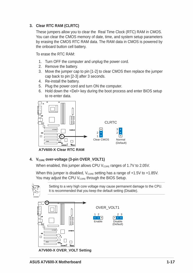
3. Clear RTC RAM (CLRTC)
These jumpers allow you to clear the Real Time Clock (RTC) RAM in CMOS.You can clear the CMOS memory of date, time, and system setup parametersby erasing the CMOS RTC RAM data. The RAM data in CMOS is powered bythe onboard button cell battery.
To erase the RTC RAM:
1. Turn OFF the computer and unplug the power cord.2. Remove the battery.3. Move the jumper cap to pin [1-2] to clear CMOS then replace the jumper
cap back to pin [2-3] after 3 seconds.4. Re-install the battery.5. Plug the power cord and turn ON the computer.6. Hold down the <Del> key during the boot process and enter BIOS setup
to re-enter data.
A7V600-X
®
A7V600-X Clear RTC RAM
CLRTC
NormalClear CMOS(Default)
12 2
3
4. VCORE over-voltage (3-pin OVER_VOLT1)
When enabled, this jumper allows CPU VCORE ranges of 1.7V to 2.05V.
When this jumper is disabled, VCORE setting has a range of +1.5V to +1.85V.You may adjust the CPU VCORE through the BIOS Setup.
Setting to a very high core voltage may cause permanent damage to the CPU.It is recommended that you keep the default setting (Disable).
21 2 3
A7V600-X
®
A7V600-X OVER_VOLT Setting
OVER_VOLT1
Enable(Default)Disable

1-18 Chapter 1: Motherboard Information
1.12 ConnectorsThis section describes and illustrates the connectors on the motherboard.
1. IDE connectors (40-1 pin PRI_IDE, SEC_IDE)
This connector supports the provided UltraDMA/133/100/66 IDE hard diskribbon cable. Connect the cable’s blue connector to the primary(recommended) or secondary IDE connector, then connect the gray connectorto the UltraDMA/133/100/66 slave device (hard disk drive) and the blackconnector to the UltraDMA/133/100/66 master device. It is recommended thatyou connect non-UltraDMA/133/100/66 devices to the secondary IDEconnector. If you install two hard disks, you must configure the second drive asa slave device by setting its jumper accordingly. Refer to the hard diskdocumentation for the jumper settings. BIOS supports specific device bootup.If you have more than two UltraDMA/133/100/66 devices, purchase anotherUltraDMA/133/100/66 cable. You may configure two hard disks to be bothmaster devices with two ribbon cables – one for the primary IDE connector andanother for the secondary IDE connector.
1. Pin 20 on each IDE connector is removed to match the covered hole on theUltraDMA cable connector. This prevents incorrect orientation when youconnect the cables.
2. The hole near the blue connector on the UltraDMA/133/100/66 cable isintentional.
For UltraDMA/133/100/66 IDE devices, use an 80-conductor IDE cable. TheUltraDMA/66 cable included in the motherboard package also supportsUltraDMA/133/100.
A7V600-X
®
A7V600-X IDE Connectors
NOTE: Orient the red markings(usually zigzag) on the IDEribbon cable to PIN 1.
SE
C_I
DE
PIN 1
PR
I_ID
E
PIN 1
ASUS A7V600-X Motherboard 1-19
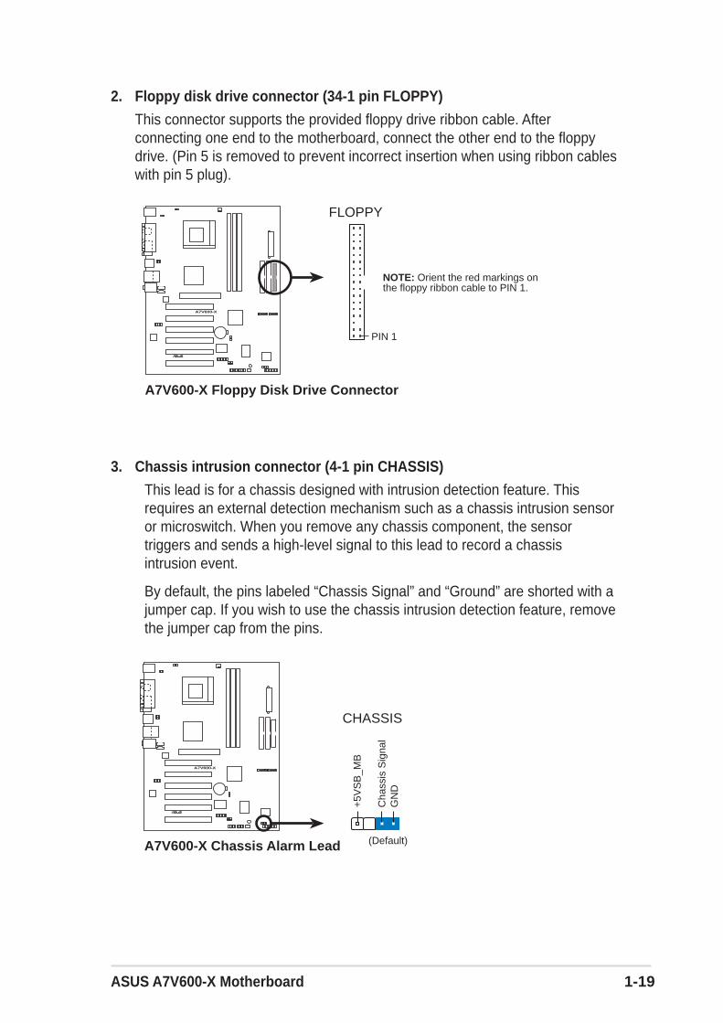
3. Chassis intrusion connector (4-1 pin CHASSIS)
This lead is for a chassis designed with intrusion detection feature. Thisrequires an external detection mechanism such as a chassis intrusion sensoror microswitch. When you remove any chassis component, the sensortriggers and sends a high-level signal to this lead to record a chassisintrusion event.
By default, the pins labeled “Chassis Signal” and “Ground” are shorted with ajumper cap. If you wish to use the chassis intrusion detection feature, removethe jumper cap from the pins.
A7V600-X
®
A7V600-X Chassis Alarm Lead
CHASSIS
+5V
SB
_MB
Cha
ssis
Sig
nal
GN
D
(Default)
2. Floppy disk drive connector (34-1 pin FLOPPY)
This connector supports the provided floppy drive ribbon cable. Afterconnecting one end to the motherboard, connect the other end to the floppydrive. (Pin 5 is removed to prevent incorrect insertion when using ribbon cableswith pin 5 plug).
A7V600-X
®
NOTE: Orient the red markings onthe floppy ribbon cable to PIN 1.
A7V600-X Floppy Disk Drive Connector
PIN 1
FLOPPY
1-20 Chapter 1: Motherboard Information
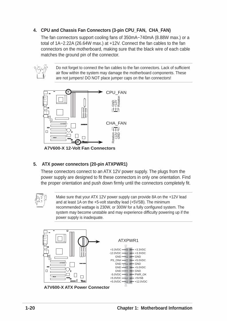
4. CPU and Chassis Fan Connectors (3-pin CPU_FAN, CHA_FAN)
The fan connectors support cooling fans of 350mA~740mA (8.88W max.) or atotal of 1A~2.22A (26.64W max.) at +12V. Connect the fan cables to the fanconnectors on the motherboard, making sure that the black wire of each cablematches the ground pin of the connector.
Do not forget to connect the fan cables to the fan connectors. Lack of sufficientair flow within the system may damage the motherboard components. Theseare not jumpers! DO NOT place jumper caps on the fan connectors!
A7V600-X
®
A7V600-X 12-Volt Fan Connectors
CPU_FAN
CHA_FAN
GN
D
Rot
atio
n+1
2VG
ND
Rot
atio
n+1
2V
5. ATX power connectors (20-pin ATXPWR1)
These connectors connect to an ATX 12V power supply. The plugs from thepower supply are designed to fit these connectors in only one orientation. Findthe proper orientation and push down firmly until the connectors completely fit.
Make sure that your ATX 12V power supply can provide 8A on the +12V leadand at least 1A on the +5-volt standby lead (+5VSB). The minimumrecommended wattage is 230W, or 300W for a fully configured system. Thesystem may become unstable and may experience difficulty powering up if thepower supply is inadequate.
A7V600-X
®
A7V600-X ATX Power Connector
ATXPWR1
+3.3VDC-12.0VDC
GNDPS_ON#
GNDGND
GND-5.0VDC+5.0VDC+5.0VDC
PWR_OK
+12.0VDC
+3.3VDC+3.3VDCGND
+5.0VDCGND+5.0VDC
GND
+5VSB
ASUS A7V600-X Motherboard 1-21
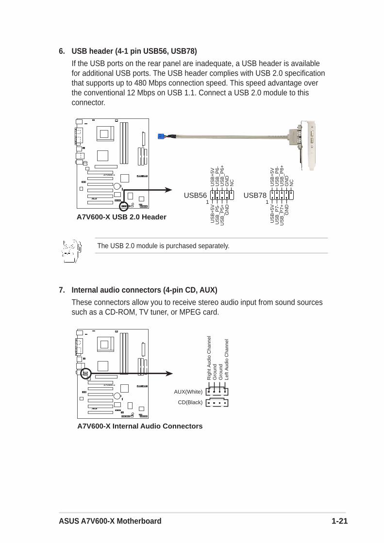
6. USB header (4-1 pin USB56, USB78)
If the USB ports on the rear panel are inadequate, a USB header is availablefor additional USB ports. The USB header complies with USB 2.0 specificationthat supports up to 480 Mbps connection speed. This speed advantage overthe conventional 12 Mbps on USB 1.1. Connect a USB 2.0 module to thisconnector.
A7V600-X
®
A7V600-X USB 2.0 Header
USB56
US
B+
5VU
SB
_P6-
US
B_P
6+G
ND
NC
US
B+
5VU
SB
_P5-
US
B_P
5+G
ND
1USB78
US
B+
5VU
SB
_P8-
US
B_P
8+G
ND
NC
US
B+
5VU
SB
_P7-
US
B_P
7+G
ND
1
7. Internal audio connectors (4-pin CD, AUX)
These connectors allow you to receive stereo audio input from sound sourcessuch as a CD-ROM, TV tuner, or MPEG card.
A7V600-X
®
A7V600-X Internal Audio Connectors
CD(Black)
AUX(White)
Rig
ht A
udio
Cha
nnel
Left
Aud
io C
hann
elG
roun
dG
roun
d
The USB 2.0 module is purchased separately.
1-22 Chapter 1: Motherboard Information
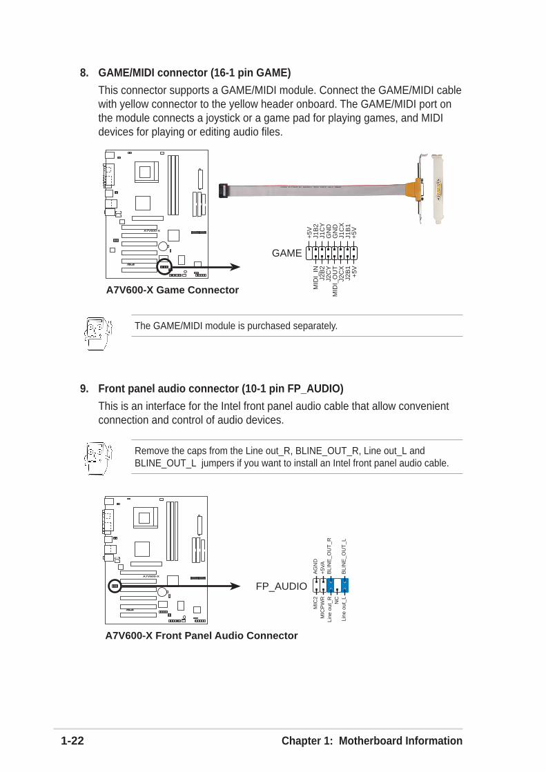
9. Front panel audio connector (10-1 pin FP_AUDIO)
This is an interface for the Intel front panel audio cable that allow convenientconnection and control of audio devices.
Remove the caps from the Line out_R, BLINE_OUT_R, Line out_L andBLINE_OUT_L jumpers if you want to install an Intel front panel audio cable.
A7V600-X
®
A7V600-X Front Panel Audio Connector
FP_AUDIO
BLI
NE
_OU
T_L
MIC
2
Line
out
_R
Line
out
_L
BLI
NE
_OU
T_R
NC
MIC
PW
R+
5VA
AG
ND
8. GAME/MIDI connector (16-1 pin GAME)
This connector supports a GAME/MIDI module. Connect the GAME/MIDI cablewith yellow connector to the yellow header onboard. The GAME/MIDI port onthe module connects a joystick or a game pad for playing games, and MIDIdevices for playing or editing audio files.
A7V600-X
®
A7V600-X Game Connector
GAME
+5V
+5V
J2B
1J2
CX
MID
I_O
UT
J2C
YJ2
B2
MID
I_IN
J1B
1J1
CX
GN
DG
ND
J1C
YJ1
B2
+5V
The GAME/MIDI module is purchased separately.
ASUS A7V600-X Motherboard 1-23
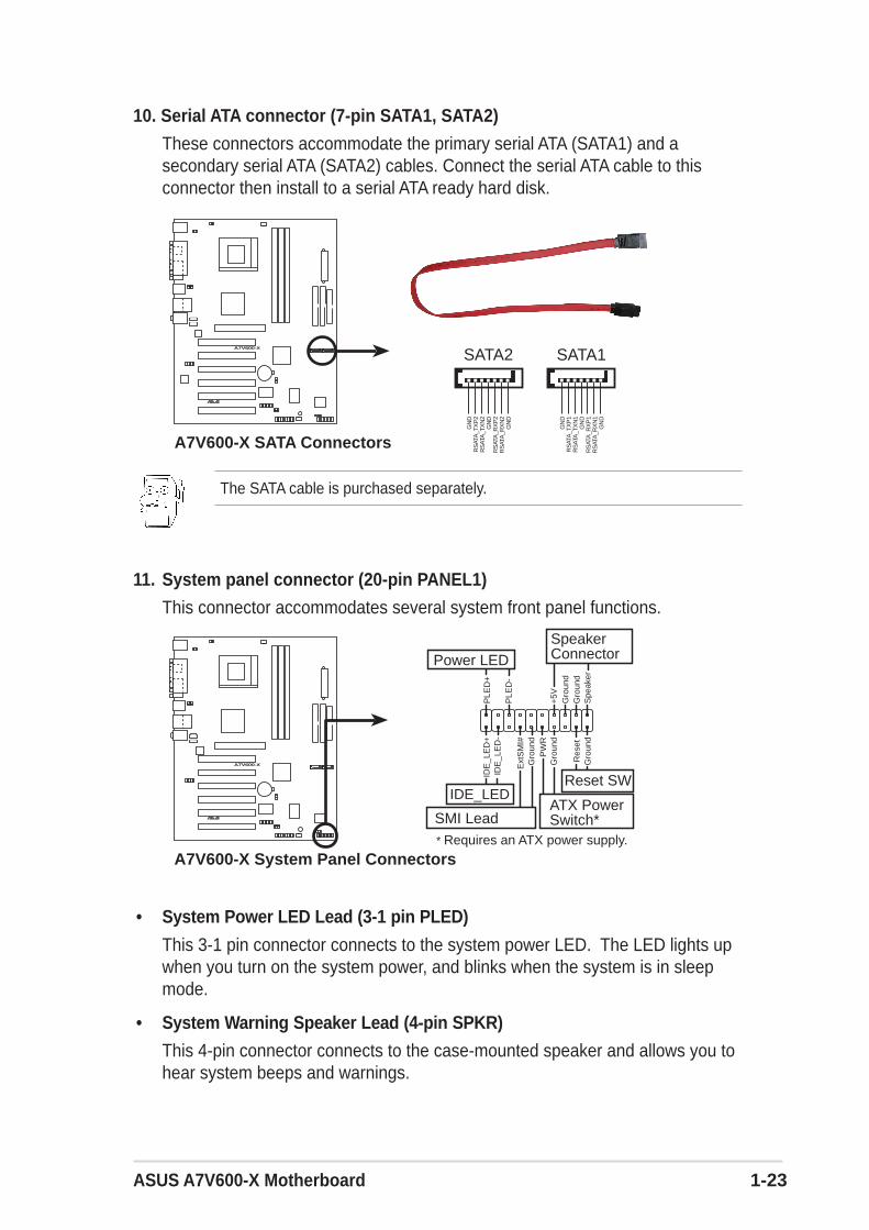
10. Serial ATA connector (7-pin SATA1, SATA2)
These connectors accommodate the primary serial ATA (SATA1) and asecondary serial ATA (SATA2) cables. Connect the serial ATA cable to thisconnector then install to a serial ATA ready hard disk.
A7V600-X
®
A7V600-X SATA ConnectorsG
ND
RS
ATA
_TX
P2
RS
ATA
_TX
N2
GN
DR
SAT
A_R
XP
2R
SAT
A_R
XN
2G
ND
SATA1
GN
DR
SAT
A_T
XP
1R
SAT
A_T
XN
1G
ND
RS
ATA
_RX
P1
RS
ATA
_RX
N1
GN
D
SATA2
11. System panel connector (20-pin PANEL1)
This connector accommodates several system front panel functions.
A7V600-X
®
A7V600-X System Panel Connectors* Requires an ATX power supply.
PLE
D-
Gro
und
PW
R+
5V Spe
aker
SpeakerConnectorPower LED
Gro
und
Reset SW
SMI Lead
Ext
SM
I#
Gro
und
Res
etG
roun
dG
roun
d
ATX PowerSwitch*
PLE
D+
IDE
_LE
D-
IDE
_LE
D+
IDE_LED
• System Power LED Lead (3-1 pin PLED)
This 3-1 pin connector connects to the system power LED. The LED lights upwhen you turn on the system power, and blinks when the system is in sleepmode.
• System Warning Speaker Lead (4-pin SPKR)
This 4-pin connector connects to the case-mounted speaker and allows you tohear system beeps and warnings.
The SATA cable is purchased separately.

1-24 Chapter 1: Motherboard Information
• Reset Switch Lead (2-pin RESET)
This 2-pin connector connects to the case-mounted reset switch for rebootingthe system without turning off the system power.
• ATX Power Switch/Soft-off Switch Lead (2-pin PWR)
This connector connects a switch that controls the system power. Pressing thepower switch turns the system between ON and SLEEP, or ON and SOFTOFF, depending on the BIOS or OS settings. Pressing the power switch whilein the ON mode for more than 4 seconds turns the system OFF.
• System Management Interrupt Lead (2-pin SMI)
This 2-pin connector allows you to manually place the system into a suspendmode, or “green” mode, where system activity is instantly decreased to savepower and to expand the life of certain system components. Attach the case-mounted suspend switch to this 2-pin connector.
• Hard Disk Activity Lead (2-pin IDE_LED)
This connector supplies power to the hard disk activity LED. The read or writeactivities of any device connected to the primary or secondary IDE connectorcause this LED to light up.

ASUS A7V600-X motherboard 2-1
This chapter tells how to change the systemsettings through the BIOS setup menus. Detaileddescriptions of the BIOS parameters are alsoprovided.
BIO
S In
form
atio
n
Chapter 2
2-2 Chapter 2: BIOS Information
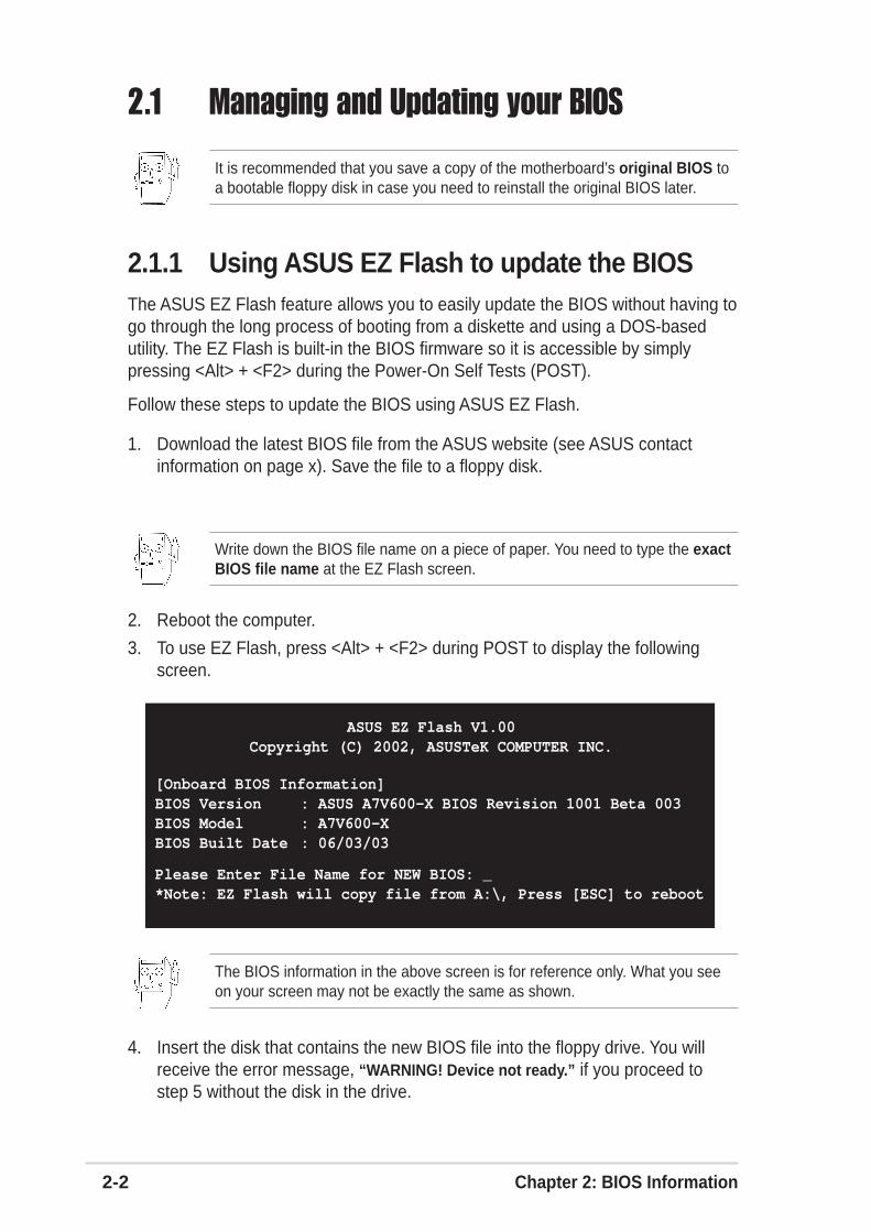
2.1.1 Using ASUS EZ Flash to update the BIOSThe ASUS EZ Flash feature allows you to easily update the BIOS without having togo through the long process of booting from a diskette and using a DOS-basedutility. The EZ Flash is built-in the BIOS firmware so it is accessible by simplypressing <Alt> + <F2> during the Power-On Self Tests (POST).
Follow these steps to update the BIOS using ASUS EZ Flash.
1. Download the latest BIOS file from the ASUS website (see ASUS contactinformation on page x). Save the file to a floppy disk.
2. Reboot the computer.
3. To use EZ Flash, press <Alt> + <F2> during POST to display the followingscreen.
4. Insert the disk that contains the new BIOS file into the floppy drive. You willreceive the error message, “WARNING! Device not ready.” if you proceed tostep 5 without the disk in the drive.
ASUS EZ Flash V1.00Copyright (C) 2002, ASUSTeK COMPUTER INC.
[Onboard BIOS Information]BIOS Version : ASUS A7V600-X BIOS Revision 1001 Beta 003BIOS Model : A7V600-XBIOS Built Date : 06/03/03
Please Enter File Name for NEW BIOS: _*Note: EZ Flash will copy file from A:\, Press [ESC] to reboot
It is recommended that you save a copy of the motherboard’s original BIOS toa bootable floppy disk in case you need to reinstall the original BIOS later.
Write down the BIOS file name on a piece of paper. You need to type the exactBIOS file name at the EZ Flash screen.
The BIOS information in the above screen is for reference only. What you seeon your screen may not be exactly the same as shown.
2.1 Managing and Updating your BIOS
ASUS A7V600-X motherboard 2-3
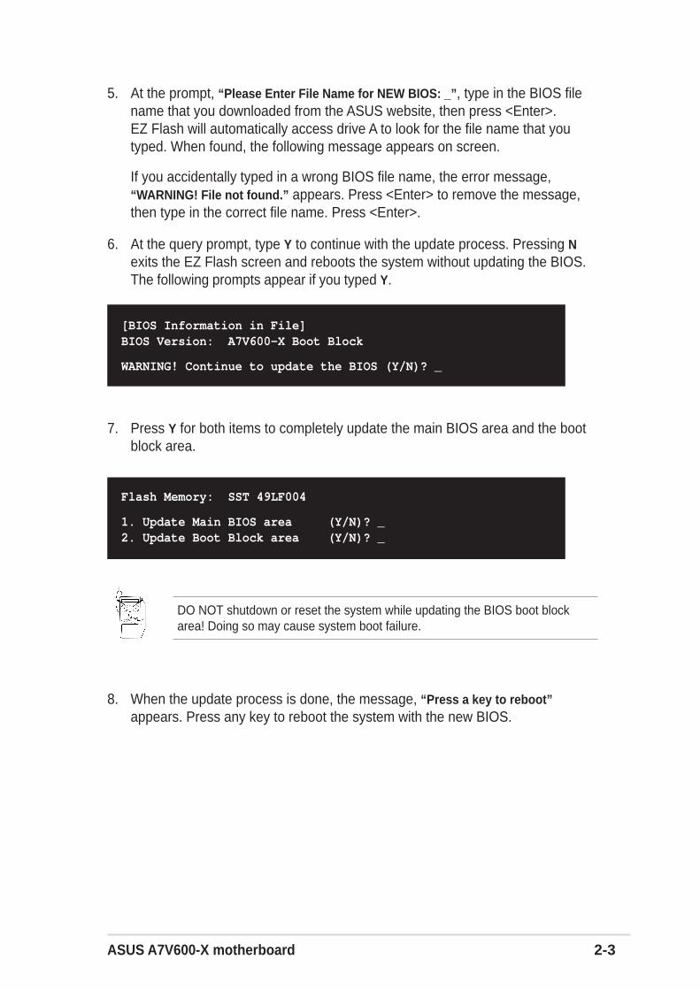
5. At the prompt, “Please Enter File Name for NEW BIOS: _”, type in the BIOS filename that you downloaded from the ASUS website, then press <Enter>.EZ Flash will automatically access drive A to look for the file name that youtyped. When found, the following message appears on screen.
If you accidentally typed in a wrong BIOS file name, the error message,“WARNING! File not found.” appears. Press <Enter> to remove the message,then type in the correct file name. Press <Enter>.
6. At the query prompt, type Y to continue with the update process. Pressing Nexits the EZ Flash screen and reboots the system without updating the BIOS.The following prompts appear if you typed Y.
7. Press Y for both items to completely update the main BIOS area and the bootblock area.
[BIOS Information in File]BIOS Version: A7V600-X Boot Block
WARNING! Continue to update the BIOS (Y/N)? _
8. When the update process is done, the message, “Press a key to reboot”appears. Press any key to reboot the system with the new BIOS.
Flash Memory: SST 49LF004
1. Update Main BIOS area (Y/N)? _2. Update Boot Block area (Y/N)? _
DO NOT shutdown or reset the system while updating the BIOS boot blockarea! Doing so may cause system boot failure.

2-4 Chapter 2: BIOS Information
The BIOS information in the above screen is for reference only. What you seeon your screen may not be exactly the same as shown.
2.1.2 Using AFLASH to update the BIOSCreating a bootable diskAFLASH.EXE is a Flash Memory Writer utility that updates the BIOS by uploadinga new BIOS file to the programmable flash ROM on the motherboard. This fileworks only in DOS mode. To determine the BIOS version of your motherboard,check the last four numbers of the code displayed on the upper left-hand corner ofyour screen during bootup. Larger numbers represent a newer BIOS file.
1. Type FORMAT A:/S at the DOS prompt to create a bootable system disk. DONOT copy AUTOEXEC.BAT and CONFIG.SYS to the disk.
2. Type COPY D:\AFLASH\AFLASH.EXE A:\ (assuming D is your CD-ROM drive)to copy AFLASH.EXE to the boot disk you created.
4. In DOS mode, type A:\AFLASH <Enter> to run AFLASH.
3. Reboot the computer from the floppy disk.
AFLASH works only in DOS mode. It does not work with certain memory driversthat may be loaded when you boot from the hard drive. It is recommended thatyou reboot using a floppy disk.
BIOS setup must specify “Floppy” as the first item in the boot sequence.
If the word “unknown” appears after Flash Memory:, the memory chip is eithernot programmable or is not supported by the ACPI BIOS and therefore, cannotbe programmed by the Flash Memory Writer utility.

ASUS A7V600-X motherboard 2-5
1. Download an updated ASUS BIOS file from the Internet (WWW or FTP) (seeASUS CONTACT INFORMATION on page x for details) and save to the bootfloppy disk you created earlier.
2. Boot from the floppy disk.
3. At the “A:\” prompt, type AFLASH and then press <Enter>.
4. At the Main Menu, type 2 then press <Enter>. The Update BIOS Including BootBlock and ESCD screen appears.
5. Type the filename of your new BIOS and the path, for example, A:\XXX-XX.XXX, then press <Enter>.
To cancel this operation, press <Enter>.
Updating the BIOS
5. Select 1. Save Current BIOS to File from the Main menu and press <Enter>.The Save Current BIOS To File screen appears.
6. Type a filename and the path, for example, A:\XXX-XX.XXX, then press<Enter>.
Update the BIOS only if you are sure that the new BIOS revision will solve yourproblems. Careless updating may result to more problems with themotherboard!
2-6 Chapter 2: BIOS Information
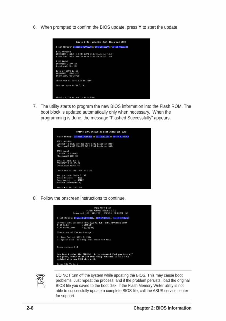
6. When prompted to confirm the BIOS update, press Y to start the update.
7. The utility starts to program the new BIOS information into the Flash ROM. Theboot block is updated automatically only when necessary. When theprogramming is done, the message “Flashed Successfully” appears.
8. Follow the onscreen instructions to continue.
DO NOT turn off the system while updating the BIOS. This may cause bootproblems. Just repeat the process, and if the problem persists, load the originalBIOS file you saved to the boot disk. If the Flash Memory Writer utility is notable to successfully update a complete BIOS file, call the ASUS service centerfor support.

ASUS A7V600-X motherboard 2-7
2.1.3 Recovering the BIOS with CrashFree BIOS 2The CrashFree BIOS 2 auto recovery tool allows you to restore BIOS from themotherboard support CD, or from a floppy disk that contains the BIOS file, in casethe current BIOS on the motherboard fails or gets corrupted.
To recover the BIOS from a floppy disk:
1. Boot the system.
2. When a corrupted BIOS is detected, the following screen message appears.
Bad BIOS checksum. Starting BIOS recovery...
Checking for floppy...
3. Insert a floppy disk that contains the original or the latest BIOS file for thismotherboard. If all the necessary files are found in the floppy disk, the BIOSupdate process continues.
Bad BIOS checksum. Starting BIOS recovery...
Checking for floppy...
Floppy found!
Reading file “A7V600-X.rom”. Completed.
Start flashing...
4. When the BIOS update process is complete, reboot the system.
1. Prepare the support CD that came with the motherboard or a floppy diskthat contains the motherboard BIOS before proceeding with the BIOSupdate process.
2. If you have saved a copy of the original motherboard BIOS to a bootablefloppy disk, you may also use this disk to restore the BIOS. See section“4.1.1 Creating a bootable floppy disk.”
DO NOT shutdown or reset the system while updating the BIOS! Doing so maycause system boot failure!

2-8 Chapter 2: BIOS Information
To recover the BIOS from the support CD:
1. Boot the system.
2. When a corrupted BIOS is detected, the following screen message appears.
Bad BIOS checksum. Starting BIOS recovery...
Checking for floppy...
3. Place the support CD in the CD-ROM. The support CD contains the originalBIOS for this motherboard.
4. When the BIOS update process is complete, reboot the system.
Bad BIOS checksum. Starting BIOS recovery...
Checking for floppy...
Floppy not found!
Checking for CD-ROM...
CD-ROM found.
Reading file “A7V600-X.rom”. Completed.
Start flashing...
If there is no floppy disk found in the drive, the system automatically checks theCD-ROM.
DO NOT shutdown or reset the system while updating the BIOS! Doing so maycause system boot failure!
The recovered BIOS may not be the latest BIOS version for this motherboard.Visit ASUS website (www.asus.com) to download the latest BIOS file.

ASUS A7V600-X motherboard 2-9
2.2 BIOS Setup programUse the BIOS Setup program when you are installing a motherboard, reconfiguringyour system, or prompted to “Run Setup”. This section explains how to configureyour system using this utility.
Even if you are not prompted to use the Setup program, you may want to change theconfiguration of your computer in the future. For example, you may want to enablethe security password feature or make changes to the power management settings.This requires you to reconfigure your system using the BIOS Setup program so thatthe computer can recognize these changes and record them in the CMOS RAM ofthe EEPROM.
The EEPROM on the motherboard stores the Setup utility. When you start up thecomputer, the system provides you with the opportunity to run this program. Press<Delete> during the Power-On Self Test (POST) to enter the Setup utility, otherwise,POST continues with its test routines.
The Setup program is designed to make it as easy to use as possible. It is a menu-driven program, which means you can scroll through the various sub-menus andmake your selections among the predetermined choices.
Because the BIOS software is constantly being updated, the following BIOSsetup screens and descriptions are for reference purposes only, and may notexactly match what you see on your screen.
2.2.1 BIOS menu barThe top of the screen has a menu bar with the following selections:
MAIN Use this menu to make changes to the basic systemconfiguration.
ADVANCED Use this menu to enable and make changes to the advancedfeatures.
POWER Use this menu to configure and enable Power Managementfeatures.
BOOT Use this menu to configure the default system device used tolocate and load the Operating System.
EXIT Use this menu to exit the current menu or to exit the Setupprogram.
To access the menu bar items, press the right or left arrow key on the keyboarduntil the desired item is highlighted.

2-10 Chapter 2: BIOS Information
2.2.2 Legend barAt the bottom of the Setup screen is a legend bar. The keys in the legend bar allowyou to navigate through the various setup menus. The following table lists the keysfound in the legend bar with their corresponding functions.
Navigation Key(s) Function Description<F1> or <Alt + H> Displays the General Help screen from anywhere in
the BIOS Setup
<Esc> Jumps to the Exit menu or returns to the main menufrom a sub-menu
Left or Right arrow Selects the menu item to the left or right
Up or Down arrow Moves the highlight up or down between fields
- (minus key) Scrolls backward through the values for the high-lighted field
+ (plus key) or spacebar Scrolls forward through the values for the highlightedfield
<Enter> Brings up a selection menu for the highlighted field
<Home> or <PgUp> Moves the cursor to the first field
<End> or <PgDn> Moves the cursor to the last field
<F5> Resets the current screen to its Setup Defaults
<F10> Saves changes and exits Setup
General helpIn addition to the Item Specific Help window, the BIOS setup program also providesa General Help screen. You may launch this screen from any menu by simply pressing<F1> or the <Alt> + <H> combination. The General Help screen lists the legend keysand their corresponding functions.
Saving changes and exiting the Setup programSee “2.7 Exit Menu” for detailed information on saving changes and exiting the setupprogram.
When a scroll bar appears to the right of a help window, it indicates that there is moreinformation to be displayed that will not fit in the window. Use <PgUp> and <PgDn>or the up and down arrow keys to scroll through the entire help document. Press<Home> to display the first page, press <End> to go to the last page. To exit the helpwindow, press <Enter> or <Esc>.

ASUS A7V600-X motherboard 2-11
2.3 Main MenuWhen you enter the Setup program, the following screen appears.
Sub-menu Note that a right pointer symbol (as shown onthe left) appears to the left of certain fields. This pointerindicates that you can display a sub-menu from this field.A sub-menu contains additional options for a fieldparameter. To display a sub-menu, move the highlightto the field and press <Enter>. The sub-menu appears.Use the legend keys to enter values and move fromfield to field within a sub-menu as you would within amenu. Use the <Esc> key to return to the main menu.Take some time to familiarize yourself with the legendkeys and their corresponding functions. Practicenavigating through the various menus and sub-menus.
If you accidentally make unwanted changes to any ofthe fields, use the set default hot key <F5> to load the Setup default values. Whilemoving around through the Setup program, note that explanations appear in the ItemSpecific Help window located to the right of each menu. This window displays thehelp text for the currently highlighted field.
System Time [XX:XX:XX]Sets the system to the time that you specify (usually the current time). The formatis hour, minute, second. Valid values for hour, minute and second are Hour: (00 to23), Minute: (00 to 59), Second: (00 to 59). Use the <Tab> or <Shift> + <Tab> keysto move between the hour, minute, and second fields.
System Date [XX/XX/XXXX]Sets the system to the date that you specify (usually the current date). The formatis month, day, year. Valid values for month, day, and year are Month: (1 to 12),Day: (1 to 31), Year: (up to 2099). Use the <Tab> or <Shift> + <Tab> keys to movebetween the month, day, and year fields.
2-12 Chapter 2: BIOS Information
Legacy Diskette A, B [1.44M, 3.5 in.]Sets the type of floppy drive installed. Configuration options: [None] [360K, 5.25in.] [1.2M , 5.25 in.] [720K , 3.5 in.] [1.44M, 3.5 in.] [2.88M, 3.5 in.]
Floppy 3 Mode Support [Disabled]This is required to support older Japanese floppy drives. The Floppy 3 Mode featureallows reading and writing of 1.2MB (as opposed to 1.44MB) on a 3.5-inch diskette.Configuration options: [Disabled] [Enabled]
Language [English US]This field allows you to choose the BIOS language version from the availableoptions.
Chassis Intrusion Detection [Disabled]This field allows you to enable or disable the chassis intrusion detection feature.
Supervisor Password [Disabled] / User Password [Disabled]These fields allow you to set passwords. To set a password, highlight theappropriate field and press <Enter>. Type in a password then press <Enter>. Youcan type up to eight alphanumeric characters. Symbols and other characters areignored. To confirm the password, type the password again and press <Enter>.The password is now set to [Enabled]. This password allows full access to theBIOS Setup menus. To clear the password, highlight this field and press <Enter>.The same dialog box as above appears. Press <Enter>. The password is set to[Disabled].
Make a copy of the original BIOS on a bootable floppy disk before settingpasswords. You will need to upload the BIOS file in case you erase the CMOSRAM in the future.
A note about passwordsThe BIOS Setup program allows you to specify passwords in the Main menu. The passwordscontrol access to the BIOS during system startup. Passwords are not case sensitive, meaning,passwords typed in either uppercase or lowercase letters are accepted. The BIOS Setup programallows you to specify two different passwords: a Supervisor password and a User password. Ifyou did not set a Supervisor password, anyone can access the BIOS Setup program. If youdid, the Supervisor password is required to enter the BIOS Setup program and to gain fullaccess to the configuration fields.
Forgot the password?If you forget your password, you can clear it by erasing the CMOS Real Time Clock (RTC)RAM. The RAM data containing the password information is powered by the onboard buttoncell battery. If you need to erase the CMOS RAM, unplug the all the power cables and removethe button cell battery. Re-install the battery after about 2 seconds, then power up the system.Refer to section “2.1 Managing and updating your BIOS” on how to update the BIOS.

ASUS A7V600-X motherboard 2-13
2.3.1 Primary and Secondary Master/Slave
Type [Auto]Select [Auto] to automatically detect an IDE hard disk drive. If automatic detectionis successful, Setup automatically fills in the correct values for the remaining fieldson this sub-menu. If automatic detection fails, select [User Type HDD] to manuallyenter the IDE hard disk drive parameters. Refer to the next section for details.
[User Type HDD]
Manually enter the number of cylinders, heads and sectors per track for the drive.Refer to the drive documentation or label for this information.
Before attempting to configure a hard disk drive, make sure you have the correctconfiguration information supplied by the drive manufacturer.
Halt On [All Errors]This field specifies the types of errors that will cause the system to halt.Configuration options: [All Errors] [No Error] [All but Keyboard] [All but Disk] [All butDisk/Keyboard]
Installed Memory [XXX MB]This field automatically displays the amount of conventional memory detected bythe system during the boot process.
2-14 Chapter 2: BIOS Information
If no drive is installed or if you are removing a drive and not replacing it, select[None].
Other options for the Type field are:
[CD-ROM] - for IDE CD-ROM drives
[LS-120] - for LS-120 compatible floppy disk drives
[ZIP] - for ZIP-compatible disk drives
[MO] - for IDE magneto optical disk drives
[Other ATAPI Device] - for IDE devices not listed here
After making your selections on this sub-menu, press the <Esc> key to return tothe Main menu. When the Main menu appears, the hard disk drive field displaysthe size for the hard disk drive that you configured.
Translation Method [LBA]Select the hard disk drive type in this field. When Logical Block Addressing (LBA)is enabled, the 28-bit addressing of the hard drive is used without regard forcylinders, heads, or sectors. Note that LBA Mode is necessary for drives with morethan 504MB storage capacity. Configuration options: [LBA] [LARGE] [Normal][Match Partition Table] [Manual]
CylindersThis field configures the number of cylinders. Refer to the drive documentation todetermine the correct value. To make changes to this field, set the Type field to[User Type HDD] and the Translation Method field to [Manual].
HeadThis field configures the number of read/write heads. Refer to the drivedocumentation to determine the correct value. To make changes to this field, setthe Type field to [User Type HDD] and the Translation Method field to [Manual].
SectorThis field configures the number of sectors per track. Refer to the drivedocumentation to determine the correct value. To make changes to this field, setthe Type field to [User Type HDD] and the Translation Method field to [Manual].
CHS CapacityThis field shows the drive’s maximum CHS capacity as calculated by the BIOSbased on the drive information you entered.
Maximum LBA CapacityThis field shows the drive’s maximum LBA capacity as calculated by the BIOSbased on the drive information you entered.

ASUS A7V600-X motherboard 2-15
SMART Monitoring [Disabled]This field allows you to enable or disable the S.M.A.R.T. (Self-Monitoring, Analysisand Reporting Technology) system that utilizes internal hard disk drive monitoringtechnology. This parameter is normally disabled because the resources used in theSMART monitoring feature may decrease system performance. Configurationoptions: [Disabled] [Enabled]
PIO Mode [4]This option lets you set a PIO (Programmed Input/Output) mode for the IDEdevice. Modes 0 through 4 provide successive increase in performance.Configuration options: [0] [1] [2] [3] [4]
Ultra DMA Mode [Disabled]Ultra DMA capability allows improved transfer speeds and data integrity forcompatible IDE devices. Set to [Disabled] to suppress Ultra DMA capability. Tomake changes to this field, set the Type field to [User Type HDD]. Configurationoptions: [0] [1] [2] [3] [4] [5] [6] [Disabled]
Multi-Sector Transfers [Maximum]This option automatically sets the number of sectors per block to the highestnumber that the drive supports. Note that when this field is automaticallyconfigured, the set value may not always be the fastest value for the drive. Youmay also manually configure this field. Refer to the documentation that came withthe hard drive to determine the optimum value and set it manually. To makechanges to this field, set the Type field to [User Type HDD]. Configuration options:[Disabled] [2 Sectors] [4 Sectors] [8 Sectors] [16 Sectors] [32 Sectors] [Maximum]
2.3.2 Keyboard Features
Boot Up NumLock Status [On]This field enables users to activate the Number Lock function upon system boot.Configuration options: [Off] [On]
Keyboard Auto-Repeat Rate [12/Sec]This controls the speed at which the system registers repeated keystrokes.Options range from 6 to 30 characters per second. Configuration options: [6/Sec][8/Sec] [10/Sec] [12/Sec] [15/Sec] [20/Sec] [24/Sec] [30/Sec]

2-16 Chapter 2: BIOS Information
Keyboard Auto-Repeat Delay [1/4 Sec]This field sets the time interval for displaying the first and second characters.Configuration options: [1/4 Sec] [1/2 Sec] [3/4 Sec] [1 Sec]
2.4 Advanced Menu
CPU SpeedThis displays the current speed of the CPU installed.
CPU Frequency MultipleThis field displays frequency multiple value between the CPU’s internal frequency(CPU speed) and external frequency.
CPU External Frequency (MHz)This feature tells the clock generator what frequency to send to the system busand PCI bus. The bus frequency (external frequency) multiplied by the bus multipleequals the CPU speed.
Memory Frequency (MHz)This field determines the memory clock frequency. Configuration options: [Auto][266] [333] [400].
CPU VCore Setting [Auto]The [Manual] setting allows you to manually select the core voltagesupplied to the CPU (see next item). It is recommended that you keep thedefault setting [Auto] to allow the system to automatically determine theappropriate CPU core voltage.
CPU VCoreWhen the CPU VCore Setting parameter above is set to [Manual], theCPU VCore item allows you to select a specific CPU core voltage. Thisfield is not accessible when the CPU VCore Setting is set to [Auto].
ASUS A7V600-X motherboard 2-17
CPU Level 1 Cache, CPU Level 2 Cache [Enabled]These fields allow you to choose from the default [Enabled] or choose [Disabled] toturn on or off the CPU Level 1 and Level 2 built-in cache. Configuration options:[Disabled] [Enabled]
PS/2 Mouse Function Control [Auto]The default setting [Auto] allows the system to detect a PS/2 mouse at startup. If amouse is detected, the BIOS assigns IRQ12 to the PS/2 mouse. Otherwise, IRQ12can be used for expansion cards. When you set this field to [Enabled], BIOSreserves IRQ12, whether or not a PS/2 mouse is detected at startup. Configurationoptions: [Enabled] [Auto]
USB Legacy Support [Auto]This motherboard supports Universal Serial Bus (USB) devices. The default of[Auto] allows the system to detect a USB device at startup. If detected, the USBcontroller legacy mode is enabled. If not detected, the USB controller legacy modeis disabled.
When you set this field to [Disabled], the USB controller legacy mode is disabledwhether or not you are using a USB device. Configuration options: [Disabled][Enabled] [Auto]
OS/2 Onboard Memory > 64M [Disabled]When using OS/2 operating systems with installed DRAM of greater than 64MB,you need to set this option to [Enabled]. Otherwise, leave to the default setting[Disabled]. Configuration options: [Disabled] [Enabled]
Instant Music [Disabled]Allows you to enable or disable the Instant Music feature in BIOS.Configuration options: [Disabled] [Enabled]
Instant Music CD ROMAllows you to select the CD-ROM drive that you wish to use for the Instant MusicCD playback. Configuration options depends on the optical drives installed on yoursystem.
The above item appears only if you enabled the Instant Music item.
When Instant Music is enabled, the PS/2 keyboard power up feature isautomatically disabled.

2-18 Chapter 2: BIOS Information
SDRAM Configuration [By SPD]This parameter allows you to set the optimal timings for items 2–5, depending onthe memory modules that you are using. The default setting is [By SPD], whichconfigures items 2–5 by reading the contents in the SPD (Serial Presence Detect)device. The EEPROM on the memory module stores critical information about themodule, such as memory type, size, speed, voltage interface, and module banks.Configuration options: [User Defined] [By SPD]
The SDRAM parameters (items 2~5) become configurable only when you setthe SDRAM Configuration to [User Defined].
2.4.1 Chip Configuration
SDRAM CAS Latency (value depends on SDRAM SPD)
This item controls the latency between the SDRAM read command and the timethe data actually becomes available. Configuration options: [1.5T] [2T] [2.5T]
SDRAM RAS to CAS Delay (value depends on SDRAM SPD)
This item controls the latency between the DDR SDRAM active command and theread/write command. Configuration options: [5T] [4T] [3T] [2T].
SDRAM RAS Precharge Delay (value depends on SDRAM SPD)
This item controls the idle clocks after issuing a precharge command to the DDRSDRAM. Configuration options: [5T] [4T] [3T] [2T]
SDRAM Active Precharge Delay (value depends on SDRAM SPD)
This item controls the number of DDR SDRAM clocks used for DDR SDRAMparameters. Configuration options: [9T] [8T] [7T] [6T]
SDRAM 1T Command ControlConfiguration options: [Disabled] [Enabled] [Auto]

ASUS A7V600-X motherboard 2-19
SDRAM Bank InterleaveConfiguration options: [Disabled] [2 Bank] [4 Bank] [Auto]
Graphics Aperture Size [64MB]This feature allows you to select the size of mapped memory for AGP graphic data.Configuration options: [4MB] [8MB] [16MB] [32MB] [64MB] [128MB] [256MB][512MB] [1024MB]
The [1024MB] and [512MB] configuration options are available onlywhen you use AGP 8X graphics card.
AGP Capability [8X Mode]This motherboard supports the AGP 8X interface that enables enhanced graphicsperformance with high bandwidth speeds up to 2.12GB/s. AGP8X is backward-compatible. When set to [1X Mode], the AGP interface only provides a peak datathroughput of 266MB/s even if you are using an AGP 8X card.Configuration options: [Auto] [1X Mode] [2X Mode] [4X Mode] [8X Mode]
AGP Drive Strength [Auto]Configuration options: [Auto] [Manual]
Configuration options: [0][1][2][3][4][5][6][7][8][9][A][B][C][D][E][F]
AGP performance control [Disabled]Configuration options: [Disabled] [Enabled]
AGP Fast Write control [Disabled]Configuration options: [Disabled] [Enabled]
Video Memory Cache Mode [UC]USWC (uncacheable, speculative write combining) is a new cache technology forthe video memory of the processor. It can greatly improve the display speed bycaching the display data. You must set this to UC (uncacheable) if your displaycard does not support this feature, otherwise the system may not boot.Configuration options: [UC] [USWC]
DRAM Burst Length 8QW [Disabled]This item enables or disables the DRAM Burst Length 8QW. Configuration options:[Disabled] [Auto]
Rank Interleave [Disabled]This item enables or disables the rank interleave item. Configuration options:[Disabled] [Auto]

2-20 Chapter 2: BIOS Information
2.4.2 I/O Device Configuration
Onboard FDC Swap A & BThese fields set option to switch drive letter assignments. Configuration Options:[No Swap] [Swap AB]
Floppy Disk Access Control [R/W]When set to [Read Only], this item protects files from being copied to floppy disksby allowing reads from, but not writes to, the floppy disk drive. The default setting[R/W] allows both reads and writes. Configuration options: [R/W] [Read Only]
Onboard Serial Port 1 [3F8H/IRQ4]This field allows you to set the address for the onboard serial connector.Configuration options: [3F8H/IRQ4] [2F8H/IRQ3] [3E8H/IRQ4] [2E8H/IRQ10][Disabled]
Onboard Parallel Port [378H/IRQ7]This field allows you to set the address of the onboard parallel port connector. Ifyou disable this field, the Parallel Port Mode and ECP DMA Select configurationsare not available. Configuration options: [Disabled] [378H/IRQ7] [278H/IRQ5]
Parallel Port Mode [ECP+EPP]This field allows you to set the operation mode of the parallel port. [Normal] allowsnormal-speed operation but in one direction only; [EPP] allows bidirectional parallelport operation; [ECP] allows the parallel port to operate in bidirectional DMA mode;[ECP+EPP] allows normal speed operation in a two-way mode. Configurationoptions: [Normal] [EPP] [ECP] [ECP+EPP]

ASUS A7V600-X motherboard 2-21
ECP DMA Select [3]This field allows you to configure the parallel port DMA channel for the selectedECP mode. This selection is available only if you select [ECP] or [ECP+EPP] inParallel Port Mode above. Configuration options: [1] [3]
Onboard Game Port [200H-207H]These fields allow you to set the addresses for the onboard game connectors.Game ports must have different addresses. Configuration options: [200H/207H][208H-20FH] [Disabled]
Onboard MIDI I/O [Disabled]These fields allow you to set the addresses for the onboard MIDI connectors. MIDIports must have different addresses. Configuration options: [330H-331H] [300H-301H] [Disabled]
USB Controller [Enabled]These fields allow you to enable or disable the onboard USBcontroller.Configuration options: [Disabled] [Enabled]
USB Device Mode [Disabled]These fields allow you to enable or disable the USB device mode Configurationoptions: [Disabled] [Enabled]
Onboard PCI IDE [Both]These fields allow you to select or disable the onboard PCI IDE drive for use.Configuration options: [Both] [Primary] [Secondary] [Disabled]
Onboard LAN [Enabled]These fields allow you to enable or disable the onboard LAN controller.Configuration options: [Disabled] [Enabled]
Onboard LAN Boot ROM [Enabled]These fields allow you to enable or disable the onboard LAN boot ROM.Configuration options: [Disabled] [Enabled]
Onboard ATA Boot ROM [Enabled]These fields allow you to enable or disable the onboard Serial ATA controller bootROM. Configuration options: [Disabled] [Enabled]
Onboard AC97 Audio Controller [Auto]These fields allow you to disable or set to auto detect the onboard AC97 audiocontroller.Configuration options: [Auto] [Disabled]

2-22 Chapter 2: BIOS Information
2.4.3 PCI Configuration
Slot 1/5, Slot 2/6, Slot 3, Slot 4 IRQ [Auto]These fields automatically assign the IRQ for each PCI slot. The default setting foreach field is [Auto], which utilizes auto-routing to determine IRQ assignments.Configuration options: [Auto] [NA] [3] [4] [5] [7] [9] [10] [11] [12] [14] [15]
PCI/VGA Palette Snoop [Disabled]Some non-standard VGA cards, like graphics accelerators or MPEG video cards,may not show colors properly. Setting this field to [Enabled] corrects this problem.If you are using standard VGA cards, leave this field to the default setting[Disabled]. Configuration options: [Disabled] [Enabled]
PCI Latency Timer [32]Leave this field to the default setting [32] for best performance and stability.
PCI Delayed Transaction [Disabled]This field enables or disables the PCI delayed transaction function. Configurationoptions: [Disabled] [Enabled]
Primary VGA BIOS [PCI VGA Card]This field allows you to select the primary graphics card. Configuration options:[PCI VGA Card] [AGP VGA Card]
Onboard ATA device First [No]This field allows you to select the onboard ATA first.Configuration options: [No] [Yes]

ASUS A7V600-X motherboard 2-23
PCI IRQ Resource Exclusion
2.5 Power MenuThe Power menu allows you to reduce power consumption. This feature turns offthe video display and shuts down the hard disk after a period of inactivity.
IRQ XX Reserved [No/ICU]These fields indicate whether or not the displayed IRQ for each field is being usedby a legacy (non-PnP) ISA card. The setting [No/ICU] for an IRQ field indicates thatyou are using the ISA Configuration Utility (ICU), and that this particular IRQ isNOT required by a legacy ISA card. Set the IRQ field to [Yes] if you install a legacyISA card that requires a unique IRQ and you are NOT using ICU. Configurationoptions: [No/ICU] [Yes]
Power Management [User Defined]This field allows you to activate or deactivate the automatic power saving features.When set to [Disabled], the power management features do not functionregardless of the other settings on this menu. The [User Defined] option allows youto set the period of inactivity before the system enters suspend mode. Refer to“Suspend Mode” later in this section.
When set to [Max Saving], system power is conserved to its greatest amount. Thissetting automatically puts the system into suspend mode after a brief period ofsystem inactivity. [Min Saving] allows the least power saving as the system enterssuspend mode only after a long period of inactivity. Configuration options: [UserDefined] [Disabled] [Min Saving] [Max Saving]

2-24 Chapter 2: BIOS Information
Even if installed, your screen saver does not display when you select [BlankScreen] for the above field.
[V/H SYNC+Blank] blanks the screen and turns off vertical and horizontalscanning. Configuration options: [Blank Screen] [V/H SYNC+Blank] [DPMSStandby] [DPMS Suspend] [DPMS OFF] [DPMS Reduce ON]
HDD Power Down [Disabled]Shuts down any IDE hard disk drives in the system after a period of inactivity asset in this user-configurable field. This feature does not affect SCSI hard drives.Configuration options: [Disabled] [1 Min] [2 Min] [3 Min]...[15 Min]
ACPI Suspend To RAM [Disabled]This field allows you to enable or disable the ACPI Suspend-to-RAM feature. Tosupport this feature, the +5VSB of the power supply should have the capacity toprovide more than 720mA current. Configuration options: [Disabled] [Enabled]
Suspend Mode [Disabled]Sets the time period before the system goes into suspend mode. Configurationoptions: [Disabled] [1~2 Min] [2~3 Min] [4~5 min] [8~9 Min] [20 Min] [30 Min]
PWR Button < 4 Secs [Soft Off]When set to [Soft off], the ATX switch can be used as a normal system power-offbutton when pressed for less than 4 seconds. [Suspend] allows the button to havea dual function where pressing less than 4 seconds puts the system in sleep mode.Regardless of the setting, holding the ATX switch for more than 4 seconds powersoff the system. Configuration options: [Soft off] [Suspend]
You should install the Advanced Power Management (APM) utility to keep thesystem time updated even when the computer enters suspend mode. InWindows 3.x and Windows 95, you need to install Windows with the APMfeature. In Windows 98 or later, APM is automatically installed as indicated by abattery and power cord icon labeled “Power Management” in the Control Panel.Select the item “Advanced” in the Power Management Properties dialog box.
Video Off Option [Suspend -> Off ]This field determines when to activate the video off feature for monitor powermanagement. Configuration options: [Always On] [Suspend -> Off]
Video Off Method [DPMS OFF]This field defines the video off features. The Display Power Management System(DPMS) feature allows the BIOS to control the video display card if it supports theDPMS feature. [Blank Screen] only blanks the screen. Use this for monitors withoutpower management or “green” features.

ASUS A7V600-X motherboard 2-25
2.5.1 Power Up Control
AC Power Loss Restart [Disabled]This allows you to set whether or not to reboot the system after powerinterruptions. [Disabled] leaves your system off while [Enabled] reboots thesystem. [Previous State] sets the system back to the state it was before the powerinterruption. Configuration options: [Disabled] [Enabled] [Previous State]
Wake/Power Up On External Modem [Disabled]This allows either settings of [Enabled] or [Disabled] for powering up the computerwhen the external modem receives a call while the computer is in Soft-off mode.Configuration options: [Disabled] [Enabled]
Wake/Power On By PS/2 Keyboard [Disabled]This parameter allows you to use specific keys on the keyboard to turn on thesystem. This feature requires an ATX power supply that provides at least 1A on the+5VSB lead. Configuration options: [Disabled] [Space Bar] [Ctrl-Esc] [Power Key]
Wake/Power On By PS/2 Mouse [Disabled]When set to [Double Click], this parameter allows you to use the PS/2 mouse toturn on the system. This feature requires an ATX power supply that provides atleast 1A on the +5VSB lead. Configuration options: [Disabled] [Double Click]
Power Up On PCI Card [Disabled]When set to [Enabled], this parameter allows you to turn on the system through aPCI LAN or modem card. This feature requires an ATX power supply that providesat least 1A on the +5VSB lead.Configuration options: [Disabled] [Enabled]
Automatic Power Up [Disabled]This allows an unattended or automatic system power up. You may configure yoursystem to power up at a certain time of the day by selecting [Everyday] or at acertain time and day by selecting [By Date]. Configuration options: [Disabled][Everyday] [By Date]
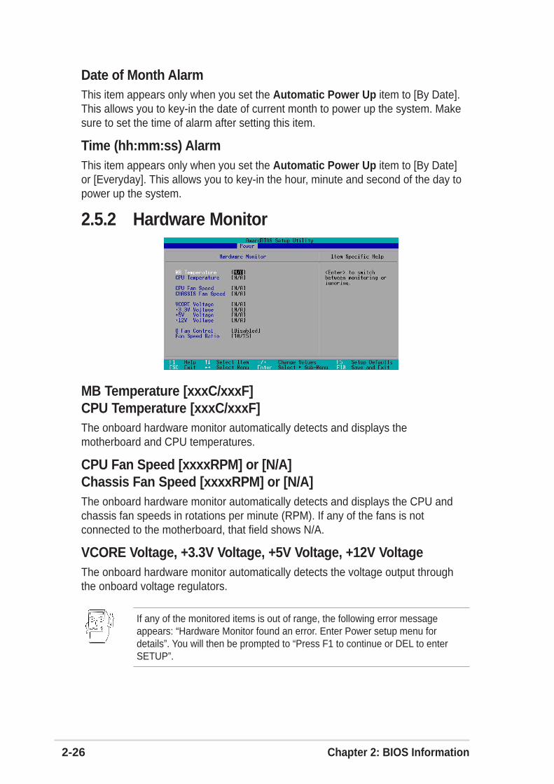
2-26 Chapter 2: BIOS Information
2.5.2 Hardware Monitor
MB Temperature [xxxC/xxxF]CPU Temperature [xxxC/xxxF]The onboard hardware monitor automatically detects and displays themotherboard and CPU temperatures.
CPU Fan Speed [xxxxRPM] or [N/A]Chassis Fan Speed [xxxxRPM] or [N/A]The onboard hardware monitor automatically detects and displays the CPU andchassis fan speeds in rotations per minute (RPM). If any of the fans is notconnected to the motherboard, that field shows N/A.
VCORE Voltage, +3.3V Voltage, +5V Voltage, +12V VoltageThe onboard hardware monitor automatically detects the voltage output throughthe onboard voltage regulators.
If any of the monitored items is out of range, the following error messageappears: “Hardware Monitor found an error. Enter Power setup menu fordetails”. You will then be prompted to “Press F1 to continue or DEL to enterSETUP”.
Date of Month AlarmThis item appears only when you set the Automatic Power Up item to [By Date].This allows you to key-in the date of current month to power up the system. Makesure to set the time of alarm after setting this item.
Time (hh:mm:ss) AlarmThis item appears only when you set the Automatic Power Up item to [By Date]or [Everyday]. This allows you to key-in the hour, minute and second of the day topower up the system.

ASUS A7V600-X motherboard 2-27
2.6 Boot Menu
Boot SequenceThe Boot menu allows you to select four types of boot devices using the up and downarrow keys. By using the <+> or <Space> key, you can promote devices and by usingthe <-> key, you can demote devices. Promotion or demotion of devices alters thepriority which the system uses to boot device on system power up. Configurationfields include Removable Devices, IDE Hard Drive, ATAPI CD-ROM, and Other BootDevice.
Removable Device [Legacy Floppy]Configuration options: [Disabled] [Legacy Floppy] [LS-120] [ZIP] [ATAPI�MO] [USBFDD] [USB ZIP/Flash]
IDE Hard DriveThis field allows you to select which IDE hard disk drive to use in the bootsequence. Pressing [Enter] will show the product IDs of all connected IDE harddisk drives.
ATAPI CD-ROMThis field allows you to select which ATAPI CD-ROM drive to use in the bootsequence. Pressing [Enter] will show the product IDs of all your connected ATAPICD-ROM drives.
Other Boot Device [INT18 Device (Network)]Configuration options: [Disabled] [SCSI Boot Device] [INT18 Device (Network)]
Plug & Play O/S [No]This field allows you to use a Plug-and-Play (PnP) operating system to configurethe PCI bus slots instead of using the BIOS. When [Yes] is selected, interrupts maybe reassigned by the OS. If you installed a non-PnP OS or if you want to preventreassigning of interrupt settings, keep the default setting [No]. Configurationoptions: [No] [Yes]

2-28 Chapter 2: BIOS Information
Reset Configuration Data [No]The Extended System Configuration Data (ESCD) contain information about non-PnP devices. It also holds the complete record of how the system was configuredthe last time it was booted. Select [Yes] if you want to clear these data during thePower-On-Self-Test (POST). Configuration options: [No] [Yes]
Boot Virus Detection [Enabled]This field allows you to set boot virus detection, ensuring a virus-free boot sector.The system halts and displays a warning message when it detects a virus. If thisoccurs, you can either allow the operation to continue or use a virus-free bootablefloppy disk to restart and investigate your system. Configuration options: [Disabled][Enabled]
Quick Power On Self Test [Enabled]This field speeds up the Power-On-Self Test (POST) routine by skipping retesting asecond, third, and fourth time. Configuration options: [Disabled] [Enabled]
Boot Up Floppy Seek [Enabled]When enabled, the BIOS will seek the floppy disk drive to determine whether thedrive has 40 or 80 tracks. Configuration options: [Disabled] [Enabled]
Full Screen Logo [Enabled]This allows you to enable or disable the full screen logo display feature.Configuration options: [Disabled] [Enabled]
Interrupt Mode [APIC]The Advanced Programmable Interrupt Controller (APIC) setting allows you todistribute interrupt routings other than the 16 IRQs. The Programmable InterruptController (PIC) setting allows you to use the 16 IRQs only. Configuration options:[PIC] [APIC]

ASUS A7V600-X motherboard 2-29
2.7 Exit MenuWhen you have made all of your selections from the various menus in the Setupprogram, save your changes and exit Setup. Select Exit from the menu bar todisplay the following menu.
Exit Saving ChangesOnce you are finished making your selections, choose this option from the Exitmenu to ensure the values you selected are saved to the CMOS RAM. The CMOSRAM is sustained by an onboard backup battery and stays on even when the PC isturned off. When you select this option, a confirmation window appears. Select[Yes] to save changes and exit.
If you attempt to exit the Setup program without saving your changes, theprogram prompts you with a message asking if you want to save your changesbefore exiting. Pressing <Enter> saves the changes while exiting.
Pressing <Esc> does not immediately exit this menu. Select one of the optionsfrom this menu or <F10> from the legend bar to exit.
Exit Discarding ChangesSelect this option only if you do not want to save the changes that you made to theSetup program. If you made changes to fields other than system date, systemtime, and password, the BIOS asks for a confirmation before exiting.
Load Setup DefaultsThis option allows you to load the default values for each of the parameters on theSetup menus. When you select this option or if you press <F5>, a confirmationwindow appears. Select [Yes] to load default values. Select Exit Saving Changesor make other changes before saving the values to the non-volatile RAM.

2-30 Chapter 2: BIOS Information
Discard ChangesThis option allows you to discard the selections you made and restore thepreviously saved values. After selecting this option, a confirmation appears. Select[Yes] to discard any changes and load the previously saved values.
Save ChangesThis option saves your selections without exiting the Setup program. You can thenreturn to other menus and make further changes. After you select this option, aconfirmation window appears. Select [Yes] to save any changes to the non-volatileRAM.
3-1ASUS A7V600-X Motherboard
This chapter helps you power up your systemand install drivers and utilities that came with thesupport CD.
Sta
rtin
g U
p
Chapter 3

3-2 Chapter 3: Starting-Up
3.1 Install an operating systemThe A7V600-X motherboard supports Windows ME/2000/XP operating systems(OS). Always install the latest OS version and corresponding updates so you canmaximize the features of your hardware.
Because motherboard settings and hardware options vary, use the setupprocedures presented in this chapter for general reference only. Refer to yourOS documentation for more information.
3.2 Support CD informationThe support CD that came with the motherboard contains useful software andseveral utility drivers that enhance the motherboard features.
3.2.1 Running the support CDTo begin using the support CD, simply insert the CD into your CD-ROM drive. TheCD automatically displays the Drivers menu if Autorun is enabled in yourcomputer.
Click an icon to displaymore information
Click an item to install
The contents of the support CD are subject to change at any time withoutnotice. Visit the ASUS website for updates.
If Autorun is NOT enabled in your computer, browse the contents of thesupport CD to locate the file ASSETUP.EXE from the BIN folder. Double-clickthe ASSETUP.EXE to run the CD.

ASUS A7V600-X Motherboard 3-3
3.2.2 Drivers menu
Some menu items appear only to specific operating system versions.
3.2.3 Utilities menuThe Utilities menu shows the applications and other software that the motherboardsupports.
ASUS PC ProbeInstall utility that can monitor Fan, Speed, Voltage, and CPU temperature.
VIA 4 in 1 driversThis item installs the following drivers:
- VIA Registry (INF) driver- VIA AGP VxD driver- VIA ATAPI vendor support driver- VIA PCI IRQ Miniport driver.
VIA RAID Controller driver
This item installs the VIA RAID controller drivers.
SoundMAX Audio DriverThis item installs the ADI 1888 AC’97 compliant audio controller and application.
VIA Rhine Family Fast Ethernet Adapter DriverThis item installs the VIA Fast Ethernet LAN drivers for 10/100Mbps LAN solution.
USB 2.0 DriverThis item installs the USB 2.0 driver to upgrade your USB 1.1 ports to USB 2.0.

3-4 Chapter 3: Starting-Up
ASUS UpdateInstalls utility to download and update motherboard BIOS & drivers.
Anti-virus UtilityThe anti-virus application scans, identifies, and removes computer viruses.View the online help for detailed information.
ADOBE Acrobat Reader V5.0This installs software for viewing files in Portable Document Format (PDF).
ASUS Screen SaverThis item installs the ASUS screen saver.
3.2.4 ASUS Contact InformationClicking the ASUS Contact Information tab displays as stated. You may also findthis information on page viii of this user guide.
ASUS A7V600-X Motherboard 3-5
3.3 ASUS Instant Music LiteThe motherboard is equipped with a BIOS-based audio playback feature calledInstant Music Lite. This feature is supported by the onboard audio AC’97CODEC, and requires an optical drive (CD-ROM, DVD-ROM, or CD-RW).
To enable ASUS Instant Music Lite:
1. Connect the analog audio cable from the optical drive (CD-ROM, DVD-ROM,or CD-RW drive) to the 4-pin CD-In connector (labeled CD1) on themotherboard. See section “1.12 Connectors” for the connector location.
5. Save your changes and exit BIOS Setup.
2. Turn on the system and enter BIOS by pressing the Delete key during thePower On Self-Tests (POST).
3. In the Advanced Configuration menu, select the item Instant Music and setit to Enabled. See section “2.4 Advanced Menu” in the user guide.
4. Highlight the Instant Music CDROM item and press Enter to display theCD-ROM options. Select the CD-ROM drive that you wish to use for thisfeature. See section “2.4 Advanced Menu” in the user guide.
1. The Scroll Lock LED is fixed to ON after enabling Instant Music.
2. The Caps Lock LED is turns ON when you pause the CD playback.
3. When set to Instant Music Lite mode, the system wake-up features (LAN,keyboard, mouse, USB) are deactivated. In this case, power up the systemusing the power switch.
4. If the system lost connection or did not detect any optical drive, the InstantMusic Lite feature turns OFF (disabled) automatically. A “beep” indicatesthis condition.
Make sure to connect the CD-ROM audio cable. Otherwise, you cannot controlthe audio volume using the Instant Music Lite function keys.
1. Instant Music Lite only supports CDs in audio format.
2. Instant Music Lite does not work if you installed and enabled an add-onsound card.
3. Instant Music Lite only supports PS/2 keyboard.
If you have only one optical drive (either CD-ROM, DVD-ROM, or CD-RW)installed in the system, you don’t have to set Instant Music CDROM item. BIOSautomatically detects and displays the installed drive type.

3-6 Chapter 3: Starting-Up
To use ASUS Instant Music Lite:
1. Ensure that the power cord is plugged to a grounded power source, so that thesystem has a standby power.
2. Use either one of the two sets of special function keys on your keyboard toplay audio CDs. These keys only function as indicated if you enabled theInstant Music Lite in BIOS.
Instant Music function keys (Set 1)
Instant Music function keys (Set 2)
3. Connect speakers or a headphone to the Line Out (lime colored) port on therear panel for audio output. You may also connect a headphone to theheadphone jack on the CD-ROM drive front panel.
4. Place an audio CD on the drive.
5. Press Esc to turn ON Instant Music Lite.
6. Press F1 or the Space Bar to play the first track on the CD.
7. Refer to the Instant Music function key definitions on the previous page toselect other tracks or control the volume.
8. Press F2 or Enter once to stop playing the CD.Press F2 or Enter one more time to eject the CD.
CD ON/OFF
PLAY/PAUSE STOP/EJECT PREVIOUS NEXT
VOL. DOWN VOL. UP
SCROLLLOCKLED
CAPSLOCKLED
CDON/OFF PLAY/PAUSE STOP/EJECT PREVIOUS NEXT VOL. DOWN VOL. UP
Esc F1 F2 F3 F4 F5 F6 F7 F8
If there is no CD on the drive and you press F1 or Space Bar, the drive trayejects.

ASUS A7V600-X Motherboard 3-7
3.4 RAID 0 / RAID 1 / JBOD configurationsThe motherboard includes a high performance IDE RAID controller integrated inthe VIA® VT8237 southbridge chipset. It supports RAID 0, RAID 1 and JBOD withtwo independent Serial ATA channels.
RAID 0 (called data striping) optimizes two identical hard disk drives to read andwrite data in parallel, interleaved stacks. Two hard disks perform the same work asa single drive but at a sustained data transfer rate, double that of a single diskalone, thus improving data access and storage.
RAID 1 (called data mirroring) copies and maintains an identical image of datafrom one drive to a second drive. If one drive fails, the disk array managementsoftware directs all applications to the surviving drive as it contains a completecopy of the data in the other drive. This RAID configuration provides dataprotection and increases fault tolerance to the entire system.
JBOD (for “just a bunch of disks” or sometimes “just a bunch of drives”) is officiallytermed as “spanning”. This is used to refer to a computer’s hard disks that haven’tbeen configured according the RAID system to increase fault tolerance andimproved data access performance. This RAID system stores the same dataredundantly on multiple drives by combining the drives into one larger logical drive.

3-8 Chapter 3: Starting-Up
3.4.1 Install the Serial ATA (SATA) hard disksThe VIA® VT8237 southbridge chipset supports Serial ATA hard disk drives. Foroptimal performance, install identical drives of the same model and capacity whencreating a RAID set.
• If you are creating a RAID 0 (striping) array for perfomance, use two newdrives.
• If you are creating a RAID 1 (mirroring) array for protection, you can use twonew drives or use an existing drive and a new drive (the new drive must be ofthe same size or larger than the existing drive). If you use two drives of differentsizes, the smaller capacity hard disk will be the base storage size. For example,one hard disk has an 80GB storage capacity and the other hard disk has 60GBstorage capacity, the maximum storage capacity for the RAID 1 set is 60GB.
Follow these steps to install the SATA hard disks for RAID configuration.
1. Install the Serial ATA hard disks into the drive bays.
2. Connect one end of the Serial ATA cable to the motherboard’s primary SerialATA connector (SATA1).
3. Connect the other end of Serial ATA cable to the master Serial ATA hard disk.
4. Connect one end of the second Serial ATA cable to the motherboard’ssecondary Serial ATA connector (SATA2).
5. Connect the other end of Serial ATA cable to the secondary Serial ATA harddisk.
6. Connect the Serial ATA power cable to the power connector on each drive.
7. Proceed to section 5.4.2 “Entering VIA® Tech RAID BIOS Utility” for the nextprocedure.
• Before setting up your new RAID array, verify the status of your hard disks.Make sure the Master/Slave jumpers are configured properly.
• Both the data and power SATA cables are new cables. You cannot useolder 40-pin 80-conductor IDE or regular IDE power cables with Serial ATAdrives. Installing Serial ATA (SATA) hard disks require the use of new SerialATA cable (4-conductor) which supports the Serial ATA protocol and aSerial ATA power cable.
• Either end of the Serial ATA data cable can be connected to the SATA harddisk or the SATA connector on the motherboard.

ASUS A7V600-X Motherboard 3-9
3.4.2 Entering VIA® Tech RAID BIOS Utility1. Boot-up your computer.
2. During POST, press <Tab> to enter VIA RAID configuration utility.The following menu options will appear.
Channel��� Drive Name� Array Name� Mode� Size(GB) Status
Channel0 Master� XXXXXXXXXX���� xxxxx xxx.xx� HddChannel0 Slave�� XXXXXXXXXX���� xxxxx xxx.xx� HddChannel1 Master� No DriveChannel1 Slave � No Drive
VIA Tech. RAID BIOS Ver 0.96
Create Array Delete Array Create/Delete Spare Select Boot Array Serial Number View
Create a RAID array withthe hard disk attached toVIA IDE controller
F1� : View Array/Disk Status , � : Move to next itemEnter: Confirme the selectionESC� : Exit
On the upper-right side of the screen is the message and legend box. The keys onthe legend box allows you to navigate through the setup menu options. Themessage describes the function of each menu item. The following lists the keysfound in the legend box with their corresponding functions.
F1 : View Array/Disk Status↑ , ↓ : Move to the next itemEnter : Confirm the selectionESC : Exit
The RAID BIOS information on the setup screen shown is for reference only.What you see on your screen may not be exactly the same as shown.

3-10 Chapter 3: Starting-Up
3.4.3 Create Array1. In the VIA RAID BIOS utility main menu, select Create Array then press the
<Enter> key. The main menu items on the upper-left corner of the screen arereplaced with create array menu options.
Channel��� Drive Name� Array Name� Mode� Size(GB) Status
Channel0 Master� XXXXXXXXXX���� xxxxx xxx.xx� HddChannel0 Slave�� XXXXXXXXXX���� xxxxx xxx.xx� HddChannel1 Master� No DriveChannel1 Slave � No Drive
VIA Tech. RAID BIOS Ver 0.96
Auto Setup For Data Security Array Mode RAID 1 (Mirroring) Select Disk Drives Start Create Process
Create a RAID array withthe hard disk attached toVIA IDE controller
F1� : View Array/Disk Status , � : Move to next itemEnter: Confirm the selectionESC� : Exit
RAID 0 for performance
1. Select the second option item Array Mode, then press the <Enter> key. TheRAID system setting pop-up menu appears.
2. Select RAID 0 for performance from the menu and press <Enter>.
From this point, you may choose to auto-configure the RAID array by selectingAuto Setup for Performance or manually configure the RAID array forstripped sets. If you want to manually configure the RAID array continue withnext step, otherwise, proceed to step #5.
3. Select Select Disk Drives, then press <Enter>. Use arrow keys to select diskdrive/s, then press <Enter> to mark selected drive. An asterisk is placed beforethe selected drive.
4. Select Block Size, then press <Enter> to set array block size. A list of validarray block sizes are displayed on a pop-up menu.
RAID 1 for data protection RAID 0/1 RAID SPAN for capacity
RAID 0 for performance

ASUS A7V600-X Motherboard 3-11
5. Select Start Create Process and press <Enter> to setup hard disk for RAIDsystem. The following confirmation message appears:
Use arrow keys to move selection bar on items and press <Enter> to select.
Press “Y” to confirm or “N” to return to the configuration options.
RAID 1 for data protection
1. Select the second option item Array Mode, then press the <Enter> key. TheRAID system setting pop-up menu appears.
2. Select RAID 1 for data protection from the menu and press <Enter>. Selectnext task from pop-up menu. The task Create only creates the mirrored setwithout creating a backup. Create and duplicate creates both mirrored setand backup.
The data on the selected disks willbe destroyed. Continue? Press Y/N
4K 8K 16K 32K
64K
RAID 0 for performance RAID 1 for data protection RAID 0/1 RAID SPAN for capacity
RAID 1 for data protection
Create only
Create and duplicate
Create only
3. Select task and press <Enter>. The screen returns to Create Array menuitems. From this point, you may choose to auto-configure the RAID array byselecting Auto Setup for Data Security or manually configure the RAID arrayfor mirrored sets. If you want to manually configure the RAID array continuewith next step, otherwise, proceed to step #5.
TIP: For server systems, it is recommended to use alower array block size. For multimedia computersystems used mainly for audio and video editing, ahigher array block size is recommended for optimumperformance
The same confirmation message appears when the Auto Setup forPerformance option is selected.
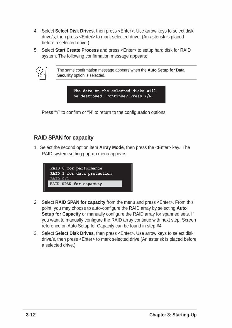
3-12 Chapter 3: Starting-Up
4. Select Select Disk Drives, then press <Enter>. Use arrow keys to select diskdrive/s, then press <Enter> to mark selected drive. (An asterisk is placedbefore a selected drive.)
5. Select Start Create Process and press <Enter> to setup hard disk for RAIDsystem. The following confirmation message appears:
Press “Y” to confirm or “N” to return to the configuration options.
The data on the selected disks will be destroyed. Continue? Press Y/N
RAID SPAN for capacity
1. Select the second option item Array Mode, then press the <Enter> key. TheRAID system setting pop-up menu appears.
RAID 0 for performance RAID 1 for data protection RAID 0/1 RAID SPAN for capacityRAID SPAN for capacity
2. Select RAID SPAN for capacity from the menu and press <Enter>. From thispoint, you may choose to auto-configure the RAID array by selecting AutoSetup for Capacity or manually configure the RAID array for spanned sets. Ifyou want to manually configure the RAID array continue with next step. Screenreference on Auto Setup for Capacity can be found in step #4
3. Select Select Disk Drives, then press <Enter>. Use arrow keys to select diskdrive/s, then press <Enter> to mark selected drive.(An asterisk is placed beforea selected drive.)
The same confirmation message appears when the Auto Setup for DataSecurity option is selected.

ASUS A7V600-X Motherboard 3-13
3.4.5 Select Boot Array1. In the VIA RAID BIOS utility main menu, select Select Boot Array then press
the <Enter> key. The focus is directed to the list of channel used for IDE RAIDarrays.
2. Press the <Enter> key to select a RAID array for boot. The Status of theselected array will change to Boot. Press <ESC> key to go return to menuitems. Follow the same procedure to deselect the the boot array.
3.4.4 Delete Array1. In the VIA RAID BIOS utility main menu, select Delete Array then press the
<Enter> key. The focus is directed to the list of channel used for IDE RAIDarrays.
2. Press the <Enter> key to select a RAID array to delete. The followingconfirmation message appears.
Press “Y” to confirm or “N” to return to the configuration options.
The selected array will be destroyed.Are you sure? Continue? Press Y/N
4. Select Start Create Process and press <Enter> to setup hard disk for RAIDsystem. The following confirmation message appears:
Press “Y” to confirm or “N” to return to the configuration options.
The data on the selected disks will be destroyed. Continue? Press Y/N
Channel��� Drive Name�� Array Name�� Mode� Size(GB) Status
[ ]Channel0 Master� XXXXXXXXXX���� xxxxxxx xxx.xx� Hdd[ ]Channel0 Slave� XXXXXXXXXX���� xxxxxxx xxx.xx� Hdd Channel1 Master� No Drive Channel1 Slave � No Drive
ESC� : Exit
The same confirmation message appears when the Auto Setup for Capacityoption is selected.
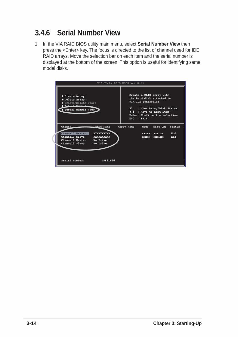
3-14 Chapter 3: Starting-Up
3.4.6 Serial Number View1. In the VIA RAID BIOS utility main menu, select Serial Number View then
press the <Enter> key. The focus is directed to the list of channel used for IDERAID arrays. Move the selection bar on each item and the serial number isdisplayed at the bottom of the screen. This option is useful for identifying samemodel disks.
Channel��� Drive Name� Array Name� Mode� Size(GB) Status
Channel0 Master� XXXXXXXXXX���� xxxxx xxx.xx� HddChannel0 Slave�� XXXXXXXXXX���� xxxxx xxx.xx� HddChannel1 Master� No DriveChannel1 Slave � No Drive
VIA Tech. RAID BIOS Ver 0.96
Create Array Delete Array Create/Delete Spare Select Boot Array Serial Number View
Create a RAID array withthe hard disk attached toVIA IDE controller
F1� : View Array/Disk Status , � : Move to next itemEnter: Confirme the selectionESC� : Exit
Serial Number:��� VJF41646