a6260 a6270 fuel injector cleaning with inspection or
TRANSCRIPT
Emissions Recall
Page 1 of 20 Vendor Ref: RCB-010-08
Subject: Fuel Injector Inspection Date: 03-03-2009 Bulletin: R0034 Campaign #: A6260_A6270 Affected Models: 2008-2009 NA6J (145), NB6J (165), NC6J (185), ND8J (238), NE8J (268), NJ8J (268A), NV8J (338)
NOTE: When scheduling a vehicle for this Emission Recall, instruct the customer to completely fill the fuel tank(s) prior to delivery to the Dealer. No claims for fuel will be accepted as part of this Recall.
Description: This bulletin includes the instructions to complete the following.
1. Determine the condition of the fuel injectors by monitoring quantity value using Hino Diagnostic Explorer.
2. If the fuel injector condition is determined to be “Acceptable” Diesel Cleaner will be added to the fuel without replacing the fuel injectors.
3. If the fuel injector condition is determined to be “Unacceptable” the fuel injectors will be replaced without adding the Diesel Cleaner.
Subject Vehicles:
2008 and 2009 model year NA6J (145), NB6J (165), NC6J (185), ND8J (238), NE8J (268), NJ8J (268A), and NV8J (338) Hino conventional trucks assembled at the Long Beach, CA. and Williamstown, WV assembly plants.
Condition: Abnormal noise and vibration within the engine occurs due to the impeded operation of the injector needle which is caused by the formation of deposits in the fuel. The deposit formation occurs when metallic compounds, which are a part of the synthetic rubber hose material, are extracted from the synthetic rubber by naturally occurring solvents in the fuel and then exposed to abnormally high fuel temperature. The abnormally high fuel temperature is created when excessive air enters the fuel stream from the fuel filter and is compressed by the supply pump. This deposit accumulates on the fuel injector needle and impedes the needle movement which causes abnormal post injection timing to occur. The abnormal post injection timing causes the abnormal noise and vibration of the engine.
Emissions Recall
Page 2 of 20 Vendor Ref: RCB-010-08
Important: Verify on the Hino DCS Warranty System that the vehicle still needs to have this work performed. Before You Begin: Read and understand all instructions and procedures before you begin. Read and observe all Caution and Warning safety alerts that precede these instructions while following these procedures. The alerts help to avoid damage to components, serious personal injury, or both. Park the vehicle on a flat and level surface. Apply the parking brake and confirm parking brake activation. Shift transmission to NEUTRAL. Block the wheels to prevent the vehicle from moving. Use care when working around surfaces which may be hot. Wear safety glasses to prevent eye injuries. Properly calibrated torque wrenches must be used to prevent possible ensuing damage. Refer to any applicable Material Safety Data Sheet (M.S.D.S.) for additional information.
!!! WARNING !!!
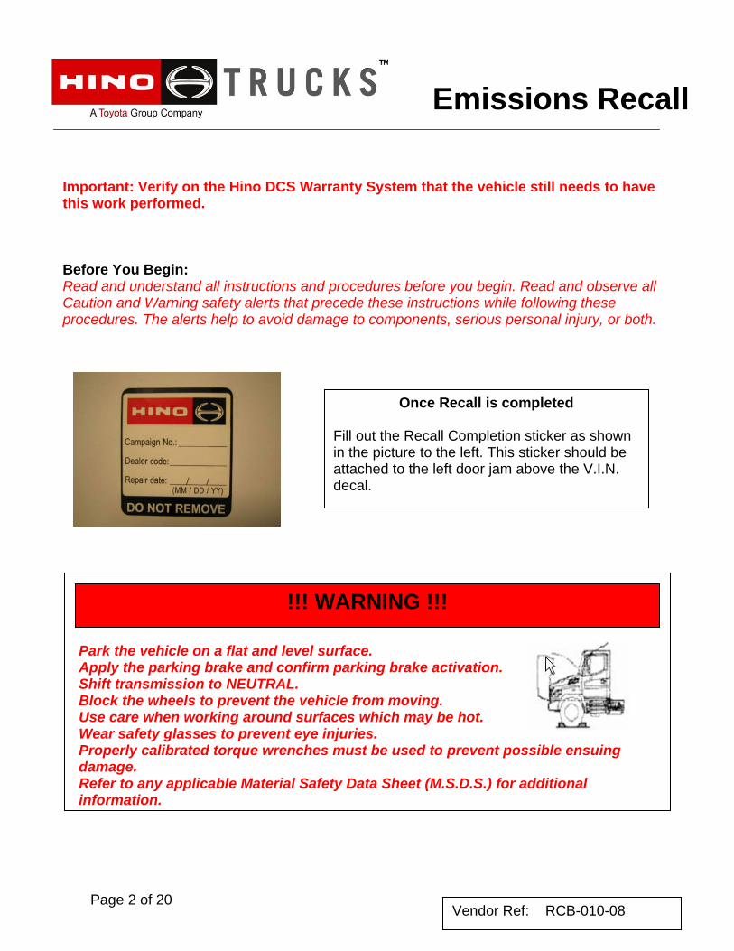
Once Recall is completed
Fill out the Recall Completion sticker as shown in the picture to the left. This sticker should be attached to the left door jam above the V.I.N. decal.
Emissions Recall
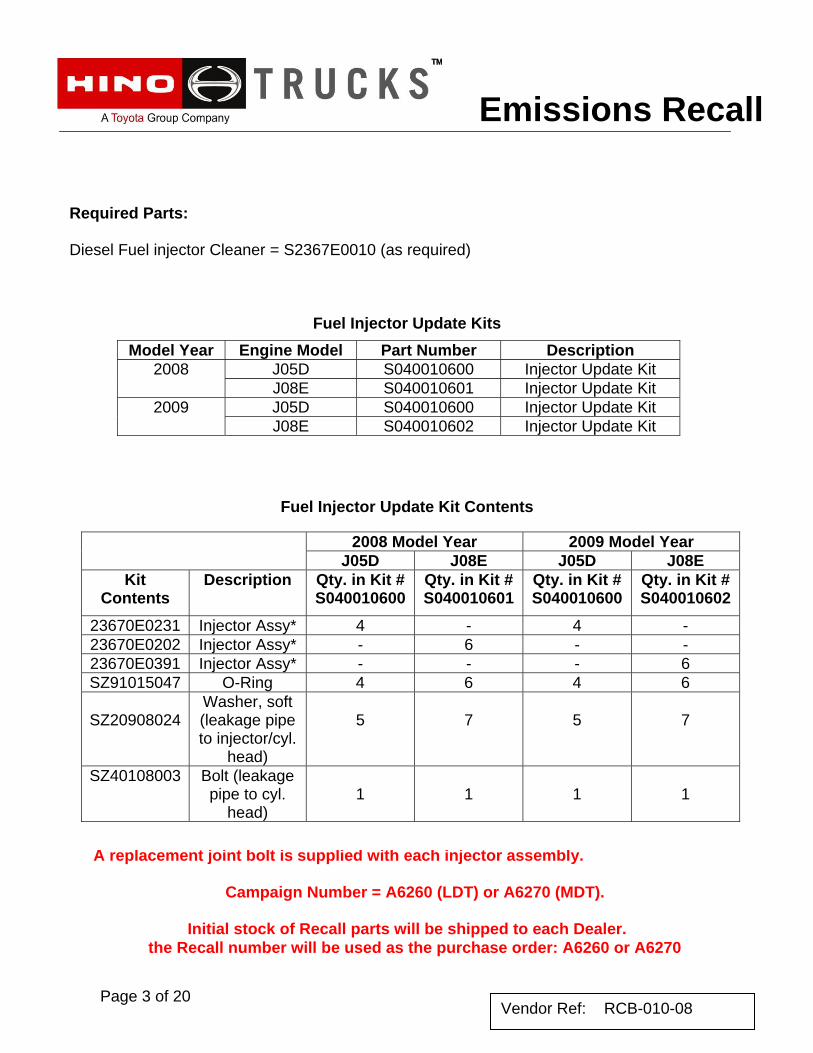
Required Parts: Diesel Fuel injector Cleaner = S2367E0010 (as required)
Fuel Injector Update Kits
Fuel Injector Update Kit Contents
A replacement joint bolt is supplied with each injector assembly.
Campaign Number = A6260 (LDT) or A6270 (MDT).
Initial stock of Recall parts will be shipped to each Dealer. the Recall number will be used as the purchase order: A6260 or A6270
Model Year Engine Model Part Number Description J05D S040010600 Injector Update Kit 2008 J08E S040010601 Injector Update Kit J05D S040010600 Injector Update Kit 2009 J08E S040010602 Injector Update Kit
2008 Model Year 2009 Model Year J05D J08E J05D J08E
Kit Contents
Description Qty. in Kit # S040010600
Qty. in Kit # S040010601
Qty. in Kit # S040010600
Qty. in Kit # S040010602
23670E0231 Injector Assy* 4 - 4 - 23670E0202 Injector Assy* - 6 - - 23670E0391 Injector Assy* - - - 6 SZ91015047 O-Ring 4 6 4 6
SZ20908024
Washer, soft (leakage pipe to injector/cyl.
head)
5
7
5
7
SZ40108003 Bolt (leakage pipe to cyl.
head)
1
1
1
1
Page 3 of 20 Vendor Ref: RCB-010-08
Emissions Recall
Page 4 of 20 Vendor Ref: RCB-010-08
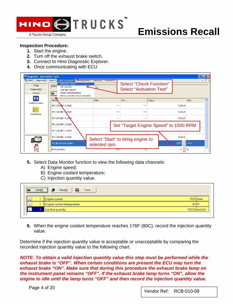
Inspection Procedure: 1. Start the engine. 2. Turn off the exhaust brake switch. 3. Connect to Hino Diagnostic Explorer. 4. Once communicating with ECU
5. Select Data Monitor function to view the following data channels:
A) Engine speed; B) Engine coolant temperature; C) Injection quantity value.
6. When the engine coolant temperature reaches 176F (80C), record the injection quantity
value.
Determine if the injection quantity value is acceptable or unacceptable by comparing the recorded injection quantity value to the following chart. NOTE: To obtain a valid injection quantity value this step must be performed while the exhaust brake is “OFF”. When certain conditions are present the ECU may turn the exhaust brake “ON”. Make sure that during this procedure the exhaust brake lamp on the instrument panel remains “OFF”. If the exhaust brake lamp turns “ON”, allow the engine to idle until the lamp turns “OFF” and then record the injection quantity value.
Select “Check Function” Select “Activation Test”
Set “Target Engine Speed” to 1500 RPM
Select “Start” to bring engine to selected rpm.
Emissions Recall
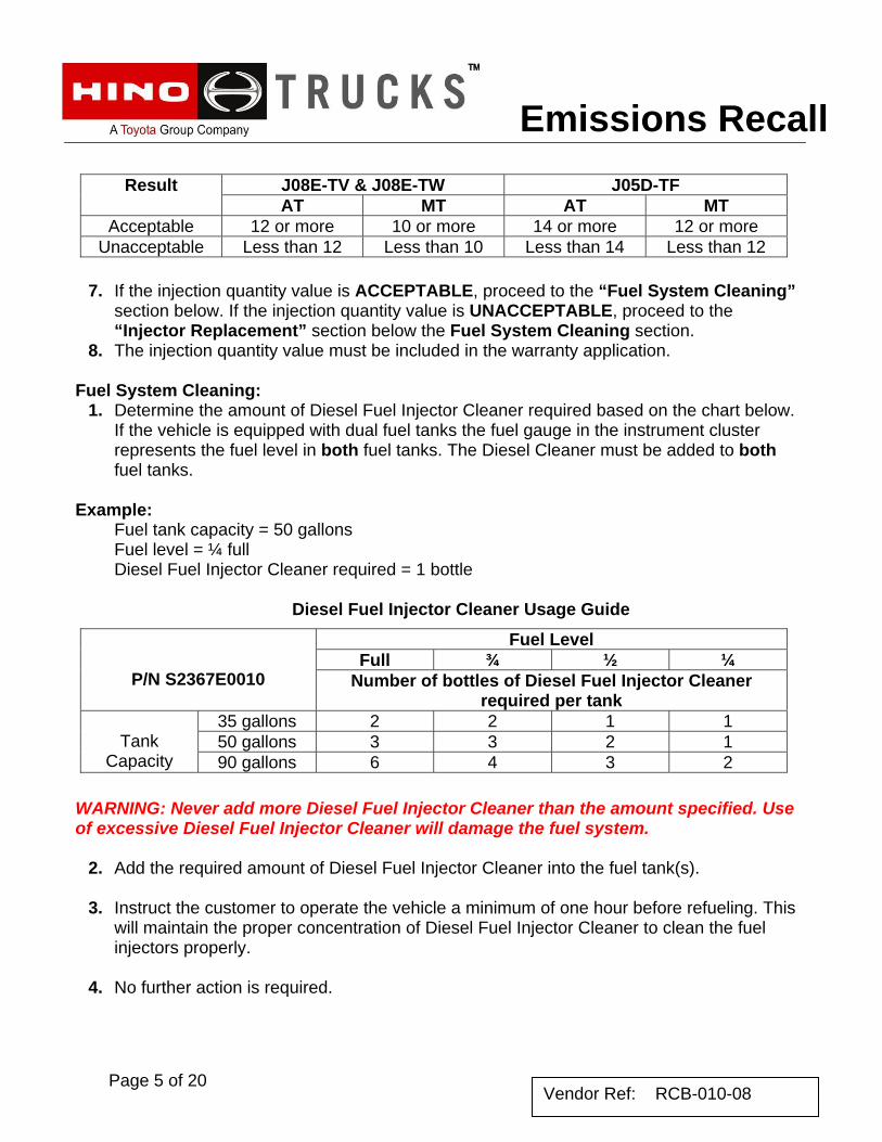
7. If the injection quantity value is ACCEPTABLE, proceed to the “Fuel System Cleaning” section below. If the injection quantity value is UNACCEPTABLE, proceed to the “Injector Replacement” section below the Fuel System Cleaning section.
8. The injection quantity value must be included in the warranty application. Fuel System Cleaning:
1. Determine the amount of Diesel Fuel Injector Cleaner required based on the chart below. If the vehicle is equipped with dual fuel tanks the fuel gauge in the instrument cluster represents the fuel level in both fuel tanks. The Diesel Cleaner must be added to both fuel tanks.
Example: Fuel tank capacity = 50 gallons Fuel level = ¼ full Diesel Fuel Injector Cleaner required = 1 bottle
Diesel Fuel Injector Cleaner Usage Guide
WARNING: Never add more Diesel Fuel Injector Cleaner than the amount specified. Use of excessive Diesel Fuel Injector Cleaner will damage the fuel system.
2. Add the required amount of Diesel Fuel Injector Cleaner into the fuel tank(s).
3. Instruct the customer to operate the vehicle a minimum of one hour before refueling. This will maintain the proper concentration of Diesel Fuel Injector Cleaner to clean the fuel injectors properly.
4. No further action is required.
J08E-TV & J08E-TW J05D-TF Result AT MT AT MT
Acceptable 12 or more 10 or more 14 or more 12 or more Unacceptable Less than 12 Less than 10 Less than 14 Less than 12
Fuel Level Full ¾ ½ ¼
P/N S2367E0010 Number of bottles of Diesel Fuel Injector Cleaner required per tank
35 gallons 2 2 1 1 50 gallons 3 3 2 1
Tank
Capacity 90 gallons 6 4 3 2
Page 5 of 20 Vendor Ref: RCB-010-08
Emissions Recall
Page 6 of 20 Vendor Ref: RCB-010-08
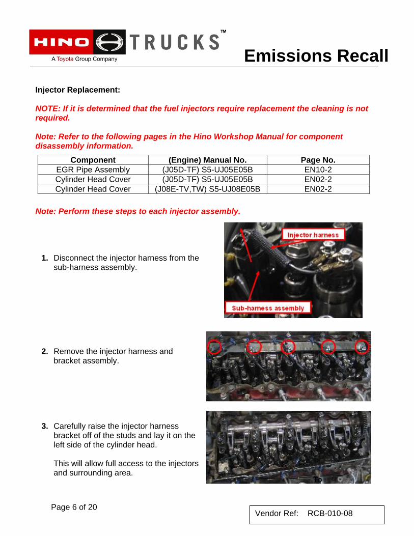
Injector Replacement: NOTE: If it is determined that the fuel injectors require replacement the cleaning is not required. Note: Refer to the following pages in the Hino Workshop Manual for component disassembly information. Note: Perform these steps to each injector assembly.
1. Disconnect the injector harness from the sub-harness assembly.
2. Remove the injector harness and
bracket assembly.
3. Carefully raise the injector harness bracket off of the studs and lay it on the left side of the cylinder head. This will allow full access to the injectors and surrounding area.
Component (Engine) Manual No. Page No. EGR Pipe Assembly (J05D-TF) S5-UJ05E05B EN10-2 Cylinder Head Cover (J05D-TF) S5-UJ05E05B EN02-2 Cylinder Head Cover (J08E-TV,TW) S5-UJ08E05B EN02-2
Emissions Recall
Page 7 of 20 Vendor Ref: RCB-010-08
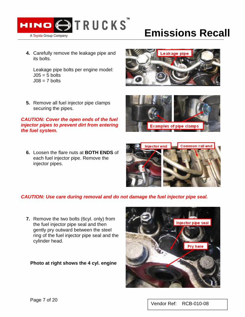
4. Carefully remove the leakage pipe and
its bolts. Leakage pipe bolts per engine model: J05 = 5 bolts J08 = 7 bolts
5. Remove all fuel injector pipe clamps
securing the pipes.
CAUTION: Cover the open ends of the fuel injector pipes to prevent dirt from entering the fuel system.
6. Loosen the flare nuts at BOTH ENDS of each fuel injector pipe. Remove the injector pipes.
CAUTION: Use care during removal and do not damage the fuel injector pipe seal.
7. Remove the two bolts (6cyl. only) from the fuel injector pipe seal and then gently pry outward between the steel ring of the fuel injector pipe seal and the cylinder head.
Photo at right shows the 4 cyl. engine

Emissions Recall
Page 8 of 20 Vendor Ref: RCB-010-08
8. Remove the injector hold down clamp bolts.
9. Remove each fuel injector from the cylinder head.
CAUTION: The seal between the fuel injector and the nozzle seat will be damaged if deposits are not removed prior to injector installation.
10. Inspect the nozzle seat for carbon deposits.
Remove any deposits with parts cleaner and a brass brush. Once clean, the nozzle seat will appear copper in color.
Emissions Recall
Page 9 of 20 Vendor Ref: RCB-010-08
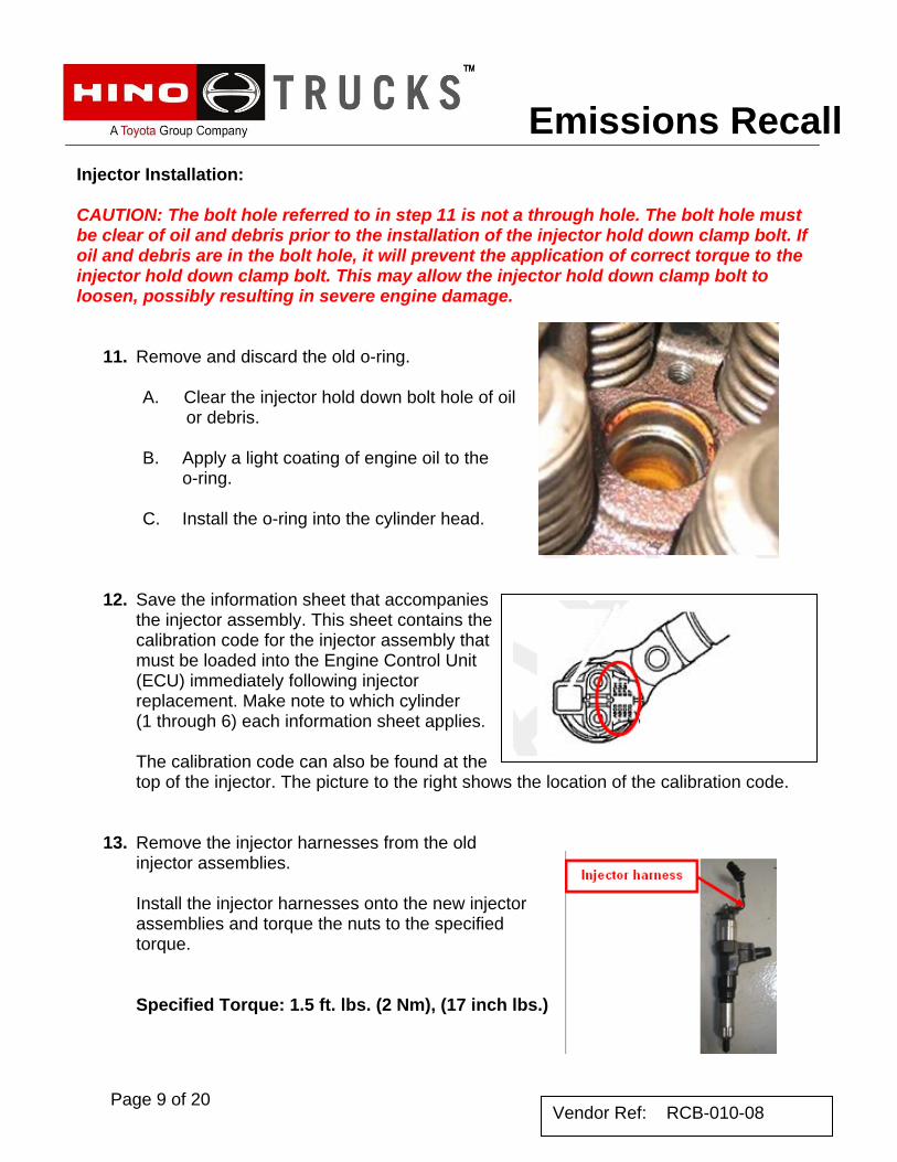
Injector Installation: CAUTION: The bolt hole referred to in step 11 is not a through hole. The bolt hole must be clear of oil and debris prior to the installation of the injector hold down clamp bolt. If oil and debris are in the bolt hole, it will prevent the application of correct torque to the injector hold down clamp bolt. This may allow the injector hold down clamp bolt to loosen, possibly resulting in severe engine damage.
11. Remove and discard the old o-ring.
A. Clear the injector hold down bolt hole of oil or debris.
B. Apply a light coating of engine oil to the
o-ring. C. Install the o-ring into the cylinder head.
12. Save the information sheet that accompanies
the injector assembly. This sheet contains the calibration code for the injector assembly that must be loaded into the Engine Control Unit (ECU) immediately following injector replacement. Make note to which cylinder (1 through 6) each information sheet applies. The calibration code can also be found at the top of the injector. The picture to the right shows the location of the calibration code.
13. Remove the injector harnesses from the old injector assemblies. Install the injector harnesses onto the new injector assemblies and torque the nuts to the specified torque. Specified Torque: 1.5 ft. lbs. (2 Nm), (17 inch lbs.)
Emissions Recall
Page 10 of 20 Vendor Ref: RCB-010-08
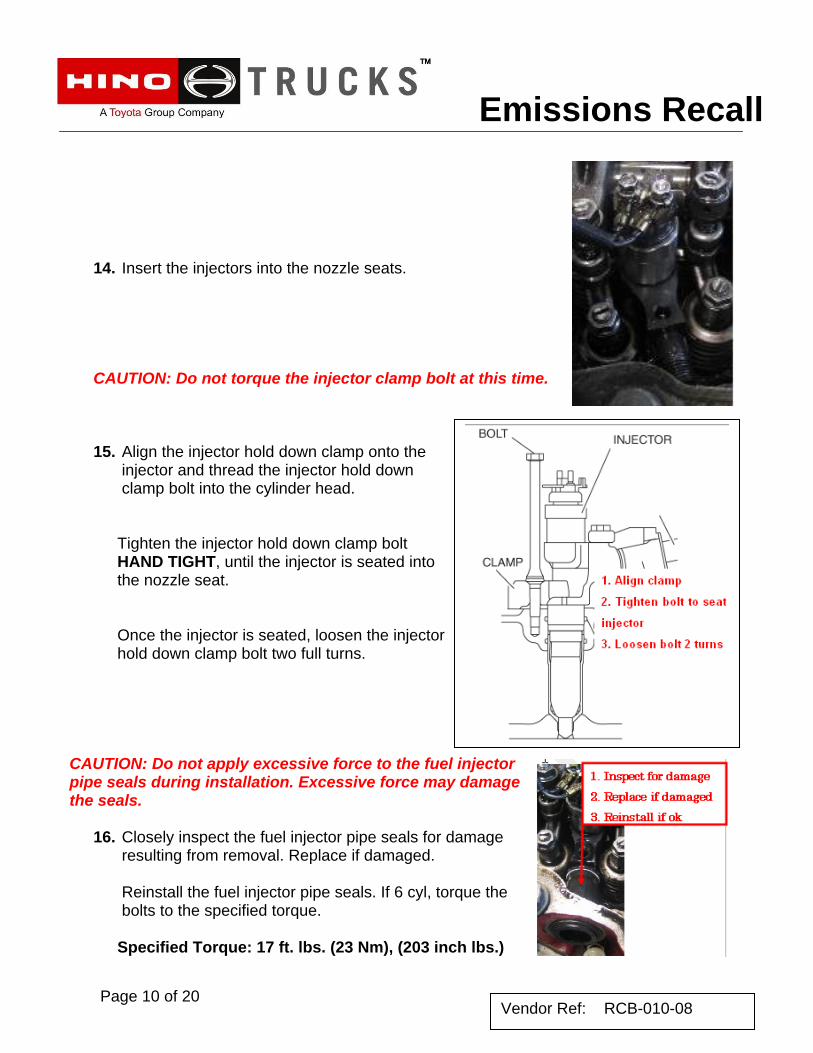
14. Insert the injectors into the nozzle seats.
CAUTION: Do not torque the injector clamp bolt at this time. 15. Align the injector hold down clamp onto the
injector and thread the injector hold down clamp bolt into the cylinder head. Tighten the injector hold down clamp bolt HAND TIGHT, until the injector is seated into the nozzle seat. Once the injector is seated, loosen the injector hold down clamp bolt two full turns.
CAUTION: Do not apply excessive force to the fuel injector pipe seals during installation. Excessive force may damage the seals.
16. Closely inspect the fuel injector pipe seals for damage resulting from removal. Replace if damaged. Reinstall the fuel injector pipe seals. If 6 cyl, torque the bolts to the specified torque. Specified Torque: 17 ft. lbs. (23 Nm), (203 inch lbs.)
Emissions Recall
Page 11 of 20 Vendor Ref: RCB-010-08
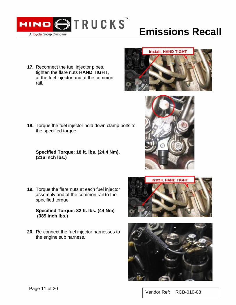
17. Reconnect the fuel injector pipes. tighten the flare nuts HAND TIGHT, at the fuel injector and at the common rail.
18. Torque the fuel injector hold down clamp bolts to the specified torque. Specified Torque: 18 ft. lbs. (24.4 Nm), (216 inch lbs.)
19. Torque the flare nuts at each fuel injector assembly and at the common rail to the specified torque. Specified Torque: 32 ft. lbs. (44 Nm) (389 inch lbs.)
20. Re-connect the fuel injector harnesses to the engine sub harness.
Emissions Recall
Page 12 of 20 Vendor Ref: RCB-010-08
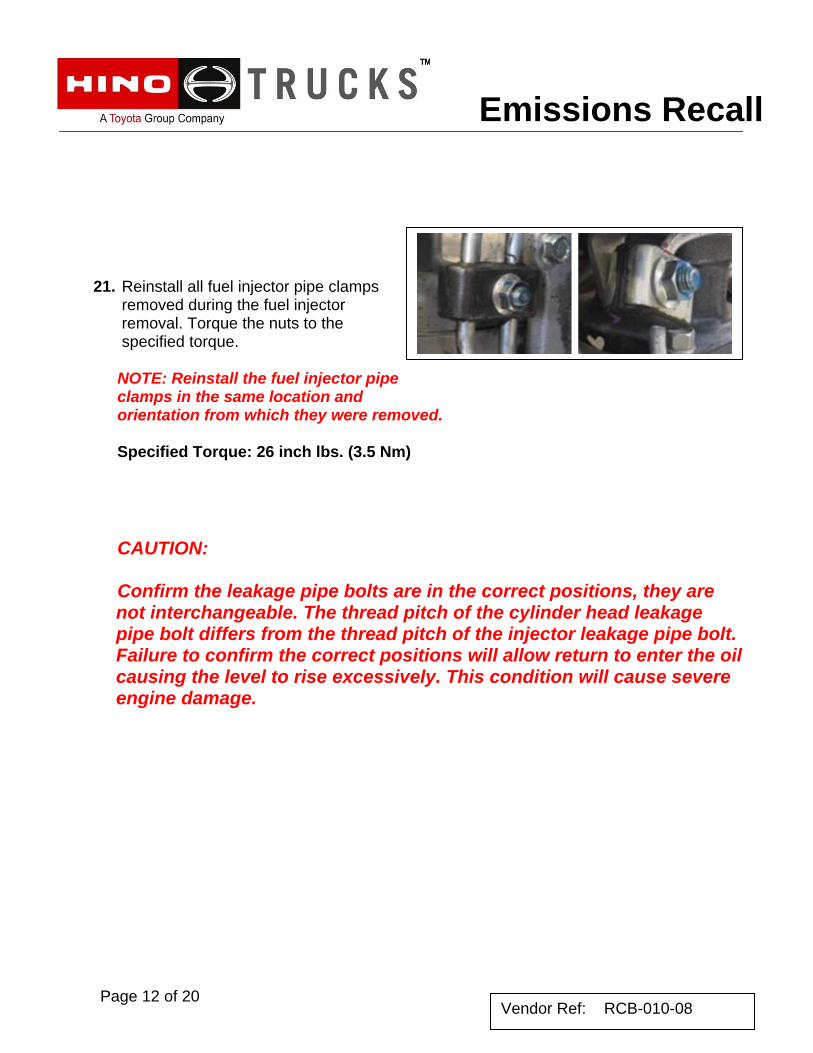
21. Reinstall all fuel injector pipe clamps removed during the fuel injector removal. Torque the nuts to the specified torque. NOTE: Reinstall the fuel injector pipe clamps in the same location and orientation from which they were removed. Specified Torque: 26 inch lbs. (3.5 Nm) CAUTION:
Confirm the leakage pipe bolts are in the correct positions, they are not interchangeable. The thread pitch of the cylinder head leakage pipe bolt differs from the thread pitch of the injector leakage pipe bolt. Failure to confirm the correct positions will allow return to enter the oil causing the level to rise excessively. This condition will cause severe engine damage.
Emissions Recall
Page 13 of 20 Vendor Ref: RCB-010-08
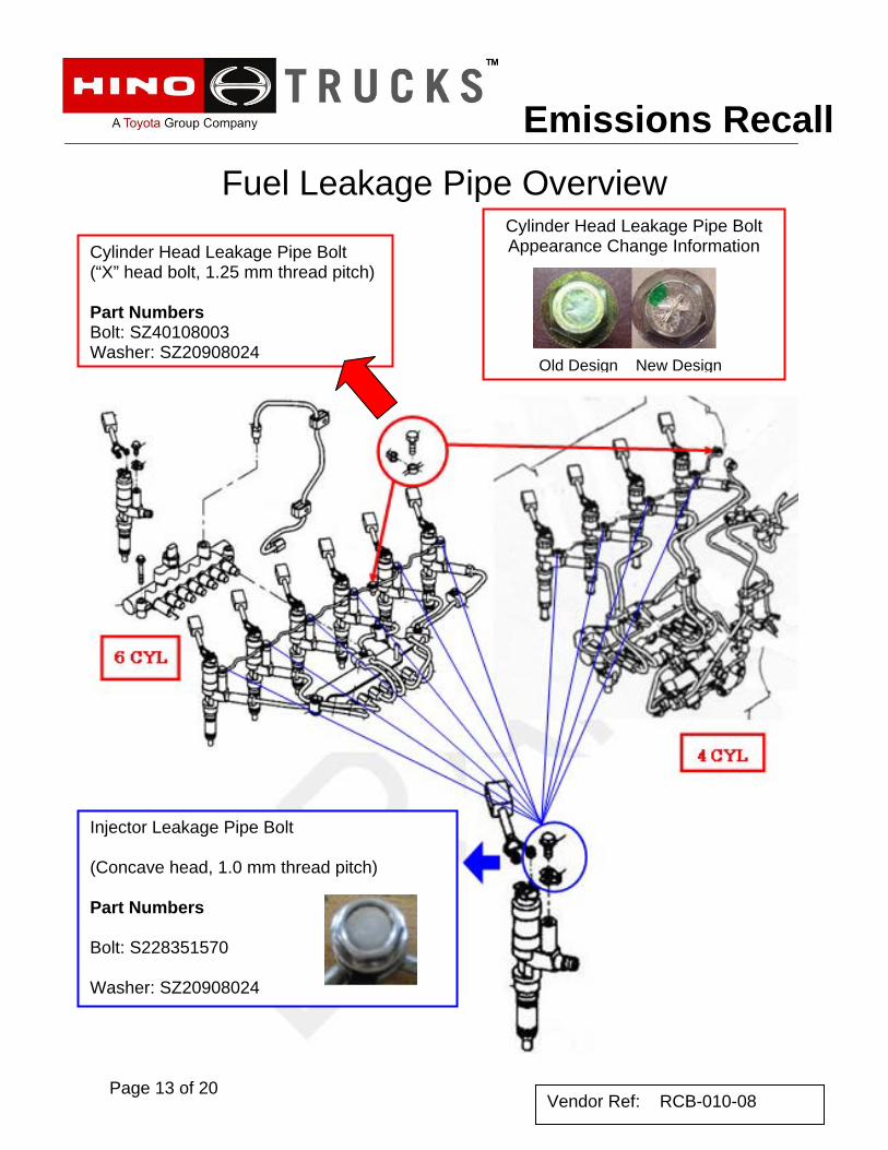
Fuel Leakage Pipe Overview
Cylinder Head Leakage Pipe Bolt (“X” head bolt, 1.25 mm thread pitch) Part Numbers Bolt: SZ40108003 Washer: SZ20908024
Cylinder Head Leakage Pipe Bolt Appearance Change Information
Old Design New Design
Injector Leakage Pipe Bolt (Concave head, 1.0 mm thread pitch) Part Numbers Bolt: S228351570 Washer: SZ20908024
Emissions Recall
Page 14 of 20 Vendor Ref: RCB-010-08
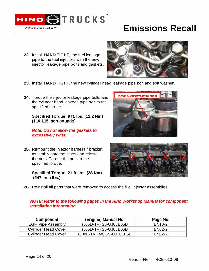
22. Install HAND TIGHT, the fuel leakage
pipe to the fuel injectors with the new injector leakage pipe bolts and gaskets.
23. Install HAND TIGHT, the new cylinder head leakage pipe bolt and soft washer. 24. Torque the injector leakage pipe bolts and
the cylinder head leakage pipe bolt to the specified torque. Specified Torque: 9 ft. lbs. (12.2 Nm)(110-115 inch-pounds) Note: Do not allow the gaskets to excessively twist.
25. Remount the injector harness / bracket assembly onto the studs and reinstall the nuts. Torque the nuts to the specified torque. Specified Torque: 21 ft. lbs. (28 Nm) (247 inch lbs.)
26. Reinstall all parts that were removed to access the fuel injector assemblies.
NOTE: Refer to the following pages in the Hino Workshop Manual for component installation information.
Component (Engine) Manual No. Page No. EGR Pipe Assembly (J05D-TF) S5-UJ05E05B EN10-2 Cylinder Head Cover (J05D-TF) S5-UJ05E05B EN02-2 Cylinder Head Cover (J08E-TV,TW) S5-UJ08E05B EN02-2
Emissions Recall
Page 15 of 20 Vendor Ref: RCB–010-08
New Injector Calibration Codes:
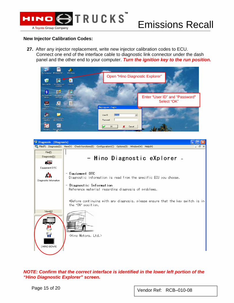
27. After any injector replacement, write new injector calibration codes to ECU. Connect one end of the interface cable to diagnostic link connector under the dash panel and the other end to your computer. Turn the ignition key to the run position.
NOTE: Confirm that the correct interface is identified in the lower left portion of the “Hino Diagnostic Explorer” screen.
Open “Hino Diagnostic Explorer”
Enter “User ID” and “Password” Select “OK”
Emissions Recall
Page 16 of 20 Vendor Ref: RCB–010-08
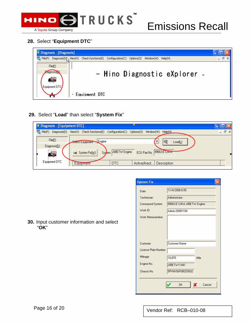
28. Select “Equipment DTC”
29. Select “Load” than select “System Fix”
30. Input customer information and select
“OK”
Emissions Recall
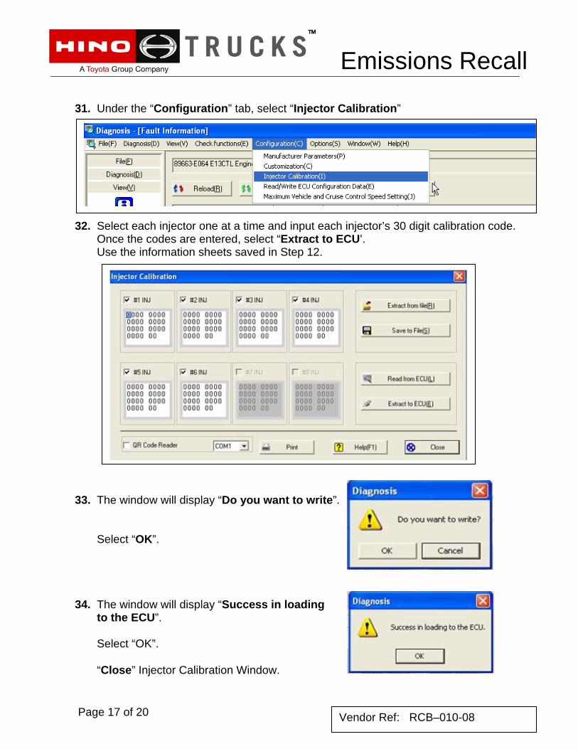
31. Under the “Configuration” tab, select “Injector Calibration”
32. Select each injector one at a time and input each injector’s 30 digit calibration code.
Once the codes are entered, select “Extract to ECU’. Use the information sheets saved in Step 12.
33. The window will display “Do you want to write”. Select “OK”.
34. The window will display “Success in loading to the ECU”. Select “OK”. “Close” Injector Calibration Window.
Page 17 of 20 Vendor Ref: RCB–010-08
Emissions Recall
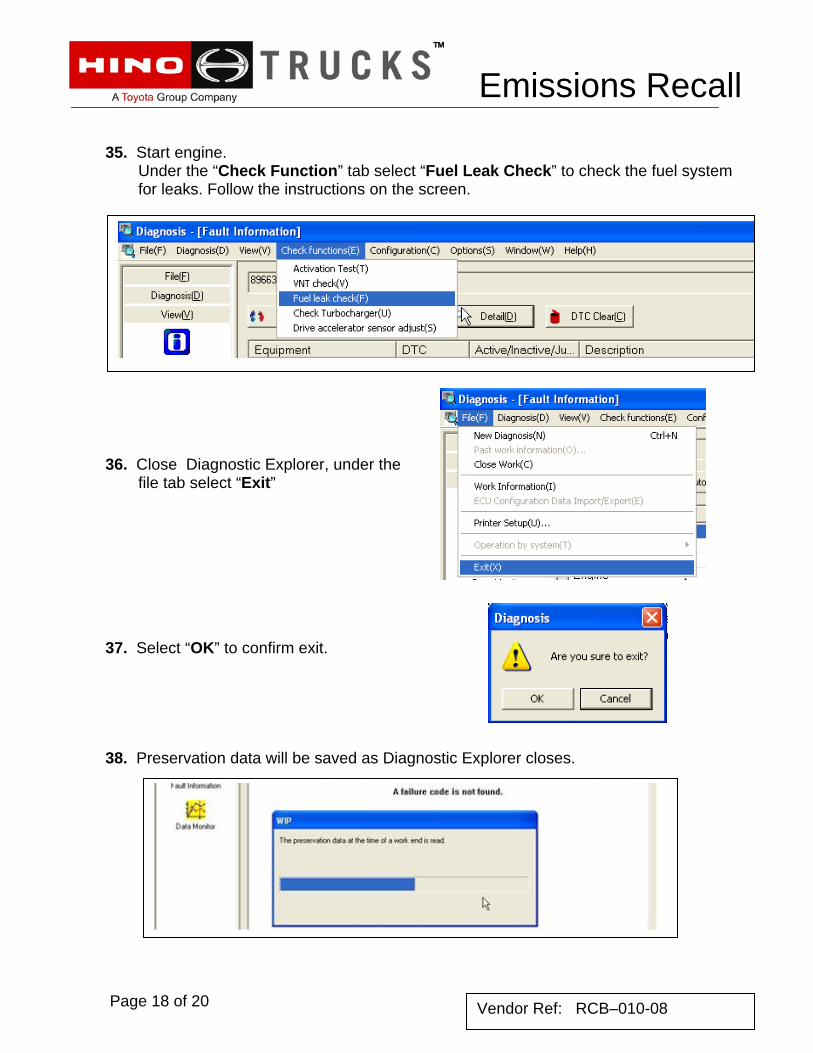
35. Start engine.
Under the “Check Function” tab select “Fuel Leak Check” to check the fuel system for leaks. Follow the instructions on the screen.
36. Close Diagnostic Explorer, under the file tab select “Exit” 37. Select “OK” to confirm exit.
38. Preservation data will be saved as Diagnostic Explorer closes.
Page 18 of 20 Vendor Ref: RCB–010-08
Emissions Recall
Page 19 of 20 Vendor Ref: RCB–010-08
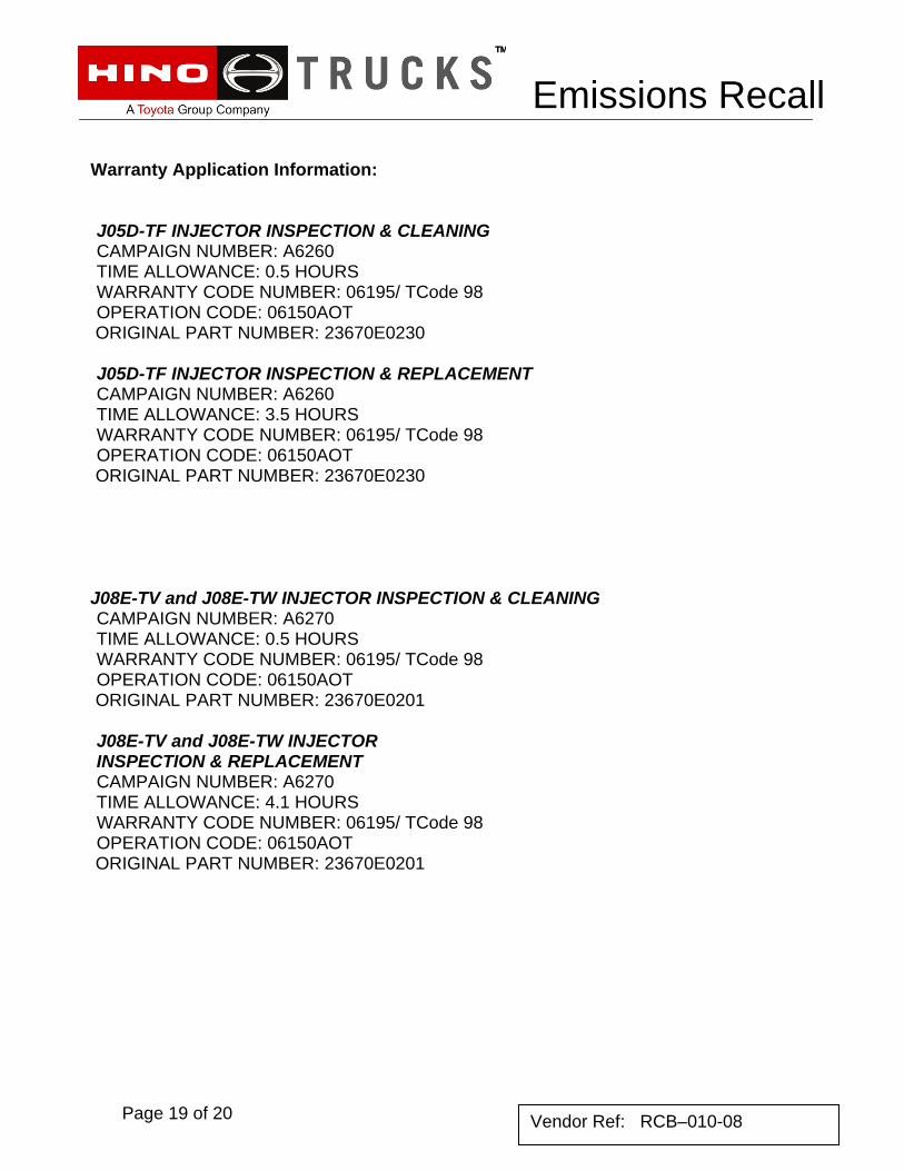
Warranty Application Information: J05D-TF INJECTOR INSPECTION & CLEANING CAMPAIGN NUMBER: A6260 TIME ALLOWANCE: 0.5 HOURS WARRANTY CODE NUMBER: 06195/ TCode 98 OPERATION CODE: 06150AOT
ORIGINAL PART NUMBER: 23670E0230 J05D-TF INJECTOR INSPECTION & REPLACEMENT CAMPAIGN NUMBER: A6260 TIME ALLOWANCE: 3.5 HOURS WARRANTY CODE NUMBER: 06195/ TCode 98 OPERATION CODE: 06150AOT
ORIGINAL PART NUMBER: 23670E0230 J08E-TV and J08E-TW INJECTOR INSPECTION & CLEANING CAMPAIGN NUMBER: A6270 TIME ALLOWANCE: 0.5 HOURS WARRANTY CODE NUMBER: 06195/ TCode 98 OPERATION CODE: 06150AOT
ORIGINAL PART NUMBER: 23670E0201 J08E-TV and J08E-TW INJECTOR INSPECTION & REPLACEMENT CAMPAIGN NUMBER: A6270 TIME ALLOWANCE: 4.1 HOURS WARRANTY CODE NUMBER: 06195/ TCode 98 OPERATION CODE: 06150AOT
ORIGINAL PART NUMBER: 23670E0201
Page 20 of 20
Emissions Recall
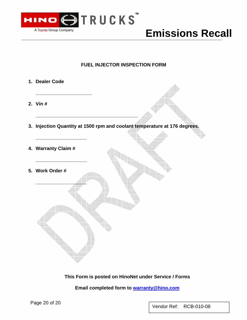
FUEL INJECTOR INSPECTION FORM
1. Dealer Code
_____________________ 2. Vin #
______________________________________
3. Injection Quantity at 1500 rpm and coolant temperature at 176 degrees.
___________________
4. Warranty Claim #
___________________
5. Work Order #
___________________
This Form is posted on HinoNet under Service / Forms
Email completed form to [email protected]
Vendor Ref: RCB-010-08