a white paper from ansys, inc. white paper primer on using... · mesh that resolves the boundary...
TRANSCRIPT
IINTRODUCTIONYou are an engineering manager or analyst, and your task is to solve several problems involving the aerodynamics of a
UAS (unmanned air system). Your experience with CFD (computational fluid dynamics) is limited, and your company’s
UAV (unmanned aerial vehicle) project is on a tight schedule. The purpose of this white paper is to introduce you to the
types of aerodynamic problems that are typically solved using CFD software to help guide your decision process. The
paper consists of a series of case studies, each of which includes the motivation for applying fluids engineering to that
particular problem.
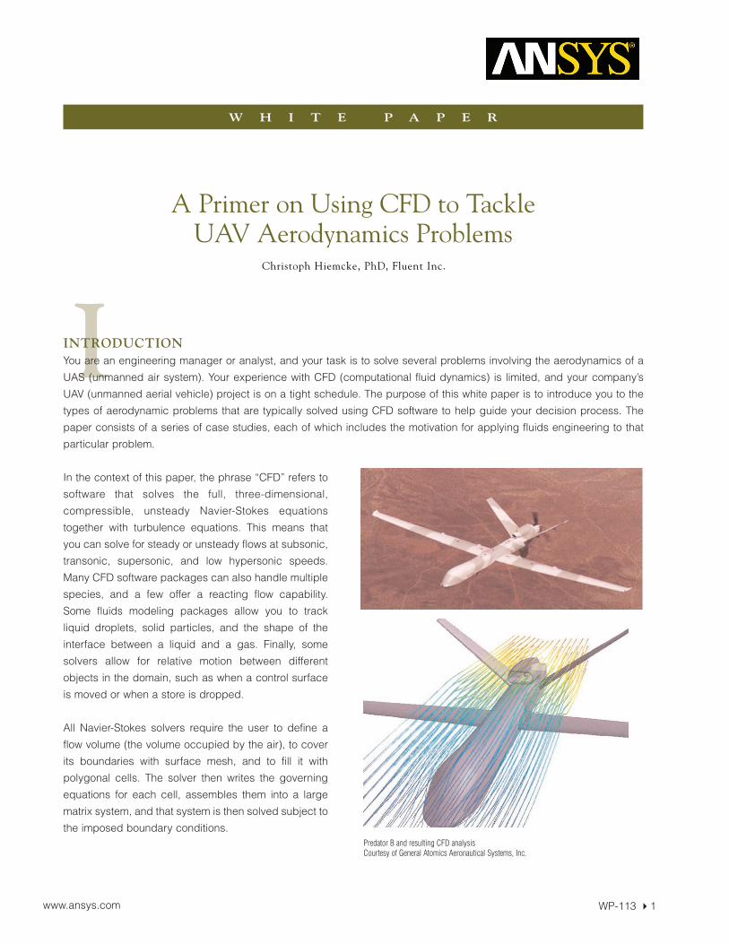
In the context of this paper, the phrase “CFD” refers to
software that solves the full, three-dimensional,
compressible, unsteady Navier-Stokes equations
together with turbulence equations. This means that
you can solve for steady or unsteady flows at subsonic,
transonic, supersonic, and low hypersonic speeds.
Many CFD software packages can also handle multiple
species, and a few offer a reacting flow capability.
Some fluids modeling packages allow you to track
liquid droplets, solid particles, and the shape of the
interface between a liquid and a gas. Finally, some
solvers allow for relative motion between different
objects in the domain, such as when a control surface
is moved or when a store is dropped.
All Navier-Stokes solvers require the user to define a
flow volume (the volume occupied by the air), to cover
its boundaries with surface mesh, and to fill it with
polygonal cells. The solver then writes the governing
equations for each cell, assembles them into a large
matrix system, and that system is then solved subject to
the imposed boundary conditions.
A Primer on Using CFD to TackleUAV Aerodynamics Problems
A W H I T E P A P E R F R O M A N S Y S , I N C .
WP-113 �1
W H I T E P A P E R
www.ansys.com
Christoph Hiemcke, PhD, Fluent Inc.
Predator B and resulting CFD analysisCourtesy of General Atomics Aeronautical Systems, Inc.

Part one of the paper focuses on the aerodynamics of the entire aircraft and includes three case studies. Part two con-
sists of four case studies that involve a subsystem of a UAV.
PART 1: OVERALL VEHICLE AERODYNAMICSCCaassee SSttuuddyy 11aa:: PPrreeddiiccttiinngg AAeerrooddyynnaammiicc FFoorrcceess oonn aa UUAAVV DDuurriinngg EExxttrreemmee MMaanneeuuvveerrss
Since UAVs are not subject to the limitations on the number of g’s that a human pilot would impose, they can perform
very drastic maneuvers. Such maneuvers often involve stalls or near-stalls, with significant regions of separated flow.
Flight tests in these conditions will put the vehicle at great risk, and wind tunnel tests are very costly and may suffer from
scaling effects. More traditional analysis tools, such as panel methods or vortex lattice methods, cannot tolerate these
flow conditions due to the extensive flow separation.
It is worthwhile to note that a good prediction of the aerodynamic
forces and moments during subsonic, transonic, and very low
supersonic flight (below Mach 1.3 or so) requires the user to create a
mesh that resolves the boundary layers with either hexahedral cells or
triangular prisms (wedge cells). At speeds above that, the aerody-
namic forces will be dominated by the shocks; for example, the drag
will be dominated by wave drag. If large areas of separated flow are
a concern, then a boundary layer mesh is still mandatory even at high
speeds.
CCaassee SSttuuddyy 11bb:: PPrreeddiiccttiinngg AAeerrooddyynnaammiicc FFoorrcceess oonn aa MMoorrpphhiinngg UUAAVV iinn TTrraannssoonniicc FFlliigghhtt
A morphing UAV is one which changes its shape during flight. Morphing UAVs, such as Boeing’s “Dominator,” morph
right after they are launched: first the wings are folded out from under the body using a sideward rotation, and then they
are extended via a telescoping motion. Other morphing UAVs are controlled through the use of memory alloys in their
wings - currents passed through those sections cause the wing to deform, thereby acting as ailerons and flaps. More
radical concepts involve a drastic change in the planform shape of the wings.
WP-113 � 2© 2008 ANSYS, Inc. All Rights Reserved.
Static pressure on a UAV
Vortex formation during the flapping cycle of a flyParticle tracks show the air movement caused by the flapping wings on a fly
All morphing UAVs change their shape as a function of time, so any computational model must also permit the shape
to vary with time, unless a series of steady-state analyses is sufficient. This is a case where dynamic mesh or deform-
ing mesh is recommended.
The fact that this UAV is also flying at transonic speed represents another challenge. For one, transonic flows are
governed by nonlinear partial differential equations. Furthermore, this flow will be unsteady since the aircraft is
morphing, and this means that the shock structures will interact with the boundary layers in an unsteady manner, so the
flow may well involve shock-induced separation. From a computational point of view, only Navier-Stokes CFD codes are
equipped to handle this type of flow.
It is often necessary to correctly predict both the location and strength of the shocks. Instead of beginning with a very
fine mesh from the start (which would be computationally expensive due to the high cell count), some CFD codes allow
you to adapt the mesh locally by splitting cells in those areas in which the gradients are the highest. By doing this, you
can resolve the shock nicely without using a prohibitively large mesh. When this approach is used for unsteady flows,
we speak of dynamic adaption.
CCaassee SSttuuddyy 11cc:: PPrreeddiiccttiinngg FFllooww AArroouunndd tthhee FFllaappppiinngg WWiinnggss oorr RRoottoorrss ooff aa MMiiccrroo--UUAAVV
Micro-UAVs (MUAVs) are designed to operate in small spaces, such as inside a building. For that reason, they must be
small, quiet, and able to hover. For these reasons, flapping wings or rotors are used to produce lift and thrust.
From the viewpoint of a fluid dynamicist, these flows are especially interesting because they are often transitional and
dominated by unsteady vortex dynamics. These facts also make them very challenging for analysis software packages.
In order to predict the flow around a flapping wing, the CFD package must be able to deform the shape of the wings
as a function of time. Just as in the case of the morphing UAV, a dynamic/deforming mesh capability is required.
Since the flow will be dominated by the evolution of vortex structures, it will be important to build a fine mesh to avoid
artificial dissipation of those vortices. Also, depending on the size and speed of the UAV, the flow may be transitional.
If transition from laminar to turbulent flow plays a significant role in the UAV’s performance, an LES (large eddy
simulation) turbulence model will likely be required.
If we are interested in rotorcraft MUAVs, we may be able to simplify the analysis. For example, if the focus is only the
overall interaction between the rotor and the fuselage, we may be able to model the rotor as an actuator disk by imple-
menting a blade element model. The same strategy can be used for tiltrotor designs or for analyzing UAVs with normal
propellers.
If a better fidelity of the flow around a tiltrotor or propeller is required (for example, to study the vehicle’s acoustics), we
can embed the tiltrotor or propeller in a puck-shaped volume and then physically rotate that puck within the overall
mesh. This capability is sometimes called a sliding mesh.
A high-fidelity simulation of the flow around a helicopter-like rotor is more complicated because the blade pitch varies
as a function of the azimuthal position of the blade. This means that we must use a dynamic/deforming mesh capability
to physically translate and rotate each blade during each new time step.
WP-113 � 3www.ansys.com
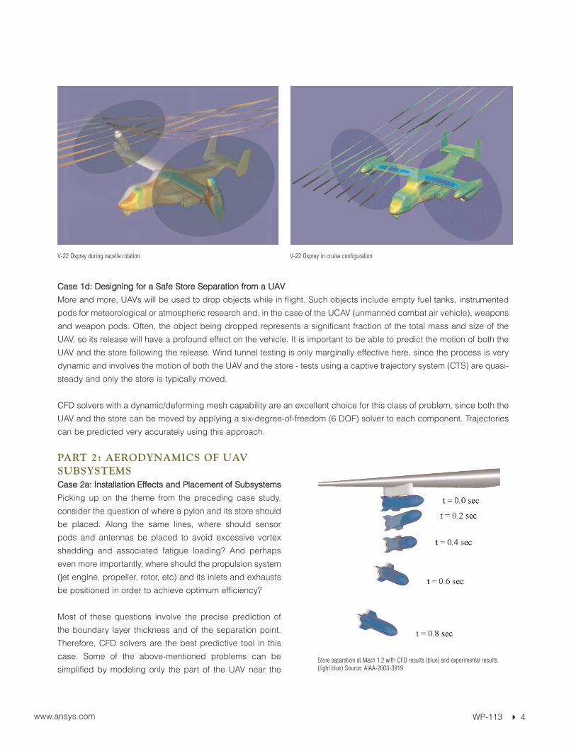
CCaassee 11dd:: DDeessiiggnniinngg ffoorr aa SSaaffee SSttoorree SSeeppaarraattiioonn ffrroomm aa UUAAVV
More and more, UAVs will be used to drop objects while in flight. Such objects include empty fuel tanks, instrumented
pods for meteorological or atmospheric research and, in the case of the UCAV (unmanned combat air vehicle), weapons
and weapon pods. Often, the object being dropped represents a significant fraction of the total mass and size of the
UAV, so its release will have a profound effect on the vehicle. It is important to be able to predict the motion of both the
UAV and the store following the release. Wind tunnel testing is only marginally effective here, since the process is very
dynamic and involves the motion of both the UAV and the store - tests using a captive trajectory system (CTS) are quasi-
steady and only the store is typically moved.
CFD solvers with a dynamic/deforming mesh capability are an excellent choice for this class of problem, since both the
UAV and the store can be moved by applying a six-degree-of-freedom (6 DOF) solver to each component. Trajectories
can be predicted very accurately using this approach.
PART 2: AERODYNAMICS OF UAVSUBSYSTEMS CCaassee 22aa:: IInnssttaallllaattiioonn EEffffeeccttss aanndd PPllaacceemmeenntt ooff SSuubbssyysstteemmss
Picking up on the theme from the preceding case study,
consider the question of where a pylon and its store should
be placed. Along the same lines, where should sensor
pods and antennas be placed to avoid excessive vortex
shedding and associated fatigue loading? And perhaps
even more importantly, where should the propulsion system
(jet engine, propeller, rotor, etc) and its inlets and exhausts
be positioned in order to achieve optimum efficiency?
Most of these questions involve the precise prediction of
the boundary layer thickness and of the separation point.
Therefore, CFD solvers are the best predictive tool in this
case. Some of the above-mentioned problems can be
simplified by modeling only the part of the UAV near the
WP-113 � 4www.ansys.com
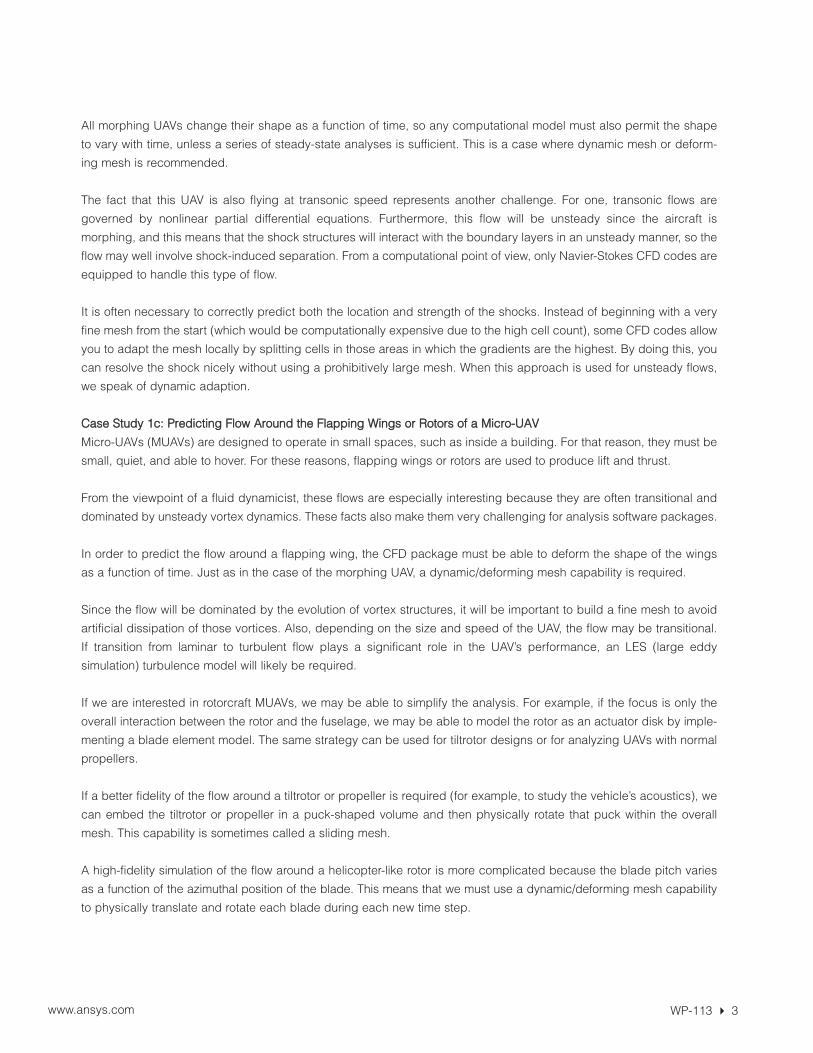
V-22 Osprey during nacelle rotation V-22 Osprey in cruise configuration
Store separation at Mach 1.2 with CFD results (blue) and experimental results(light blue) Source: AIAA-2003-3919
object of interest. In other cases, you may need to
model almost the entire vehicle at low fidelity and then
only place a boundary layer mesh upstream of the
object of interest (for example, upstream of a ram
scoop).
To analyze the full fluid-structure interaction (FSI), the
CFD code should allow for coupling to a CSM/FEA
(computational structural mechanics, finite element
analysis) code, including the interpolation between the
CFD and CSM meshes.
CCaassee 22bb:: DDyynnaammiicc FFoorrcceess DDuuee ttoo TTaannkk SSlloosshhiinngg
During the design of the fuel tanks, it is important to
minimize the sloshing of the fuel in order to avoid large
dynamic forces that affect the stability and control of the
UAV. The behavior of the liquid fuel inside the tank is
modeled using a free surface multiphase model, such
as the VOF (volume of fluid) model. In such a model, the
position of the liquid-gas interface is tracked in time. As
a result, the center of gravity of the liquid is tracked, as
are the forces exerted by the fluid on the tank walls.
Free surface models have many uses in addition to the
sloshing problem. They are used to design the hulls of
planing seaplanes and to predict the wave drag on hulls
of seaplanes in displacement mode and of USVs
(unmanned surface vehicles). They have been used to
predict the breakup and spreading of water dumped
from firefighting UAVs, as well as the breakup and
spreading of fuels near the fuel injectors of IC engines
and jet engines.
CCaassee 22cc:: CCoooolliinngg PPrroobblleemmss aanndd HHeeaatt TTrraannssffeerr
During the design of a UAV, there are numerous heat
transfer problems: the engine, avionics and other elec-
tronics need to be cooled, leading edges may need to
be heated to avoid icing, and exhausts need to be
designed to minimize infrared signatures. CFD has
been successfully used to resolve all of these problems.
With regard to engine cooling, typical challenges
involve the exact placement of the engine and the heat
exchangers within the cowling or nacelle, and the
optimal placement of inlets, scoops, and exhausts. The
WP-113 � 5www.ansys.com
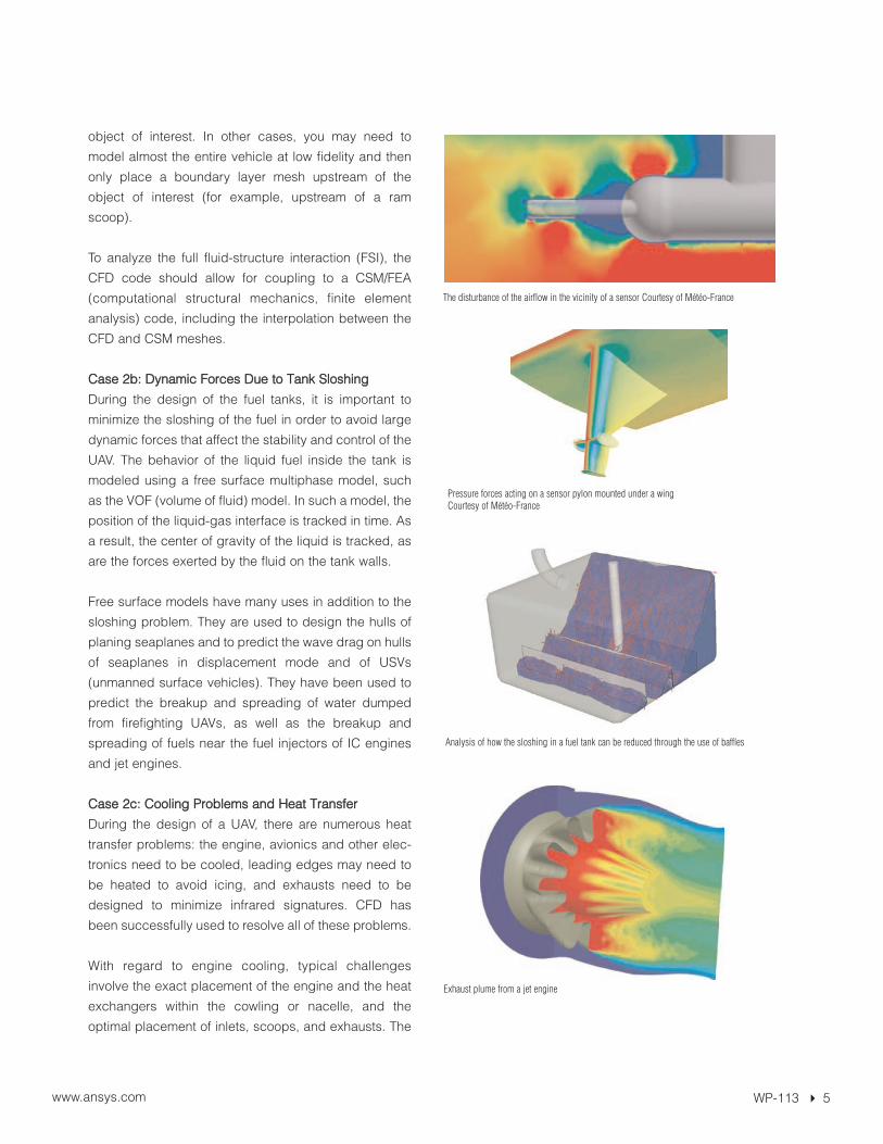
The disturbance of the airflow in the vicinity of a sensor Courtesy of Météo-France
Pressure forces acting on a sensor pylon mounted under a wingCourtesy of Météo-France
Analysis of how the sloshing in a fuel tank can be reduced through the use of baffles
Exhaust plume from a jet engine
WP-113 � 6www.ansys.com
problem is so ubiquitous that it has several names in aerospace jargon, such as “nacelle cooling,” “undercowl flow,” and
“core compartment thermal management.” One of the main difficulties here is the complexity of the CAD geometry – it
requires the CAD operator and the analyst to work together seamlessly. In the CFD environment, radiation models may
be required for this class of problems.
Another problem involving geometric complexity is the cooling of avionics and other on-board electronics. There is an
entire “electronics cooling” industry and its best-known problem may be the cooling of computer CPU boxes. In
airplanes and UAVs, the geometries are usually more complex because of the curviness of the fuselage. As a result, the
meshes will tend to be unstructured instead of consisting of multiple blocks of hexahedral cells.
The same arguments apply to the design of anti-icing systems that are based on bleed air. The hot air is blown into the
intricately shaped cavities within the wings in order to heat the wing skin. An additional challenge here is that both the
high-speed jets and the flows adjacent to the walls must be resolved properly in order to predict plume spreading rates
and wall heat transfer rates. The same stringent requirements apply when you are analyzing the heat transfer from the
engine exhaust plume. One needs to determine the plume and the boundary layers adjacent to the walls that are near
the plume in order to determine the correct wall temperatures. To find out about the heat transfer due to particles (such
as soot particles) in the plume, your CFD code must be able to track particles and account for radiation from those
particles.
CONCLUSION The above case studies demonstrate that CFD is a versatile and essential tool for analyzing many flow problems
involving UAVs and their subsystems. Given that inexpensive computational power is now readily available, CFD has
become a standard tool for use in the design process.
About ANSYS, Inc. ANSYS, Inc., founded in 1970, develops and globally markets engineering simulation software and technologies widely used by engineers and designersacross a broad spectrum of industries. ANSYS focuses on the development ofopen and flexible solutions that enable users to analyze designs directly on thedesktop, providing a comon platform for fast, efficient and cost-consciousproduct development, from design concept to final-stage testing and validation. ANSYS and its global network of channel partners provide sales,support and training for customers. Headquartered in Canonsburg,Pennsylvania, U.S.A., with more than 40 strategic sales locations throughout theworld, ANSYS and its subsidiaries employ approximately 1,400 people and distribute ANSYS products through a network of channel partners in over 40 countries. Visit http://www.ansys.com for more information.
Toll Free U.S.A./Canada:1.866.267.9724Toll Free Mexico:001.866.267.9724Europe:[email protected]
ANSYS, Inc.Southpointe275 Technology DriveCanonsburg, PA [email protected]
www.ansys.com