a web-based temperature monitoring system for the college …
TRANSCRIPT

California State University, San Bernardino California State University, San Bernardino
CSUSB ScholarWorks CSUSB ScholarWorks
Electronic Theses, Projects, and Dissertations Office of Graduate Studies
3-2015
A WEB-BASED TEMPERATURE MONITORING SYSTEM FOR THE A WEB-BASED TEMPERATURE MONITORING SYSTEM FOR THE
COLLEGE OF ARTS AND LETTERS COLLEGE OF ARTS AND LETTERS
Rigoberto Solorio California State University - San Bernardino
Follow this and additional works at: https://scholarworks.lib.csusb.edu/etd
Part of the Databases and Information Systems Commons, Environmental Indicators and Impact
Assessment Commons, Environmental Monitoring Commons, Information Security Commons, OS and
Networks Commons, Other Computer Sciences Commons, Software Engineering Commons, Systems
Architecture Commons, and the Water Resource Management Commons
Recommended Citation Recommended Citation Solorio, Rigoberto, "A WEB-BASED TEMPERATURE MONITORING SYSTEM FOR THE COLLEGE OF ARTS AND LETTERS" (2015). Electronic Theses, Projects, and Dissertations. 129. https://scholarworks.lib.csusb.edu/etd/129
This Thesis is brought to you for free and open access by the Office of Graduate Studies at CSUSB ScholarWorks. It has been accepted for inclusion in Electronic Theses, Projects, and Dissertations by an authorized administrator of CSUSB ScholarWorks. For more information, please contact [email protected].

A WEB-BASED TEMPERATURE MONITORING SYSTEM FOR THE COLLEGE
OF ARTS AND LETTERS
A Project
Presented to the
Faculty of
California State University,
San Bernardino
In Partial Fulfillment
of the Requirements for the Degree
Master of Science
in
Computer Science
by
Rigoberto Solorio
March 2015

A WEB-BASED TEMPERATURE MONITORING SYSTEM FOR THE COLLEGE
OF ARTS AND LETTERS
A Project
Presented to the
Faculty of
California State University,
San Bernardino
by
Rigoberto Solorio
March 2015
Approved by:
David Turner, Advisor, Computer Science and Engineering
Ernesto Gomez, Committee Member
Josephine Mendoza, Committee Member

© 2015 Rigoberto Solorio

iii
ABSTRACT
In general, server rooms have restricted access requiring that staff
possess access codes, keys, etc. Normally, only administrators are provided
access to protect the physical hardware and the data stored in the servers.
Servers also have firewalls to restrict outsiders from accessing them via the
Internet. Servers also cost a lot of money. For this reason, server rooms also
need to be protected against overheating. This will prolong the lifecycle of the
units and can prevent data loss from hardware failure.
The California State University San Bernardino (CSUSB), Specifically the
College of Arts and Letters server room has faced power failures that affected
the Air Conditioning Unit (AC) and as a result the room became overheated for a
long time, causing hardware failure to server units. This is why this project is
important for the College and needs to be implemented as soon as possible.
The administrator’s old method of controlling server room temperature
was by manually adjusting the temperature box inside of the server room. Now it
can be controlled and monitored using remote access.
The purpose of A Web-Based Temperature Monitoring System for the
College of Arts and Letters proposed in this project is to allow users to monitor
the server room temperature through a website by using any computer or mobile
device that has Internet access. Also, this system notifies users when the room
attains a critical temperature by sending an email/text to the server room
administrator.

iv
A Web-Based Temperature Monitoring System for the College of Arts and
Letters project is for the exclusive use of the College of Arts & Letters (CAL)
server room. The administrator is the only person that can grant access to others
by creating a proper account.
For this project three prototypes will be implemented, first to measure the
current server room temperature, the second to show the temperature history of
the room, and third to use the built-in search system to locate times that given
temperatures were attained.

v
ACKNOWLEDGMENTS
I am dedicating my work to my wife, Graciela Lopez, my daughters
Stephanie Solorio, Karen Solorio, Itzel Solorio and my boy Rigoberto Solorio Jr.
who always believe in me. And of course to my mother, Rosa Zendejas, and my
father, Alfredo Solorio. Also to my brothers Gilberto Solorio, Victor Solorio and
Carlos Solorio I could not have done this work without them.
To my adviser Dr. David Turner, who always gave me great ideas and
helped me to improve my skills. I believe strongly that a person can only go so
far unless they surround themselves with great people. I would also like to thank
my constant friend, Ken Han, for his motivation and unconditional support. I
cannot thank my great friend, Alysha Timmons, enough for her numerous hours
spent editing. I would also like to thank Dr. Jaqueline Rhodes and Nick Valentin
for being very nice to me and for all their help. I thank my valuable committee
members Dr. Ernesto Gomez and Dr. Josephine Mendoza. Also I would like to
thank the CAL Deans for their support.
Lastly I thank all my friends and professors who in one way or another
encourage me to continue my education. Thank you to Robert Clinton who was
my first mentor at RCC and encouraged me to get my Master’s degree. Being the
first family member graduating from college is an amazing experience for me –
an experience that I want to pass on to my family. Here it is!
Rigoberto Solorio

vi
TABLE OF CONTENTS
ABSTRACT ................................................................................................. iii
ACKNOWLEDGMENTS .............................................................................. v
LIST OF TABLES ........................................................................................ x
LIST OF FIGURES ...................................................................................... xi
CHAPTER ONE: SOFTWARE REQUIREMENTS SPECIFICATION
1.1 Introduction .................................................................................. 1
1.2 Purpose of this Project ................................................................ 2
1.3 Context of the Problem and Previous Research .......................... 3
1.3.1 Other Projects Results ...................................................... 4
1.4 Project Products .......................................................................... 6
1.5 Definition of Terms and Abbreviations ......................................... 6
1.6 Preliminary Design ....................................................................... 8
1.6.1 User Characteristics .......................................................... 8
1.6.1.1 User ..................................................................... 8
1.6.1.2 Administrator ........................................................ 9
CHAPTER TWO: SOFTWARE DESIGN AND USERS ACCESS
2.1 Architecture .................................................................................. 11
2.2 User Access ................................................................................. 12
2.2.1 Client Side ........................................................................ 12
2.2.2 Server Side ....................................................................... 12
2.2.3 Database Interaction ......................................................... 18

vii
2.3 Database Design ......................................................................... 23
2.3.1 Database Schema Conceptual Model............................... 23
2.3.2 Database Schema Logical Model ..................................... 26
2.4 System Components ................................................................... 28
CHAPTER THREE: HARDWARE AND SOFTWARE
3.1 Hardware ..................................................................................... 29
3.1.1 Arduino Uno ...................................................................... 29
3.1.1.1 Arduino Uno Components ................................... 30
3.1.2 Arduino Ethernet Shield .................................................... 32
3.1.3 Carbon Resistor ................................................................ 33
3.1.3.1 Resistor Color Code ............................................ 34
3.1.4 Thermistor ......................................................................... 35
3.1.5 Assembling Parts .............................................................. 36
3.2 Software ....................................................................................... 40
3.2.1 Temperature Calibration ................................................... 42
3.2.2 Complete Modified Arduino Code ..................................... 43
CHAPTER FOUR: IMPLEMENTATION
4.1 Introduction .................................................................................. 51
4.2 Basic Interface ............................................................................. 51
4.2.1 Administrator/User Login Page ......................................... 51
4.2.1.1 Administrator/User Access .................................. 52
4.2.2 Search Engine Functionality ............................................. 53

viii
4.2.3 Remote Access ................................................................. 55
4.2.4 System Warning Notification ............................................ 59
CHAPTER FIVE: VERIFICATION AND VALIDATION
5.1 Unit Test ...................................................................................... 61
CHAPTER SIX: SYSTEM CONFIGURATION AND MAINTENANCE MANUAL 6.1 Software Installation ..................................................................... 65
6.1.1 CentOS Installation ........................................................... 65
6.1.2 System Updated ............................................................... 73
6.1.3 Firewall Configuration ....................................................... 75
6.1.4 Network Configuration ...................................................... 76
6.1.5 Apache Server Installation ................................................ 81
6.1.6 MySQL Installation ............................................................ 84
6.1.7 PHP Installation ................................................................ 87
6.1.8 jQuery Libraries ................................................................ 88
6.2 Server Host Names ...................................................................... 89
6.2.1 Caltemp.csusb.edu and Caltempsensor1.csusb.edu ........ 89
6.3 Backup And Restore .................................................................... 92
6.3.1 System Backup ................................................................. 92
6.3.2 Database Backup ............................................................. 92
6.3.3 System Restore ................................................................ 93
6.3.4 Database Restore ............................................................. 93

ix
CHAPTER SEVEN: CONCLUSION AND FUTURE DIRECTIONS
7.1 Conclusion ................................................................................... 94
REFERENCES ........................................................................................ 95

x
LIST OF TABLES
Table 1. Comparison Results with this Project ............................................. 5
Table 2. Server Side login_proc.php Code ..................................................13
Table 3. Server Databases ...........................................................................18
Table 4. Relevant Databases and their Tables .............................................19
Table 5. Database Side login_sess.php Code ..............................................20
Table 6. Database Side sess.php Code .......................................................21
Table 7. Temp Table ....................................................................................26
Table 8. Temp Table Description ..................................................................26
Table 9. Administrator and User Permissions...............................................27
Table 10. Arduino Uno Components ............................................................31
Table 11. Modified Arduino Uno Source Code .............................................44
Table 12. Unit Test Results (Forms) .............................................................62

xi
LIST OF FIGURES
Figure 1. User Use Case Diagram ............................................................... 9
Figure 2. Administrator Use Case Diagram ................................................. 10 Figure 3. Deployment Diagram ..................................................................... 11 Figure 4. Client Side Login Code ................................................................. 12 Figure 5. Flowchart Diagram ........................................................................ 25 Figure 6. Arduino Uno Board ........................................................................ 30 Figure 7. Ethernet Shield .............................................................................. 33 Figure 8. Resistor Color Code ...................................................................... 35 Figure 9. Thermistor ..................................................................................... 36 Figure 10. Arduino Uno and Ethernet Shield Assembling ............................. 38 Figure 11. Arduino, Ethernet Shield, Resistor and Thermistor Assembled ... 39 Figure 12. All Parts Connected to the Running Server ................................. 40 Figure 13. Original Arduino Code ................................................................. 43 Figure 14. Thermometer ............................................................................... 49 Figure 15. A, B, and C Fixed Values ............................................................ 50 Figure 16. A Web-Based Temperature Monitoring System for CAL Login ... 52 Figure 17. A Web-Based Temperature Monitoring System for CAL Page .... 52 Figure 18. A Web-Based Temperature Monitoring System for CAL Search . 53 Figure 19. Temperature Searched for 17-10-2014 at 6:09 PM ..................... 54 Figure 20. Temperature Showing at 17-10-2014 at 6:09 PM ........................ 54 Figure 21. Access Topology ......................................................................... 55

xii
Figure 22. PuTTy Login Interface ................................................................. 56 Figure 23. Wireless Login for Remote Access .............................................. 57 Figure 24. VPN_Pulse Client Configuration .................................................. 58 Figure 25. VPN_Pusle Client Connected ...................................................... 59 Figure 26. System Server Email Notification ................................................ 60 Figure 27. CentOS Installation Begins .......................................................... 66 Figure 28. CentOS Installation linux text ...................................................... 67 Figure 29. CentOS Installation Skip for Media Test ...................................... 68 Figure 30. CentOS Installation for English Language ................................... 69 Figure 31. CentOS Installation Root Password ............................................ 71 Figure 32. CentOS Installation in Progress .................................................. 72 Figure 33. CentOS Reboot ........................................................................... 73 Figure 34. System Updating ......................................................................... 74 Figure 35. System Rebooted ........................................................................ 75 Figure 36. System Firewall Configuration ..................................................... 76 Figure 37. System Network Configuration .................................................... 77 Figure 38. System Hostname Configuration ................................................. 78 Figure 39. System Save Configured Settings ............................................... 79 Figure 40. System DNS Configuration .......................................................... 80 Figure 41. CentOS Login Screen .................................................................. 81 Figure 42. Apache Server IP Verification Screen ......................................... 83 Figure 43. Apache Server Test Successfully Works ..................................... 84

xiii
Figure 44. MySQL Login Screen .................................................................. 86 Figure 45. PHP Version Verification Screen ................................................ 88 Figure 46. jQuery JavaScript Libraries ......................................................... 89 Figure 47. Linux Host Name Configuration ................................................... 90 Figure 48. Accessing Temperature Data Directly ......................................... 91

1
CHAPTER ONE
SOFTWARE REQUIREMENTS SPECIFICATION
1.1 Introduction
The purpose of this project is to improve the current form of monitoring the
temperature in the College of Arts & Letters server room. Currently, the
temperature can only be read from the box attached to the wall. The technician
must physically visit the server room throughout the day adjusting the
temperature, as needed. Another reason to implement this prototype is due to
the fact that the A/C unit is constantly failing causing the server room to overheat,
especially during the summer.
Keeping server room temperature at low level helps hardware equipment
to function better and to prolong the life of units. Maintaining units in a cooler
environment also increases the company’s revenue by avoiding overheating of
the hardware equipment, which in many cases is the main cause of hardware
failure.
In order to address the issue, Management has to choose to place a
person in the server room to monitor the temperature, or develop a system that
can monitor the temperature from remote places at any given time (to save on
human capital) [8].
The main purpose of this system model is to make it easy for the user to
view the current server room temperature by remote access. A Web-Based

2
Temperature Monitoring System for the College of Arts and Letters can be
accessed anywhere and anytime through the Internet, thus saving human
expenses. A Web-Based Temperature Monitoring System for the College of Arts
and Letters is one type of temperature recorder that monitors a temperature in a
room, stores the data into a database, and displays the current temperature on
the website through a web server. The system will continuously monitor the
temperature condition of the server room allowing the data to be monitored at
anytime and anywhere from the Internet [8].
Similar temperature monitoring systems are widely used in many
organizations with the purpose of maintaining goods, such as food warehouses,
drink industries, vegetable refrigeration units, etc.
1.2 Purpose of this Project
The purpose of A Web-Based Temperature Monitoring System for the
College of Arts and Letters project is to allow users to supervise the College of
Arts and Letters server room temperature 24/7 from anywhere through internet
log in. This project of Temperature Monitoring System also has an email warning
notification feature to inform technician staff when a critical temperature has been
reached in the room.
By monitoring this interface, IT staff can view the current CAL server room
temperature in numeric digital format and graphical display. In addition, the user

3
can use the search engine to search the historical temperature records saved in
the database.
A Web-Based Temperature Monitoring System for the College of Arts and
Letters is to function as a standalone website, it means that it can be functioning
without close supervision 24/7.
Research for the best technology that can be used to achieve the above
description was be conducted. The following documentation represents a client-
server based approach.
1.3 Context of the Problem and Previous Research
Since the beginning of the College of Arts and Letters, the server room
temperature has being facing power crises, causing hardware failures and
minimizing the equipment life cycle. Now with the Web-Based Server Room
Temperature project, we expect fewer downtimes and increased functionality.
The crux of the problem is how to supervise the server room temperature
24/7 from a remote location. It is inefficient to track server room temperature in
manual ways. Currently, the technician must physically visit the server room
throughout the day adjusting the temperature, as needed. The system and
technician needs to be in communication with the server room constantly. The
availability of a web-based system to enable viewing of the temperature
performance and records is more reliable and efficient.

4
1.3.1 Other Projects Results
The purpose of comparing is to make sure that my project has similar
results using different software and different hardware applying same concepts of
previous projects. According of In M. Kassim, M.N. Ismail and C.K.H. Che Ku
Yahaya article, they mention that measuring temperature using an iButton sensor
allows access to data using LAN network protocols, and is not accessible
through the Internet compared to Web-Based Temperature Monitoring [8].
Another prototype is the Speech Synthesized Temperature Sensor alerts
which measure temperature changes using a verbal message when a change
occurs, but it is not accessible through a web browser. This sensor is mostly
used to monitor temperature changes in a car, power plant [8] or laboratory
facilities.
The last comparison prototype is X-10 Based Remote Temperature
Monitoring System, which gives the same results as the Web-Based
Temperature Monitoring. The main difference is that it uses different devices to
monitor the temperatures and the temperature changes are updated
automatically in the browser without needing to refresh a web page.
Table 1 shows the comparison of the three analyzed systems with this project.
This is an extension of a table presented in [8].

5
Table 1. Comparison Results with this Project
Project /Description
Web-based Temperature Monitoring System for the CAL
Automated
Temp/
Tracking/
System
Speech
Temp/
Sensor
X-10 Based Remote
Temperature
Monitoritoring
System
Concept In a room/ Arduino/ storing data -DB
Monitoring/
Hospitals
Inveronme-
Tal/via
Verbal message
In a room/
X-10
/storing data-DB
Device Arduino Uno
Ethernet Shield
Resistor
Thermistor
iButton/
Micro-
Controller
(TINI)
Chip
Microprocessor
X-10
Transmitter
Software MySQL
PHP
Apache/Centos
CSS
JavaScript
Java
ApacheTC
JavaSevlet
Pages
MySQL
Java
JavaSevlet
JavaSever
Pages
MySQL
PHP
Apache

6
1.4 Project Products
This project resulted in the following products:
Web Application: A web application with a system interface, using a
MySQL database for storing data, CentOS operation system platform,
Arduino Uno cell ship unit, and Hypertext Preprocessor (PHP) source
scripting language. This web application should achieve the needs of a
communication interface between users and technicians/managers. Its
use as an online service will be exclusive to the College of Arts and
Letters' technician and Dean’s office.
System Manual: this project with design details and specifications will be
kept by the Computer Science and Engineering Department of CSUSB.
1.5 Definition of Terms and Abbreviations
This section presents the definitions and acronyms that will be used
further in this document.
API – Application Programming Interface
Arduino Uno – a USB single-board microcontroller, intended to make building
interactive objects or environments more accessible.
Browser – A program that accesses and displays the website to view the current
server room temperature chart.
CAL – College of Arts and Letters

7
CentOS – Linux based Red Hat operating system
CSUSB – California State University of San Bernardino
Hypertext Markup Language (HTML) – A markup language used to structure text
and multimedia documents and to set up hypertext links between documents.
IEEE – Institute of Electrical and Electronics Engineers
ITC – Information Technology Consultant
MySQL – structured query language. Is the most popular database system used
with PHP that synchronizes with the web and runs on the server
PHP – Hypertext Preprocessor, scripts that are executed on the server
PWM – Pulse Width Modulation
SRS – Software Requirements Specification
SSH – Secure Shell
VPN – Virtual Private Network

8
1.6 Preliminary Design
There are two types of user classes implemented in this project:
1. User/Viewer.
2. System administrator.
A menu page is associated with each type of user.
1.6.1 Users Characteristics
Users of the Web-Based Temperature Monitoring System for the College
of Arts and Letters would fall into one of the following groups:
1.6.1.1 User. The user in the system is like a customer. To use the
system, the user needs to obtain a login name and password from the
administrator.
The user’s view after login is the main page of Web-Based Temperature
Monitoring System for the College of Arts and Letters (CAL) project. User can
read and monitor current temperature, search for old temperature at specific day
and time by using the search engine, and to logout after all. See Figure 1.

9
Figure 1. User Use Case Diagram
1.6.1.2 Administrator. The administrator has the functionality of a user with
the additional privileges to add/edit a user account and update the system.
Admins also have the ability to add, edit, and delete user accounts. See
Figure 2.

10
Figure 2. Administrator Use Case Diagram

11
CHAPTER TWO
SOFTWARE DESIGN AND USERS ACCESS
2.1 Architecture
A Web-Based Temperature Monitoring System for the College of Arts and
Letters project has 3 main components: web-browser, Client side, and Arduino
unit. Figures 3 and 4 best describe the architecture sides:
Figure 3. Deployment Diagram

12
2.2 User Access
2.2.1 Client Side
Client side connect to the Internet thought the browser using javascript
code. In order to the user to access the Web-Based Temperature Monitoring
System for the College of Arts and Letters, he or she has to have a proper
account created by the system administrator. The piece of code that enables the
user to login is in Figure 4.
Figure 4. Client Side Login Code
2.2.2 Server Side
Server side controls the content or appearance of Web pages through the
use of php code, small programs that run on the Web server to modify the Web
page before it is sent to the user who requested it.

13
The server side is the server that contains the CentOS apache web server
module, which runs the application’s php code. The php page is responsible for
processing the login request and restricting access to users. The php code is
showing below in Table 2.
Table 2. Server Side login_proc.php Code
//login_proc.php to login
// sess.php for session data and db connection
//url on successfull redirect
$url = 'portal.php';
//include session
include 'tools/login/login_sess.php'; //starts the session
//check to see if username or password was left blank
if(empty($_POST['username']))
echo '<meta http-equiv="refresh" content="2; URL=monitor.php">';
die('username blank');
if(empty($_POST['password']))
echo '<meta http-equiv="refresh" content="2;
URL=monitor.php">';

14
die('password blank');
/*This is the new way to conenct to mysql as compared to the methods
used in*/
// /var/www/html/monitor/tools/db_connections_dbuser.php
$login = mysqli_connect("localhost", "login", "i08836v97KuPE1c");
mysqli_select_db('phpuser', $login);
//and the new way to scrub input
$un = mysqli_real_escape_string($login
,htmlspecialchars($_POST['username']));
$pw =
mysqli_real_escape_string($login,htmlspecialchars($_POST['password']));
//the new way to disconnect from mysql
mysqli_close($login);
//include the connection to the users table
include 'tools/db_connections/dbuser.php';
//get all users from database
$uresult = mysql_query("select username from user");
//close connection to user database
mysql_close($login);
//check to see if input matches existing user
while ($users = mysql_fetch_row($uresult))

15
//check if username exists in database
if ($users[0] == $un)
/*check for login attempts ## consider moving this out of loop to get ALL
attempts!!! */
//include attempt.php page
include 'tools/login/attempt.php';
//calls attempt function given username
$check = attempt($users[0]);
//if too many bad attempts have been made
if ($check == false)
echo '<meta http-equiv="refresh" content="2;
URL=index.php">';
die('too many login attempts');
//#######grab password list### connect to user database
include 'tools/db_connections/dbuser.php';
//get password given confirmed username(not using direct input form user)

16
$result = mysql_query("select username, user_type,
password as 'pw' from user where username = '$users[0]'") or
die(mysql_error());
$array_r = mysql_fetch_array($result);
//close user db connection
mysql_close($login);
/*########if user and pass match, initilize session and proceed#######*/
//recreate hash using password
$hash = crypt($pw, $array_r['pw']);
//check to see if hashes match
if ($hash == $array_r['pw'])
/*passwords match then create session and set
variables*/
$type = $array_r['user_type'];
$uname = $array_r['username'];
$_SESSION['type'] = $type;
$_SESSION['user'] = $uname;
echo '<meta http-equiv="refresh" content="0;
URL='.$url.'">';
/*if the passwords dont match then log the attempt, kill the
page, and redirect*/

17
else
include 'tools/db_connections/dbattempt.php';
$check = addattempt($users[0]);
echo '<meta http-equiv="refresh" content="2;
URL=index.php">';
die('bad password');
mysql_close($attmpt);
//else bad username
/*include 'tools/db_connections/dbattempt.php';
$check = addattempt($users[0]);
mysql_close($attmpt);*/
echo '<meta http-equiv="refresh" content="2; URL=index.php">';
die('bad username');
?>

18
2.2.3 Database Interaction
This application shares the same phpuser and login_attempt databases
used by other system administration applications in the College of Arts and
Letters. This application also uses the monitor database to store historical
temperature data. See Table 3. See also Table 4 for the other database located
in the server.
Table 3. Server Databases

19
Table 4. Relevant Databases and their Tables

20
The database interaction is performed within three php files that allow
users to login a secure way. These files are named sess.php, login_sess.php
and login_proc.php (Table 2) files.
The login_sess.php file is responsible to create a new login session each
time the user logs in and to delete the old session. See Table 5.
Table 5. Database Side login_sess.php Code
* Description: session for the login_proc script
* creates a secure session
*/
$session_name = ‘sec_monitor_session’; /* Set a custom session
name*/
$secure = false; // Set to true if using https.
$httponly = true; /* This stops javascript being able to access the
session id*/
ini_set(‘session.use_only_cookies’, 1); /* Forces sessions to only
use cookies/*
$cookieParams = session_get_cookie_params(); /*Gets current
cookies parameter*/
session_set_cookie_params($cookieParams[“lifetime”],
$cookieParams[“path”], $cookieParams[“domain”], $secure, $httponly);

21
session_name($session_name); /* Sets the session name to the
one set above*/
session_start(); // Start the php session
session_regenerate_id(true); /* regenerated the session, delete
the old one*/
?>
The sess.php file is responsible for validating username and password. If
the credentials are invalid a login error will be given. Sess.php file interacts with
the login_sess.php file to create a user login session. This file also allows users
to access the database depending on their authority level. The piece of code is
shown in Table 6.
Table 6. Database Side sess.php Code
if(isset($_SESSION['type'])) /*if type has value then load value
into variable*/
$type = $_SESSION['type'];
$user = $_SESSION['user'];
if ($type == 'senior')

22
include
'/var/www/html/monitor/tools/db_connections/dbsenior_monitor.php';
else if ($type == 'junior')
include
'/var/www/html/monitor/tools/db_connections/dbjunior_monitor.php';
else if ($type == 'view')
include
'/var/www/html/monitor/tools/db_connections/dbview_only.php';
else
echo '<meta http-equiv="refresh" content="2;
URL=index.php">';
die('error you are not logged in');
//$table = $_SESSION['table'];

23
2.3 Database Design
2.3.1 Database Schema Conceptual Model
In designing the schema of this project, the following parts are identified:
1. Users: Users who have permission to view should be identified to the
system. By entering valid user credentials, the system will allow users to
view the Web-Based Temperature Monitoring System for the College of
Arts and Letters website. Users are also allowed to use the search engine
to recall historical data from the server database system.
2. System Response: The Arduino shell sensor generates data that is stored
into the database system. The system is programmed to read temperature
data and display it in numerical format reflected in a 2-dimensional x-y
graphical chart.
The system is also allowed to send an email notification to the ITC when
the temperature reaches an administrator-specified value.
3. History: The system will maintain the history of each login request.
The Flowchart diagram in Figure 5 represents the user’s sequential steps
that have to be followed in order to use the Web-Based Temperature Monitoring
System for the College of Arts and Letters. The flowchart diagram has the
following symbols:
The flow line symbol is an arrow connector symbol which shows the
direction of the process.

24
The Start/End symbol is an oval shape which represents the
start/end of a process point.
The decision symbol is a diamond shape which indicates a
question to be answered – could be yes\no or true\false.
The input/output symbol is a parallelogram shape which indicates
input/output of data.
The process symbol is a rectangle shape which indicates a
process, action, or function. It is the most widely used symbol in the flowchart
model.

25
Figure 5. Flowchart Diagram
The system administrator uses the same process to log into the system.
The difference between users and the administrator is that the administrator has
the permission to access the database and the system source code to update or
modify it, create/edit a username and grant users permission. See Figure 6.
The system is a standalone device, which means that it is able to function
independently without close supervision.

26
2.3.2 Database Schema Logical Model
The Use Case diagram that is shown in Figure 1 maps to the following
relational table design. The monitor database contains a table named Temp as
showing in the Table 7.
Table 7. Temp Table
The Temp table contains a primary key PRI (id) for both the user and
administrator as shown in Table 8.
Table 8. Temp Table Description

27
The administrator of the Web-Based Temperature Monitoring System for
the College of Arts and Letters (as shown in Figure 2) is in charge of managing
and maintaining the system code, assigning user permissions, upgrading the
system, and modifying the database. The User has restricted control and is only
allowed to view the information online and search the database. See Table 9.
Table 9. Administrator and User Permissions
Permissions
Administrator Full Control
- Add user/Delete user/Edit
-View current temperature and
historical temperature
- Use the search function
User Restricted Control
-View current temperature and
historical temperature
-Use the search function

28
2.4 System Components
The following technologies were implemented into the project:
MySQL is used to store data in the database system. MySQL is an open
source software and is used as a multi-user database.
JavaScript is an important application tool to sync between web pages
and users through the browser.
Internet Browser: Has no browser constraints.
CentOS 6.4
Database: MySQL.
Web Server: Apache
jQuery Library: jquery-1.10.2.js, jquery.thrmometer.js, jquery-ui-
1.10.4.custom.js

29
CHAPTER THREE
HARDWARE AND SOFTWARE
3.1 Hardware
The Web-based Temperature Monitoring System for the College of Arts
and Letters is built with Arduino Uno, Ethernet shield, thermistor, a carbon
resistor, Web server, and database server.
The chapter focuses on describing the Arduino Uno, Ethernet shield,
thermistor and carbon resistor. For descriptions of the Web server and database
server see chapter 6.
3.1.1 Arduino Uno
Arduino Uno is an open source product and one of the most used
microcontroller chips to measure environmental factors such as temperature,
wind speed, and pressure, etc. The Arduino architecture is based on the
ATmega328 (datasheet) [2]. It contains 14 digital input/output pins connector, a
total of 6 analog inputs. Arduino Uno is built with USB connection, an
independent power jack, and a reset button. Arduino Uno comes with a program
in C programming language, which needs to be modified to measure and
transmit room temperature data to the Web server. Figure 6 shows the Arduino
board and its components.

30
Figure 6. Arduino Uno Board
3.1.1.1 Arduino Uno Components
The following hardware components are interconnected to povide
temperature data to Web–Based Temperature Monitoring System:
1. Arduino Uno USB Board
2. Arduino Ethernet Shield
3. Semiconductor RC1/4103JB Temperature Sensor
4. Ohm resistor A 4.7 K
5. Server unit (Apache CentOS ver6.4)
6. Ethernet cable CAT 6

31
See Table 10 for more features of the Arduino Uno.
Table 10. Arduino Uno Components [2]
Components Characteristics
Microcontroller ATMega328
Operating Voltage 5V
Input Voltage (recommended) 7-12V
Input Voltage (limits) 6-20V
Digital I/O Pins 14
Analog Input Pins 6
DC Current per I/O Pin 40mA
DC Current for 3.3V Pin 50mA
Flash Memory 32Kb
SRAM 2Kb
Clock Speed 16MHz

32
3.1.2 Arduino Ethernet Shield
The Arduino Ethernet Shield allows easy connection to the internet. This
component enables Arduino to send and receive data from anywhere in the world
with an internet connection.
The two parts (Arduino Uno board and Arduino Ethernet Shield) are
assembled together for the purpose of this project. See Figure 6 and Figure 7.
Both parts (Arduino Uno and Ethernet shield) are connected using the male pins
of the Ethernet shield and the 14 digital input/output of Arduino Uno, as showing
in Figure 7.

33
Figure 7. Ethernet Shield
3.1.3 Carbon Resistor
The main advantages of the parts used to build the server room
temperature monitoring system is that they are very low cost and easy to find in
most local hardware stores.

34
Carbon Resistor is mainly made of a carbon clay composition covered
with a plastic case. The lead of the resistor is made of tinned copper. One of
main advantages of these resistors are that they are easily available in local
markets at a very low cost and are very durable in extreme environment
conditions. Its chemical composition of carbon clay and copper make it very
temperature sensitive [6].
3.1.3.1 Resistor Color Code. In each carbon resistor cylinder are four
different color bands, each color represents a unique output numerical digit. In
this project I used a resistor with Gray, Black, Violet and Yellow color.
The overall color resistor pattern value are, Black ⇒ 0, Brown ⇒ 1, Red ⇒
2, Orange ⇒ 3, Yellow ⇒ 4, Green ⇒ 5,Blue ⇒ 6, Violet ⇒ 7 Gray ⇒ 8, White ⇒
9.
Defining the color we have that the first and second color bands indicate a
two digit number, for example the number 80 comes from color Gray=>8 and
color Black=>0, because 0 is a multiple of any positive integer so the
combination with the third color (Violet=>7) which indicates the power of ten as
multiplier, we have 107. So the total electrical residence is 80 X 107 Ω. And as a
final color we have the fourth color band which indicates the tolerance or
resistance which value varies between ± 5 % as margin error [6]. See Figure 8.

35
Figure 8. Resistor Color Code
3.1.4 Thermistor
A thermistor is a very sensitive thermal mini-resistor whose main function
is to perceive small energy changes in the surrounding area. Its cost is very low,
easy to find at most electronic hardware stores, and its functionality is for a long
period of time [10]. See Figure 9.

36
Figure 9. Thermistor
3.1.5 Assembling Parts
In the assembly process of the four main parts I assembled the Arduino
Uno, Ethernet shield, resistor and thermistor in four steps.
First, I assembled the Ethernet shield on top of the Arduino Uno making
sure each pin of the Ethernet shield went inside of its respective Arduino hole or
node. The connection between the two components is formed by putting each
Ethernet shield pin or legs inside of the corresponding Arduino nodes. On the
Arduino board, a node is the row of holes that is connected by the strip of metal
underneath [6]. See Figure 10.

37
After the Arduino Uno and Ethernet shield were assembled together
(Ethernet shield on top of the Arduino Uno board) I proceeded to assemble the
resistor and the thermistor units. As you can see on Figure 11 and Figure 12.
To do this, as first step I numbered the holes or nodes from both Arduino
Uno and Ethernet shield to make it easy to understand. Second, by rolling one
leg of each unit (of the resistor and thermistor) together and sticking them into
the node nine of the Ethernet shield. Third, the other leg of the thermistor goes
into the node number five of the Ethernet shield. And fourth, the other single leg
of the resistor goes into the node number six of the Ethernet shield. See figure
11. Also Figure 12 shows all four components (Arduino Uno, Ethernet Shield,
Resistor, and Thermistor) assembled together and are connected to the running
server.

38
Figure 10. Arduino and Ethernet Shield Assembling

39
Figure 11. Arduino Uno, Ethernet Shield, Resistor, and Thermistor Assembled

40
Figure 12. All Parts Connected to the Running Server
3.2 Software
The project utilizes MySQL, Cascading Style Sheets (CSS), Hypertext
Preprocessor (PHP), and Apache\CentOS to develop a system that will capture
data from the Temperature Sensor, save it into the database and display it to the
webpage. In order to monitor the temperature, specific programming needs to be
used to allow the temperature sensor hardware to interface with the system and
display it via the web. A Web-Based Temperature Monitoring System for the
College of Arts and Letters consists of the Microcontroller Programming,
Carbon Resistor
Thermistor Sensor

41
database system, and the web page development. Each of these require
different languages for coding.
In the Web-Based Temperature Monitoring System for the College of Arts
and Letters project, the following elements are implemented in order to reach the
project mission.
1. Internet Browser – software application for displaying information on
the World Wide Web. This project does not have any known browser
constraints.
2. CentOS 6.4 Version – an open source operation system which is
based on a Linux platform. CentOS has a high standard of readability
interacting with MySQL databases and with PHP as well.
3. MySQL – an open source engine, whose main purpose is to store data
in the form of a database.
4. Web Server – a PC computer system that processes requests via an
HTTP protocol. Its main purpose is to distribute information through the
internet.
5. JavaScript (Libraries) – is a code that runs inside the browser to
display temperature graphs and view data from the webserver.
6. PHP – a server language to generate web pages that incorporate
information from the database.

42
7. Arduino Uno Code– is written in C language and runs in the Arduino
unit to control temperature data capture and transmission to the
webserver.
3.2.1 Temperature Calibration
To measure the authentic server room temperature I had to modify the
Arduino C code downloaded from the Arduino website. The temperature
calibration is based on the Steinhart-Hart equation, which is a model of
resistance measured by a semiconductor at different temperatures. The Steinhart
–Hart equation is: Temperature (T) in Kelvin = 1 / A + B[ln(R)] + C[ln(R)]^3
where A = 0.001129148, B = 0.000234125, C = 8.76741E-08. Where A, B and C
are the coefficients of the Steinhart-Hart equation, T is the temperature (in
Kelvin) and R stand for the resistance of the semiconductor [2]. The original code
downloaded from www.arduino.cc is in Figure 13.

43
Figure 13. Original Arduino Code
3.2.2 Complete Modified Arduino Code
The Modified Arduino code that is running in the server is shown in Table
11, next page.
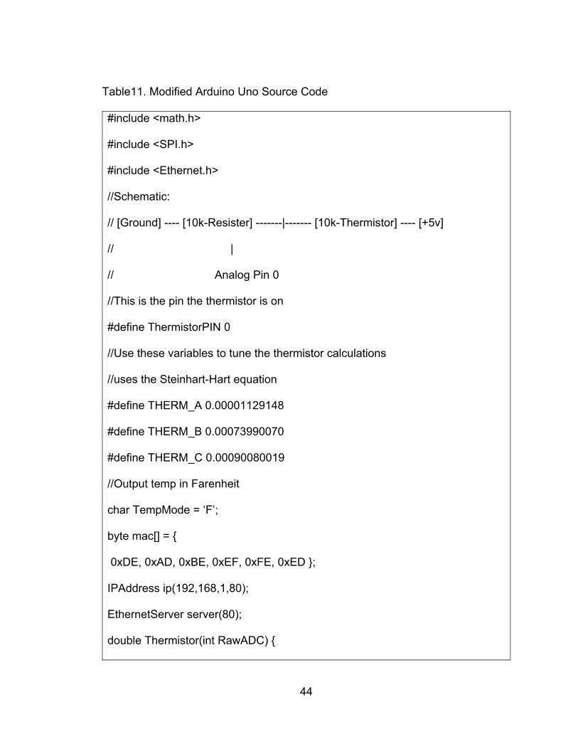
44
Table11. Modified Arduino Uno Source Code
#include <math.h>
#include <SPI.h>
#include <Ethernet.h>
//Schematic:
// [Ground] ---- [10k-Resister] -------|------- [10k-Thermistor] ---- [+5v]
// |
// Analog Pin 0
//This is the pin the thermistor is on
#define ThermistorPIN 0
//Use these variables to tune the thermistor calculations
//uses the Steinhart-Hart equation
#define THERM_A 0.00001129148
#define THERM_B 0.00073990070
#define THERM_C 0.00090080019
//Output temp in Farenheit
char TempMode = ‘F’;
byte mac[] =
0xDE, 0xAD, 0xBE, 0xEF, 0xFE, 0xED ;
IPAddress ip(192,168,1,80);
EthernetServer server(80);
double Thermistor(int RawADC)

45
long Resistance;
double Temp;
Resistance=((10240000/RawADC) – 1000);
Temp = log(Resistance);
Temp = 1/ (THERM_A + (THERM_B * Temp) + (THERM_C * Temp * Temp *
Temp));
Temp = Temp – 273.15;
//Temp is now the temperature in Celsius
return Temp;
double GetTemp()
double temp;
temp = Thermistor(analogRead(ThermistorPIN));
if(TempMode == ‘C’) //if we want celcius
return temp;
else
temp = (temp * 9.0)/ 5.0 + 32.0;
return temp;

46
void setup()
Serial.begin(9600);
Ethernet.begin(mac, ip);
server.begin();
Serial.print(“Server is at “);
Serial.println(Ethernet.localIP());
void loop()
EthernetClient client = server.available();
if (client)
Serial.println(“new client”);
boolean currentLineIsBlank = true;
while(client.connected())
if(client.available())
char c = client.read();
Serial.writeI;
if(c == ‘\n’ && currentLineIsBlank)
client.println(“HTTP/1.1 200 OK”);
client.println(“Content-Type: text/html”);
client.println(“Connection: close”);// the connection will be closed after
completion of the response
client.println(“Refresh: 5”); // refresh the page automatically every 5 sec

47
client.println();
client.println(“<!DOCTYPE HTML>”);
client.println(“<html>”);
client.println(GetTemp());
client.println(“</html>”);
break;
if(c == ‘\n’)
currentLineIsBlank = true;
else if(c != ‘\r’)
currentLineIsBlank = false;
delay(1);
client.stop();
Serial.println(“Client Disconnected”);

48
After modifying and compiling the code, I installed a regular thermometer
inside the server room to acquire the current temperature and to compare it with
the one the source code is measuring. At the first time the temperature that the
physical thermometer was reading was approximately 75 degrees Fahrenheit, so
in order to the Arduino code to read the same temperature I had to change
values with the A, B, C literals of the Steinhart –Hart equation given in the
original code, and ended with the new A, B, and C values as follows: THERM_A
= 00001129188, THERM_B = 0.00073990070 and THERM_C = 0.00090080019
which give me the same temperature as the thermometer did. See Figures 14
and 15.

49
Figure 14. Thermometer

50
Figure 15. A, B and C Fixed Values

51
CHAPTER FOUR
IMPLEMENTATION
4.1 Introduction
In chapter Four, the system’s basic functionality is going to be explained
with details from the beginning to the end of the system process. As a web
programmer, the interface is important to maintain the user’s focus. The interface
for the Web-Based Temperature Monitoring System for the College of Arts and
Letters is a constant display feature with a graphical chart display. The page has
a search engine to find the temperature at a specific day and time. The display
shows the date and time versus the numerical temperature.
4.2 Basic Interface
4.2.1 Administrator/User Login Page
In order to access the Web-Based Temperature Monitoring System for the
College of Arts and Letters, a user must request an account from the
administrator. The administrator may create the user account as a standard user
with limited privileges or an administrator with full privileges. The login page is
shown in Figure 16.

52
Figure 16. Web-Based Temperature Monitoring System for CAL Login
4.2.1.1 Administrator/User Access. After logging in, the administrator/user
has a full page view, as shown in Figure 17.
Figure 17. Web-Based Temperature Monitoring System for CAL Page

53
4.2.2 Search Engine Functionality
The search function allows the user to request old data to study changes
in server room temperature. The function is located at the top of the main page
(see Figure 17), it consists of a calendar with year, month and day selection. It
also contains three dropdown menu options, which are hours, minutes, and
AM/PM category to search for specific data. For example, the temperature
underlined in red color (74.5) shown in Figure 20 is the same is showing in
Figure 14 (Thermometer), which is the room temperature, and is the same
reflected in the search function as the output, confirming that the Arduino code is
calibrated and works. See Figure 18, Figure 19 and Figure 20.
Figure 18. A Web-Based Temperature Monitoring System for CAL Search

54
Figure 19. Temperature Searched for 17-10-2014 at 6:09 PM
Figure 20. Temperature Showing at 17-10-2014 at 6:09 PM

55
4.2.3 Remote Access
With an approved account, a user can access the Web-Based
Temperature Monitoring System for the College of Arts and Letters using any
web browser, including wireless devices. See Figure 21.
Figure 21. Access Topology

56
To remotely access the Web-Based Temperature Monitoring System for
the College of Arts and Letters, I used the PuTTY application to connect to the
CAL server. To access the Web page I need first to configure PuTTY SSH
(Secure Socket Shell). See Figure 22.
Figure 22. PuTTy Login Interface

57
To access the system remotely, open PuTTy and select the hostname
caltemp.csusb.edu and click open as shown in Figure 22. Then enter the
credentials to login. See Figure 23.
Figure 23. Wireless Login for Remote Access
After login, you will be able to navigate into the caltemp.csusb.edu webpage that
is shown in Figure 17.
To access from home we need to install the VPN_Pulse client from
http://iso.csusb.edu/download/vpn, after VPN_Pulse is installed opened and type
https://vpn.csusb.edu as Server URL then click connect. See Figures 24 and 25.

58
Figure 24. VPN_Pulse Client Configuration

59
Figure 25. VPN_Pulse Client Connected
4.2.4 System Warning Notification
The system is programmed to send a text notification warning to the
server administrator if the temperature goes above the programmed setting of 80
degrees Fahrenheit. See Figure 26.

60
Figure 26. System Server Email Notification

61
CHAPTER FIVE
VERIFICATION AND VALIDATION
The system validation test is an important task for most web development
projects, which gives user’s accessibility to guaranteed reliability in the use of the
system. This validation testing insures credibility and trust between users and the
system to reach the organization’s goal. The system validation testing can meet
the predetermined expectations between the two parts (users and the system).
5.1 Unit Test
The unit test is the basic level of system testing where each component is
tested to ensure full functionality. These components can be tested as individual
modules in the program code like classes and objects.
All modules were tested, such as the Menu Page for both user cases
(Standard User and Administrator). The home page is the final stage that the
user reaches to view the page features. Table 12 shows the unit test results.

62
Table 12. Unit Test Results (Forms)
Module Tests Performed Results
User Login Verify text fields work and
displays properly
Verify handling valid data input.
Pass
Wrong User Login Verify the system warning for the
use or wrong credentials
Verify system lock off after three
login attempts.
Pass
Menu Page Check all the menus shown
properly by the user.
Check all the links take user
wherever s/he wants to go.
Pass
Page Display Check the temperature displayed
accurate and correct.
Check the graph displays the
correct dimensional values
between x’s – y’s.
Pass
Search Engine Check months, days and time for
the search engine.
Pass

63
Module Tests Performed Results
Showing Body Page Check JavaScript function works
properly.
Check the Body Page works
correctly.
Pass
Edit Page Check the administrator
information displayed correctly.
Check all the functions works
properly.
Pass
Logout Page Check all the logout button works
properly.
Verify the page can return to the
login screen after users click the
logout button.
Pass
Home Page Verify the home page is stable
and readable.
Verify home page works in the
most used browsers, like Google
Chrome, Firefox, Internet
Explorer, Safari and Opera.
Pass

64
Module Tests Performed Results
Wireless Connection SSH PuTTY connectivity
VPN_Pulse Client connectivity
Pass

65
CHAPTER SIX
SYSTEM CONFIGURATION AND MAINTENANCE MANUAL
This chapter is important for the future of the system. It covers the
installation process and the maintenance guide. This project is developed for
long term functionality. If the system is installed correctly and updates are
performed, the system should work without issues. Below is the installation
procedure.
6.1 Software Installation
This system requires CentOS Linux base platform as an operating system,
MySQL as database, and Apache server to run the programs.
6.1.1 CentOS Installation
CentOS is one of the most widely used operating systems today, and for a
good reason it is free and can be used in any Linux based architecture, and it
also has a good performance. Based on my experience in Linux based platforms,
I decided to use CentOS as my main operating system. The software was
downloaded from the website:
http://isoredirect.centos.org/centos/7/isos/x86_64/CentOS-7.0-1406-x86_64-
DVD.iso/, burned onto a DVD media, and used to install on the system, as shown
in Figure 27.

66
1. Insert 1st CentOS 5.9 CD-ROM into the CD.
Figrue 27. CentOS Installation Begins 2. Type linux text from the boot: prompt. See Figure 28.

67
Figure 28. CentOS Installation linux text 3. Select “skip” from Media check. (Here I am assuming that we have a right CD media). See Figure 29.

68
Figure 29. CentOS Installation Skip for Media Test 4. Press OK on Welcome Screen 5. Select English and press OK to continuing. See Figure 30.

69
Figure 30. CentOS Installation for English Language 6. Select us and press OK 7. Press Yes on Warning 8. Select “Remove linux partitions on selected drives and create default
layout” and press OK.
9. Press Yes on Warning
10. Press Yes on Review Partition Layout
11. Press OK on Partitioning Screen
12 Select “Use GRUB Boot Loader” and Press OK

70
13 Type “selinux=0” on Boot Loader Configuration Screen and Press OK
14. Select “Use a GRUB Password” and Set your boot loader password, and
Press OK
15. Press OK on Boot Loader Configuration Screen
16. Select “Master Boot Record (MBR)” and Press OK on Boot Loader
17. Press Yes on Configure Network Interface Screen
18. Select “Activate on boot” and “Enable IPv4 support” and Press OK
19. Select manually and Type hostname (hadrian) and Press OK
20. Select “America/Los Angeles” and Press OK
21. Set Root password. See Figure 31.

71
Figure 31. CentOS Installation Root Password 22. Unselect everything from the menu and Select the “Custom software
Selection” and press OK
23. Unselect everything except “Base” from the menu press OK
24. Press OK on Installation to begin screen. See Figure 32.

72
Figure 32. CentOS Installation in Progress 25. Reboot the system
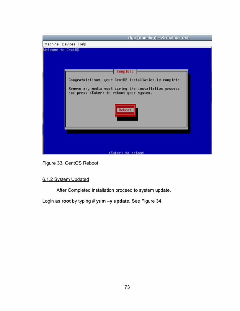
73
Figure 33. CentOS Reboot 6.1.2 System Updated
After Completed installation proceed to system update.
Login as root by typing # yum –y update. See Figure 34.

74
Figure 34. System Updating Reboot the system after update completed. See Figure 35.

75
Figure 35. System Rebooted 6.1.3 Firewall Configuration
After reboot the system, select “Firewall configuration” and press “Run Tool”
see Figure 36.

76
Figure 36. System Firewall Configuration
Select “Enabled” on Security Level and Unselect “Disabled” on SELinux and
Press “Customize”
Press OK
6.1.4 Network Configuration
Select “Network configuration” and Press “RunTool”
Select “Edit Devices” and Press “Enter”
Select “eth0” and Press “Enter”. See Figure 37.

77
Figure 37. System Network Configuration
Unselect “Use DHCP” and type the Hostname (caltemp.csusb.edu), configure:
IP, Netmask and Gateway.

78
Figure 38. System Hostname Configuration
Press “Save”. See Figure 39

79
Figure 39. System Save Configured Settings
Select “Edit DNS configuration” and “Enter”. See Figure 40.

80
Figure 40. System DNS Configuration
Enter Hostname and
Primary and Secondary DNS1: 139.182.2.1 DNS1: 139.182.2.6
and Search as csusb.edu and
Press OK
Press “Save & Quit”
Press Exit
Reboot the system as final task. See Figure 41.

81
Figure 41. CentOS Login Screen
6.1.5 Apache Server Installation
To begin the installation, download the apache http server 2.2 source
code from the Apache website (http://httpd.apache.org/download.cgi).
To unzip the downloaded file, go to the directory location and type:
# cp –p httpd-2.2.17.tar.gz /usr/local/src/
# cd /usr/local/src
# tar xvzf httpd-2.2.17.tar.gz

82
After the files are unzipped, proceed with the formal installation by
changing to the local directory as follows:
# cp –p httpd-2.2.17.tar.gz /usr/local/src/
# cd /usr/local/src
# tar xvzf httpd-2.2.17.tar.gz
To make sure the installation goes successful in its configuration type:
# /usr/local/apache/bin/apachectl configtest
Startup apache at the first time by typing:
# /usr/local/apache/bin/apachectl start
Before testing the server, check if the IP address is displayed correctly by
typing the following command as a root:
# /sbin/ifconfig
For clearer details see Figure 42.

83
Figure 42. Apache Server IP Verification Screen

84
To verify the IP of the Server, open a browser and type the IP address
139.182.237.58 into the address bar and click <enter>. You will be able to see
the “hello” text which means the page works. See Figure 43.
Figure 43. Apache Server Test Successfully Works
6.1.6 MySQL Installation
For the Web-Based Temperature Monitoring System for the College of
Arts and Letters project, I used MySQL for the same reasons I used CentOS. It is
open source and is highly reliable. It is the widely used software for data storage.
To start installing MySQL, download my MySQL from the website. I used
http://dev.mysql.com/downloads/mirrors.html. Change the current directory to:
$cd /usr/local/
When the files were extracted, they were placed in the /tmp directory, so
the command to unzip is:
# gzip –dc /tmp/mysql–5.1.69-pc-linux-gnu-i686.tar.gz | tar –xvf

85
After installation, I needed to change the ownership of all MySQL files,
and to run MySQL server service.
To change the ownership, type the following commands:
# cd /usr/local/
# chown –R mysql mysql -5.1.69-pc-linux-gnu-i686 mysql
# chgrp –R root mysql-5.1.69-pc-linux-gnu-i686 mysql
The MySQL database consists of two sample databases named ‘test’ which the
internal database uses to keep track of users and their permissions and ‘mysql’
database. See Table 3 (Server Databases).
To ensure that MySQL can run properly, we need to interact directly with
these databases, so this means that the first time login has to be as a new mysql
user (this is only the first time). As follows:
# su mysql
# cd mysql
# scripts/mysql_install_db
$ exit
Now, we continue to start MySQL application, as follows:
# /usr/local/mysql/support-files/mysql.server start
By typing mysql in the screen we can test if it downloaded successfully or not.
See Figure 24.
To login into MySQL, type:

86
$ mysql –u <username> –p
By entering the correct credentials, we can successfully log in to the MySQL
database. See Figure 44.
Figure 44. MySQL Login Screen

87
6.1.7 PHP Installation
PHP is an open source web script language that is widely used in the
construction of dynamic webpages.
For PHP installation, a terminal window is opened and the following
commands entered:
$ sudo apt-get install php5 libapache2—mod-php5.3.3
It is important to add an index.php file to the beginning of the index file.
index.php file acts like a homepage that uses a common menu to save time
when I add new pages to the website.
Restart the server as a final task. See Figure 45.
After the PHP installation process is finished, you will be able to use the
application.

88
Figure 45. PHP Version Verification Screen
6.1.8 jQuery Libraries
jQuery Libraries runs inside the browser to display temperature graphs
and retrieve data from the webserver.
I located the jQuery libraries under /var/www/html/monitor/js/ directory.
See Figure 46.

89
Figure 46. jQuery JavaScript Libraries
6.2 Server Host Names
I had to modify some of the default environment variables in the Linux
system and host files on the Apache server configuration directory in order to
correctly map to the website used for the Web-Based Temperature Monitoring
System for the College of Arts and Letters.
6.2.1 Caltemp.csusb.edu and Caltempsensor1.csusb.edu
To see the hosts file open a terminal window and type: $ vi /etc/ hosts
then click <enter>

90
You can see the localhost.localdomain, caltemp.csusb.edu, with its IP
address 192.168.1.1, and caltempsensor1.csusb.edu with its IP address
192.168.1.80. See Figure 47 and 48.
Figure 47. Linux Host Names Configuration
The temperature of 75.10 (Fahrenheit) that Figure 48, is the current server
room temperature measured by the Arduino sensor. We can open the browser
and type the caltempsensor1.csusb.edu host name into the address bar to view
the current temperature inside the server room.

91
Figure 48. Accessing Temperature Data Directly

92
6.3 Backup and Restore
A backup is very important. For this project, I will be implementing two
backups – one for MySQL database and one for the PHP, C++ and Java Script
program files. For the MySQL database backup, I utilized the one used by the
system. And for the program files, I used the second drive storage which is
attached to the system.
6.3.1 System Backup
On the system backup, I need to back up all of the files, including all
subdirectories that are located in the directory /var/www/html/monitor. In order to
do it, we need to compress the program to a “tar” file. The following command is
used to back up the entire directory:
tar czf monitor_backup.tar.gz var/www/html/monitor/
6.3.2 Database Backup
For database data backup, I implemented the tool that comes with the
original MySQL software, which is mysqldump. Open a terminal and type the
following command:
mysqldump monitor –u root –p > mysqldum.sql
Note: For the above command, you need to know the root password.

93
6.3.3. System Restore
System restore is an easy task when you have backed up the system
periodically. To restore, extract the backup file by using the following command:
tar –xzvf monitor_backup /
Enter the following command to restore the extracted files into the proper
directory system: tar –xzvf monitor_backup / command.
6.3.4 Database Restore
To restore the database, enter the following command into the terminal:
mysqldump monitor –u root –p < mysqldum.sql
Note: For the above command you need to know the root password.

94
CHAPTER SEVEN
CONCLUSION AND FUTURE DIRECTIONS
7.1 Conclusion
The Web-Based Temperature Monitoring System for the College of Arts
and Letters helps users keep track of the College of Arts & Letters’ server room
temperature from a remote location. The project’s mission is to inform system
administrators via email/text if a critical temperature has being reached inside the
server room, as well as provide a method for displaying the current server room
temperature.
This system will improve the productivity of system administrators by
providing remote access to temperature information and will reduce the likelihood
of costly hardware failures caused by heat.
The system can be accessed via the Internet through various browsers,
including Google Chrome and Mozilla Firefox. The user must have an account to
access the system.
The Web-Based Temperature Monitoring System for the College of Arts
and Letters has been designed and implemented with highly effective
contemporary hardware and software technologies, whose primary function is to
make it flexible for future enhancements and improvements.

95
REFERENCES
1. A. Goswami, T. Bezboruah and K.C. Sarma “Design of an Embedded System for Monitoring and Controlling Temperature and Light” IJEER Volume 1 Number 1 (2009) pp. 27–36
2. "Arduino - HomePage." Arduino - HomePage. N.p., n.d. Web. 17 July
2012. http://www.arduino.cc/
3. B. Yan and D. Lee “Application of RFID in Cold Chain Temperature Monitoring System”. ISECS International Colloquium on Computing, Communication, Control, and Management, 2009.
4. P. Corke, T. Wark, J. Raja, H. Wen, P. Valencia, and D. Moore.
"Environmental Wireless Sensor Networks." Proceedings of the IEEE 98.11 (2010): 1903-917
5. D. Culler, D. Estrin, M. Srivastava, Guest Editors' Introduction:
Overview of Sensor Networks, Computer 37(8): 41-49, 2004.
6. “Electrical 4 you - Online Electrical Engineering Study Site.” Types of resistor Carbon Composition and Wire Wound Resistor. N.p., n.d. Web. Sept. 2014. http://www.electrical4u.com/types-of-resistor-carbon-composition-and-wire-wound-resistor/
7. L. Welling and L. Thomson, PHP and MySQL Web Development.
Indianapolis, IN: SAMS, 2001.
8. M. Kassim, M.N. Ismail, and C.K.H. Che Ku Yahaya. “Web Based Temperature Monitoring System”. Facultuy of Electrical Engineering, Universiti Teknology, MARA (UiTM), Malaysia Department of MIIT, University of Kuala Lumpur (UNiKL), Malaysia
9. S.L.Y. Youling, X. Weisheng, “Design of Remote Real-Time
Temperature Monitoring System”. The Eighth International Conference on Electronic Measurement and Instruments ICEMI Proceeding 2007.
10. “Ussensor – Online U.S.SENSOR corp. Innovative Temperature Sensing Solution.” What is a thermistor? N.p., n.d. Mon. Nov. 2014. http://www.ussensor.com/technical-info/what-is-a-thermistor