a vision beyond the advanced virgo project
TRANSCRIPT
A Vision Beyond the Advanced Virgo Project
VIR-0136A-16
The VIRGO collaborationSeptember 2016
1
Contents
1 Introduction 3
2 Advanced Virgo and beyond 42.1 The future of Advanced Virgo . . . . . . . . . . . . . . . . . . . . 52.2 From Advanced Virgo to Einstein Telescope . . . . . . . . . . . . 7
3 Newtonian noise cancellation 93.1 Introduction . . . . . . . . . . . . . . . . . . . . . . . . . . . . . . 93.2 Part 1: Site characterisation and noise modelling . . . . . . . . . 93.3 Part 2: Coherent detection of Newtonian noise . . . . . . . . . . 103.4 Part 3: Development of Newtonian-noise cancellation system . . 113.5 Timeline . . . . . . . . . . . . . . . . . . . . . . . . . . . . . . . . 12
4 Lowering the thermal noise 144.1 Scientific case . . . . . . . . . . . . . . . . . . . . . . . . . . . . . 144.2 Increase of the beam profile . . . . . . . . . . . . . . . . . . . . . 15
4.2.1 Increasing the mirror substrate size . . . . . . . . . . . . . 154.2.2 Coating development on large mirrors . . . . . . . . . . . 16
4.3 New coating materials . . . . . . . . . . . . . . . . . . . . . . . . 17
5 Larger beams and thermal noise limit 205.1 Cost and man power . . . . . . . . . . . . . . . . . . . . . . . . . 21
6 Squeezing 226.1 Introduction . . . . . . . . . . . . . . . . . . . . . . . . . . . . . . 226.2 Implementation Plan . . . . . . . . . . . . . . . . . . . . . . . . . 236.3 Cost Estimate . . . . . . . . . . . . . . . . . . . . . . . . . . . . . 23
7 The improvement of the detector robustness 257.1 Anthropogenic noise reduction . . . . . . . . . . . . . . . . . . . 257.2 Low frequency robustness . . . . . . . . . . . . . . . . . . . . . . 257.3 The optical stability of the recycling cavities: the long cavity
solution . . . . . . . . . . . . . . . . . . . . . . . . . . . . . . . . 277.4 The upgrades of thermal compensation system . . . . . . . . . . 28
8 Extending the arm length of Virgo 308.1 Motivation . . . . . . . . . . . . . . . . . . . . . . . . . . . . . . 308.2 Discussion . . . . . . . . . . . . . . . . . . . . . . . . . . . . . . . 308.3 Implementation Plan . . . . . . . . . . . . . . . . . . . . . . . . . 318.4 Cost and man power . . . . . . . . . . . . . . . . . . . . . . . . . 32
9 Conclusion 33
2
1 Introduction
The scope of this document is to trace a path of the evolution of AdvancedVirgo toward the third generation of detectors. The sensitivity of AdvancedVirgo can be improved further by adding new sub-systems as a vacuum squeezer,and/or increasing further the mirror dimensions and the quality of their coating.Moreover, after the first detection it becomes more and more important toincrease the reliability of the international network for increasing the overallobservational time. This implies to improve the robustness of each detector . Inthis document our goal is mainly to give a coherent picture of the main actionsto be pursued in the short and middle terms for achieving these goals.
Then, we will try to draw a potential scenario for the longer term improvements.In this context, for completeness, we looked also at hypothetic changes of theVirgo infrastructure even to the increase of the Virgo arm length.
The major detectors currently operative are enhanced versions of the first gen-eration (Virgo+ and eLIGO), with higher laser power and some technologicalimprovements. They are based on technologies currently available, sometimestested in reduced scale prototypes and then implemented in full scale. Despitethe big progress made, the current detectors are not fully exploiting the poten-tiality if the infrastructures hosting them.Therefore, there is room for furtherenhancement of the 2nd generation targets. The R&D carried out within theGW community in the last years already makes possible to walk steps forward:for instance, the technology to produce and inject squeezed states in large in-terferometers has been already demonstrated and a relevant progress has beendone on the way to realise a frequency dependent squeezing. We analyse in thefollowing sections the open options for the AdV enhancement and highlight themost likely path that Virgo plans to follow.
The starting point of the following discussion is the final design sensitivity curveof Advanced Virgo.
The figure shows clearly that in oder to improve the sensitivity above 10 Hz, twomain actions must be pursued: the reduction of the mirror thermal noise andthe quantum noise. The last requires an experimental effort for implementinga vacuum squeezer, while for the mirror thermal noise the multiple approach ofimproving the dissipations associated to the mirror coating and enlarging thebeams impinging on the mirrors Below 10 Hz the curve reported in the figure 1,which contributes mainly to the final sensitivity is the Newtonian Noise followedby the suspension thermal noise. However, the experience learned with Virgoand Virgo+ tells us that in this frequency range other noise sources, with nostationary characteristics and difficult to model, can contribute. We will callthem technical noise sources and we will discuss how to deal with these limitationin the section devoted the improvements of the detector robustness.
3
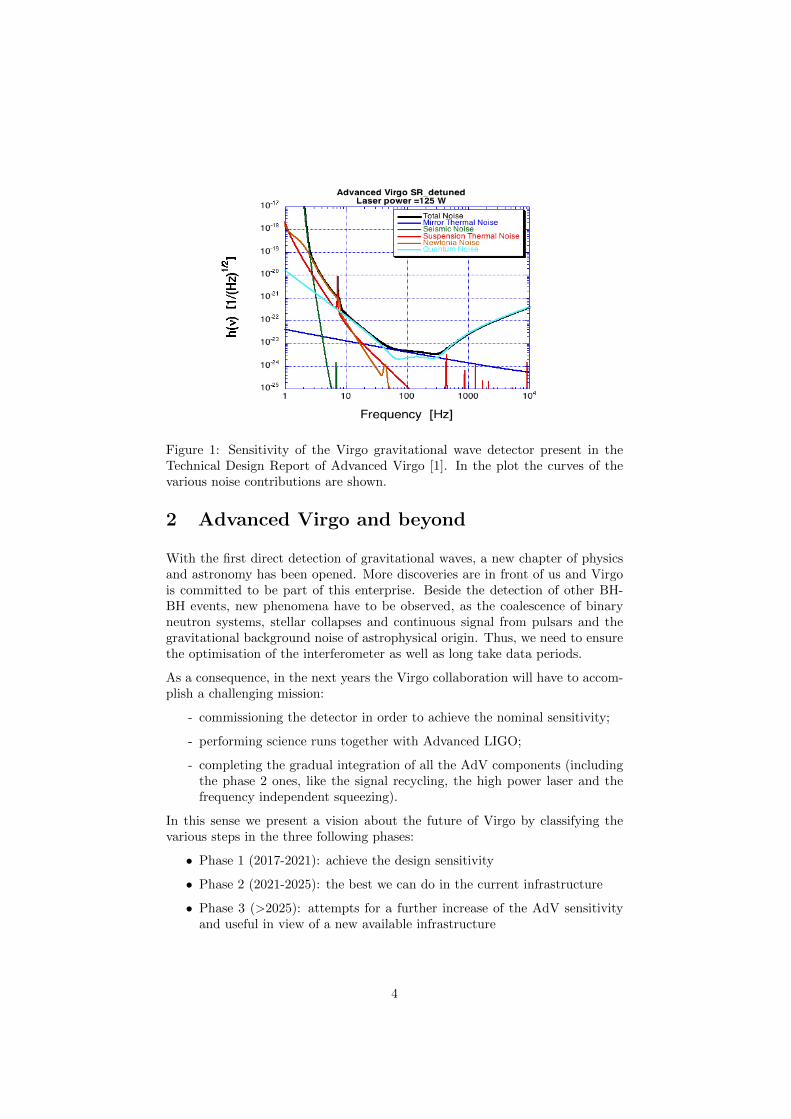
Figure 1: Sensitivity of the Virgo gravitational wave detector present in theTechnical Design Report of Advanced Virgo [1]. In the plot the curves of thevarious noise contributions are shown.
2 Advanced Virgo and beyond
With the first direct detection of gravitational waves, a new chapter of physicsand astronomy has been opened. More discoveries are in front of us and Virgois committed to be part of this enterprise. Beside the detection of other BH-BH events, new phenomena have to be observed, as the coalescence of binaryneutron systems, stellar collapses and continuous signal from pulsars and thegravitational background noise of astrophysical origin. Thus, we need to ensurethe optimisation of the interferometer as well as long take data periods.
As a consequence, in the next years the Virgo collaboration will have to accom-plish a challenging mission:
- commissioning the detector in order to achieve the nominal sensitivity;
- performing science runs together with Advanced LIGO;
- completing the gradual integration of all the AdV components (includingthe phase 2 ones, like the signal recycling, the high power laser and thefrequency independent squeezing).
In this sense we present a vision about the future of Virgo by classifying thevarious steps in the three following phases:
• Phase 1 (2017-2021): achieve the design sensitivity
• Phase 2 (2021-2025): the best we can do in the current infrastructure
• Phase 3 (>2025): attempts for a further increase of the AdV sensitivityand useful in view of a new available infrastructure
4
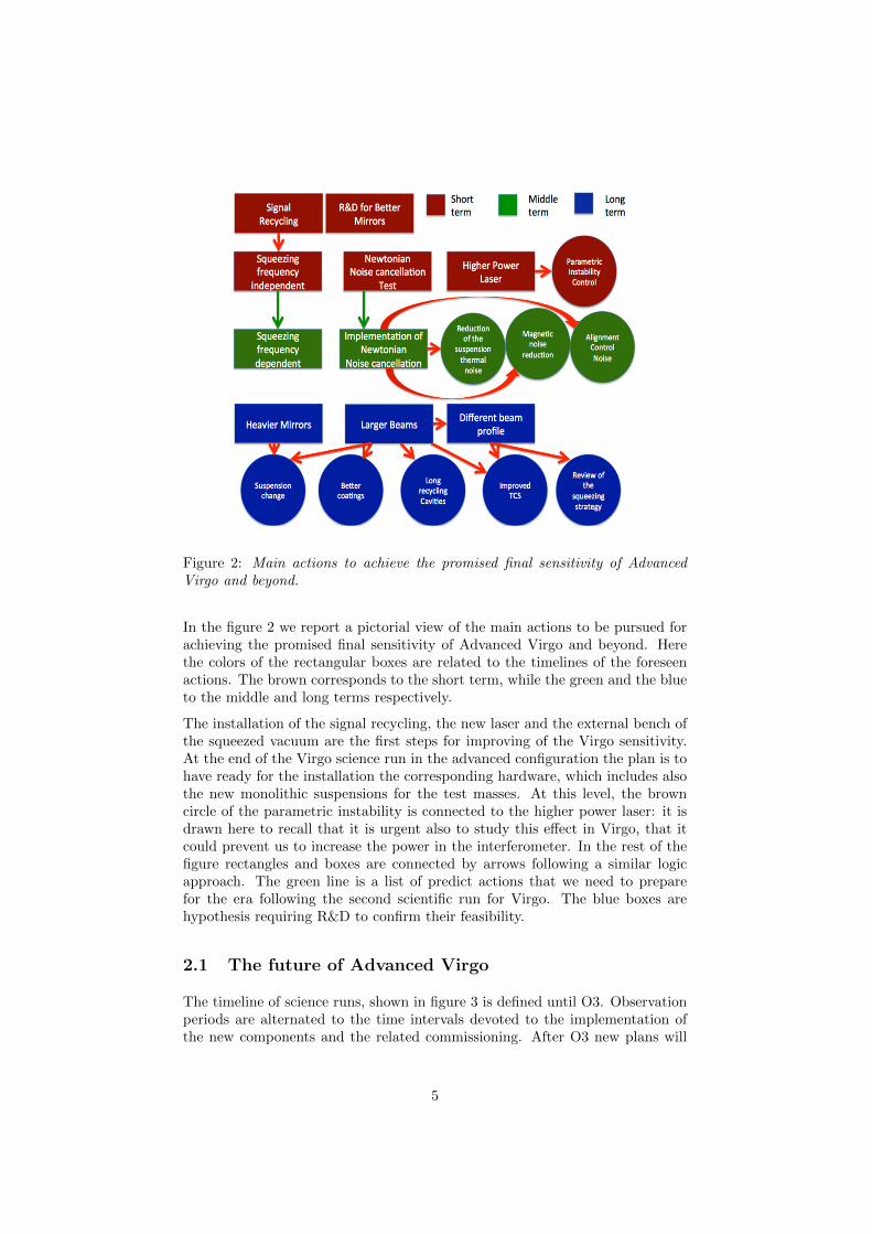
Figure 2: Main actions to achieve the promised final sensitivity of AdvancedVirgo and beyond.
In the figure 2 we report a pictorial view of the main actions to be pursued forachieving the promised final sensitivity of Advanced Virgo and beyond. Herethe colors of the rectangular boxes are related to the timelines of the foreseenactions. The brown corresponds to the short term, while the green and the blueto the middle and long terms respectively.
The installation of the signal recycling, the new laser and the external bench ofthe squeezed vacuum are the first steps for improving of the Virgo sensitivity.At the end of the Virgo science run in the advanced configuration the plan is tohave ready for the installation the corresponding hardware, which includes alsothe new monolithic suspensions for the test masses. At this level, the browncircle of the parametric instability is connected to the higher power laser: it isdrawn here to recall that it is urgent also to study this effect in Virgo, that itcould prevent us to increase the power in the interferometer. In the rest of thefigure rectangles and boxes are connected by arrows following a similar logicapproach. The green line is a list of predict actions that we need to preparefor the era following the second scientific run for Virgo. The blue boxes arehypothesis requiring R&D to confirm their feasibility.
2.1 The future of Advanced Virgo
The timeline of science runs, shown in figure 3 is defined until O3. Observationperiods are alternated to the time intervals devoted to the implementation ofthe new components and the related commissioning. After O3 new plans will
5
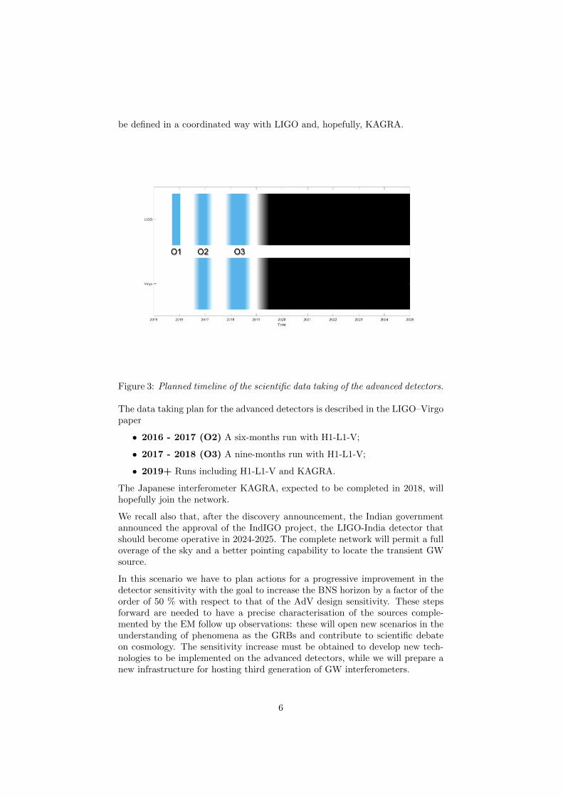
be defined in a coordinated way with LIGO and, hopefully, KAGRA.
Figure 3: Planned timeline of the scientific data taking of the advanced detectors.
The data taking plan for the advanced detectors is described in the LIGO–Virgopaper
• 2016 - 2017 (O2) A six-months run with H1-L1-V;
• 2017 - 2018 (O3) A nine-months run with H1-L1-V;
• 2019+ Runs including H1-L1-V and KAGRA.
The Japanese interferometer KAGRA, expected to be completed in 2018, willhopefully join the network.
We recall also that, after the discovery announcement, the Indian governmentannounced the approval of the IndIGO project, the LIGO-India detector thatshould become operative in 2024-2025. The complete network will permit a fulloverage of the sky and a better pointing capability to locate the transient GWsource.
In this scenario we have to plan actions for a progressive improvement in thedetector sensitivity with the goal to increase the BNS horizon by a factor of theorder of 50 % with respect to that of the AdV design sensitivity. These stepsforward are needed to have a precise characterisation of the sources comple-mented by the EM follow up observations: these will open new scenarios in theunderstanding of phenomena as the GRBs and contribute to scientific debateon cosmology. The sensitivity increase must be obtained to develop new tech-nologies to be implemented on the advanced detectors, while we will prepare anew infrastructure for hosting third generation of GW interferometers.
6
2.2 From Advanced Virgo to Einstein Telescope
The roadmap from the 2nd to the 3rd generation of GW observatories is basedon the following key points:
• Achieving the nominal sensitivity minimising the down–times due to heavyinstallations and performing a long data taking at the beginning of thenext decade;
• Enhancing the sensitivity of the Advanced detectors by adopting new tech-nologies as the frequency dependent squeezing, larger and better coatedmirrors, newtonian noise subtraction, . . . to fully exploit the available in-frastructure;
• Starting the realisation of a 3rd generation infrastructure, the EinsteinTelescope.
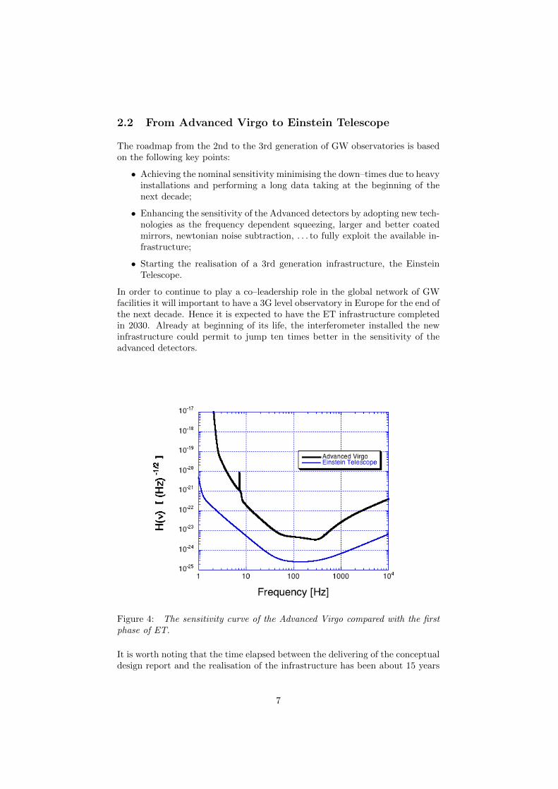
In order to continue to play a co–leadership role in the global network of GWfacilities it will important to have a 3G level observatory in Europe for the end ofthe next decade. Hence it is expected to have the ET infrastructure completedin 2030. Already at beginning of its life, the interferometer installed the newinfrastructure could permit to jump ten times better in the sensitivity of theadvanced detectors.
Figure 4: The sensitivity curve of the Advanced Virgo compared with the firstphase of ET.
It is worth noting that the time elapsed between the delivering of the conceptualdesign report and the realisation of the infrastructure has been about 15 years
7
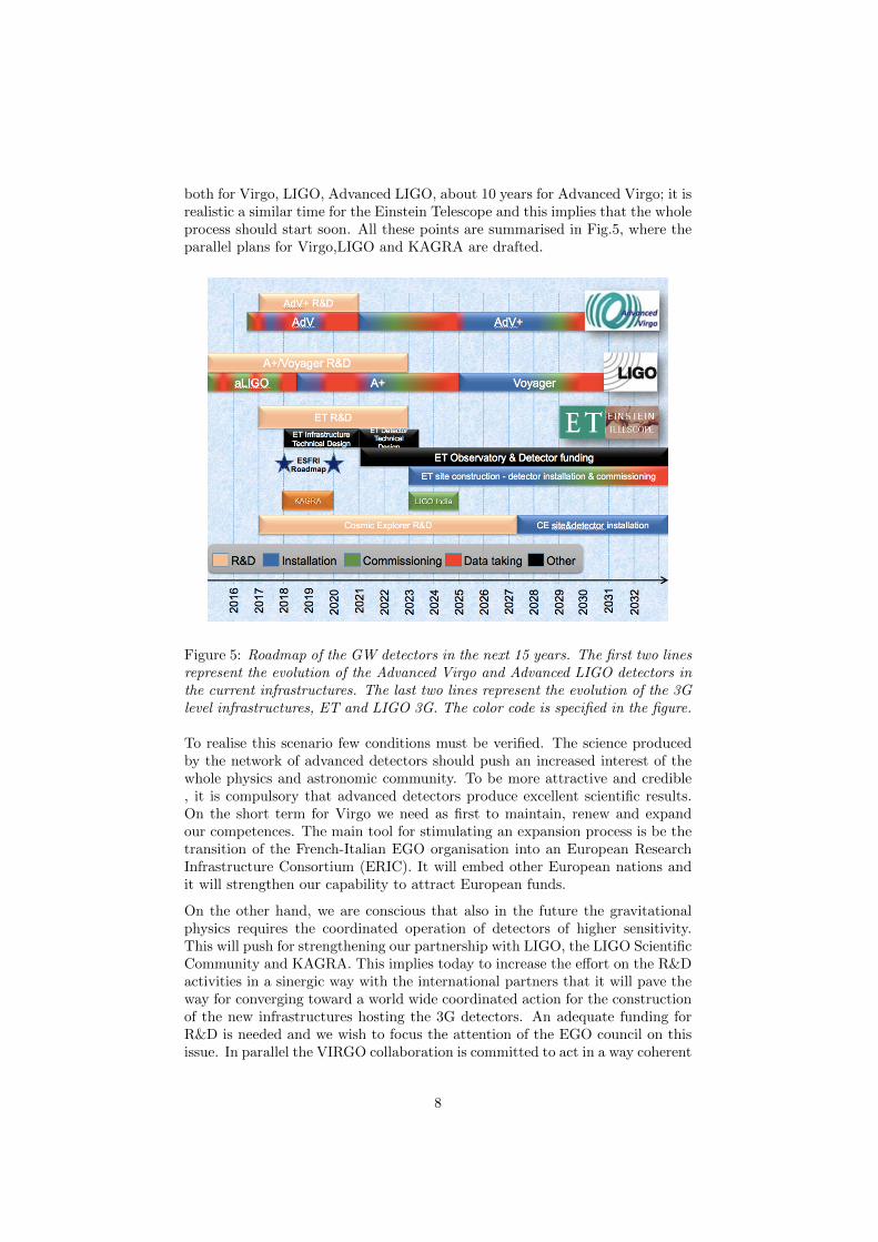
both for Virgo, LIGO, Advanced LIGO, about 10 years for Advanced Virgo; it isrealistic a similar time for the Einstein Telescope and this implies that the wholeprocess should start soon. All these points are summarised in Fig.5, where theparallel plans for Virgo,LIGO and KAGRA are drafted.
Figure 5: Roadmap of the GW detectors in the next 15 years. The first two linesrepresent the evolution of the Advanced Virgo and Advanced LIGO detectors inthe current infrastructures. The last two lines represent the evolution of the 3Glevel infrastructures, ET and LIGO 3G. The color code is specified in the figure.
To realise this scenario few conditions must be verified. The science producedby the network of advanced detectors should push an increased interest of thewhole physics and astronomic community. To be more attractive and credible, it is compulsory that advanced detectors produce excellent scientific results.On the short term for Virgo we need as first to maintain, renew and expandour competences. The main tool for stimulating an expansion process is be thetransition of the French-Italian EGO organisation into an European ResearchInfrastructure Consortium (ERIC). It will embed other European nations andit will strengthen our capability to attract European funds.
On the other hand, we are conscious that also in the future the gravitationalphysics requires the coordinated operation of detectors of higher sensitivity.This will push for strengthening our partnership with LIGO, the LIGO ScientificCommunity and KAGRA. This implies today to increase the effort on the R&Dactivities in a sinergic way with the international partners that it will pave theway for converging toward a world wide coordinated action for the constructionof the new infrastructures hosting the 3G detectors. An adequate funding forR&D is needed and we wish to focus the attention of the EGO council on thisissue. In parallel the VIRGO collaboration is committed to act in a way coherent
8

with the picture reported in this document and take advantage of additionalsupport got at national and international level.
Timing:
Table 1: Timeline for ta 3G infrastructure and detectorAction Timeline
Infrastructure design ESFRI roadmap timelineSite selection 2021-2022
Construction starts 2023Detector design end-2022 /mid-2023
First data of the first 3G ITF 2030
3 The Newtonian Noise Cancellation
3.1 Introduction
Newtonian noise (NN) is predicted to become a sensitivity limiting noise sourcein Advanced Virgo at frequencies below 20 Hz. Potentially relevant sources ofgravity perturbations include seismic waves, atmospheric perturbations, and vi-brating structures near test masses. Coherent noise cancellation is currentlybeing investigated as most promising noise-mitigation technique with minimalimpact on the infrastructure of the existing detectors. The cancellation schemeenvisions the deployment of environmental sensors near all test masses of theGW detectors to retrieve information about mass-density fluctuations, whichthen serves to produce a coherent estimate of NN. The effectiveness of thisscheme was demonstrated in numerical simulations based on realistic composi-tions of the seismic field, and has been applied successfully in the past to cancelother types of noise in GW detectors. Site characterisation, analytical stud-ies, and numerical simulations have all been identified as quintessential for thedevelopment of NN cancellation systems. The goal of this project is to worktowards NN suppression by more than a factor 10 over the next 5 to 10 years.
3.2 Part 1: Site characterisation and noise modelling
A detailed characterisation of the Virgo site needs to be carried out with initialfocus on understanding the seismic field in terms of its spectra and two-pointspatial correlation. These quantities are fundamental to the design of the seis-mic arrays for the purpose of noise cancellation. With improving cancellationperformance, other contributions to NN will become relevant, which calls formore detailed site characterization with respect to atmospheric perturbations,and vibration of detector infrastructure. The various site characterization tasks,ordered according to when they are expected to become relevant, are the fol-lowing:
9
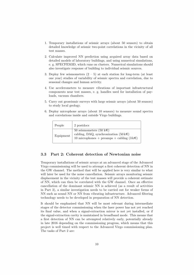
1. Temporary installations of seismic arrays (about 50 sensors) to obtaindetailed knowledge of seismic two-point correlations in the vicinity of alltest masses.
2. Calculate improved NN prediction using acquired array data based ondetailed models of laboratory buildings, and using numerical simulations,e. g. SPECFEM3D, which runs on clusters. Numerical simulations shouldalso investigate response of building to individual seismic sources.
3. Deploy few seismometers (2 – 5) at each station for long-term (at leastone year) studies of variability of seismic spectra and correlation, due toseasonal changes and human activity.
4. Use accelerometers to measure vibrations of important infrastructuralcomponents near test masses, e. g. handles used for installation of pay-loads, vacuum chambers.
5. Carry out geoseismic surveys with large seismic arrays (about 50 sensors)to study local geology.
6. Deploy microphone arrays (about 10 sensors) to measure sound spectraand correlations inside and outside Virgo buildings.
People 2 postdocs
Equipment
50 seismometers (50 k€)cabling, DAQ, synchronization (50 k€)10 microphones + preamps + cabling (3 k€)
3.3 Part 2: Coherent detection of Newtonian noise
Temporary installations of seismic arrays at an advanced stage of the AdvancedVirgo commissioning will be used to attempt a first coherent detection of NN inthe GW channel. The method that will be applied here is very similar to whatwill later be used for the noise cancellation. Seismic arrays monitoring seismicdisplacement in the vicinity of the test masses will provide a coherent estimateof NN, which can then be correlated with the GW channel. Once an effectivecancellation of the dominant seismic NN is achieved (as a result of activitiesin Part 3), a similar investigation needs to be carried out for weaker forms ofNN such as sound NN or NN from vibrating infrastructure. Advanced filteringtechnology needs to be developed in preparation of NN detection.
It should be emphasised that NN will be most relevant during intermediatestages of the detector commissioning when the laser power has not yet reachedits final value, and when a signal-extraction mirror is not yet installed, or ifthe signal-extraction cavity is maintained in broadband mode. This means thata first detection of NN can be attempted relatively early, potentially alreadyin late 2016 depending on the commissioning progress, which means that thisproject is well timed with respect to the Advanced Virgo commissioning plan.The tasks of Part 2 are:
10
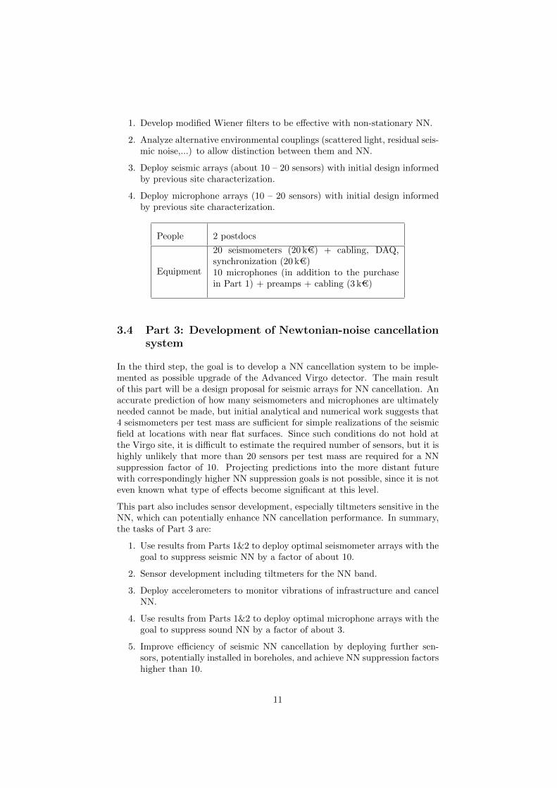
1. Develop modified Wiener filters to be effective with non-stationary NN.
2. Analyze alternative environmental couplings (scattered light, residual seis-mic noise,...) to allow distinction between them and NN.
3. Deploy seismic arrays (about 10 – 20 sensors) with initial design informedby previous site characterization.
4. Deploy microphone arrays (10 – 20 sensors) with initial design informedby previous site characterization.
People 2 postdocs
Equipment
20 seismometers (20 k€) + cabling, DAQ,synchronization (20 k€)10 microphones (in addition to the purchasein Part 1) + preamps + cabling (3 k€)
3.4 Part 3: Development of Newtonian-noise cancellationsystem
In the third step, the goal is to develop a NN cancellation system to be imple-mented as possible upgrade of the Advanced Virgo detector. The main resultof this part will be a design proposal for seismic arrays for NN cancellation. Anaccurate prediction of how many seismometers and microphones are ultimatelyneeded cannot be made, but initial analytical and numerical work suggests that4 seismometers per test mass are sufficient for simple realizations of the seismicfield at locations with near flat surfaces. Since such conditions do not hold atthe Virgo site, it is difficult to estimate the required number of sensors, but it ishighly unlikely that more than 20 sensors per test mass are required for a NNsuppression factor of 10. Projecting predictions into the more distant futurewith correspondingly higher NN suppression goals is not possible, since it is noteven known what type of effects become significant at this level.
This part also includes sensor development, especially tiltmeters sensitive in theNN, which can potentially enhance NN cancellation performance. In summary,the tasks of Part 3 are:
1. Use results from Parts 1&2 to deploy optimal seismometer arrays with thegoal to suppress seismic NN by a factor of about 10.
2. Sensor development including tiltmeters for the NN band.
3. Deploy accelerometers to monitor vibrations of infrastructure and cancelNN.
4. Use results from Parts 1&2 to deploy optimal microphone arrays with thegoal to suppress sound NN by a factor of about 3.
5. Improve efficiency of seismic NN cancellation by deploying further sen-sors, potentially installed in boreholes, and achieve NN suppression factorshigher than 10.
11
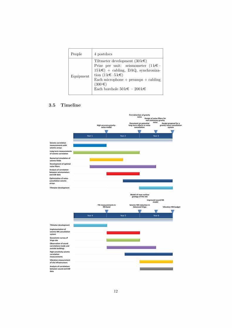
People 4 postdocs
Equipment
Tiltmeter development (30 k€)Prize per unit: seismometer (1 k€ –15 k€) + cabling, DAQ, synchroniza-tion (1 k€ –5 k€)Each microphone + preamps + cabling(300 €)Each borehole 50 k€ – 200 k€
3.5 Timeline
Year 1 Year 2 Year 3
Design proposal for a gravity-noise cancellation
system
Design of noise filters for non-stationary gravity
noise Document on potential long-term effects in noise
cancellation
First detection of gravity noise
High-accuracy gravity-noise model
Seismic correlation measurements with seismic arrays
Long-term measurements of seismic correlation
Numerical simulation of seismic fields
Development of optimal noise filters
Analysis of correlation between seismometers and GW data
Optimization of noise-cancellation seismic arrays
Tiltmeter development
Year 4 Year 5 Year 6
Improved sound NN model
Seismic NN reduction in Advanced Virgo
Model of near-surface geology of the site
Tilt measurements in NN band
Geoseismic survey of Virgo site
Observation of sound correlations inside and outside buildings
Analysis of correlations between sound and GW data
Implementation of seismic NN cancellation system
Tiltmeter development
Vibration measurement of site infrastructure
High-sensitivity seismic correlation measurements
Vibration NN budget
12
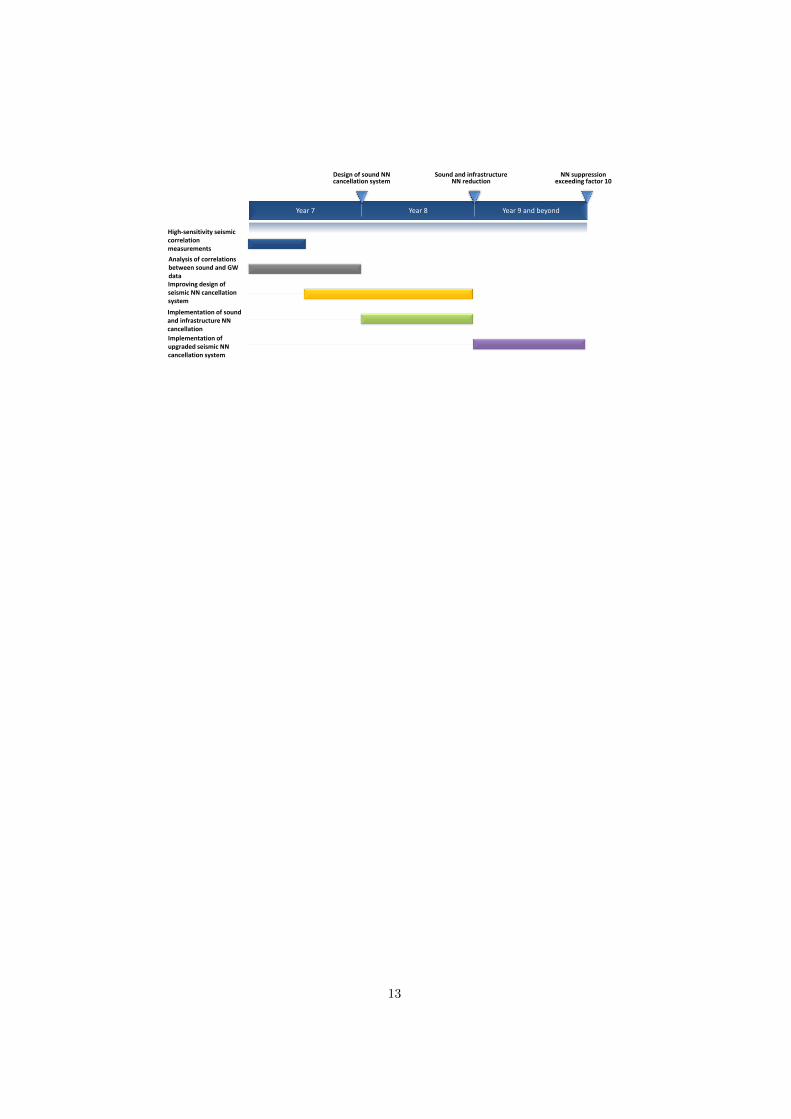
Year 7 Year 8 Year 9 and beyond
NN suppression exceeding factor 10
Sound and infrastructure NN reduction
Design of sound NN cancellation system
Analysis of correlations between sound and GW data Improving design of seismic NN cancellation system
Implementation of upgraded seismic NN cancellation system
High-sensitivity seismic correlation measurements
Implementation of sound and infrastructure NN cancellation
13
4 Lowering the thermal noise
4.1 Scientific case
In the frequency band were Advanced Virgo is more sensitive, the dominantlimiting noise is the thermal noise of coatings. Any reduction factor of coatingthermal noise level will determine an increment of the same factor either of themaximum detection distance or of the signal-to-noise-ratio. Moreover, reducingthe thermal noise will allow the interferometer to be quantum limited over mostof its frequencies, enabling the fully benefit of using squeezed light.
The dependence of coating thermal noise level on the different detector param-eters will be given below and in the next sections the upgrades plan will beoutlined.
It has been demonstrated experimentally that thermal noise spectral densitySxx in coatings is related to the different parameters of the laser beam andmirror by the following expression:
Scoatxx = 2 kB T ·
1− σs√π3 wYs
· φefff· C2
FTM (1)
where kB is the Boltzmann constant, T is the temperature, σs and Ys thePoisson ratio and the Young’s modulus of the substrate, w the laser spot sizeon the mirror (w is the radius at which the field amplitude drops down to 1/e,f the frequency, C2
FTM is a correction term that takes into account the finitedimensions of the substrate and the effective loss angle of the material φeff is
φeff =h√π w
(YsY⊥
φ⊥ +Y‖
Ysφ‖
)(2)
where h and φ is the coating thickness and loss angle respectively. The symbols⊥ and ‖ indicate the directions perpendicular and orthogonal with respect tothe surface of the coatings.
At room temperature there is not any other material for the mirror substratelike Suprasil®(a special synthetic fused silica made by Heraus GmbH) in termsof absorption, homogeneity and stress release. Therefore for all the room tem-perature upgrades of Advanced Virgo the substrate material will remain thesame.
The only possible reduction of coating thermal noise has to come from the in-crease of the beam radius w and the reduction of mechanical loss angle φ.
The beam radius is the parameter that gives the strongest dependence of ther-mal noise above of all the others. The beam size on the mirrors is limited bythe maximum allowable clipping losses and by the stability parameter g of thecavities.Changing the optical mode from simple Gaussian into one of the higher modes
14

like the Laguerre-Gauss 33 (LG33) give an increment of a factor 1.7 of the effec-tive beam size w but at the same time the compatibility of higher order modeswith squeezing of light has to be demonstrated yet. For Advanced Virgo threetypes of upgrades are possible having different benefit and impact on the detec-tor as explained synthetically in the next table.
Upgrade Benefit ChangesNo change on substrate di-mensions
Thermal noise reductionrelies on new coating ma-terial
Cavity mirrors + inputand output optics
Little increase of beamsizeLarger mirrors but samemass
Significant reduction ofthermal noise based onlarger w and lower φ
as above + beam splitterand payload design
Larger mirrors with sameaspect ratio
Largest reduction of ther-mal noise
as above + upper suspen-sions design
Production of coatings for larger mirrors and development of a new low lossmaterials are the two R&D programs necessary for the upgrades od AdvancedVirgo. A description of these two programs, their implementation plan and costwill be given in the next sections.
4.2 Increase of the beam profile
Increasing the beam profile could be done in two complimentary ways: increas-ing the diameter of the mirror substrate and using higher-order mode. Anotheradvantage of using larger beams is the reduction of the thermal lensing magni-tude, thanks to the reduction in the power density.
4.2.1 Increasing the mirror substrate size
One solution to have larger beams on the arm cavity mirrors is simply to havelarger diameter substrates to keep the clipping losses at a negligeable value (inthe order of few ppm). So what could be the maximum diameter for the mirror? To limit the risk and the development time, one can choose to have the armcavity mirrors of the same size as the current Advanced Virgo beamsplitter,the largest optic of the interferometer. The current beamsplitter is 550 mm indiameter, 65 mm thick and weighting 40 kg (the same weight as the actual testmasses). We already know that such piece could be handled, cleaned, coatedand caracterized at LMA (see section 4.2.2). Moreover, a suspension for sucha large piece has already been developed and installed, albeit not a monolithicone.
So using a 550 mm diameter miroir, one can expect a possible increase of 60% ofthe size of the beam on the mirrors, compared to Advanced Virgo. That means
15
a reduction of a factor 1.6 for the amplitude of the coating thermal noise and areduction of 2.6 for the magnitude of thermal lensing. The beam radius will be80 mm on the input mirror and 95 mm on the end mirror. Since we keep thearm cavities the same length, we will be closer to the instability region with ag-factor of 0.98. That leads to more stringent specifications on the mirror radiusof curvature as well as the alignment system.
Even with a beam of 80 mm radius at the level of the input mirrors, it is possibleto keep similar size of optics (PR, POP, SR, BS and CP) in the central part ofthe interferometer at the price of higher clipping loss, and hence more light onthe baffles. For example, a beam of 80 mm passing through a 330 mm diameteroptic will loose 200 ppm of its power, this value must be compared to thecurrent 1500 ppm loss in the power recycling cavity. It should be noted that thereduction of the recycling gain due that additional loss, could be compensatedby reducing the transmission of the power recycling mirror.
It is possible to have the same beam size on the power and signal recyclingmirrors as presently, if the input mirrors could be equivalent to a converginglens by having a curved anti-reflection side. That will come to the price ofhaving no etalon effect in the input mirror, which in any case could not bepresent due to the very good anti-reflective coating which can be achieved now(AR < 100 ppm routinely achieved).
4.2.2 Coating development on large mirrors
We suppose in this section a mirror diameter larger than 40 cm. The coatingdeposition technology developed at LMA is ready to treat two mirrors at a timein planetary motion. Although the required coating uniformity is the same asthe one achieved for Advanced Virgo, an improvement of that uniformity atdistances larger than 10 cm from the mirror centre has already started.
The proposed plan is for developing the deposition technology for mirrors withdimensions twice that of Advanced Virgo mirrors, i.e. a diameter as large as70 cm, thickness 40 cm and mass of 300 kg. These dimensions are close to themaximum possible for the Grand Coater at LMA. The cleaning facility devel-oped with the fundings for Advanced Virgo is instead limited to a diameter of55 cm.
The following tasks will form the research plan that will deliver the technologyfor future upgrades of Advanced Virgo.
i) New planetary motion. A new rotary system able to hold and spin a300 kg mirror at sufficiently high speed to have the maximum uniformityon nanometric layers will be developed. The system will have a precisecontrol of deposition temperature over a wide range depending on theresults of the research on new materials.
ii) Dynamic control of sputtered material. Developed as an alternativeto the use of masks to make uniform the coating thickness, this tech-
16

nique is based on changing the geometry of the targets with respect to theion beams so that the direction of sputtered material will be controlled.This task is developed in two stages: at first there is the conception andrealization of the mechanics of the new system; later, there will be theoptimization of the different parameters. This significant change of theGran Coater will make it unavailable for any production of large mirrorsfor a considerably long time.
iii) Post deposition correction. This technique is based on applying alayer of silica after the deposition of the full stack of coatings in order tocorrect the wave front of the reflected light. The design of the coatingstack has to be conceived specifically for the possible further correction.The deposition can be realized with the robot already developed with theAdvanced Virgo fundings for the correction of the substrate or with thenew system based on the sputtering lobe control of point ii).
iv) Study of aberrations. The development of coatings for Advanced Virgohas not answered to a question: what are the wavefront aberrations thatmore than others contribute to the loss of the cavities? Apparently theordinary development on Zernike polynomial is not the most suited to thispurpose and a new base has to be found. The outcome of this activity willindicate which type of post-deposition correction is necessary to apply tothe stack.
Several new technologies for mirrors and suspensions are going to be developedfor the upgrades of Advanced Virgo. At the end of the project a demonstrator,a pathfinder, is proposed based on a mirror of 550 mm diameter.
4.3 New coating materials
The coating stack used for Advanced Virgo was made by alternating layers ofsilica (SiO2) and titania doped tantala (TiO2:Ta2O5) having mechanical lossesof (0.45±0.03)×10−4 and (2.4±0.3)×10−4 respectively as measured on mono-layers deposited on cantilevers. The stack design was optimized in order toreduce the fraction of the lossier titania doped tantala but the gain was reducedby an excess loss supposedly related to the interfaces that brought the total lossangle of the ETM HR stack at (2.3± 0.1)× 10−4, close to that of TiO2:Ta2O5.The mixing of titania and tantala gave the lowest loss angle among all the highindex materials tested at that time.
It is impossible to aim at a fixed reduction factor of coating loss angle becausethere is not yet a theory that explain the level of losses and relates it to thestructural parameters at molecular level. Most of the amorphous materials havelosses in the range 10−4 − 10−3. Recently films of amorphous silicon depositedat 400◦C have shown losses as low as 10−6 but the material is not transparentat 1064 nm.
The research plan for the development of the new materials for the future up-grades of Advanced Virgo follows.
17
i) New amorphous materials. Selection of few oxides and nitrides, opti-mization of the deposition parameters for optical and mechanical proper-ties. At first the work will be focused on the high index materials becausethey contribute the most to the overall loss of the stack.
ii) Investigation on new mixing. Following the experience with the ti-tania and tantala in this task different mixtures of high index oxides aretested with the double purpose of lowering the mechanical losses or in-creasing the crystallization temperature.
iii) Investigation on the high temperature deposition. Results pub-lished in the literature have shown that mechanical losses and absorptioncoefficient of amorphous semiconductors deposited at high temperatureare reduced more than what is achieved with a post-deposition annealingdone at the same temperature. This task aims to investigate the effect ofthe deposition temperature on oxides and nitrates.
iv) Origin of structural relaxations. The previous lines of research canbe conducted in an empirical way, finding the best set of materials anddeposition parameters that minimize the mechanical losses. In this tasklight will be shed on the structural explanation at the molecular level of theorigin of relaxations and on the different effect of mixing and temperaturedeposition. Analyzing tools are the Raman and Brillouin scattering andthe different types of X-rays diffraction.
Not only the production of samples is an important activity in terms of man-power and equipment but also and even more the characterization of samples.Optical and mechanical characterization will be assured by several of the Virgolaboratories, as long as their demand of manpower will be fulfilled. Structuralcharacterization will be done in collaboration with research groups that are nonpart of the Virgo collaboration but that have an already established collabora-tion with them.
Required resources
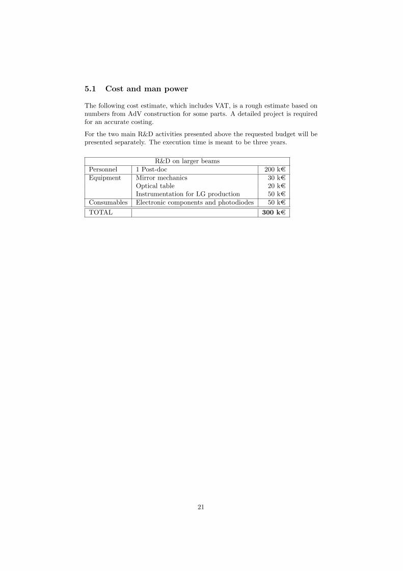
For the two main R&D activities presented above the requested budget will bepresented separately. The execution time is meant to be three years.
Coatings for large mirrorsPersonnel 1 Post-doc 200 k€Equipment Large mirror mechanics 30 k€
Temperature control 20 k€Dynamic control of scattering lobes 50 k€Metrology on large plates 20 k€
Consumables Large plates for uniformity test 50 k€Polishing of one Virgo old substrates 100 k€
Pathfinder Substrate and polishing 200 k€TOTAL 570 k€
18
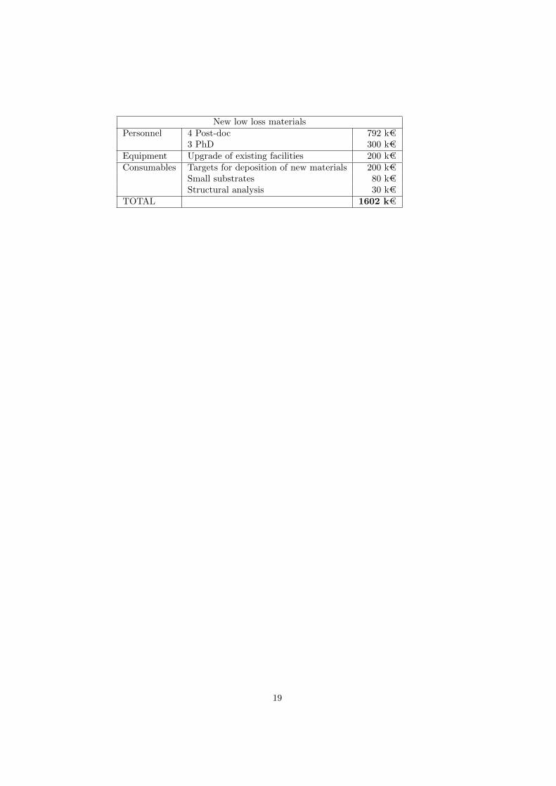
New low loss materialsPersonnel 4 Post-doc 792 k€
3 PhD 300 k€Equipment Upgrade of existing facilities 200 k€Consumables Targets for deposition of new materials 200 k€
Small substrates 80 k€Structural analysis 30 k€
TOTAL 1602 k€
19
5 Larger beams
As it was discussed in a previous section, the mirror Internal Thermal Noiseis the dominant noise source in Advanced LIGOOs maximum frequency range.Coating Thermal Noise dominates over Substrate Thermal Noise. to reducethermal noise by a factor of the order of 2. By systematically optimising thelaser intensity profile, we can decrease thermal noise compared to the use ofGaussian beams. In particular it has been proposed to use Laguerre-Gaussmodes [? ], known in the literature for their low diffraction loss. In fact, it hasbeen analytically demonstrated that the thermal noise of the mirrors can bereduced by a factor which depends on the spatial order N = 2p+ l of the LGl
p
mode resonant in the interferometer: higher N values lead to larger beams andlower thermal noise. For example, the thermal noise level could be decreased bynearly a factor of 2 by using an LG3
3 beam. Furthermore, the interferometricGW detectors are strongly affected by thermal issues, caused by laser powerabsorption in the optics (either in the bulk or on the coating): the absorbedpower gives rise to a temperature gradient in the material, which results in arefractive index change and in a thermal deformation of the mirror surface. Theresulting aberrations in the beam wavefront cause a loss of detector sensitivity.Thermal effects related to higher-order LGl
p beams should be in general lowerthan those given by the Gaussian intensity pattern.
To be used in GW detectors, higher-order LGlp beams must be generated with
very high purity and stability. The mode purity is crucial for having far-fieldpropagation in kilometer-scale interferometers with no degradation of the prop-agating beam shape, and for optimal coupling of the mode to the Fabry-Perotcavities of the detector. Moreover, since high-power laser beams of hundreds ofWatts will be used, higher-order LGl
p modes must be generated with high effi-ciency and low losses. To explore this approach for reducing the mirror thermalnoise requires a dedicated R&D study is required.
Like the fundamental Gaussian beam, those modes are still compatible withspherical mirrors and hence are compatible with current mirror technologies.Although, it has already been demonstrated the successful generation and con-trol of such modes, two obstacles remain:
• By definition, one higher order mode is degenerated with all the opticalmodes with the same order. In order to guarantee the purity of the modein the arm cavity with limited coupling to other modes, outstanding mirrorsurface quality is essential which is currently beyond the current polishingtechnology. One solution to relax the polishing requirement would be touse in-situ thermal figuring of the mirror surface. This attractive solutionhas been explored theoretically but only demonstrated experimentally inthe a simple case[2].
• The compatibility of the higher order modes with squeezing of light stillhas to be demonstrated. There is no fundamental problem, but manytechnical challenges should be expected.
20
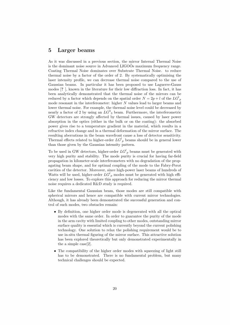
5.1 Cost and man power
The following cost estimate, which includes VAT, is a rough estimate based onnumbers from AdV construction for some parts. A detailed project is requiredfor an accurate costing.
For the two main R&D activities presented above the requested budget will bepresented separately. The execution time is meant to be three years.
R&D on larger beamsPersonnel 1 Post-doc 200 k€Equipment Mirror mechanics 30 k€
Optical table 20 k€Instrumentation for LG production 50 k€
Consumables Electronic components and photodiodes 50 k€TOTAL 300 k€
21
6 Squeezing
6.1 Introduction
Quantum noise limits the sensitivity of AdV above 30 Hz. Therefore a significantsensitivity enhancement can be achieved through reducing the quantum noisecontribution. This can be accomplished by injecting a frequency-dependentsqueezed vacuum field (FDS) into the interferometer’s dark port.
There are two steps to improve Virgo sensitivity by using squeezing: the firststep is to implement the frequency-independent squeezing (FIS) injection, achiev-able using current state-of-the-art technology (12 dB squeezing produced by thesqueezer before injection, 22% injection losses and 20 mrad phase jitter); thesecond step is to realise the FDS using an improved setup based on experi-mental parameters that should become realistic by 2020 when the FDS shallbe employed. In particular we can consider that at that time 15% of injectionlosses and 15 mrad phase jitter are achievable performance.
It is well known that an another way to shape the sensitivity and change theimpact of quantum noise gain in the sensitivity without squeezing, is to adoptthe detuned signal recycling configuration. The BNS range could be improveda bit with the detuned setting, doing even better than both the tuned and FIScases, but at the price of significant sensitivity reduction at high frequencies.The injection of frequency-dependent squeezing provides the best result for bothsimultaneously improving BNS range and high-frequency sensitivity.
So far, the most robust and efficient method to produce FDS is by rotating thesqueezing produced by a FIS system, by means of reflection from a filter cavity(FC) offset from the carrier. Recently this technique has been demonstratedexperimentally in the audio frequency band and thus could also be used inenhancing Advanced Virgo. It demands some further R&D with respect towhat is already available. In detail:
• Development of a vacuum state of light, with 12 dB squeezing being pro-duced/available in the acoustic frequency band: the source should operatein vacuum and be equipped with seismic isolation. An in-air source hasalready been developed by a few groups and prototypes are also underdevelopment by Virgo collaborators. The next step (suspended source ina vacuum environment) has not been fully developed yet and requires spe-cific R&D. The Virgo collaboration is considering the possibility to put theoptical bench of the squeezing source within a minitower in the detectionarea. The laser sources used in the generation of the squeezed state wouldinstead be housed on a standard bench close to the minitower.
• Development of a low loss system to inject the squeezed state. The min-imal requirement is injection losses at the level of 22%: this can only beachieved by reducing the losses of the detection path, with especially thedevelopment of custom Faraday isolators (3 on the squeezer bench and1 on the detection bench) having losses lower than 2% each in vacuum.Other parts, including the OMC, are expected to require some improve-ment. Optical losses are one of the most critical issues for taking advantage
22
of the squeezed state of light and has not yet been fully solved. Thus ithas high priority and should be addressed as soon as possible.
• Development of a single linear filter cavity: this geometry is motivated bythe requirement of minimizing optical losses to lower than 1ppm/m. A100 to 300 m long cavity with state-of-the-art mirror quality is estimatedto satisfy the loss requirement, having losses at the level of 0.2 ppm/m.The FC can be housed in the north-input arm, in a dedicated vacuumenclosure with mirrors suspended by “microtowers” (reduced version ofthe minitowers hosting mSAS and just a mirror or a very small opticaltable).
6.2 Implementation Plan
The squeezed light sensitivity enhancement for AdV will be implemented in twomain phases:
1. Development of the frequency-independent, in-vacuum, suspendedsqueezed light source and integration on AdV by 2017-18. The inte-gration of the squeezer should be made in the same time window requiredfor the installation of the other AdV upgrades.
The squeezing source will be used in the first years of the AdV operationas a FIS source to mitigate the risk related to high input optical power.Figure 1.4 of the AdV squeezing TDR shows that using FIS, the full power(125 W) sensitivity could be approached at much lower input power (25W).
To meet the short term integration plan, development of the in-vacuumsqueezer with all the related and necessary optical, electronic and me-chanical systems (auto-alignment systems, low loss ITF injection optics,in-vacuum electronics etc.) should start as soon as possible.
2. Filter cavity for frequency dependent squeezed light. Integrationon AdV in 2019-2020 or after the deployment of the full input laser power.
To convert FIS to FDS will require the FC after the in-vacuum squeezedsource. An early installation of its main infrastructures during the firstplanned upgrade of AdV in 2017-18 is highly recommended. The targetimprovements in injection losses and phase jitter will require R&D andcould be tested on the detector as enhancements of the FIS subsystem.
6.3 Cost Estimate
The following cost estimate is a rough estimate based on numbers from someparts of AdV construction (including VAT). These estimates do not includemanpower. A detailed project costing is required for greater accuracy.
23
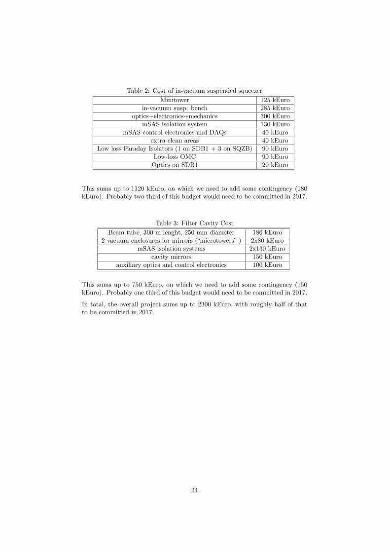
Table 2: Cost of in-vacuum suspended squeezer
Minitower 125 kEuroin-vacuum susp. bench 285 kEuro
optics+electronics+mechanics 300 kEuromSAS isolation system 130 kEuro
mSAS control electronics and DAQs 40 kEuroextra clean areas 40 kEuro
Low loss Faraday Isolators (1 on SDB1 + 3 on SQZB) 90 kEuroLow-loss OMC 90 kEuro
Optics on SDB1 20 kEuro
This sums up to 1120 kEuro, on which we need to add some contingency (180kEuro). Probably two third of this budget would need to be committed in 2017.
Table 3: Filter Cavity Cost
Beam tube, 300 m lenght, 250 mm diameter 180 kEuro2 vacuum enclosures for mirrors (“microtowers” ) 2x80 kEuro
mSAS isolation systems 2x130 kEurocavity mirrors 150 kEuro
auxiliary optics and control electronics 100 kEuro
This sums up to 750 kEuro, on which we need to add some contingency (150kEuro). Probably one third of this budget would need to be committed in 2017.
In total, the overall project sums up to 2300 kEuro, with roughly half of thatto be committed in 2017.
24
10-‐9
10-‐10
10-‐11
10 100 Frequency [Hz]
Displacemen
t spe
ctral noise [m
/(Hz
)-‐1/2 ]
7 The improvement of the detector robustness
The Improvement of the detector robustness
7.1 Anthropogenic noise reduction
In the figure 7.1 we report the measurements of the displacement noise per-formed using a high sentivitive seismometer Guralp CMG-40T during the com-missioning phase data taking of Virgo+. On the base of these spectra we pro-posed for advanced Virgo to move all the machineries still present in the centralarea out of the experimental buildings. It implies mainly to displace part of theauxiliary ultra high vacuum equipments and the rough pumps and to improvethe acoustic insulation of the duct paths.
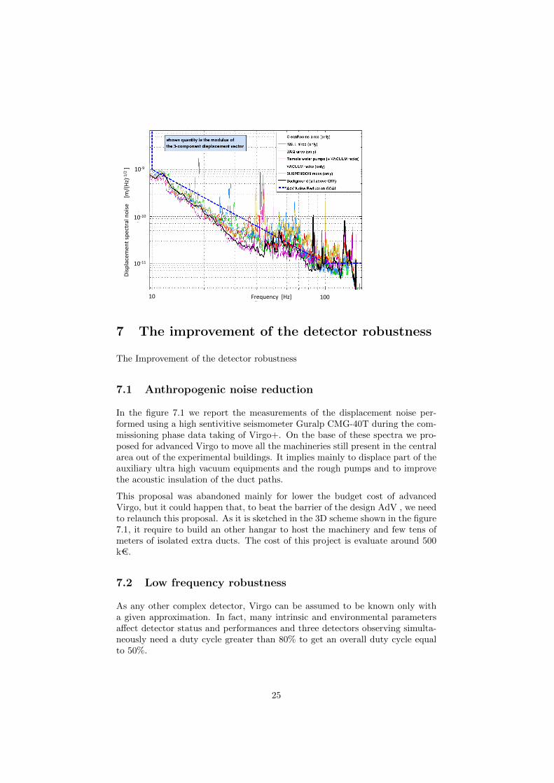
This proposal was abandoned mainly for lower the budget cost of advancedVirgo, but it could happen that, to beat the barrier of the design AdV , we needto relaunch this proposal. As it is sketched in the 3D scheme shown in the figure7.1, it require to build an other hangar to host the machinery and few tens ofmeters of isolated extra ducts. The cost of this project is evaluate around 500k€.
7.2 Low frequency robustness
As any other complex detector, Virgo can be assumed to be known only witha given approximation. In fact, many intrinsic and environmental parametersaffect detector status and performances and three detectors observing simulta-neously need a duty cycle greater than 80% to get an overall duty cycle equalto 50%.
25
For example, we know that large remote earthquakes can cause a stop of oper-ations for several minutes while large sea waves can make cavities lock acqui-sition and lock keeping difficult for few days each month. We also know thatsmall changes in temperature can cause suspensions length to vary significantly.Similarly, small changes in power stored in Virgo cavities can affect mirrorscurvature. All these parameters variations can produce a significative drop inobserving time penalising detector duty cycle. Moreover, most of our controlloops operate in small neighbourhood of n-dimensional working point, where wecan assume systems to be linear. In most cases, changing working point pro-duce very large variation of system parameters and therefore variation of controlloops performances that can produce a degradation of stability margins.
During last few years several techniques where studied and tested in Virgo to im-prove control loops robustness to system uncertainties and perturbation. Someof these techniques were already operative in Virgo+, for example a method toimprove robustness to tele-seism. Other techniques were simply studied like forexample predictive control of tidal strain. Adaptive algorithms were also studiedto improve, for example, lock time during windy days processing data producedby the detector itself together with environmental data. In parallel with al-gorithms we keep on investigating inertial sensors technologies with a specialattention to angular acceleration sensors and angular velocity sensors. Addingground tilt sensing capabilities to the Virgo detector will improve ground noiserejection.
Robust and adaptive control can significantly increase observing time and im-prove detector knowledge. Furthermore, detector performances will benefit froma reduction of noise injected into the system by non-optimal control loop designor non-optimally tuned sensors and actuators. At the same time, system de-signer will eventually have a clear view of specifications to be changed to obtainfurther improvements in the overall system performance.
In particular, the global control of the auxiliary degrees of freedom, along the
26
longitudinal and angular directions, are implemented in order to ensure highduty cycle and long period of data taking, but any noise in the associatedauxiliary degrees of freedom will couple to the gravitational wave channel atsome level.
The control noise of the auxiliary dofs is indeed a strong critical limiting factorat low frequency, below few tens of Hz, as it has been experienced in Virgo andVirgo+ [3] and in Advanced LIGO [4].
Several actions can be foreseen to mitigate and reduce the noise re-introductionin the gravitational wave signal such as using a real-time feed-forward cancella-tion techniques, improve the error signal SNR increasing the amount of poweron the photo-diodes and reduce the environmental and diffuse light noise.
7.3 The optical stability of the recycling cavities: the longcavity solution
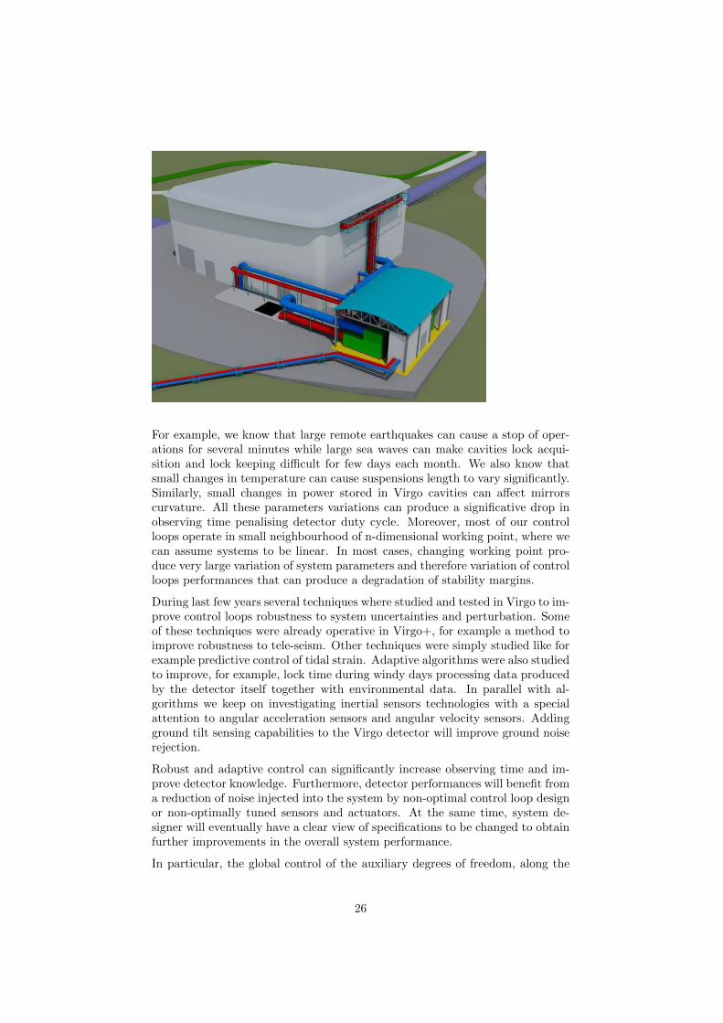
The present optical configuration of Advanced Virgo is based on the use of recy-cling optical cavities, that are marginally stable. This solution can make moredifficult the operation of the interferometer with higher power of the light storedin the cavities. The alternative solution is to use non degenerate recycling cavi-ties that should make simpler to achieve the optical stability. At the time of theapproval of the advanced Vigo project this approach has been excluded mainlyfor financial reasons. The scheme was based on the installation of long cavitiesimplying the construction of two smaller buildings and two vacuum tubes morethan 100 m long. as it is shown in the figure 7.3. A rough cost estimate of theinfrastructures and vacuum system has been performed, considering a redun-dant approach, that means to provide building, infrastructures and system ofthe same level of the ones presently used in Virgo, and the maximum possiblelength solution (180 m-long cavity for Power Recycling, and 80 m for SignalRecycling cavity).
27
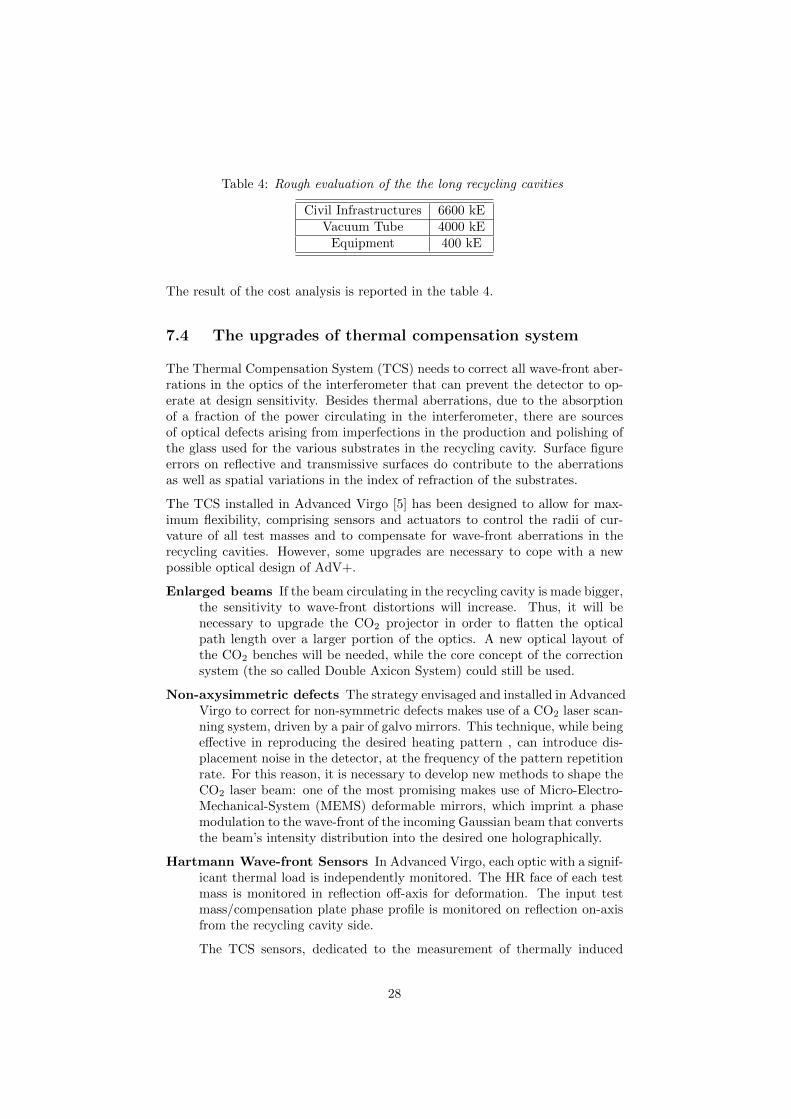
Table 4: Rough evaluation of the the long recycling cavities
Civil Infrastructures 6600 kEVacuum Tube 4000 kE
Equipment 400 kE
The result of the cost analysis is reported in the table 4.
7.4 The upgrades of thermal compensation system
The Thermal Compensation System (TCS) needs to correct all wave-front aber-rations in the optics of the interferometer that can prevent the detector to op-erate at design sensitivity. Besides thermal aberrations, due to the absorptionof a fraction of the power circulating in the interferometer, there are sourcesof optical defects arising from imperfections in the production and polishing ofthe glass used for the various substrates in the recycling cavity. Surface figureerrors on reflective and transmissive surfaces do contribute to the aberrationsas well as spatial variations in the index of refraction of the substrates.
The TCS installed in Advanced Virgo [5] has been designed to allow for max-imum flexibility, comprising sensors and actuators to control the radii of cur-vature of all test masses and to compensate for wave-front aberrations in therecycling cavities. However, some upgrades are necessary to cope with a newpossible optical design of AdV+.
Enlarged beams If the beam circulating in the recycling cavity is made bigger,the sensitivity to wave-front distortions will increase. Thus, it will benecessary to upgrade the CO2 projector in order to flatten the opticalpath length over a larger portion of the optics. A new optical layout ofthe CO2 benches will be needed, while the core concept of the correctionsystem (the so called Double Axicon System) could still be used.
Non-axysimmetric defects The strategy envisaged and installed in AdvancedVirgo to correct for non-symmetric defects makes use of a CO2 laser scan-ning system, driven by a pair of galvo mirrors. This technique, while beingeffective in reproducing the desired heating pattern , can introduce dis-placement noise in the detector, at the frequency of the pattern repetitionrate. For this reason, it is necessary to develop new methods to shape theCO2 laser beam: one of the most promising makes use of Micro-Electro-Mechanical-System (MEMS) deformable mirrors, which imprint a phasemodulation to the wave-front of the incoming Gaussian beam that convertsthe beam’s intensity distribution into the desired one holographically.
Hartmann Wave-front Sensors In Advanced Virgo, each optic with a signif-icant thermal load is independently monitored. The HR face of each testmass is monitored in reflection off-axis for deformation. The input testmass/compensation plate phase profile is monitored on reflection on-axisfrom the recycling cavity side.
The TCS sensors, dedicated to the measurement of thermally induced
28
distortions, consist of a Hartmann Wave-front Sensor (HWS), and a probebeam (at a different wavelength than the ITF beam) whose wave-frontcontains the thermal aberration information to be sensed.
The Hartmann sensor selected for Advanced Virgo is that already devel-oped and characterised on test bench experiments and in the Gingin HighOptical Power Test Facility for the measurement of wave-front distortion.This sensor has been demonstrated to have a shot-to-shot reproducibilityof λ/1450 at 820 nm, which improves to λ/15500 with averaging, and withan overall accuracy of λ/6800.
Recently, the DALSA Teledyne Company has put out of production thePantera 1M60 CCD, which is the core of the present HWS. Thus, it isabsolutely necessary to start an R&D activity to find another CCD withgood performances in terms of noise, fill factor, frame rate and satura-tion power and to design a new Hartmann plate and spacers in order tomaximise the performances of the wave-front sensors, by optimising theparameters over the new CCD, and guarantee or overcome the sensitivityof the present device.
Moreover, it has been demonstrated that the HWS is sensitive to fluctu-ations of the environmental temperature. While a control loop has beendeveloped and implemented, capable of stabilising the sensor’s tempera-ture within 5 mK, it would be desirable to minimize such sensitivity by aclever design of the Hartmann plate and spacers.
Laguerre-Gauss beams If the use of higher order Laguerre-Gauss modes(LG33) is considered to reduce the coating thermal noise, the CO2 projec-tor needs to be completely re-designed and re-built and an R&D activityshould start as soon as possible.
Adaptive optics for squeezing One of the main parameters that affect theamount of squeezing injected in the detector is the mode matching betweenthe interferometer beam and the squeezed beam. From the side of theinterferometer, TCS has the task to keep the ITF beam as Gaussian aspossible. However, the level of compensation that can be achieved cannotguarantee perfect Gaussianity. For this reason, it is advisable to start anR&D activity to develop an adaptive optical system that, acting on thesqueezed beam itself, would further improve the mode matching, withoutintroducing additional losses along the squeezed beam path.
The following cost estimate, which includes VAT, is a rough evaluation based onexpenses for AdV construction. A detailed project is required for an accuratecosting. The above mentioned upgrades for the three different scenarios requirethe items listed in the tables 5, 6 and 7Some of these items partially overlap, sothe total cost is not the sum of the single tasks, but it will be defined accordingto the design choices for AdV+.
The minimum required manpower is estimated to be one post-doc fellow forthree years. The costs for the three different scenarios .
29
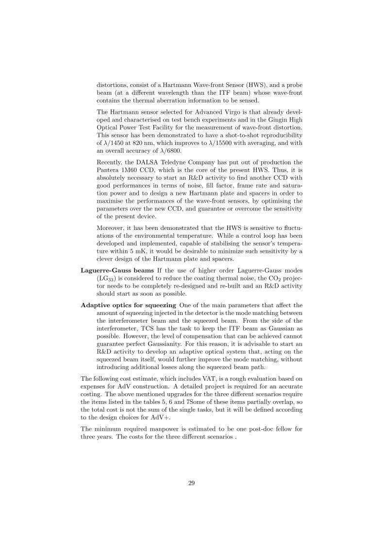
Table 5: Rough cost evaluation for the TCS Upgrade and R&D
Personnel 1 Post-doc fellow for three years 150 k€Equipment CO2 laser beam shaper 200 k€
New Hartmann sensors 200 k€Adaptive optics for squeezing 120 k€
TOTAL 670 k€
Table 6: Rough cost evaluation for the TCS Upgrade and R&D with enlargedbeams
Personnel 1 Post-doc fellow for three years 150 k€Equipment CO2 laser projector 100 k€
CO2 laser beam shaper 200 k€New Hartmann sensors 200 k€Adaptive optics for squeezing 120 k€
TOTAL 770 k€
8 Extending the arm length
In this section we report a rough analysis of this hypothetic change of the presentinfrastructure focusing our attention mainly on the potential impact on the landaround the EGO. We have to anticipate that the impact on the road network ason the water channels insuring the protection against flooding, can be easily astopover of this proposal. In any case, such a technical proposal is a subject onwhich many different authorities have to agree. In addition, seen the significantchange on the Cascina area to the respect the beginning of the Virgo, we cannotexclude that in few years from now this idea should be considered simply as animpossible dream. However, for completeness we present this preliminary study.
8.1 Motivation
The sensitivity is directly related to the arm length, since the strain is thedisplacement divided by the arm length. Most of the displacement noises, likethe thermal noise, or sensing noise are almost independent of the arm length.Increasing the arm length to 4 km like aLIGO would provide a 33% increasealmost independently of the frequency and therefore a 2.4 event rate increasefor all sources.
8.2 Discussion
The following image is showing the area at the end of both arms. The first housesalong the arm axis are around 4.5 km from the central building. Therefore, thepossibility for the arm extension is limited to about 4 km, which would matchthe LIGO arms length.
30
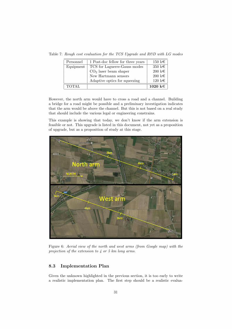
Table 7: Rough cost evaluation for the TCS Upgrade and R&D with LG modes
Personnel 1 Post-doc fellow for three years 150 k€Equipment TCS for Laguerre-Gauss modes 350 k€
CO2 laser beam shaper 200 k€New Hartmann sensors 200 k€Adaptive optics for squeezing 120 k€
TOTAL 1020 k€
However, the north arm would have to cross a road and a channel. Buildinga bridge for a road might be possible and a preliminary investigation indicatesthat the arm would be above the channel. But this is not based on a real studythat should include the various legal or engineering constrains.
This example is showing that today, we don’t know if the arm extension isfeasible or not. This upgrade is listed in this document, not yet as a propositionof upgrade, but as a proposition of study at this stage.
Figure 6: Aerial view of the north and west arms (from Google map) with theprojection of the extension to 4 or 5 km long arms.
8.3 Implementation Plan
Given the unknown highlighted in the previous section, it is too early to writea realistic implementation plan. The first step should be a realistic evalua-
31
tion of the project, investigating the technical and legal issues, land acquisitionfeasibility, establishing a timeline for the construction and a budget.
The construction itself should likely take several years, ending maybe at thetime of LIGO-India commissioning, a key parameter for the long term role ofthe Virgo infrastructure. It is not clear if, most of the construction, like thenew end buildings, could be done in parallel with data taking of AdV. In themore optimistic scenario we should lead to a down time for connecting the armextension and moving the terminal towers and suspension to maybe a year.
8.4 Cost and man power
It is obviously too early to give a robust estimate of the cost. Nevertheless, an or-der of magnitude could be derived from the Virgo construction cost (investment)that was 78 ME, including 18 MEuros for the tunnels. In first approximation,we can take one quarter of this cost for 1 km of arm plus the terminal buildingssince we can reuse the vacuum chambers, suspensions and the central buildingcontains more hardware. Then, adding 35% inflation from 1995 to 2016 plus15% contingency, we get 30 MEuros as very rough estimate.
32

9 Conclusion
The future evolution is summarised in a three-phase scenario:
• Phase 1 (2017-2021): achieve the design sensitivity
• Phase 2 (2021-2025): the best we can do in the current infrastructure
• Phase 3 (>2025): attempts for a further increase of the AdV sensitivityand useful in view of a new available infrastructure
In this document we have described a number of open technical options for theenhancement of AdV. Among those we expect that squeezing and subtractionof newtonian noise will be certainly implemented. The total investment forintegrating these mature technologies is expected to be of the order of 5M€.
R&D for the other options is strongly encouraged and their implementationwill be considered on the basis of the R&D outcomes and a tradeoff analysisevaluating the scientific payoff, the impact on the data taking plans, the budgetan schedule aspects.
The new 3 G detector will require a total investment ranging around 1B€. Seenthe scale of investment, a coordinated effort of several countries is needed. Itshould also cover dedicated R&D program with an expected cost in the rangearound 10 - 20 % of the total investment (for comparison, the cost of the R&Dprogram for aLIGO was about 30% of the project budget).
33
References
[1] The VIRGO collaboration. Advanced virgo technical design report. Techni-cal Report VIR-0128A-12, VIRGO-EGO, https://tds.ego-gw.it/ql/?c=8940,2012.
[2] A Allocca, A Gatto, M Tacca, RA Day, M Barsuglia, G Pillant, C Buy,and G Vajente. Higher-order laguerre-gauss interferometry for gravitational-wave detectors with in situ mirror defects compensation. Physical ReviewD, 92(10):102002, 2015.
[3] F. Acernese and et al. Automatic alignment system during the second sciencerun of the virgo interferometer. Astroparticle Physics, 34(6):327–332, 2011.
[4] LIGO collaboration. The sensitivity of the advanced ligo detectors at the be-ginning of gravitational wave astronomy. http://arxiv.org/abs/1604.00439.
[5] V. Fafone. VIR-0095A-10 - AdV Thermal Compensation System. Technicalreport, 2010.
34