a violin shell model: vibrational modes and acoustics 2015 shell modes.pdf · a generic physical...
TRANSCRIPT
A violin shell model: Vibrational modes and acoustics
Colin E. Gougha)
School of Physics and Astronomy, University of Birmingham, Birmingham B15 2TT, United Kingdom
(Received 17 May 2014; revised 6 February 2015; accepted 12 February 2015)
A generic physical model for the vibro-acoustic modes of the violin is described treating the body
shell as a shallow, thin-walled, guitar-shaped, box structure with doubly arched top and back plates.
COMSOL finite element, shell structure, software is used to identify and understand the vibrational
modes of a simply modeled violin. This identifies the relationship between the freely supported
plate modes when coupled together by the ribs and the modes of the assembled body shell. Such
coupling results in a relatively small number of eigenmodes or component shell modes, of which a
single volume-changing breathing mode is shown to be responsible for almost all the sound
radiated in the monopole signature mode regime below �1 kHz for the violin, whether directly or
by excitation of the Helmholtz f-hole resonance. The computations describe the influence on such
modes of material properties, arching, plate thickness, elastic anisotropy, f-holes cut into the top
plate, the bass-bar, coupling to internal air modes, the rigid neck-fingerboard assembly, and, most
importantly, the soundpost. Because the shell modes are largely determined by the symmetry of the
guitar-shaped body, the model is applicable to all instruments of the violin family.VC 2015 Acoustical Society of America. [http://dx.doi.org/10.1121/1.4913458]
[JW] Pages: 1210–1225
I. INTRODUCTION
Despite almost 200 years of research on the violin and
related instruments, summarized by Cremer1 and Hutchins,2
there has been a marked absence of a satisfactory physical
model to describe and account for their vibrational modes
and radiated sound—even for the prominent “signature mod-
es,” which dominate the frequency response of the radiated
sound over their first two octaves. The present paper, treating
the violin as a shallow, thin-walled, guitar shaped, shell
structure with doubly arched plates and a previous paper on
the vibrational modes of the individual plates3 attempt to
address this challenge.
In the earlier paper, the modes of the freely supported
top and back plates were described using COMSOL finite ele-
ment shell structure software4 as a quasi-experimental tool,
by varying parameters smoothly over a very wide range of
values, to demonstrate and thereby understand how the fre-
quencies and mode shapes of the individual plates are influ-
enced by their shape, broken symmetry, anisotropic physical
properties, arching, and f-holes. The influence on individual
plate vibrations of rib-constraints, the soundpost and bass-
bar were also demonstrated.
The present paper extends the methodology described in
the previous paper, to demonstrate the relationship between
the frequencies and shapes of the individual free plate modes
and those of the acoustically important low frequency modes
of the assembled body shell. The resulting eigenmodes or ba-sis normal modes of the in vacuo empty shell form a com-
plete orthogonal set of independent component modes,
which can be used to describe the perturbed modes in the
presence of a soundpost, in addition to their coupling to the
air within the cavity via the Helmholtz f-hole vibrations and
higher-order air modes. The resulting A0, CBR, B1�,
B1þ,…, set of independent (non-coupled) normal modes
describe the coupled component mode vibrations, observed
as resonances in admittance and sound radiation measure-
ments in the monopole signature mode frequency range
below �800 Hz–1 kHz for the violin.
This paper has a somewhat different focus from that of
most earlier finite element computations of the violin
body.5–8 Such investigations successfully reproduced many
of the often complex vibrational and acoustical asymmetric
modes using selected physical parameters for a particular
violin. In contrast, the aim of this paper has been to elucidate
the origin and physical principles underlying the generic
vibro-acoustic properties of the assembled instrument, with
less emphasis on predicting exact frequencies and mode
shapes. In practice, these will vary significantly in both value
and order among different members of the violin family (i.e.,
the violin, viola, cello, and arched-back double bass)—and
even between violins of comparable quality (Bissinger9,10).
Nevertheless, simple symmetry arguments suggest that
modes with very similar shapes and physical properties to
those described in the present paper will be observed for all
instruments of the violin family, with their vibro-acoustic
properties described by a single generic model.
Preliminary versions of the present model during earlier
stages in its development have been presented at a number
of previous conferences11–13 and informally at Oberlin
Violin Acoustics Workshops.
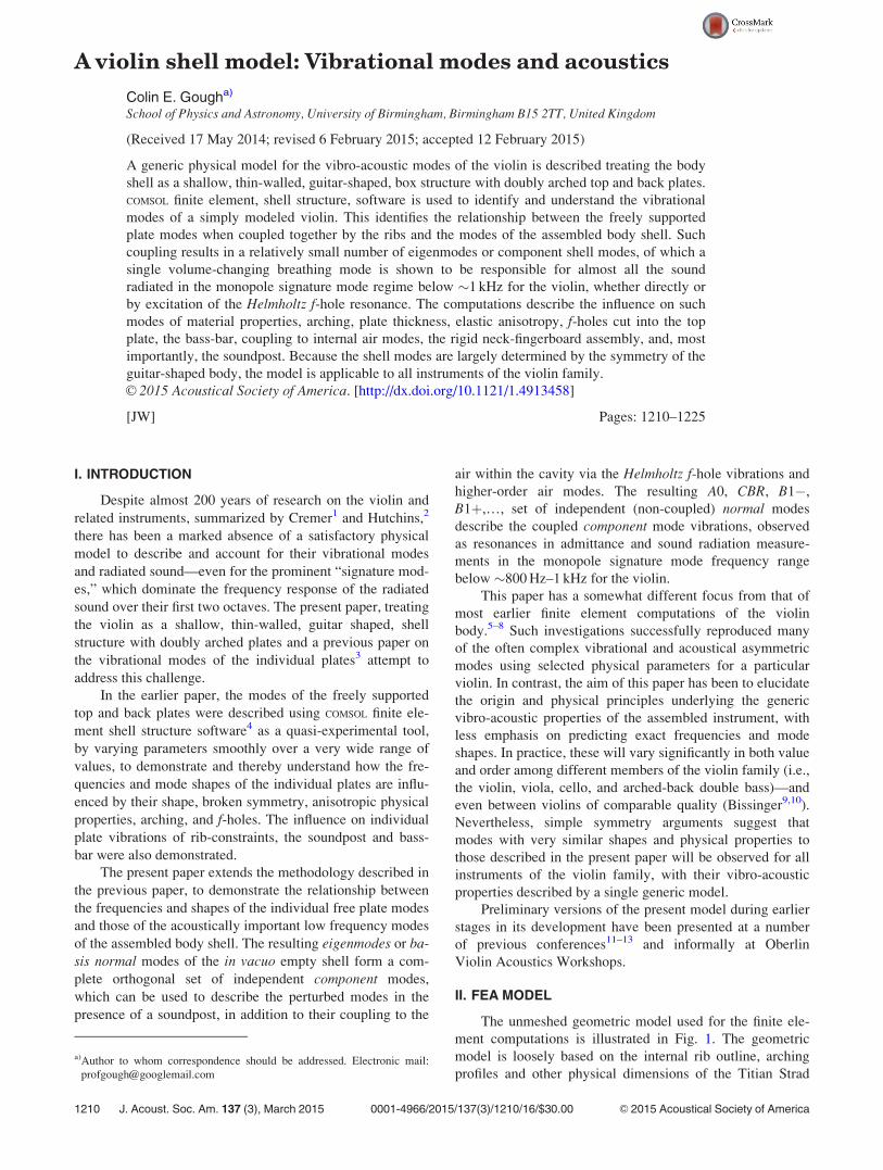
II. FEA MODEL
The unmeshed geometric model used for the finite ele-
ment computations is illustrated in Fig. 1. The geometric
model is loosely based on the internal rib outline, arching
profiles and other physical dimensions of the Titian Strad
a)Author to whom correspondence should be addressed. Electronic mail:
1210 J. Acoust. Soc. Am. 137 (3), March 2015 0001-4966/2015/137(3)/1210/16/$30.00 VC 2015 Acoustical Society of America
(Zygmuntowicz and Bissinger14). The arching and thickness
of the top and back plates are identical to those described in
the earlier paper on the individual top and back plate
modes.3 The influence of a simply modeled neck and finger-
board is also described.
The earlier paper on individual plate modes demon-
strated that, for a constant geometric mean of the orthotropic
along- and cross-grain Young’s moduli, variations in anisot-
ropy from unity to 25 had a relatively weak influence on the
computed #5=#2 freely supported arched plate mode fre-
quency ratio (typically �5%), though lowered their frequen-
cies by around 15%, consistent with a number of earlier
computations and measurements listed in Table I of Gough.3
The very weak dependence of the #5=#2 ratio on anisot-
ropy fails to support the widely accepted view that the #2
frequency is largely determined by the cross-grain Young’s
modulus and #5 frequency by the along-grain modulus. The
relative insensitivity of the modal frequencies to anisotropy
is a consequence of the two-dimensional nature of the stand-
ing flexural waves, which clearly involve both the along-
and cross-grain elastic constants.
Therefore, to keep the model as simple as possible and
without loss of generality, uniform thickness isotropic plates
were used with densities and elastic properties chosen to
give plate masses and freely supported mode frequencies
closely matching typical measured values.3 The generic
model is based on the recognition that the low-frequency
vibrational modes of the assembled shell are primarily deter-
mined by the symmetries, masses and modal frequencies of
the individual free plate modes, regardless of how such fre-
quencies are determined by variations in physical properties,
plate thicknesses and graduations, arching heights and pro-
files, and anisotropic elastic properties. This implies that the
exact shapes of the nodal lines of the freely supported plate
modes are rather less important than has sometimes been
assumed (for example, Hutchins15). This is unsurprising, as
the mode shapes of the individual plates are very different
when coupled by the ribs and offset soundpost, quite apart
from such shapes being unknown to the classic Cremonese
makers.
It is interesting to note that Cremer1 (Sec. 11.2) has
shown that, for a given geometric mean of the orthotropic
Young’s moduli—typically around 3.4 GPa for spruce and
4.7 GPa for maple,6 the density and spacing of the higher fre-
quency plate modes, when arching is no longer important, is
independent of anisotropy. The present model extends such
ideas to low frequencies, using isotropic plates with an
appropriately averaged anisotropic moduli chosen to repro-
duce the modal frequencies of the freely supported ortho-
tropic plates.
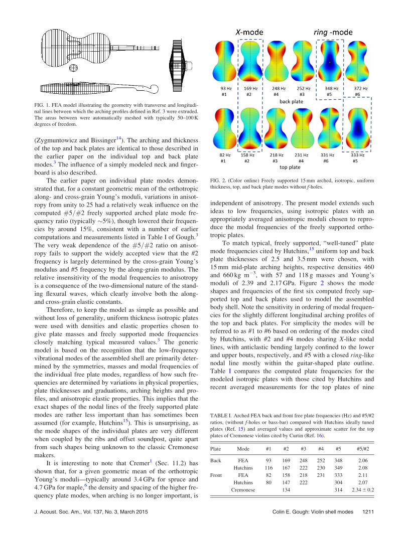
To match typical, freely supported, “well-tuned” plate
mode frequencies cited by Hutchins,15 uniform top and back
plate thicknesses of 2.5 and 3.5 mm were chosen, with
15 mm mid-plate arching heights, respective densities 460
and 660 kg m�3, with 57 and 118 g masses and Young’s
moduli of 2.39 and 2.17 GPa. Figure 2 shows the mode
shapes and frequencies of the first six computed freely sup-
ported top and back plates used to model the assembled
body shell. Note the sensitivity in ordering of modal frequen-
cies for the slightly different longitudinal arching profiles of
the top and back plates. For simplicity the modes will be
referred to as #1 to #6 based on ordering of the modes cited
by Hutchins, with #2 and #4 modes sharing X-like nodal
lines, with anticlastic bending largely confined to the lower
and upper bouts, respectively, and #5 with a closed ring-like
nodal line mostly within the guitar-shaped plate outline.
Table I compares the computed plate frequencies for the
modeled isotropic plates with those cited by Hutchins and
recent averaged measurements for the top plates of nine
FIG. 1. FEA model illustrating the geometry with transverse and longitudi-
nal lines between which the arching profiles defined in Ref. 3 were extruded.
The areas between were automatically meshed with typically 50–100 K
degrees of freedom.
TABLE I. Arched FEA back and front free plate frequencies (Hz) and #5/#2
ratios, (without f-holes or bass-bar) compared with Hutchins ideally tuned
plates (Ref. 15) and averaged values and approximate scatter for the top
plates of Cremonese violins cited by Curtin (Ref. 16).
Plate Mode #1 #2 #3 #4 #5 #5/#2
Back FEA 93 169 248 252 348 2.06
Hutchins 116 167 222 230 349 2.08
Front FEA 82 158 218 231 333 2.11
Hutchins 80 147 222 304 2.07
Cremonese 134 314 2.34 6 0.2
FIG. 2. (Color online) Freely supported 15 mm arched, isotropic, uniform
thickness, top, and back plate modes without f-holes.
J. Acoust. Soc. Am., Vol. 137, No. 3, March 2015 Colin E. Gough: Violin shell modes 1211
classic Cremonese instruments, including four Stradivari and
one Guarneri violin cited by Curtin.16
The computed values for the isotropic plate modes are
in close agreement with those of Hutchins, especially with
regard to the computed #5/#2 ratios of 2.08 6 0.03. The fre-
quencies of the computed modes can easily be uniformly
scaled by varying the assumed Young’s modulus. The #5/#2
ratio is slightly larger than 2.0, corresponding to the octave
tuning advocated by Hutchins,15 but smaller than the meas-
ured ratio of 2.34 6 0.20 for the nine Cremonese instruments
cited by Curtin.16 The computed #5/#2 computed frequen-
cies for the isotropic arched plate model are also in good
agreement with the extended set of measurements and com-
putations17,18 listed in Table I of Gough,3 given the inevita-
ble comparisons involving plates of different thicknesses
and graduations, arching heights and profiles, densities,
orthotropic elastic constants, with and without f-holes and
bass-bar, etc.
To demonstrate the influence of the ribs on the modes of
the assembled shell, typical ribs of height 3 cm, thickness
1 mm were used, with Young’s constant and density simulta-
neously scaled by the same factor from close to zero to typi-
cal values of 2 GPa and 660 kg m�3. The influence of the
f-holes was investigated by smoothly scaling the Young’s
constant and density of the f-hole areas from their normal
value to close to zero. Likewise, the influence of a 5 mm
diameter soundpost and simply shaped bass-bar were dem-
onstrated by simultaneously scaling their density and elastic
constant by the same factor. Such scaling leaves the longitu-
dinal and bending mode frequencies of the coupled compo-
nents unchanged from their normal high frequency values.
This avoids problems from the proliferation of low fre-
quency modes, were the elastic constants alone to be scaled.
To model the interaction of the plate mode vibrations
with the air inside the cavity, a simple Helmholtz model was
assumed, with the volume-changing plate vibrations induc-
ing a uniform acoustic pressure within the cavity. The
computed pressure fluctuations were then used to excite an
external disk representing the two plugs of air vibrating
through the f-holes, with the influence of the induced internal
cavity acoustic pressure fluctuations on the shell modes com-
puted self-consistently.
The soundpost of variable coupling strength was
assumed to be in intimate contact with the plates inhibiting
both relative displacements and bending across its ends. It
could be smoothly offset along and across the island area to
assess the influence of its position on the vibrational modes
and resulting excitation of radiated sound by the rocking
bridge. A tapered bass-bar of similar mass and elastic prop-
erties to those in real instruments could also be adiabatically
added to the shell, to investigate its influence on the vibra-
tional modes.
A simple rigid �2 g bridge was used to illustrate the
plate displacements and resulting radiation of sound in the
low frequency monopole regime, when excited by vertical
and horizontal bowing forces at the top of the bridge.
The computations were made using the structural shell
module of COMSOL multidisciplinary software.4 An auto-
mated mesh with typically � 50 K degrees of freedom was
generated, with the first 20 to 100 or so vibrational modes of
the freely supported instrument up to around 4 kHz typically
computed, processed, and displayed within a few tens of sec-
onds on a desk-top PC.
III. RIB COUPLING
The modes of the assembled shell formed from the
arched top and back plates have been computed as a function
of a generalized rib coupling strength, with the Young’s
modulus and density scaled by the same factor over several
orders of magnitude. Such scaling preserves the high fre-
quency longitudinal and bending wave modes at their normal
high values. The ribs therefore act as extensional and tor-
sional springs inhibiting relative plate displacements and
bending around their edges in all directions. To correspond
with usual practice, Young’s moduli were chosen to “tune”
the individual freely supported top and back plate #2 and #5
mode frequencies about a semi-tone apart.
The resulting, rather complicated, dependence of mode
frequencies on rib coupling strength is illustrated in Fig. 3.
For even very weak coupling, the ribs couple together the
initially freely supported plate modes with similar shapes
and frequencies to form pairs of normal modes, with the
individual plate modes vibrating in the same or opposite
phases. To distinguish between the two kinds of coupled
modes, these will be referred to as plate and corpus modes,
with (p0, p1, p2,…) and (c0, c1, c2,…) modes in order of
increasing frequency. The edge vibrations of the corpusmodes are strongly inhibited by the extensional, spring-like,
constraints of the ribs resulting in a rapid increase in mode
frequency, with the edges first becoming pinned then
clamped to the rib plane at sufficient rib-coupling strength.
In contrast, the plate modes, with flexural plate vibrations in
the same sense, retain their large edge displacements, with
the bending around their edges less strongly constrained by
the bending of the ribs rather than extensional forces. This
results in a much slower increase in their frequency with
increasing rib-coupling strength.
On increasing coupling strength, six new low-frequency
modes emerge with frequencies proportional to the square
root of the rib coupling strength. As described in the earlier
paper on the individual plates,3 these modes originate from
the original twelve, rigid body, translational and rotational
modes of the two freely supported plates along and about the
three symmetry related orthogonal axes. Six such zero-
frequency modes are still required to describe the rigid body
displacement and rotational motions of the freely supported
assembled shell. The remaining six modes describe the dis-
placements and rotations of the top and back plates in oppo-
site directions constrained by the ribs, illustrated
schematically below the plot in Fig. 3. Their frequencies are
proportional toffiffiffiffiffiffiffiffiffiffiffiffiffiffiffiffiffiffiffiffiffiffiKrib=Mplates
por
ffiffiffiffiffiffiffiffiffiffiffiffiffiffiffiffiffiffiffiffiGrib=Iplates
p, with effective
linear and torsional rib spring-constants K and G and effec-
tive masses and moments of inertia M and I, which will
depend on the distribution of mass and geometry of the indi-
vidual plates. Their frequencies therefore initially increase
as a function of increasing rib strength with slope 1/2, when
plotted in Fig. 3 on logarithmic scales.
1212 J. Acoust. Soc. Am., Vol. 137, No. 3, March 2015 Colin E. Gough: Violin shell modes
When sharing similar symmetry elements (i.e., a non-
zero value of the integrated product of their surface displace-
ments over the surface of both plates), these modes cross and
interact with the rib-coupled flexural wave modes of the
plates. This leads to the rather complicated set of normalmodes describing their coupled vibrations, with multiple
veering and splitting of mode frequencies, which are not im-
mediately easy to interpret.
Despite such complications, as one approaches normal
coupling strengths, the mode diagram simplifies, with only a
small number of modes remaining in the low-frequency sig-
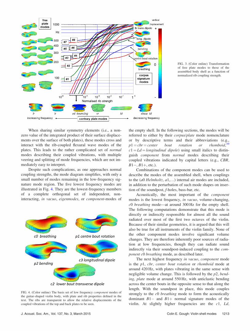
nature mode region. The five lowest frequency modes are
illustrated in Fig. 4. They are the lowest-frequency members
of a complete orthogonal set of independent, non-
interacting, in vacuo, eigenmodes, or component-modes of
the empty shell. In the following sections, the modes will be
referred to either by their corpus/plate mode nomenclature
or by descriptive terms and their abbreviations (e.g.,
p1¼ cbr¼ center bout rotation or rhomboid,10
c1¼Ld¼ longitudinal dipole) using small italics to distin-
guish component from normal modes describing their
coupled vibrations indicated by capital letters (e.g., CBR,B1�, B1þ, etc.).
Combinations of the component modes can be used to
describe the modes of the assembled shell, when couplings
to the (a0 Helmholtz, a1,…) internal air modes are included,
in addition to the perturbation of such mode shapes on inser-
tion of the soundpost, f-holes, bass-bar, etc.
Acoustically, the most important of the componentmodes is the lowest frequency, in vacuo, volume-changing,
c0 breathing mode—at around 300 Hz for the empty shell.
The following computations demonstrate that this mode is
directly or indirectly responsible for almost all the sound
radiated over most of the first two octaves of the violin.
Because of their similar geometries, it is argued that this will
also be true for all instruments of the violin family. None of
the other component modes involve significant volume
changes. They are therefore inherently poor sources of radia-
tion at low frequencies, though they can radiate sound
indirectly via their soundpost-induced coupling to the com-ponent c0 breathing mode, as described later.
The next highest frequency in vacuo, component mode
is the p1, cbr, center bout rotation or rhomboid mode at
around 420 Hz, with plates vibrating in the same sense with
negligible volume change. This is followed by the p2, bend-ing, plate mode at around 550 Hz, with anticlastic bending
across the center bouts in the opposite sense to that along the
length. With the soundpost in place, this mode couples
strongly to the c0 breathing mode to form the acoustically
dominant B1� and B1þ normal signature modes of the
violin. At slightly higher frequencies are the c1, Ld,
FIG. 3. (Color online) Transformation
of free plate modes to those of the
assembled body shell as a function of
normalized rib coupling strength.
FIG. 4. (Color online) The basis set of low frequency component modes of
the guitar-shaped violin body, with plate and rib properties defined in the
text. The ribs are transparent to allow the relative displacements of the
coupled vibrations of the top and back plates to be seen.
J. Acoust. Soc. Am., Vol. 137, No. 3, March 2015 Colin E. Gough: Violin shell modes 1213
longitudinal dipole and c2, ltd, lower bout transverse dipolecomponent modes. None of the other component shell modes
involve significant volume changes and are therefore
intrinsically weak sources of monopole radiation below
1 kHz, other than a largely top plate, volume-changing,
mode at around 800 Hz, with three flexural half-wavelengths
along the length.
Despite the complexity introduced by the interactions
between the plates, the ribs and the quasi-rigid plate vibra-
tions, the number of normal modes describing their coupled
motions is always conserved. Because the empty shell is
symmetric with respect to the central longitudinal axis, the
modes are either symmetric or anti-symmetric with respect
to the longitudinal axis. Provided the geometrical symmetry
is maintained, only those modes sharing a similar symmetry
can interact to form normal modes characterized by the veer-
ing and splitting of their frequencies, around the region
where their frequencies would otherwise have crossed.
In the following section, the apparent complexity of the
rib-coupled plate modes illustrated in Fig. 3 will be simpli-
fied, by extracting those parts of the dispersion curves, which
illustrate how the individual freely supported plate modes
are transformed into the above set of component modes.
IV. FROM FREE PLATE TO SHELL MODES
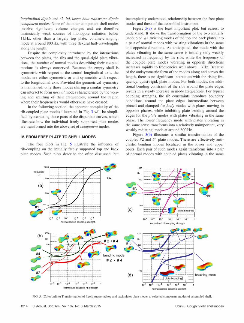
The four plots in Fig. 5 illustrate the influence of
rib-coupling on the initially freely supported top and back
plate modes. Such plots describe the often discussed, but
incompletely understood, relationship between the free plate
modes and those of the assembled instrument.
Figure 5(a) is the least important plot, but easiest to
understand. It shows the transformation of the two initially
uncoupled #1 twisting modes of the top and back plates into
a pair of normal modes with twisting vibrations in the same
and opposite directions. As anticipated, the mode with the
plates vibrating in the same sense is initially only weakly
increased in frequency by the ribs, while the frequency of
the coupled plate modes vibrating in opposite directions
increases rapidly to frequencies well above 1 kHz. Because
of the antisymmetric form of the modes along and across the
length, there is no significant interaction with the rising fre-
quency, quasi-rigid, plate modes. For both modes, the addi-
tional bending constraint of the ribs around the plate edges
results in a steady increase in mode frequencies. For typical
coupling strengths, the rib constraints introduce boundary
conditions around the plate edges intermediate between
pinned and clamped for body modes with plates moving in
opposite phases, while inhibiting plate bending around the
edges for the plate modes with plates vibrating in the same
phase. The lower frequency mode with plates vibrating in
the same sense transforms into a relatively unimportant, very
weakly radiating, mode at around 800 Hz.
Figure 5(b) illustrates a similar transformation of the
coupled #2 and #4 plate modes. These are effectively anti-
clastic bending modes localized in the lower and upper
bouts. Each pair of such modes again transforms into a pair
of normal modes with coupled plates vibrating in the same
FIG. 5. (Color online) Transformation of freely supported top and back plates plate modes to selected component modes of assembled shell.
1214 J. Acoust. Soc. Am., Vol. 137, No. 3, March 2015 Colin E. Gough: Violin shell modes
or opposite directions. As before, the modes with plates
vibrating in opposite directions increase rapidly with fre-
quency, to produce a pair of high frequency modes well
above 1 kHz. In contrast, the pair of modes with plates
vibrating in the same direction increase in frequency much
more slowly. They are themselves coupled together by the
ribs to form a new pair of normal modes. The lowest fre-
quency mode, at around 550 Hz at full strength rib coupling,
is the important anticlastic p1 bending plate mode formed
from the localized lower #2 and upper #4 anticlastic bending
of the two plates vibrating in the same direction. The upper
frequency mode transforms into an unimportant acoustic
mode with anticlastic bending mode in the lower bouts and a
breathing mode in the upper—from its coupling to other
higher frequency component modes, but with very little
volume change, hence negligible monopole radiation source
strength.
Figures 5(c) and 5(d) are more interesting, as they
involve strong interactions with the rapidly rising frequency,
quasi-rigid, contrary-motion, plate modes. On increasing the
coupling strength, the coupled initial top and back plate, #3,
whole wavelength, twisting modes form a pair of normalmodes, with the upper mode with plates vibrating in opposite
senses again rapidly increasing in frequency to well above 1
kHz. In contrast, the mode with plates vibrating in the same
sense interacts strongly with the quasi-rigid transverseshearing mode resulting in significant veering and splitting
of the resulting normal mode frequencies, where otherwise
they would cross. For typical rib strengths this leads to the
formation of the CBR normal mode, which describes the
coupled #3 rotations of the freely supported plates with a
strong shearing contribution from the coupled quasi-rigid,contrary-motion, shearing mode.
Finally, and most importantly, Fig. 5(d) illustrates the
influence of rib coupling on the coupled free-plate #5 ringmodes. As the rib coupling strength increases, the increasing
frequency bouncing component mode transforms smoothly
into the acoustically important, volume-changing, initially invacuo, c0 breathing mode of the assembled shell just below
300 Hz. The coupled #5 modes with plates vibrating in the
same sense are smoothly transformed into a largely top plate
mode at �820 Hz, with effectively three half-wavelength
standing flexural waves along the length. This higher fre-
quency mode involves a net volume change and provides
another potentially significant source of monopole radiation
at the upper frequency end of the signature mode regime, as
confirmed by later radiated sound computations. The tend-
ency for modes to be localized in either the top or back
plates of either the lower and upper bouts is an ubiquitous
feature of many of the higher frequency component modes.
There is a further complication, as flexural waves on the
arched plates induce longitudinal strains leading to signifi-
cant in-plane edge displacements. Such displacements are
constrained by induced longitudinal strains around the outer
edges of the arched plates, resulting in the strong depend-
ence of the plate frequencies on arching height. The in-plane
edge displacements also induce longitudinal strains around
the supporting rib garland. Sufficiently strong rib constraints
would inhibit all such edge displacements resulting in a very
large increase in the breathing mode frequency, in particular.
Characterizing the properties of individual plates before as-
sembly by measuring their modal frequencies when clamped
to a rigid frame, as has sometimes been suggested, would
therefore significantly over-estimate their vibrational fre-
quency, when supported on the more flexible rib garland.
In contrast, measuring the vibrational frequency of the
plates resting on a frictionless flat surface would, if possible,
give a much better estimate for the in vacuo breathing vibra-
tional modes of the individual plates on the assembled
instrument. For a given plate mass M such frequencies will
be closely related to the effective spring constant K of the
plates resting on a flat surface (/ffiffiffiffiffiffiffiffiffiffiK=M
p), when pushed
downwards at its center—a tactile assessment of plate flexi-
bility, which might easily have been used by early
Cremonese makers.
Although there is no direct relationship between the fre-
quencies of the freely supported #5 modes and shell modes,
when pinned or clamped around their edges by the ribs, for a
given arching profile and other plate properties, there will
always be a numerical relationship between their frequen-
cies. The in vacuo breathing mode frequency will then be a
weighted average of the top and back pinned/clamped fre-
quencies. However, as demonstrated below, the breathingmode frequency, in particular, is strongly perturbed by the
air within the cavity, the soundpost coupling strength and
position and its coupling to the bending component mode.
Such interactions will dominate the frequencies and separa-
tion of the resulting B1� and B1þ signature modes, obscur-
ing any simple correlation between their frequencies and
those of the #2 and #5 freely supported plates. This is con-
sistent with the lack of any such correlation in an extensive
set of measurements of the modes of the freely supported
plates and assembled violin at various stages in its construc-
tion by Schleske.19
V. F-HOLES AND ISLAND AREA
The f-holes cut into the top plate serve two important
functions. First, they provide two openings through which
air can bounce in and out, forming a Helmholtz resonator
driven by the volume-changing, c0 component breathingmode. Their coupled vibrations form the A0 and the breath-ing normal modes with the A0 f-hole resonance frequency
depressed below that of the ideal rigid-walled Helmholtz
resonator and C0 mode frequency raised above that of its
uncoupled value, with very little change in its volume-
changing, breathing, mode shape. This will still be referred
to as the breathing mode, though it also includes its coupling
to the Helmholtz vibrations. As is well known, the excitation
of the Helmholtz air resonance significantly boosts the radi-
ated sound at frequencies over most of the first two octaves
of the violin and other instruments of the violin family.
Second, the f-holes introduce an increased flexibility
island area between their inner edges (Cremer,1 Sec. 10.1).
Its broad opening at the lower-bout end and constricted
opening between the upper-bout eyes creates the equivalent
of a narrowing two-dimensional wave-guide for flexural
waves. This enhances the penetration of flexural waves from
J. Acoust. Soc. Am., Vol. 137, No. 3, March 2015 Colin E. Gough: Violin shell modes 1215
the lower bout into the island area, increasing their coupling
to the rocking bridge, with the narrowed distance between
the upper eyes inhibiting coupling from the upper bout vibra-
tions. The flexural wave amplitudes at the feet of the bridge
ultimately determine the intensity and quality of the radiated
sound excited by the bowed strings. Hence the shape of the
island area formed by the f-holes is important.
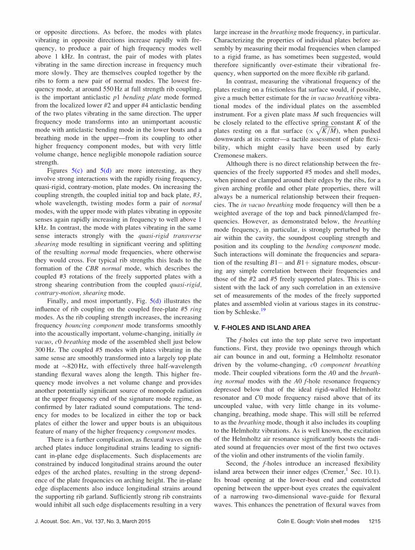
A. Influence of f-holes on shell modes
To simulate the influence of the f-holes, the Young’s
modulus and density of the f-hole areas were reduced by the
same factor from unity (no f-holes) to a very low value (fully
open), as illustrated in Fig. 6, with their influence on the
principal component mode shapes also illustrated. The f-holes clearly decrease the frequencies of all the modes to
some extent, but scarcely change the frequencies of the
acoustically important breathing and bending componentmodes of the violin. Nevertheless, as illustrated by the
accompanying shell mode shapes, they have a major influ-
ence on the vibrations and mode shapes in the waist/island
areas, often leading to enhanced amplitude vibrations
towards the upper end of the island area.
B. The Helmholtz resonance and coupling to thebreathing mode
To understand the influence of coupling of the plate
modes to the air inside the body-shell, the cavity was consid-
ered as an ideal, rigid-walled, Helmholtz resonator with a
uniform internal acoustic pressure and resonant frequency
ðco=2pÞffiffiffiffiffiffiffiffiffiffiffiffiA=LV
p, where A is the combined area of the
f-holes, L their effective neck lengths, V the cavity volume,
and co the speed of sound. Although co and the Helmholtz
frequency are independent of ambient pressure, its coupling
to the breathing mode increases with the density of the air,
which increases with ambient pressure.
The induced pressure fluctuations excited by the cavity
wall vibrations and the additional loading on the cavity wall
vibrations from the Helmholtz pressure fluctuations were
computed self-consistently from the combined changes in
volume from the component shell mode vibrations and the
induced vibrations of the plugs of air bouncing in and out of
the f-holes (Cremer,1 Sec. 10.3). The effective area and
length of the f-holes were similar to those estimated by
Cremer, and were chosen to give an ideal Helmholtz
frequency of 300 Hz.
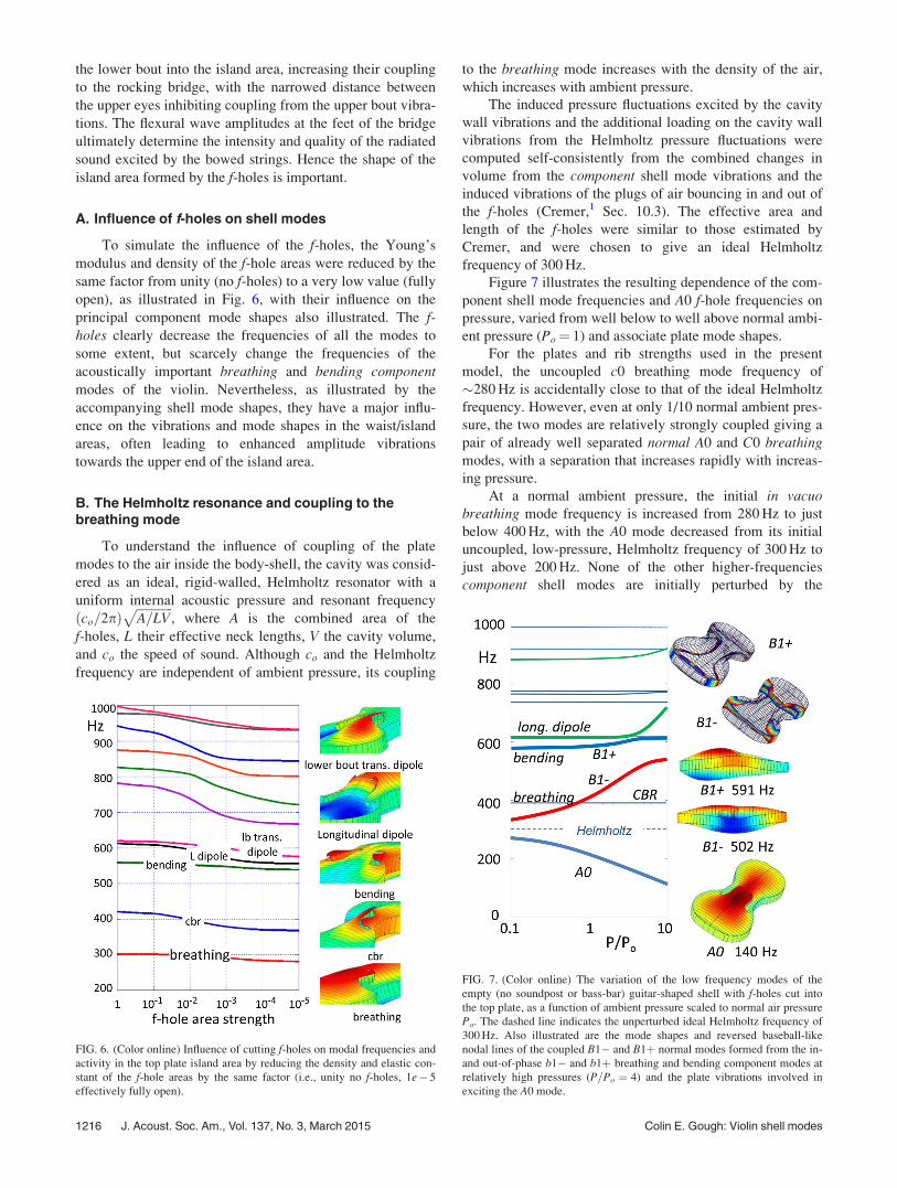
Figure 7 illustrates the resulting dependence of the com-
ponent shell mode frequencies and A0 f-hole frequencies on
pressure, varied from well below to well above normal ambi-
ent pressure (Po¼ 1) and associate plate mode shapes.
For the plates and rib strengths used in the present
model, the uncoupled c0 breathing mode frequency of
�280 Hz is accidentally close to that of the ideal Helmholtz
frequency. However, even at only 1/10 normal ambient pres-
sure, the two modes are relatively strongly coupled giving a
pair of already well separated normal A0 and C0 breathingmodes, with a separation that increases rapidly with increas-
ing pressure.
At a normal ambient pressure, the initial in vacuobreathing mode frequency is increased from 280 Hz to just
below 400 Hz, with the A0 mode decreased from its initial
uncoupled, low-pressure, Helmholtz frequency of 300 Hz to
just above 200 Hz. None of the other higher-frequencies
component shell modes are initially perturbed by the
FIG. 6. (Color online) Influence of cutting f-holes on modal frequencies and
activity in the top plate island area by reducing the density and elastic con-
stant of the f-hole areas by the same factor (i.e., unity no f-holes, 1e� 5
effectively fully open).
FIG. 7. (Color online) The variation of the low frequency modes of the
empty (no soundpost or bass-bar) guitar-shaped shell with f-holes cut into
the top plate, as a function of ambient pressure scaled to normal air pressure
Po. The dashed line indicates the unperturbed ideal Helmholtz frequency of
300 Hz. Also illustrated are the mode shapes and reversed baseball-like
nodal lines of the coupled B1� and B1þ normal modes formed from the in-
and out-of-phase b1� and b1þ breathing and bending component modes at
relatively high pressures (P=Po ¼ 4) and the plate vibrations involved in
exciting the A0 mode.
1216 J. Acoust. Soc. Am., Vol. 137, No. 3, March 2015 Colin E. Gough: Violin shell modes
increase in pressure—because no volume changes are
involved, so they cannot excite the Helmholtz resonator. The
volume-changing breathing mode alone is therefore the
major source of sound at low pressures, either radiated
directly or indirectly by excitation of the Helmholtz mode.
As the ambient pressure is increased, the increased cou-
pling between the breathing and Helmholtz modes results in
a strong increase in breathing mode frequency and a
decrease in frequency of the A0 mode. The symmetric
breathing mode frequency then crosses the antisymmetric
cbr mode frequency with no veering or splitting, as the
modes are uncoupled. However, as the breathing mode fre-
quency rises still higher, it approaches and would otherwise
cross the symmetric bending mode frequency. This leads to
a strong veering and splitting of frequencies of the resulting
B1� and B1þ normal modes describing their in- and out-of
phase vibrations. At still higher pressures, the rising fre-
quency B1þ mode crosses the longitudinal dipole mode,
with a small amount of veering and splitting. At still higher
pressures, the largely breathing mode component of the B1þmode approaches two other higher frequency modes, with
their ambient-pressure induced coupling raising their fre-
quencies. The two modes are subsequently identified as the
anti-breathing mode, with the two plates vibrating with
different amplitudes in their fundamental modes, but in the
same phase, and a largely top-plate L3 mode, with effec-
tively three half-wavelength standing waves along the
length. Both these modes make a significant contribution to
the sound at the higher end of the signature mode regime, as
shown by later simulated radiativity measurements.
The upper B1� and B1þ mode shapes for a high ambi-
ent pressure of P=Po ¼ 4 in Fig. 7 demonstrate the in- and
out-of-phase coupled vibrations of the component bendingand breathing modes. The top two figures illustrate the
observed reversal of base-ball like nodal lines circulating the
body shell. This is a characteristic feature of the coupled
bending and breathing modes—even in simpler shallow rec-
tangular and trapezoidal box structures.11 The bottom figure
shows the plate vibrations at the A0 frequency, which are
clearly those of the component breathing mode exciting the
component Helmholtz vibrations.
In practice, the assumption of uniform acoustic pressure
for the Helmholtz mode will overestimate the coupling
between the vibrating plates and Helmholtz resonator. This
is because the induced acoustic pressure along the central
axis in line with the f-hole notches drops to around 0.7 of its
average value resulting from the induced flow of air and
acoustic pressure drops towards the f-hole from the upper
and lower bouts.20–22 Additional higher order cavity air
modes must therefore also be excited, to ensure a spatially
uniform acoustic pressure within the cavity at low frequen-
cies. As a first approximation, such corrections have been
ignored, as the aim is to understand the underlying physics
rather than introducing further complications, which can
always be considered once the basic physics is established.
It is interesting to compare the shapes and frequencies
of the above “empty shell” modes with f-holes and coupling
to the air within the cavity with modal analysis measure-
ments by George Stoppani for a number of high quality
modern instruments, before the neck/fingerboard assembly
and soundpost is added. The advantage of making such
measurements at this stage in the construction is that adjust-
ments to the individual plates can still be relatively easily
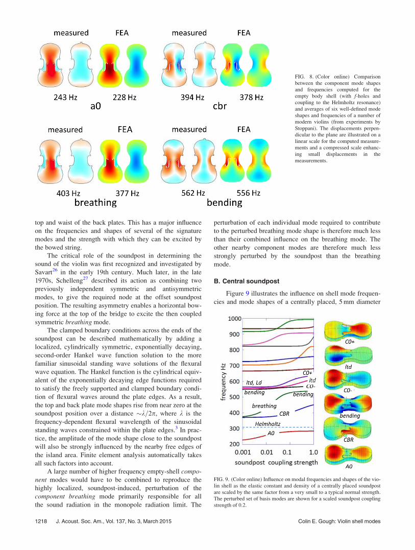
made. Such a comparison is illustrated in Fig. 8, which com-
pares averaged mode shapes and frequencies for typically
six clearly defined examples of well-defined modes on
different instruments with computed frequencies and mode
shapes for the present “well-tuned” isotropic plate model,
Although the simplified model has primarily been developed
as an aid to identifying and understanding the important
signature modes of the violin, the close agreement between
the computed and measured mode shapes and frequencies is
gratifying and supports the validity and usefulness of the
proposed model.
The strong coupling between the breathing and bendingmodes arises from the differential longitudinal strains
induced by flexural waves on the arched top and back plates.
If the top and back plates were identical, their edge displace-
ments would be the same, with no tendency for the plates to
bend. However, the thinner top plate incorporating the island
area is more flexible than the back plate. For similar arching
heights and different vibrational amplitudes, the induced in-
plane top plate edge displacements will be larger than those
of the back plate resulting in a bending of the body shell.
This is closely analogous to the bending of a heated
bi-metallic strip—from the differential expansions of the
upper and lower strips caused by changes in temperature.
Later computations of the radiated sound confirm that
the component breathing mode is indeed responsible directly
and indirectly for almost all the sound radiated by the violin
in the monopole, signature mode, regime below around
1 kHz. The relative radiating monopole source strengths of
the B1� and B1þ signature modes are therefore determined
by the relative strengths of the coupled breathing componentmode in each. Because the coupling results in mode-
splitting, the B1� and B1þ mode frequencies are always
separated by an amount equal to or greater than their split-
ting at the frequency where the uncoupled breathing and
bending component modes would otherwise have crossed.
For the violin, the radiating strength of the B1� and
B1þ modes are usually similar, but vary significantly
between instruments of even the finest quality. Their relative
strengths may well be very different for different sized
instruments. For example, the frequency response of the
arched-back double bass has only a single dominant radiat-
ing B1 breathing mode above the A0 resonance,23–25 pre-
sumably because there is no nearby bending mode to couple
to.
VI. SOUNDPOST
A. Overview
The soundpost introduces a localized clamped boundary
condition inhibiting relative displacements and rotations of
the two plates across its ends. The resulting depression of
plate vibrations in the vicinity of the soundpost ends acts as
a barrier inhibiting the penetration of the lower and upper
bout plate vibrations into and across the island area of the
J. Acoust. Soc. Am., Vol. 137, No. 3, March 2015 Colin E. Gough: Violin shell modes 1217
top and waist of the back plates. This has a major influence
on the frequencies and shapes of several of the signature
modes and the strength with which they can be excited by
the bowed string.
The critical role of the soundpost in determining the
sound of the violin was first recognized and investigated by
Savart26 in the early 19th century. Much later, in the late
1970s, Schelleng27 described its action as combining two
previously independent symmetric and antisymmetric
modes, to give the required node at the offset soundpost
position. The resulting asymmetry enables a horizontal bow-
ing force at the top of the bridge to excite the then coupled
symmetric breathing mode.
The clamped boundary conditions across the ends of the
soundpost can be described mathematically by adding a
localized, cylindrically symmetric, exponentially decaying,
second-order Hankel wave function solution to the more
familiar sinusoidal standing wave solutions of the flexural
wave equation. The Hankel function is the cylindrical equiv-
alent of the exponentially decaying edge functions required
to satisfy the freely supported and clamped boundary condi-
tion of flexural waves around the plate edges. As a result,
the top and back plate mode shapes rise from near zero at the
soundpost position over a distance �k=2p, where k is the
frequency-dependent flexural wavelength of the sinusoidal
standing waves constrained within the plate edges.3 In prac-
tice, the amplitude of the mode shape close to the soundpost
will also be strongly influenced by the nearby free edges of
the island area. Finite element analysis automatically takes
all such factors into account.
A large number of higher frequency empty-shell compo-nent modes would have to be combined to reproduce the
highly localized, soundpost-induced, perturbation of the
component breathing mode primarily responsible for all
the sound radiation in the monopole radiation limit. The
perturbation of each individual mode required to contribute
to the perturbed breathing mode shape is therefore much less
than their combined influence on the breathing mode. The
other nearby component modes are therefore much less
strongly perturbed by the soundpost than the breathing
mode.
B. Central soundpost
Figure 9 illustrates the influence on shell mode frequen-
cies and mode shapes of a centrally placed, 5 mm diameter
FIG. 8. (Color online) Comparison
between the component mode shapes
and frequencies computed for the
empty body shell (with f-holes and
coupling to the Helmholtz resonance)
and averages of six well-defined mode
shapes and frequencies of a number of
modern violins (from experiments by
Stoppani). The displacements perpen-
dicular to the plane are illustrated on a
linear scale for the computed measure-
ments and a compressed scale enhanc-
ing small displacements in the
measurements.
FIG. 9. (Color online) Influence on modal frequencies and shapes of the vio-
lin shell as the elastic constant and density of a centrally placed soundpost
are scaled by the same factor from a very small to a typical normal strength.
The perturbed set of basis modes are shown for a scaled soundpost coupling
strength of 0.2.
1218 J. Acoust. Soc. Am., Vol. 137, No. 3, March 2015 Colin E. Gough: Violin shell modes
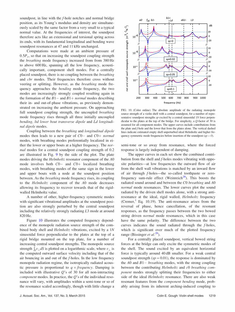
soundpost, in line with the f-hole notches and normal bridge
position, as its Young’s modulus and density are simultane-
ously scaled by the same factor from a very small to a typical
normal value. At the frequencies of interest, the soundpost
therefore acts like an extensional and torsional spring across
its ends, with its fundamental longitudinal and bending wave
soundpost resonances at 47 and 11 kHz unchanged.
Computations were made at an ambient pressure of
0:5Po, so that on increasing the soundpost coupling strength
the breathing mode frequency increased from from 380 Hz
to above 600 Hz, spanning all the low frequency, acousti-
cally important, component shell modes. For a centrally
placed soundpost, there is no coupling between the breathingand cbr modes. Their frequencies therefore cross without
veering or splitting. However, as the breathing mode fre-
quency approaches the bending mode frequency, the two
modes are increasingly strongly coupled resulting again in
the formation of the B1� and B1þ normal modes describing
their in- and out-of-phase vibrations, as previously demon-
strated on increasing the ambient pressure. On approaching
full soundpost coupling strength, the uncoupled breathingmode frequency rises through all three initially uncoupled
bending, ltd lower bout transverse dipole and Ld longitudi-nal dipole modes.
Coupling between the breathing and longitudinal dipolemodes then leads to a new pair of C0� and C0þ normalmodes, with breathing modes preferentially localized in ei-
ther the lower or upper bouts at a higher frequency. The nor-mal modes for a central soundpost coupling strength of 0.2
are illustrated in Fig. 9 by the side of the plot. The plate
modes driving the Helmholtz resonator component of the A0
mode involves both C0� and C0þ localized breathing
modes, with breathing modes of the same sign in the lower
and upper bouts with a node at the soundpost position
between. As the breathing mode frequency rises, its coupling
to the Helmholtz component of the A0 mode decreases
allowing its frequency to recover towards that of the rigid-
walled Helmholtz value.
A number of other, higher-frequency symmetric modes
with significant vibrational amplitudes at the soundpost posi-
tion are also strongly perturbed by the central soundpost
including the relatively strongly radiating L3 mode at around
820 Hz.
Figure 10 illustrates the computed frequency depend-
ence of the monopole radiation source strength of the com-
bined body shell and Helmholtz vibrations, excited by a 1Nsinusoidal force perpendicular to the plates at the top of a
rigid bridge mounted on the top plate, for a number of
increasing central soundpost strengths. The monopole source
strengthÐ
Sv?dS is plotted on a logarithmic scale, where v? is
the computed outward surface velocity including that of the
air bouncing in and out of the f-holes. In the low frequency
monopole radiation regime, the isotropically radiated acous-
tic pressure is proportional to q� frequency. Damping is
included with illustrative Q’s of 30 for all non-interacting
component modes. In practice, the Q’s of the individual reso-
nance will vary, with amplitudes within a semi-tone or so of
the resonance scaled accordingly, though with little change a
semi-tone or so away from resonance, where the forced
response is largely independent of damping.
The upper curves in each set show the combined contri-
bution from the shell and f-holes modes vibrating with oppo-
site polarities—at low frequencies the outward flow of air
from the shell wall vibrations is matched by an inward flow
of air through f-holes—the so-called toothpaste or zero-
frequency sum-rule effect (Weinreich28). This boosts the
radiated sound around and between the C0 breathing and A0
normal mode resonances. The lower curves plot the sound
radiated by the driven shell modes alone, with a strong anti-
resonance at the ideal, rigid walled, Helmholtz frequency
(Cremer,1 Eq. 10.19). The anti-resonance arises from the
reversal of phase, hence cancellation, of the resonant
responses, as the frequency passes between the two bowed
string driven normal mode resonances, which in this case
have the same polarity. The difference between the two
curves indicates the sound radiated through the f-holes,
which is significant over much of the plotted frequency
range (Bissinger et al.29).
For a centrally placed soundpost, vertical bowed string
forces at the bridge can only excite the symmetric modes of
the shell. The sound excited by an equivalent horizontal
force is typically around 40 dB smaller. For a weak central
soundpost strength (sp¼ 0.01), the response is dominated by
the A0 and B1� breathing modes, with the strong coupling
between the contributing Helmholtz and c0 breathing com-ponent modes strongly splitting their frequencies to either
side of the ideal Helmholtz resonance. There are also weak
resonant features from the component bending mode, prob-
ably arising from its inherent arching-induced coupling to
FIG. 10. (Color online) The absolute amplitude of the radiating monopole
source strength of a violin shell with a central soundpost, for a number of repre-
sentative soundpost strengths sp excited by a central sinusoidal 1N force perpen-
dicular to the plates at the top of the bridge. For simplicity, a Q-factor of 30 is
assumed for all component modes. The upper curves include contributions from
the plate and f-hole and the lower that from the plates alone. The vertical dashed
lines indicate estimated empty shell unperturbed ideal Helmholtz and higher fre-
quency symmetric mode frequencies before insertion of the soundpost (sp¼ 0).
J. Acoust. Soc. Am., Vol. 137, No. 3, March 2015 Colin E. Gough: Violin shell modes 1219
the breathing mode, from an ab1� anti-breathing mode just
above 700 Hz, with the two plates vibrating in the same
phase but different amplitudes, and a much stronger contri-
bution from the volume-changing, largely top plate, mode
labeled L3 at around 820 Hz, with three flexural standing
waves along the length.
On increasing the soundpost coupling strength
ðsp ¼ 0:02Þ, there is a marked increase in frequency of the
b1� breathing mode allowing the A0 mode frequency to
recover towards its uncoupled Helmholtz value. The ampli-
tude of the now more strongly coupled bending mode is now
increased—a precursor to the formation of the B1� and B1þsignature modes. In addition, the frequency of the relatively
strongly radiating L3 mode is increased.
On further increase of soundpost strength ðsp ¼ 0:05Þ,the coupled breathing and bending modes form the B1� and
B1þ normal modes with comparable radiation strengths
amplitudes and an increasing contribution from the longitu-dinal dipole mode. For even larger soundpost strengths
(sp¼ 0.1), the rising frequency breathing mode interacts
most strongly with the longitudinal dipole component mode,
resulting in the previously described C0� and C0þ localized
breathing modes in the lower and upper bouts, with only a
small bending mode contribution on approaching full cou-
pling strength. Note the absence of radiated sound for the
symmetrically positioned soundpost from the anti-symmetric
cbr and lower bout transverse dipole component modes.
C. Offset soundpost
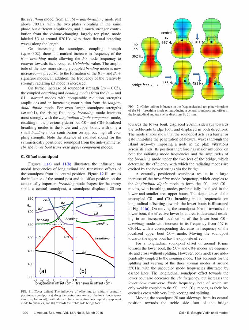
Figures 11(a) and 11(b) illustrates the influence on
modal frequencies of longitudinal and transverse offsets of
the soundpost from its central position. Figure 12 illustrates
the influence of the sound post and its offset position on the
acoustically important breathing mode shapes: for the empty
shell, a central soundpost, a soundpost displaced 20 mm
towards the lower bout, displaced 20 mm sideways towards
the treble-side bridge foot, and displaced in both directions.
The mode shapes show that the soundpost acts as a barrier or
gate inhibiting the penetration of flexural waves through the
island area—by imposing a node in the plate vibrations
across its ends. Its position therefore has major influence on
both the radiating mode frequencies and the amplitudes of
the breathing mode under the two feet of the bridge, which
determine the efficiency with which the radiating modes are
excited by the bowed strings via the bridge.
A centrally positioned soundpost results in a large
increase of the breathing mode frequency, which couples to
the longitudinal dipole mode to form the C0� and C0þmodes, with breathing modes preferentially localized in the
lower and smaller area upper bouts. The dependence of the
uncoupled C0� and C0þ breathing mode frequencies on
longitudinal offsetting towards the lower bouts is illustrated
in Fig. 11(a). On moving the soundpost 20 mm towards the
lower bout, the effective lower bout area is decreased result-
ing in an increased localization of the lower-bout C0�breathing mode with increase in its frequency from 567 to
620 Hz, with a corresponding decrease in frequency of the
localized upper bout C0þ mode. Moving the soundpost
towards the upper bout has the opposite effect.
For a longitudinal soundpost offset of around 10 mm
towards the lower bout, the C0� and C0þ modes are degener-
ate and cross without splitting. However, both modes are inde-
pendently coupled to the bending mode. This accounts for the
splitting and veering of the three normal modes at around
550 Hz, with the uncoupled mode frequencies illustrated by
dashed lines. The longitudinal soundpost offset towards the
lower bout also decreases the cbr frequency, but increases the
lower bout transverse dipole frequency, both of which are
only weakly coupled to the C0� and C0þ modes, as their fre-
quencies cross with very little veering and splitting.
Moving the soundpost 20 mm sideways from its central
position towards the treble side foot of the bridge
FIG. 11. (Color online) The influence of offsetting an initially centrally
positioned soundpost (a) along the central axis towards the lower bouts (pos-
itive displacement), with dashed lines indicating uncoupled component
mode frequencies, and (b) towards the treble side bridge foot.
FIG. 12. (Color online) Influence on the frequencies and top plate vibrations
of the b1� breathing mode on introducing a central soundpost and offset in
the longitudinal and transverse directions by 20 mm.
1220 J. Acoust. Soc. Am., Vol. 137, No. 3, March 2015 Colin E. Gough: Violin shell modes
significantly reduces the soundpost barrier constraint, allow-
ing the lower bout vibrations to penetrate more easily into
the upper bouts through the bass-side of the island area. As a
result, the localized bout C0� and C0þ modes are trans-
formed into the more familiar breathing and longitudinal
dipole modes, as illustrated in Fig. 12. Because the lower
bout breathing mode can now penetrate more readily through
the island area, its vibrating area is increased resulting in a
significant decrease in frequency from the central soundpost
position from 567 to 453 Hz.
Such a mode is regularly observed in experimental
modal analysis measurements and was first reported by
Runnemalm et al.30 in holographic measurements, with
central waist displacements interpreted using a cylindrical
shell model intersected by two and three nodal planes with a
roughly elliptical transverse cross-section parallel to the
bridge.31
For such a large offset, the breathing mode crosses that
of the less strongly perturbed cbr mode. The veering and
splitting of the modes at frequencies where they would oth-
erwise have crossed demonstrates the existence of coupling
between the two modes. The transverse soundpost offset
therefore results in the cbr mode acquiring a breathing mode
component allowing it to contribute to the radiated sound.
The intensity of radiated sound will be very sensitive to both
the soundpost transverse offset distance and the relative
separation of the breathing and cbr mode frequencies. This
explains why very little sound is radiated by the CBRsignature mode in many instruments, but is significant in
others—notably in the fine sounding Titian Stradivari
violin.14
On combining the two offsets, the “soundpost barrier” is
further decreased allowing an increased penetration of the
breathing mode into the upper bout, as illustrated in Fig. 12.
This has little effect on the breathing mode frequency, only
decreasing from 453 to 451 Hz. However, just as important
as the frequency of the breathing mode is the strength with
which the coupled modes can be excited by the horizontal
component of the bowing. This is dependent on the ampli-
tudes and asymmetry of the perturbed breathing mode shape
across the two feet of the asymmetrically rocking bridge,
which are strongly dependent on the position of the sound-
post relative to the treble-side bridge foot.
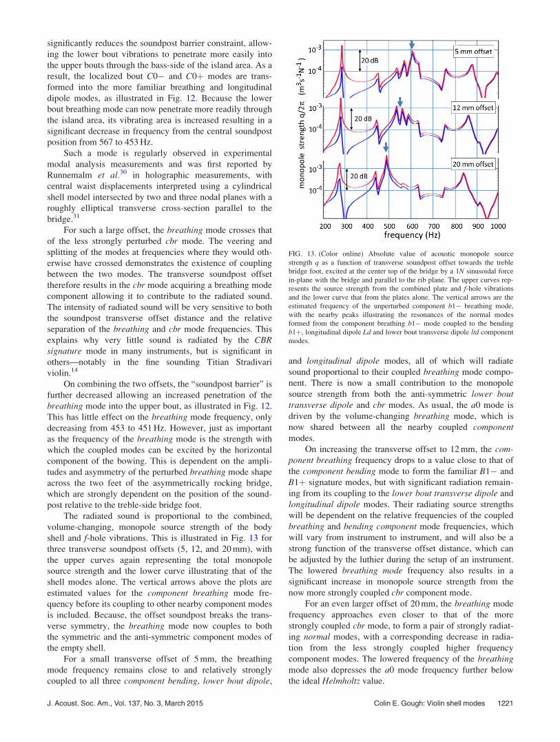
The radiated sound is proportional to the combined,
volume-changing, monopole source strength of the body
shell and f-hole vibrations. This is illustrated in Fig. 13 for
three transverse soundpost offsets (5, 12, and 20 mm), with
the upper curves again representing the total monopole
source strength and the lower curve illustrating that of the
shell modes alone. The vertical arrows above the plots are
estimated values for the component breathing mode fre-
quency before its coupling to other nearby component modes
is included. Because, the offset soundpost breaks the trans-
verse symmetry, the breathing mode now couples to both
the symmetric and the anti-symmetric component modes of
the empty shell.
For a small transverse offset of 5 mm, the breathing
mode frequency remains close to and relatively strongly
coupled to all three component bending, lower bout dipole,
and longitudinal dipole modes, all of which will radiate
sound proportional to their coupled breathing mode compo-
nent. There is now a small contribution to the monopole
source strength from both the anti-symmetric lower bouttransverse dipole and cbr modes. As usual, the a0 mode is
driven by the volume-changing breathing mode, which is
now shared between all the nearby coupled componentmodes.
On increasing the transverse offset to 12 mm, the com-ponent breathing frequency drops to a value close to that of
the component bending mode to form the familiar B1� and
B1þ signature modes, but with significant radiation remain-
ing from its coupling to the lower bout transverse dipole and
longitudinal dipole modes. Their radiating source strengths
will be dependent on the relative frequencies of the coupled
breathing and bending component mode frequencies, which
will vary from instrument to instrument, and will also be a
strong function of the transverse offset distance, which can
be adjusted by the luthier during the setup of an instrument.
The lowered breathing mode frequency also results in a
significant increase in monopole source strength from the
now more strongly coupled cbr component mode.
For an even larger offset of 20 mm, the breathing mode
frequency approaches even closer to that of the more
strongly coupled cbr mode, to form a pair of strongly radiat-
ing normal modes, with a corresponding decrease in radia-
tion from the less strongly coupled higher frequency
component modes. The lowered frequency of the breathingmode also depresses the a0 mode frequency further below
the ideal Helmholtz value.
FIG. 13. (Color online) Absolute value of acoustic monopole source
strength q as a function of transverse soundpost offset towards the treble
bridge foot, excited at the center top of the bridge by a 1N sinusoidal force
in-plane with the bridge and parallel to the rib plane. The upper curves rep-
resents the source strength from the combined plate and f-hole vibrations
and the lower curve that from the plates alone. The vertical arrows are the
estimated frequency of the unperturbed component b1� breathing mode,
with the nearby peaks illustrating the resonances of the normal modes
formed from the component breathing b1� mode coupled to the bending
b1þ, longitudinal dipole Ld and lower bout transverse dipole ltd component
modes.
J. Acoust. Soc. Am., Vol. 137, No. 3, March 2015 Colin E. Gough: Violin shell modes 1221
The very strong influence of the transverse soundpost
offset on the relative radiative strength of the various compo-
nent modes contributing to the sound and hence quality of an
instrument in the signature mode region is consistent with
earlier measurements by McLennan.32
The above analysis illustrates the importance of the
soundpost in controlling the sound of the violin and, by
implication, all instruments of the violin family sharing a
similar geometry. However, because of the significant varia-
tion in component mode frequencies among even the finest
violins, it is difficult to understand why there should neces-
sarily be a “correct” position for the soundpost common to
all violins—or why this should be in the same relative posi-
tion for other instruments of the violin family with very dif-
ferent dimensions and relative mode frequency placing. Even
for the finest instruments, quite small soundpost adjustments
are often used to optimize the sound. It may well be that
much larger than traditional soundpost adjustments could
compensate, at least in part, for lesser quality violins and
other instruments of the violin family. However, structural
stability will always provide a limitation on the distance the
soundpost can safely be moved away from the bridge sup-
porting the large downward forces of the stretched strings.
VII. THE BASS-BAR
The offset bass-bar results in a similar, but weaker, sym-
metry breaking constraint to that of the soundpost, as
described in the earlier paper on individual plate vibrations.3
The bass-bar acts as a strengthening beam inhibiting bending
along its length. Computations show that this can either
enhance the penetration of lower bout vibrations across the
island area into the upper bouts or act as a barrier tending to
localize higher frequency plate vibrations to one or other
side of its length.
Because the intention is to understand the role of the
bass-bar rather than to make predictions for a specific profile
along its length, a very simple shape was used for the com-
putations, with the upper surface profile determined by the
longitudinal arching of the plates and a straight lower surface
with a height of 6 mm at the center of the violin. A density
of 460 kg m�3 was assumed with mass 2.8 g and an isotropic
elastic modulus 2 GPa, which could be varied by an order of
magnitude above and below unity, to mimic its likely influ-
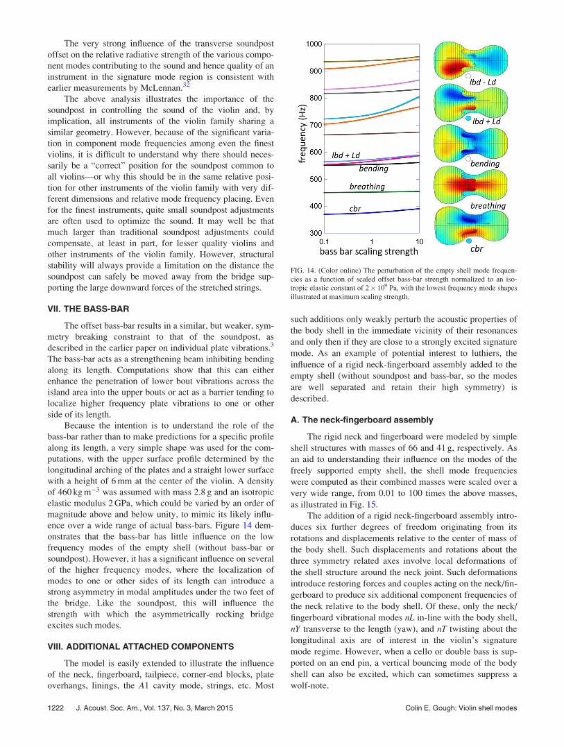
ence over a wide range of actual bass-bars. Figure 14 dem-
onstrates that the bass-bar has little influence on the low
frequency modes of the empty shell (without bass-bar or
soundpost). However, it has a significant influence on several
of the higher frequency modes, where the localization of
modes to one or other sides of its length can introduce a
strong asymmetry in modal amplitudes under the two feet of
the bridge. Like the soundpost, this will influence the
strength with which the asymmetrically rocking bridge
excites such modes.
VIII. ADDITIONAL ATTACHED COMPONENTS
The model is easily extended to illustrate the influence
of the neck, fingerboard, tailpiece, corner-end blocks, plate
overhangs, linings, the A1 cavity mode, strings, etc. Most
such additions only weakly perturb the acoustic properties of
the body shell in the immediate vicinity of their resonances
and only then if they are close to a strongly excited signature
mode. As an example of potential interest to luthiers, the
influence of a rigid neck-fingerboard assembly added to the
empty shell (without soundpost and bass-bar, so the modes
are well separated and retain their high symmetry) is
described.
A. The neck-fingerboard assembly
The rigid neck and fingerboard were modeled by simple
shell structures with masses of 66 and 41 g, respectively. As
an aid to understanding their influence on the modes of the
freely supported empty shell, the shell mode frequencies
were computed as their combined masses were scaled over a
very wide range, from 0.01 to 100 times the above masses,
as illustrated in Fig. 15.
The addition of a rigid neck-fingerboard assembly intro-
duces six further degrees of freedom originating from its
rotations and displacements relative to the center of mass of
the body shell. Such displacements and rotations about the
three symmetry related axes involve local deformations of
the shell structure around the neck joint. Such deformations
introduce restoring forces and couples acting on the neck/fin-
gerboard to produce six additional component frequencies of
the neck relative to the body shell. Of these, only the neck/
fingerboard vibrational modes nL in-line with the body shell,
nY transverse to the length (yaw), and nT twisting about the
longitudinal axis are of interest in the violin’s signature
mode regime. However, when a cello or double bass is sup-
ported on an end pin, a vertical bouncing mode of the body
shell can also be excited, which can sometimes suppress a
wolf-note.
FIG. 14. (Color online) The perturbation of the empty shell mode frequen-
cies as a function of scaled offset bass-bar strength normalized to an iso-
tropic elastic constant of 2� 109 Pa, with the lowest frequency mode shapes
illustrated at maximum scaling strength.
1222 J. Acoust. Soc. Am., Vol. 137, No. 3, March 2015 Colin E. Gough: Violin shell modes

As described below, for typical neck-fingerboard
masses, the only significant effect is to introduce a slight
decrease in the frequency of the bending mode of the shell
relative to that of the body shell alone and to introduce the
two additional nL and nY modes below or around the A0
resonance. The two modes can introduce substructure below
or even a splitting of the A0 mode.
For a very light added mass, most of the rotational
energy is confined to the neck-fingerboard vibrations, with
uncoupled frequencies varying asffiffiffiffiffiffiffiffiG=I
p, where G is the
relevant torsional spring constant introduced by shell defor-
mations and I (proportional to mass) the moment of inertia
of the neck-fingerboard assembly for rotation about the neck
joint for each of the three orthogonal directions. The rigid
neck-fingerboard vibrations therefore decrease in frequency
with increasing mass crossing the frequencies of many of the
higher order modes. This results in the familiar veering and
splitting of the normal modes describing their coupled vibra-
tions, as illustrated in Fig. 15.
Acoustically, the symmetric nL neck mode is the most
important vibrational mode of the neck assembly. This mode
is strongly coupled to the empty shell bending mode to form
a split pair of strongly veering normal modes describing
their in- and out-of-phase vibrations about the neck joint.
This is highlighted by the thickened lines superimposed on
the computed data in Fig. 15. Their coupling results in a
decrease of the initial empty shell bending mode frequency
on increasing mass, with the strongly perturbed bendingmode transforming into the longitudinal nL neck mode at
typical neck/fingerboard masses. However, such rotations
retain contributions from the bending mode of the body shell
bL. For very heavy masses, there is little motion of the neck-
fingerboard. The frequency therefore approaches that of the
rigidly supported neck, with now only the violin shell rotat-
ing about the neck joint at a frequency now determined byffiffiffiffiffiffiffiffiffiG=Is
p, where Is is the moment inertia of the empty shell.
Similarly, as the nL neck vibrations decrease in fre-
quency from their initially high value at small masses, they
cross other symmetric modes to which they are coupled by
varying amounts. This again results in weak veering and
splitting of the upper normal mode branch, again highlighted
by the superimposed thick lines. On approaching the initial
bending mode frequency, the upper normal mode branch is
smoothly transformed from its initial nL character into that
of a breathing mode, with a frequency slightly below that of
the empty shell alone for typical neck-fingerboard masses.
The transverse yaw nY neck mode exhibits a similar
behavior, but is less strongly coupled to any of the lower fre-
quency modes and then only to antisymmetric modes. The
nT neck twisting mode is at a considerably higher frequency
because of its significantly smaller moment of inertia. It
interacts strongly with the higher frequency fundamental
twisting shell mode derived from the #1 free plate vibrations
twisting in the same way. The frequencies of the split pair
of twisting normal modes are indicated as nT� and nTþ in
Fig. 15.
Neither the nY nor nT neck-fingerboard modes have any
significant influence on the breathing mode, so have a negli-
gible influence on the acoustics of an instrument. For large
masses, their frequencies approach those of the shell rotating
about the rigidly supported neck. The relative insensitivity
of mode frequencies to being supported by a rigidly held
neck suggests this might be a useful way of holding an
instrument to derive easily reproducible characterization
measurements, especially when laser measurements are
involved.
B. Coupled component vibrations
The influence of the non-radiating vibrational modes of
the fingerboard, neck, tailpiece, A1 cavity resonance, and
strings can easily be understood by adding horizontal lines at
their individual uncoupled resonant frequencies in figures
like Fig. 9. Whenever, such lines cross the frequencies of the
shell modes, any coupling between them will introduce addi-
tional veering and splitting of the normal mode frequencies
describing their coupled in- and out-of phase vibrations. All
such additional resonances will, in principle, contribute to
the admittance experienced by the vibrating strings at the
bridge and hence playability of the instrument. Acoustically,
the only resonances that are important in the signature mode
regime are those that couple to the breathing mode compo-
nent of strongly radiating modes, such as the B1� and B1þmodes. In general, weakly coupled modes will introduce
small resonant features superimposed on the main signature
mode resonances, but can split the main resonances when
their frequencies are closely coincident—with the splitting
from over-strong coupling to the bowed vibrating strings in
particular giving rise to the wolf note (Gough33).
FIG. 15. (Color online) The computed influence on the frequencies of the
empty body shell (no soundpost or bass-bar) of adding a rigid neck-
fingerboard assembly, as a function of its combined mass varied by a factor
100 above and below a typical neck and fingerboard mass of mass of 66 and
41 g, respectively. The superimposed thicker lines illustrate the strong veer-
ing and splitting of the normal modes resulting from the in- and out-of phase
vibrations of the component neck and body-shell bending vibrations and the
weaker veering and splitting of their frequencies on crossing the frequencies
of other less strongly coupled shell modes.
J. Acoust. Soc. Am., Vol. 137, No. 3, March 2015 Colin E. Gough: Violin shell modes 1223
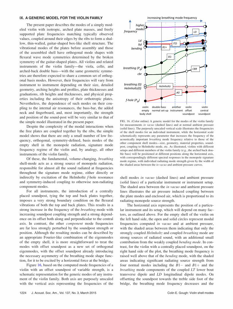
IX. A GENERIC MODEL FOR THE VIOLIN FAMILY
The present paper describes the modes of a simply mod-
eled violin with isotropic, arched plate masses, and freely
supported plate frequencies matching typically observed
values, coupled around their edges by the ribs to form a shal-
low, thin-walled, guitar-shaped box-like shell structure. The
vibrational modes of the plates before assembly and those
of the assembled shell have orthogonal mode shapes with
flexural wave mode symmetries determined by the broken
symmetry of the guitar-shaped plates. All violins and related
instruments of the violin family—the viola, cello, and
arched-back double bass—with the same geometric symme-
tries are therefore expected to share a common set of orthog-
onal basis modes. However, their frequencies will vary from
instrument to instrument depending on their size, detailed
geometry, arching heights and profiles, plate thicknesses and
graduations, rib heights and thicknesses, and physical prop-
erties including the anisotropy of their orthotropic plates.
Nevertheless, the dependence of such modes on their cou-
pling to the internal air resonances, the bass-bar, the added
neck and fingerboard, and, most importantly, the strength
and position of the sound-post will be very similar to that of
the simple model illustrated in the present paper.
Despite the complexity of the modal interactions when
the free plates are coupled together by the ribs, the simple
model shows that there are only a small number of low fre-
quency, orthogonal, symmetry-defined, basis modes of the
empty shell in the monopole radiation, signature mode
frequency regime of the violin and, by analogy, all other
instruments of the violin family.
Of these, the fundamental, volume-changing, breathingshell-mode acts as a strong source of monopole radiation,
responsible for almost all the sound radiated at frequencies
throughout the signature mode regime, either directly or
indirectly by excitation of the Helmholtz f-hole resonance
and symmetry-induced coupling to otherwise non-radiating
component modes.
For all instruments, the introduction of a centrally
placed soundpost, tying the top and back plates together,
imposes a very strong boundary condition on the flexural
vibrations of both the top and back plates. This results in a
strong increase in the frequency of the breathing mode with
increasing soundpost coupling strength and a strong depend-
ence on its offset both along and perpendicular to the central
axis. In contrast, the other component mode frequencies
are far less strongly perturbed by the soundpost strength or
position. Although the resulting modes can be described by
an appropriate Fourier-like combination of the eigenmodes
of the empty shell, it is more straightforward to treat the
modes with offset soundpost as a new set of orthogonal
eigenmodes, with the offset soundpost already introducing
the necessary asymmetry of the breathing mode shape func-
tion, for it to be excited by a horizontal force at the bridge.
Figure 16, based on the computed mode frequencies of a
violin with an offset soundpost of variable strength, is a
schematic representation for the generic modes of any instru-
ment of the violin family. Both axis are purposely unscaled
with the vertical axis representing the frequencies of the
shell modes in vacuo (dashed lines) and ambient pressure
(solid lines) of a particular instrument or instrument setup.
The shaded area between the in vacuo and ambient pressure
lines illustrates the air pressure induced coupling between
the plate modes and enclosed air, which is proportional to its
radiating monopole source strength.
The horizontal axis represents the position of a particu-
lar instrument and its setup, which will depend on many fac-
tors, as outlined above. For the empty shell of the violin on
the left hand side, the open and solid circles represent modal
frequencies computed in vacuo and at ambient pressure,
with the shaded areas between them indicating that only the
strongly coupled Helmholtz and coupled breathing mode are
strong sources of radiated sound, with an additional small
contribution from the weakly coupled bending mode. In con-
trast, for the violin with a centrally placed soundpost, on the
right hand side of the plot, the breathing mode frequency is
raised well above that of the bending mode, with the shaded
areas indicating significant radiating source strength from
four normal modes including the B1� and B1þ and the
breathing mode components of the coupled LT lower bout
transverse dipole and LD longitudinal dipole modes. On
offsetting the soundpost towards the treble side foot of the
bridge, the breathing mode frequency decreases and the
FIG. 16. (Color online) A generic model for the modes of the violin family
for measurements in vacuo (dashed lines) and at normal ambient pressure
(solid lines). The purposely unscaled vertical scale illustrates the frequencies
of the shell modes for an individual instrument, while the horizontal scale
schematically represents any parameter that increases the frequency of the
acoustically important breathing mode frequency relative to those of the
other component shell modes—size, geometry, material properties, sound-
post, coupling to Helmholtz mode, etc. As illustrated, violins with different
setups and different members of the violin family (e.g., the arched back dou-
ble bass) will be positioned at different positions along the horizontal axis,
with correspondingly different spectral responses in the monopole signature
mode regime, with individual radiating mode strength given by the width of
the shaded areas between the in vacuo and ambient pressure curves.
1224 J. Acoust. Soc. Am., Vol. 137, No. 3, March 2015 Colin E. Gough: Violin shell modes
instrument’s position moves to the left with most of the radi-
ation now from the B1þ and B1� modes with a small contri-
bution from the LD mode.
Different violins and different members of the violin
family will have different positions along the horizontal axis
determined by their different shapes, sizes, physical proper-
ties and setups. For example, measurements on the arched
back double bass show its position to be far to the left of the
plot, with the A0 and breathing modes dominating the radi-
ated sound. Other instruments of the violin family could be
positioned anywhere along the horizontal axis depending on
many factors, illustrated for example by “another
instrument.” In all cases the strongest influence on the radi-
ated sound will be the frequency of the breathing mode in
relation to the other component shell modes, with its fre-
quency strongly dependent on soundpost strength and both
longitudinal and transverse offset.
ACKNOWLEDGMENTS
I am grateful for valuable discussions with colleagues at
the annual Oberlin Violin Acoustics workshops including
the distinguished violin makers Joseph Curtin, George
Stoppani, and Sam Zygmuntowicz and acousticians Evan
Davis and George Bissinger. Additional helpful discussions
with Jim Woodhouse are also gratefully acknowledged.
1L. Cremer, The Physics of the Violin, translated by J. S. Allen (MIT Press,
Cambridge, 1983), pp. 1–450.2Research Papers in Violin Acoustics 1975–1993, edited by C. Hutchins
and V. Benade (Acoustical Society of America, Woodbury, NY, 1997),
Vols. 1, pp. 1–655, and 2, pp. 659–1312.3C. Gough, “Violin plate modes,” J. Acoust. Soc. Am. 137(1), 139–153
(2015).4COMSOL Multiphysics 3.5, Structural mechanics, shell structure, finite
element software.5G. Knott, “A modal analysis of the violin,” Master’s thesis, Naval
Postgraduate School, Monterey, CA (1987) (reprinted as paper 54 in Ref.
2, pp. 497–549).6G. Roberts, “Finite element analysis of the violin,” Ph.D. thesis,
University College, Cardiff, Wales (1986) (selected sections published as
paper 16, in Ref. 2, pp. 575–590).7J. Bretos, C. Santamaria, and J. A. Moral, “Vibrational patterns and fre-
quency responses of the free plates and box of a violin obtained by finite
element analysis,” J. Acoust. Soc. Am. 105, 1942–1950 (1999).8O. Rogers and P. Anderson, “Finite element analysis of violin corpus,”
Catgut Acoust. J. 4, 13–26 (2001).9G. Bissinger, “Modal analysis of a violin octet,” J. Acoust. Soc. Am. 113,
2105–2113 (2003).
10G. Bissinger, “Structural acoustics of good and bad violins,” J. Acoust.
Soc. Am. 124, 1764–1773 (2008).11C. Gough, “A finite element approach towards understanding violin struc-
tural modes,” J. Acoust. Soc. Am. 127, 1791 (2010).12C. Gough, “Vibrational modes of the violin family,” in Proceedings of
SMAC 2013, Stockholm, Sweden, pp. 66–74.13C. Gough, “A generic model for instruments of the violin family,” Proc.
Inst. Acoust. 35(1), 2015–2525 (2013).14S. Zygmuntowicz and G. Bissinger, “Strad3D—A unified enquiry,” in a 2
DVD ROM set (Violin Society of America, Poughkeepsie, NY, 2009).15C. M. Hutchins, “Physics of violins,” Sci. Am. 207, 78–92 (1962).16J. Curtin, “Tap tones and weights of old Italian violin tops,” Violin Soc.
Am. Papers 20(2), 162–174 (2006).17N. E. Molin, L.-E. Lindgren, and E. V. Jansson, “Parameters of violin
plates and their influence on the plate modes,” J. Acoust. Soc. Am. 83(1),
281–291 (1988).18E. Jansson, N.-E. Molin, and H. Sundin, “Resonances of a violin body
studied by hologram interferometry and acoustical methods,” Phys. Scr. 2,
243–256 (1970).19M. Schleske, “Eigenmodes of vibration in the working process of a vio-
lin,” Catgut Acoust. Soc. 3, 1–8 (1996).20C. E. Gough, “Computed cavity-air modes of le Gruere violin and cou-
pling to corpus modes,” J. Acoust. Soc. Am. 127, 1792 (2010).21G. Bissinger, “Wall compliance and violin cavity modes,” J. Acoust. Soc.
Am. 113, 1718–1723 (2003).22G. Weinreich, C. Holmes, and M. Mellody, “Air-wood coupling and the
Swiss-cheese violin,” J. Acoust Soc. Am. 108, 2389–2402 (2000).23A. W. Brown, “Documentation of double bass plate modes using the laser
vibrometer bass,” in Proceedings of ISMA 2004, Nara (2004), pp.
344–347.24A. Askenfelt, “Double bass,” in The Science of Musical Instruments,
edited by T. D. Rossing (Springer, New York, 2010), Chap. 14, pp.
259–278.25C. Gough, “Acoustic characterisation of violin family signature modes by
internal cavity measurements,” in Proceedings of SMAC 2013, Stockholm,
Sweden (2013), pp. 75–81.26F. V. Savart, “M�emoires sur le construction des Instruments �a Cordes et �a
Archet” (“Submissions on the construction of string instruments and
bow”) (Deterville, Paris, 1819).27J. C. Schelleng, “The action of the soundpost,” Catgut Soc. Newsletter 16,
11–15 (1971).28G. Weinreich, “Sound hole sum rule and dipole moment of the violin,”
J. Acoust. Soc. Am. 77(2), 710–718 (1985).29G. Bissinger, E. G. Williams, and N. Valdivi, “Violin f-hole contribution
to far-field radiation via patch near-field acoustical holography,”
J. Acoust. Soc. Am. 121, 3899–3906 (2007).30A. Runnemalm, N.-E. Molin, and E. Jansson, “On operating deflection
shapes of the violin body including in-plane motions,” J. Acoust. Soc.
Am. 107, 3452–3459 (2000).31T. D. Rossing, N.-E. Molin, and A. Runnemalm, “Modal analysis of violin
bodies viewed as three-dimensional structures,” J. Acoust, Soc. Am. 114,
2438 (2003).32J. McLennan, http://newt.phys.unsw.edu.au/music/people/mclennan_
soundpost.html (Last viewed December 1, 2014).33C. E. Gough, “The resonant response of a violin G-string and the excita-
tion of the wolf-note,” Acustica 44(2), 113–123 (1980).
J. Acoust. Soc. Am., Vol. 137, No. 3, March 2015 Colin E. Gough: Violin shell modes 1225