a view on the cause of parachute instability
DESCRIPTION
pstTRANSCRIPT

NSWC TR 83-28
A VIEW ON THE CAUSE OF PARACHUTE INSTABILITY
BY W. P. LUDTKE
UNDERWATER SYSTEMS DEPARTMENT
10 MAY 1983
Distribution limited to U. S. Government agencies only; Test and Evaluation. Statement applied 10 May 1983. Other requests for this document must be referred to NSWC, Code U13.
t A S V V i
NAVAL SURFACE WEAPONS CENTER Dahigren, Virginia 22448 • Silver Spring, Maryland 20910
TL7S1
.L822
1983

LINDA Science

UNCLASSIFIED S E C U R I T Y C L A S S I F I C A T I O N O F T H I S P A G E (1«!»n Dmte En tired)
REPORT DOCUMENTATION PAGE READ INSTRUCTIONS BEFORE COMPLETING FORM
1 R E P O R T N U M B E R
NSWC TR 83-28 2. G O V T A C C E S S I O N NO. 3. R E C I P I E N T ' S C A T A L O G N U M B E R
4 T I T L E (and Subtitle) S. T Y P E O F R E P O R T ft P E R I O D C O V E R E D
A VIEW ON THE CAUSE OF PARACHUTE INSTABILITY t . P E R F O R M I N G O R G . R E P O R T N U M B E R
7. A U T H O R S ; ». C O N T R A C T O R G R A N T N U M B E R S
W. P. Ludtke 9. P E R F O R M I N G O R G A N I Z A T I O N N A M E A N D A D D R E S S
Naval Surface Weapons Center White Oak Silver Spring, Maryland 20910
10. P R O G R A M E L E M E N T . P R O J E C T , T A S K A R E A ft WORK U N I T N U M B E R S
64601N S0267-MW
11. C O N T R O L L I N G O F F I C E N A M E A N D A D D R E S S 12. R E P O R T D A T E
10 May 1983 11. N U M B E R O F P A G E S
44 U M O N I T O R I N G A G E N C Y N A M E » A D D R E S S f / / dlllerent 1 com Controlling Oil!CO) IS . S E C U R I T Y C L A S S , (ol thle report)
Unclassified 1S«. D E C L A S S I F I C A T I O N / D O W N G R A D I N G
S C H E D U L E
16. D I S T R I B U T I O N S T A T E M E N T (o 1 thh Report)
Distribution limited to U.S. Government agencies only; Test and Evaluation. Statement applied 10 May 1983. Other requests for this document must be referred to NSWC, Code U13.
17. D I S T R I B U T I O N S T A T E M E N T (ol the abetrecl entered In Block 20, II dlllerent Ire •at Report)
IB. S U P P L E M E N T A R Y N O T E S
19. K E Y W O R D S (Continue on reveree elde If neceeemry end Identify by block number)
Parachute Stability Disc-gap-band parachute Parafoil parachute Lift control
20. A B S T R A C T (Continue on reveree elde II neceeemry and Identity by MocJc number)
This report presents a theoretical discussion of the mechanism of parachute instability for the purpose of improving parachute technology. The theory is based upon considering the inflated canopy shape as a series of opposing airfoils which produce a destabilizing lift force. The methods by which several types of parachutes utilize lift control to provide stability are discussed together with a demonstration of lift control to stabilize the flat solid cloth types of parachutes.
DD , j NM73 1473 E D I T I O N O F I NOV 65 IS O B S O L E T E UNCLASSIFIED S / N 0 1 0 2 - L F - 0 1 4 - 6 6 0 1 » E C U « I T Y C L A M I U C A T I O N O F T H I S P A G E f W i . n Dmte Entered)

UNCLASSIFIED S E C U R I T Y C L A S S I F I C A T I O N O F T H I S P A G E ( W m i Dmlm E n l i t . J )
20. ABSTRACT (Cont.)
The thickness ratio and location aft of the airfoil-like shape leading for several paracute types, and shown true airfoils.
~XL15\ I Oq<\
of the maximum airfoil ordinate edge are analytically determined to be in reasonable agreement with
0102- LF. 0U- 6601 UNCLASSIFIED
S E C U R I T Y C L A S S I F I C A T I O N O F T H I S P A G E f W J i . n Dal. Enter.d)

NSWC TR 83-28
FOREWORD
This report presents a theoretical discussion of the mechanism of parachute instability for the purpose of improving parachute technology. The theory is based upon considering the inflated canopy shape as a series of opposing airfoils which produce a destabilizing lift force. The methods by which several types of parachutes utilize lift control to provide stability are discussed together with a demonstration of lift control to stabilize the flat solid cloth types of parachutes.
The thickness ratio and location of the maximum airfoil ordinate aft of the airfoil-like shape leading edge are analytically determined for several parachute types, and shown to be in reasonable agreement with true airfoils.
vsEOROE P. KALAF/ Head /Mine Warfare Division
i/ii
LINDA HALL LIBRARY KAN6AS CITY, MO

NSWC TR 83-28
CONTENTS
INTRODUCTION
THE STABILITY PROBLEM
THE INFLATED CANOPY AS AN AIRFOIL-LIKE SHAPE
COMMENTS ON OTHER AIRFOIL-LIKE SHAPES RELATED TO PARACHUTES
BIBLIOGRAPHY
DEFINITIONS
NOMENCLATURE
iii/iv
NSWC TR 83-28
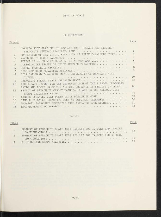
ILLUSTRATIONS
Figure P a§ e
1 TORPEDO SIDE SLAP DUE TO LOW ALTITUDE RELEASE AND RINGSLOT PARACHUTE NEUTRAL STABILITY ZONE 2
2 COMPARISON OF THE STATIC STABILITY OF THREE PARACHUTE TYPES. . . . 3 3 YAWED SOLID CLOTH PARACHUTE 4 4 EFFECT OF Act ON AIRFOIL ANGLE OF ATTACK AND LIFT 6 5 AIRFOIL-LIKE SHAPES OF GUIDE SURFACE PARACHUTES 7 6 REEFED "PARACHUTE GEOMETRY 8 7 DISC GAP BAND PARACHUTE ASSEMBLY 9 8 DISK GAP BAND PARACHUTE IN THE UNIVERSITY OF MARYLAND WIND
TUNNEL 1 0
9 PARACHUTE STEADY STATE INFLATED SHAPE 12 10 COORDINATE SYSTEM FOR THE DETERMINATION OF THE AIRFOIL THICKNESS
RATIO AND LOCATION OF THE AIRFOIL ORDINATE IN PERCENT OF CHORD . . 14 11 EFFECT OF PARACHUTE CANOPY MAINSEAM SHAPE ON THE AIRFOIL-LIKE
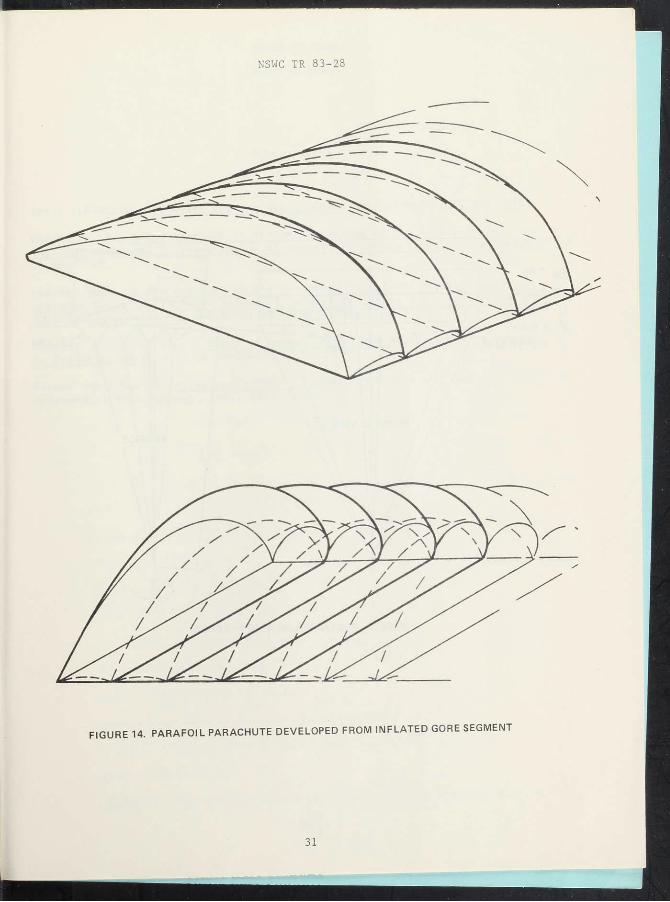
SHAPE THICKNESS RATIO 2 9 12 SINGLE INFLATED FLAT SOLID CLOTH PARACHUTE GORE 30 13 SINGLE INFLATED PARACHUTE GORE AT CONSTANT THICKNESS 30 14 PARAFOIL PARACHUTE DEVELOPED FROM INFLATED GORE SEGMENT 31 15 RECTANGULAR WING PARAFOIL 32
TABLES
Table
1 SUMMARY OF PARACHUTE SHAPE TEST RESULTS FOR 12-GORE AND 16-GORE CONFIGURATIONS 1 3
2 SUMMARY OF PARACHUTE SHAPE TEST RESULTS FOR 24-GORE AND 30-G0RE CONFIGURATIONS 1 3
3 AIRFOIL-LIKE SHAPE ANALYSIS 21
v/vi

NSWC TR 83-28
INTRODUCTION
The purpose of this paper is to present what the author believes to be a new view on the cause of parachute instability and a method of stability control based upon a relatively minor change in canopy configuration. This presentation is not intended as a rigorous study of parachute instability, but rather sets forth the author's observations on stability and their application to stability control. The hypothesis presented is that instability is the result of producing a side force which is due to the inflated canopy shape. The inflated canopy shape can be modified to reduce the destabilizing side force and thereby improve the stability of the parachute. A mechanism for the explanation of parachute instability is proposed, and the successful results of wind tunnel experiments to demonstrate the hypothesis are included.
The instability mechanism was derived from observation of solid cloth parachutes in the inflating, fully inflated, and reefed conditions. A fully inflated solid cloth parachute canopy can be generated by revolving an airfoil-like shape with a flat lower surface and a cambered upper surface about the parachute centerline at an angle of attack. This airfoil-like shape produces destabilizing aerodynamic side forces. In reefed and inflating parachutes, an airfoil-like shape is also present, but oriented with the trailing edge facing the approaching flow. The inefficient use of the airfoil-like shape in inflating and reefed parachutes is responsible for the parachute stability since it minimizes the destabilizing side forces. As a means of demonstration, unstable flat circular parachute models were modified, by the addition of a cylindrical section ahead of the canopy hem, to produce an airfoil-like section with the trailing edge of the section oriented into the approaching flow. These models were tested in a wind tunnel and demonstrated exceedingly improved stability.
THE STABILITY PROBLEM
In the 19601s, the Naval Surface Weapons Center (NAVSWC) was engaged in experimentation with a retardation system for an aircraft-launched torpedo. In low level delivery, the axis of the torpedo was yawed to an unacceptable angle from the trajectory. Analysis showed that the stability of the ringslot parachute was responsible. The parachute, due to its weight, would trim below the flight path causing the store to assume a nose high attitude which resulted in an unacceptable impact tail slap as shown in Figure 1. At higher release altitudes, the impact angle of the assembly increased to a point where the parachute was above the torpedo and the off axis effect was not s ignificant.

NSWC TR 83 - 28
F I G U R E 1. TORPEDO SIDE SLAP DUE TO LOW A L T I T U D E R E L E A S E AND R I N G S L O T P A R A C H U T E N E U T R A L S T A B I L I T Y ZONE
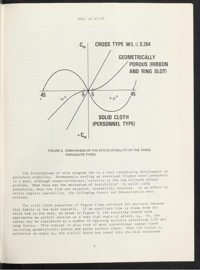
The static stability of three parachute types is illustrated in Figure 2. The low angle neutral stability zone of the geometrically porous canopies was the cause of the excessive off trajectory impact angles. The long period of oscillation, due to lack of restoring moments, gave time for the inertia of the system to respond to the off axis drag force. Solutions to this problem were to use a completely stable parachute such as a guide surface type (Cross type parachutes were still in the future), a cluster of small parachutes build an oversized geometrically porous canopy and permanently reef it to obtain stability, or put the burden on the weapon designer. Guide surface canopies were tested and provided excellent two-body stability, but were too bulky for the available volume. While the guide surface canopC gave excellent two-body stability, it did oscillate at a high frequency which' reduced the response time of the system, which demonstrates that stability and lack of oscillation are not necessarily the same. Clusters of three small ringslot parachutes had inflation problems so the final solution was a permanently reefed oversize ribbon parachute.
2
NSWC TR 83 - 28
F I G U R E 2. COMPARISON OF THE S T A T I C S T A B I L I T Y OF THE T H R E E P A R A C H U T E T Y P E S
SOLID CLOTH (PERSONNEL TYPE)
CROSS TYPE W/L< 0.264
GEOMETRICALLY POROUS (RIBBON AND RING SLOT)
The frustrations of this program led to a very interesting development m parachute stability. Permanently reefing an oversized (higher cost) parachute is a poor, although state-of-the-artsolution to the low altitude attack problem. What then was the mechanism of instability? In solid cloth parachutes, when the flow was attached, instability resulted. In an effort to better explain instability, the following theory and demonstration were evolved.
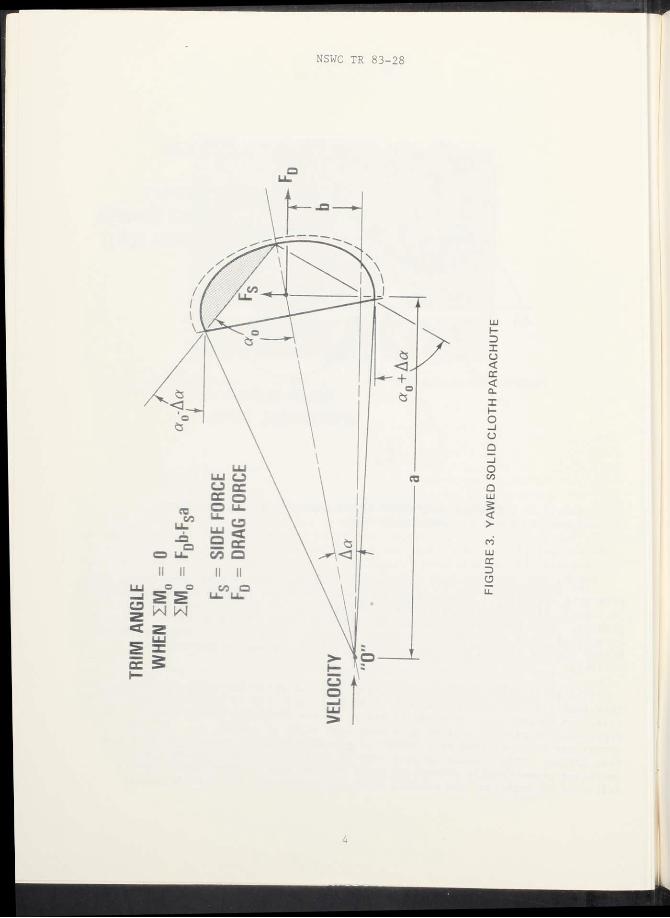
The solid cloth parachute of Figure 2 was selected for analysis because this family is the most unstable. If an auxiliary line is drawn from the skirt hem to the vent, as shown in Figure 3, the resulting shaded area approaches an airfoil section at a very high angle of attack, aD. So, the canopy may be considered as a number of opposing airfoils possessing lift and drag forces. This concept is also true of most conventional canopy types including geometrically porous and guide surface types. When the canopy is deflected an angle Aa, the airfoil which has yawed into the wind decreases
3
NSWC TR 83-28

NSWC TR 83 - 28
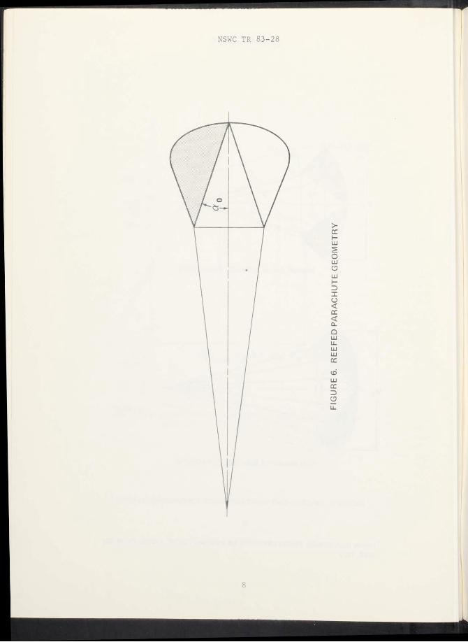
its angle of attack to a0-Aa, and the opposing airfoil increases its angle of attack to a0+Aa. The general variation of lift coefficient with angle of attack for this type of airfoil is shown in Figure 4. The high aQ angle is in the stall region of the airfoil. The airfoil yax ed into the wind is actually coming out of stall while the opposing airfoil goes deeper into the stall. Therefore, the canopy continues to yaw until the moments about the point "0" in Figure 3 are zero and this is the trim angle. Geometrically porous parachutes control lift by venting the airfoil. Ribbed Guide Surface parachutes utilize the stability of cones and reduce lift by separating the flow early by distortion of the airfoil. Ribless Guide Surface parachutes vent at the maximum diameter to control lift together with reaction from the jets. The airfoil-like shape of the Ribless Guide Surface parachute is not as distorted as the ribbed version and would be expected to be slightly less stable, see Figure 5. This type of parachute is very similar in performance to the NAVSWC Elliptical parachute. Another clue came from reefed parachute configurations which are stable. If the same auxiliary line is drawn from the hem to vent of a reefed parachute the resulting shape, see Figure 6, is a clumsy airfoil-like shape with the trailing edge of the airfoil into the relative wind at an angle of attack. An airfoil in this position should have poor lift and high drag. Bad for airfoils, but good for parachutes.
As a demonstration of this idea, the parachute of Figure 7 was developed. The shaded reversed airfoil was accomplished by adding a cylindrical tube ahead of a standard unstable flat canopy. The tube was made so that it could be shortened by increments. Excellent stability with virtually no oscillation was obtained with all the tube elements removed down to the last increment. When the last increment was removed, the canopy became unstable and violently oscillated demonstrating the concept. The gaps were used to extend the airfoil-like shape without the use of added cloth, thereby keeping additional volume and cost to a minimum. Figure 8 shows the world's first Disc Gap Band parachute in the University of Maryland wind tunnel.
It can be concluded that stability control is basically lift control, and that the two apparent methods of accomplishing this: (a) stability through porosity as in geometrically porous canopies, or (b) stability through shape as in the guide surface canopies are just different approaches to lift control. Another theoretical factor that affects the magnitude of the lift force is the cloth airflow permeability. A cloth of zero permeability produces the maximum lift and therefore should be the most unstable. As cloth permeability is increased, stability should improve; however, at some limiting value of permeability, the canopy becomes subjected to squidding and becomes very stable. This is in agreement with experience.
THE INFLATED CANOPY AS AN AIRFOIL-LIKE SHAPE
The steady state canopy shape investigation presented methods for determing the inflated gore coordinates and angles and demonstrated that the steady state inflated gore mainseam shape of several parachute types consists of two elliptical sections of common major diameter, 2a, and different minor
5

NSWC TR 83 - 28
TO 22°
FIGURE 4. EFFECT OF Aa ON AIRFOIL ANGLE OF ATTACK
6

NSWC TR 83 - 28
R I B B E D GUIDE S U R F A C E P A R A C H U T E
R I B L E S S GUIDE S U R F A C E P A R A C H U T E
F I G U R E 5. A I R F O I L - L I K E SHAPES OF GUIDE S U R F A C E PARACHUTES . 1
11RWIN INDUSTR IES , R E C O V E R Y SYSTEMS DESIGNS GUIDE , AFFDL-TR-78 151
DEC. 1978
- =43% c
- = 15% c
= 48.5°
7


NSWC TR 83 - 28
diameters, b and b ' . 2 , 3 , 4 The generalized inflated gore mainseam is illustrated in Figure 9, and scale factors determining the inflated shape are shown in Tables 1 and 2. The canopy shapes used in this analysis permit the expression of the inflated shape as y=f(x) and the mainseam tangent slope angle S=f '(x).5j6 xhe analysis can also be accomplished from photography by means of descriptive geometry for other canopy styles.
With reference to the nomenclature of Figures 9 and 10 the airfoil-like shape may be determined.
1. Ratio of mouth diameter, dm, to inflated diameter, 2a:
Using the hem coordinates; x=N-b; y-dm/2
^Topping, A. D., et al., A Study of Canopy Shapes and Stresses for Parachutes in Steady Descent, WADC TR 55-294, Oct 1955.
3Ludtke, W. P., A New Approach to the Determination of the Steady-State Inflated Shape and Included Volume of Several Parachute Types, NOLTR 69-159, 11 Sep 1969.
4Ludtke, W. P., A New Approach to the Determination of the Steady-State Inflated Shape and Included Volume of Several Parachute Types in 24-Gore and 30-Gore Configurations, NOLTR 70-178, 3 Sep 1970.
5Ludtke, W. P., NOLTR 69-159.
6Ludtke, W. P., NOLTR 70-178.
11

NSWC TR 83 - 28
12

NSWC TR 83 - 28
T A B L E 1. SUMMARY OF P A R A C H U T E SHAPE T E S T R E S U L T S FOR 12-GORE AND 16-GORE CONF IGURAT IONS
Parachute Ho. oi Suepanuon Velocity Seal* Factor. K A i at Ratio
Type Goret Li«e Length 2* 2B 21 2a K b b' b b' inch** meh tp. 0 # d F
C. L a a a a a
Flat Circular 12 34 60 73 645 650 .856 .6116 8817 1 4932 16 34 60 73 663 669 820 .5558 9039 1 4597
10* E i n n M 12 34 100 147 663 652 881 6424 .8860 1.5284 Skin 16 34 17 26 664 640 765 5580 8502 1.4082
Elliptic*! 12 34 7S 110 916 £12 £ 6 2 6 9667 1 5283 Elliptic*! 16 34 17 26 876 .800 6169 8163 1.4332
HemitpharKaf 12 34 126 163 996 1.254 1.0006 9080 1.9086 HemitpharKaf 16 34 76 110 994 1 185 9129 9380 1.8509
Rmgalot 12 34 26 37 .607 .654 853 .6566 £735 1.530
16% G«xr>etT>C 12 34 100 147 .616 663 .922 .6566 .8735 1.530
I W n y 12 34 200 293 .637 686 .916 .6666 .8735 1.530 I W n y 16 34 25 37 .611 656 827 6004 8890 1 4894
16 34 100 147 .617 .664 864 .6004 £890 1 4894
16 34 200 2S3 646 .696 644 .6004 £ 8 9 0 1.4894
Ribbon 12 34 26 37 666 .632 859 .6558 £ 7 6 8 1£326
24% G n t n v t r k 12 34 100 147 .616 663 .837 .6558 £768 1.5326
Pocoeity 12 34 200 293 .632 .681 £ 7 7 .6558 .8768 1 6326 Pocoeity 16 34 25 37 603 .660 .797 £ 5 7 0 £ 5 7 8 1.4148
I S 34 100 147 .626 674 791 £570 £ 5 7 8 1.4148
16 34 200 293 .648 696 .781 £ 5 7 0 £ 5 7 8 1.4148
34 26 37 .710 £ 4 3 1.242 £867 1.2776 2.1643 W / L - .264 34 100 147 .787 .540 1.270 £867 1.2776 2-1643 W / L - .264
34 200 293 .716 £ 4 7 1 -285 £867 1.2776 2.1643
47 26 37 .769 .680 1.113 8494 1.2512 2.1006
47 100 147 .729 £ 5 7 1.205 £494 1.2512 2.1006
47 200 293 .776 £ 9 2 1.110 .6494 1.2512 2.1006
T A B L E 2. SUMMARY OF P A R A C H U T E SHAPE T E S T R E S U L T S FOR 24-GORE AND 3Q-GORE CONF IGURAT IONS
Paracnuta No. of Suapanfkm Velocity Scale Factor. K Aae* Ratio
Type Gorat Ltrta Lenytti mph <01 21 2 i N b b' b b' inches D. a a a a a
Flat Circular* 24 34 • 60 73 677 679 .795 £ 7 5 8 £ 1 2 6 1.3884 Flat Circular*
30 34 17 25 .668 669 £ 2 7 .6214 7806 1 4020
1 0 * Eitandarf* 24 34 100 147 .665 646 £34 .5949 .8771 1.4720
Skirt 30 34 17 25 650 633 £25 .6255 .7962 1.4127
24 34 25 37 £ 6 3 .665 £24 .5800 .9053 1.4853
24 34 100 147 680 .682 .819 .5800 .9053 1.4853
Poroul 24 34 200 293 .694 .696 £09 £ 8 0 0 .9053 1.4853 Poroul
30 34 25 37 677 676 .788 £ 8 0 0 .9053 1.4853
34 100 147 .684 .68S £ 0 2 £ 8 0 0 .9053 1 4853
30 34 200 293 .696 .699 £ 0 0 £ 8 0 0 .9053 1 4853
24 34 25 37 .671 .673 .770 £ 9 8 0 .8187 1.4187
24 34 100 147 .676 .678 £13 .5980 £ 1 8 7 1.4167
24 34 200 293 .687 .689 £ 0 4 £ 9 8 0 £187 1.4167
30 34 25 37 .655 .657 .782 .6021 .8463 1 4484
14 100 147 £ 6 9 .670 784 .6021 £463 1.4484
30 34 200 293 .677 .679 £ 2 3 .6021 .84 63 1 44B4
• s ™ , « m wrachut . > » -braathin," durm^ A . . « , pboto,apli . t a « n " « " • « data . a r e ,aduc«! (rom the photoyaph
r»norvab4y appeared to r«pr*Mnt the •puilibcuim rtate.
13

NSWC TR 83 - 28
F I G U R E 10. COORDINATE SYSTEM FOR THE DETERMINAT ION OF THE A I R F O I L THICKNFSC R A T . n . „ „ LOCATION OF THE A I R F O I L ORD INATE ,N PER-CENT OF a W T H , C K N E S S R A T ' ° AND
14
NSWC TR 83-28
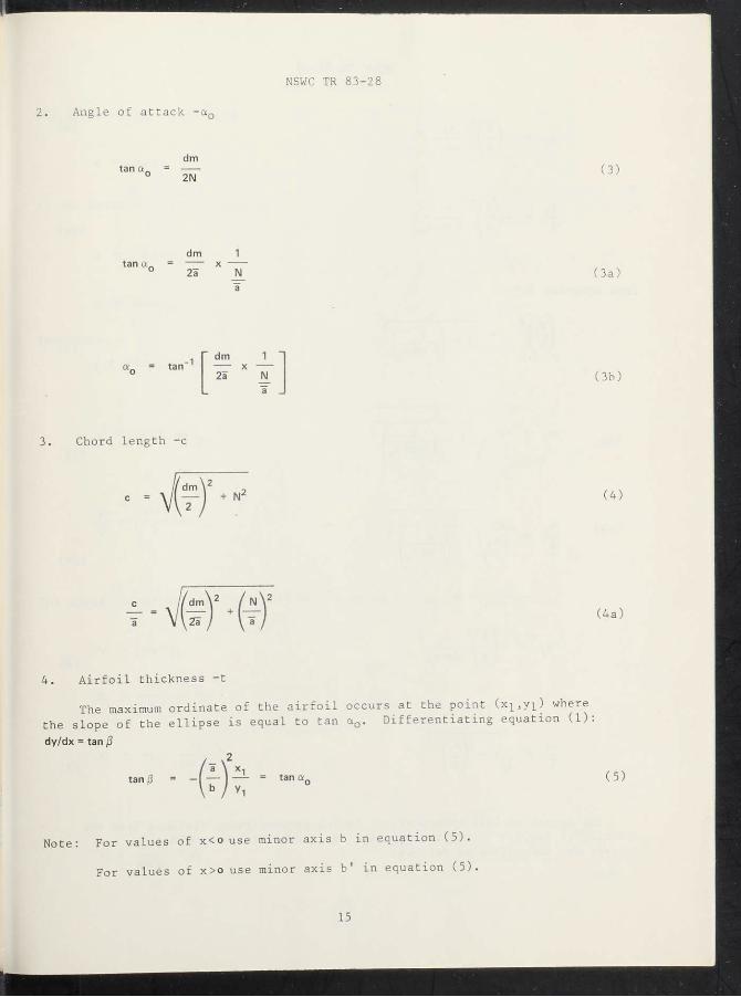
2. Angle of attack -a0
dm
2N (3)
dm 1 tan a „ = x
2a N (3a)
a „ = tan - 1 dm 1
x 2a N (3b)
3. Chord length -c
c = X/l^-j + N2 (4)
(4a)
4. Airfoil thickness -t
The maximum ordinate of the airfoil occurs at the point (xlsyi) where the slope of the ellipse is equal to tan a0. Differentiating equation (1): dy/dx = tan (3
t a n' = ~ l V / y, tan a „ (5)
Note: For values of x<o use minor axis b in equation (5).
For values of x>o use minor axis b' in equation (5).
15

NSWC TR 83-28
tan a„ (3)
Y1 a tan a„
(6a)
from equation (1)
1 + b tan a. (7)
x , = ±b
V 1 + b tan a. (7a)
(7b)
b / tan a (6)
Yi 1 -(5)
(.x2,y2; are determined as follows:
16

NSWC TR 83-28
The locus of the chord line
y = mx + h
at the point x=b; y=o; m=tan a0.
o = —b tan aQ + h
h = b tan aD
Therefore y = x tan a_ + b tan a. ' n o
y = (x + b) tan a o (9)
a \ a y / x + b ltana o (9a)
_ -1 The locus of the airfoil thickness at the point x ^ y ^ m - t a n a
y = mx + h1
—A1 y = - — — + h1 1 tan a.
X1 h. = y , + 1 1 tan a.
V = — + Yi tan a„ (10)
17

NSWC TR 83 - 28
1 / x . - x 1-* (10a)
The coordinates x 2, y 2, are determined by the simultaneous solution of equations (9) and (10).
tan a r
2 1 1 + tan2 a . t a n a „ — b tan a,
(11)
t a n tto = 'A sin 2a
1 + tan2 a „
— = % sin 2a0 { - h + 1 __ t a n a a \ a a tan a „ a (11a)
y2 = (*2 + b' tan a0 (12)
y2 _ / x2 + b a \ a
t a n a „ (12a)
The thickness of the airfoil-like shape is:
1 = 7(xi ~x2»2 + (v, -y2)2
(13)
,xi ~ x2\ 2 , /vi -y2\ 2
(13a)
18
NSWC TR 83 - 28
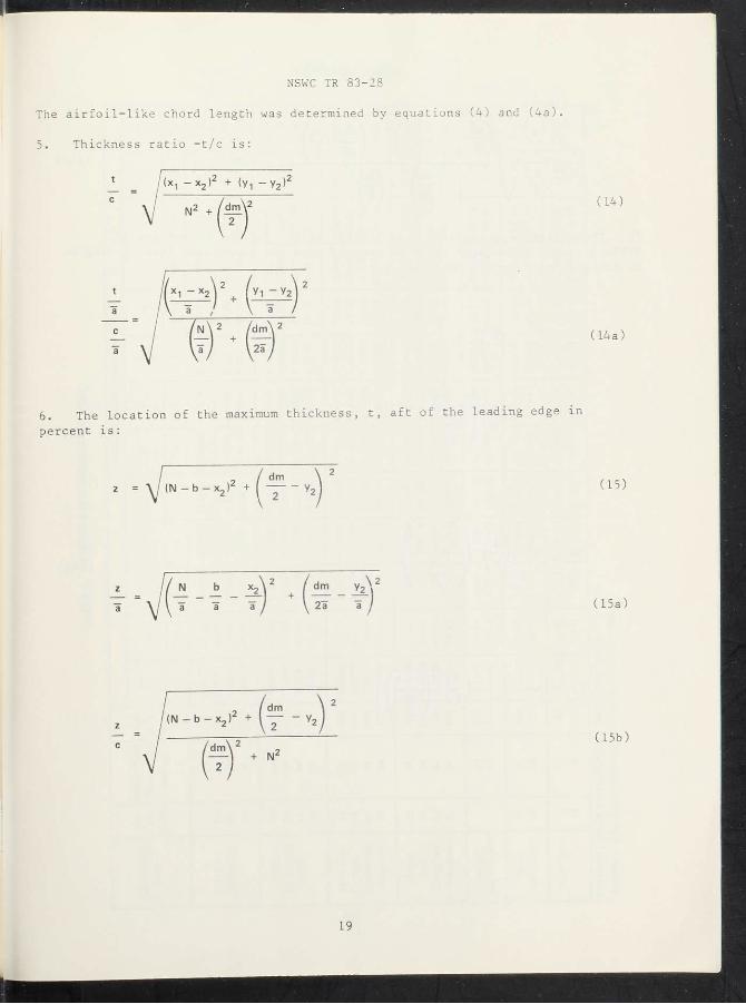
The airfoil-like chord length was determined by equations (4) and (4a).
5. Thickness ratio -t/c is:
6. The location of the maximum thickness, t, aft of the leading edge in percent is:
/ dm z = ^(N-b-Xj)' + - v 2 2 + _ _ „ ( 1 5 )
N b X j \ 2 I dm y2 2
a a a I + \ 2a a I (15a)
/ ( N - b - x , ) 2 + l y - v 2
c / / d m \ 2 , + N (15b)
19

NSWC TR 83 - 28
Z » b x2
2 ~a l\-> "a
d m y2 25
2
d m \ 2 / N
H) *
X100
7. The effective suspension line length, is/Do, for the parachutes Table 3 can be calculated if it is assumed that the suspension line to the gore mainseam at the shirt hem.
20
NSWC TR 83 - 28
21

dm a
2a X 8. S i n 0 o = ~ x ~
Es _ dm
a 2aSin/30
let 2a
where = D / ^ ® ° V — 7 P
o
Kx, values are calculated in Tables 1 and 2
2 sin L
dm
2 a
2 a
D„ 2sin/30 dm
2a
(17a)
(18)
(19)
(19a)
22

NSWC TR 83 - 28
As a sample calculation to demonstrate the method, consider the 24-gore, Flat Circular Parachute.'7 The scale factors from Table 2 for this parachute
N b b Za — = 0.795; — = 0.5758; — = 0.8126; — - = 0.677 a a a D„
Eq. (2), mouth diameter to inflated diameter ratio, dm/2a
dm
2a
dm / /0.795 - 0 . 5 7 5 8 \ 2
2a ~ \l ~ \ 0.8126 0.9629
Eq. (3b), angle of attack, a0
dm 1
2a X N/5
0.9629
0.795 50.4 6°
Eq. (4a), chord length, c/a
2a
^ = J (0.9629)2 + (0.795)2 1.249
7Ludtke, W. P., NOLTR 70-178.
23

NSWC TR 83 - 28
Eq. (7b), coordinate, x^/a.
1 + b tan a:
x 1
T T = ±0.5758 / 1 + / 1 \ 2 . a \ I 0.5758 tan 50.46cj -0.3294
Eq. (8), coordinate, y^/a.
a
Vl = T /0.3294y "a V 10.5758 )
Eq. (11a), coordinate, X2/a.
V, x , b
o - O I - - — - — tan a
' a a tan a a 0
x 2 / 0 3294 \ T = ^ " < 2 X 5 0 . 4 6 = , ^0.8202 — — _ 0 .5758 tan 50.46j = _0.0733
24


NSWC TR 83-28
Eq. (15a), distance of the maximum ordinate from the leading edge, z/a.
i _ a. _ ^ V + x? 2"a a
V^O.795 - 0.5758 + 0.0733)2 + (0.9629 - 0.6088)2 0.4593
Eq. (15c), distance of the maximum ordinate from the leading edge in percent of chord, z/c x 100
0.4593
1.249 x 100 = 36.77%
Eq. (17a), suspension line confluence angle, 60.
"o = „-1
N b x
. 2 I ~ ~ a \ / a a dm 2 a
(30 = tan"1 1 V /0.795 - 0.5758
0.8126/ \ 0.9629 19.02°
-26

NSWC TR 83-28
Eq. (19a), effective suspension line length, S,s/DQ.
Cs 2a 1 dm x x
D q 2 Sin p 0 2a
Cs __ 0.677 x 0.9629
D 0 2 Sin 19.02° 1 - 0 0 0
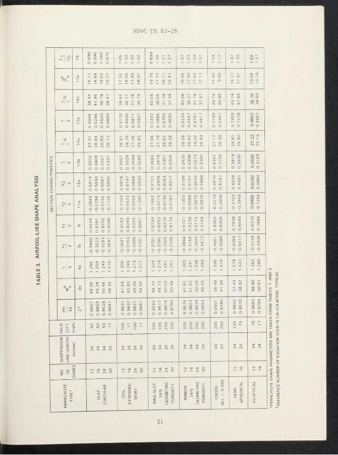
The airfoil-like section characteristics for the 12-^ 16-, 24-, and 30-gore configuration parachutes are listed in Table 3. ' The effects of airfoil thickness and position of the maximum ordinate on aerodynamic lift and drag are discussed in the Aviation Handbook.10 For the convenience of the reader the discussion is reprinted as follows.
"The lift of a relatively thin section tends to increase as the upper camber is increased until a maximum value is reached at a camber of about 18 to 25 percent of the chord. After passing this range, further increase in camber results in a loss of lift.
Values of minimum drag are increased by thickening the section due to increases in upper camber. The value of minimum drag shows no tendency to decrease ultimately as does the lift under similar conditions, but the rate of increase shows a tendency to drop off as higher values of upper camber are reached.
Since the general tendency of both the lift and the drag is to increase as the section is made thicker by alterations in upper camber, it is to be expected that the L/D ratio would attain a m a x i m u m value a t some value or upper camber between that for minimum Drag and maximum Lift.
Tests which have been made to determine the effect of the location of maximum ordinate for the upper surface of an airfoil have indicated that its location should be at about one-third the chord length from the leading eage, its exact position depending upon the thickness of the section. For example, an airfoil having a flat lower surface, and a maximum ordinate of about ID percent of the chord would have this ordinate located about 36 to 38 percent
8 L u d t k e , W. P., NOLTR 69-159.
9 L u d t k e , W. P., NOLTR 70-178.
lOwamer and Johnston, Aviation Handbook, 1st Ed. (New York and Lond McGraw-Hill Book Company, Inc., 1931).
27
NSWC TR 83 - 28
of the chord length back from the leading edge. If the camber is reduced to about 10 percent the maximum ordinate may move forward to about 32 percent of the chord; and a further reduction in thickness to about 7 percent puts the maximum ordinate at about 30 percent of the chord. The indications are that the optimum location for maximum lift is slightly farther forward on the wing than the best location for minimum drag, or for highest value of the L/D rat io,"
The average thickness ratio of the airfoil-like shape of all the parachutes of Table 3 is approximately 26.5 percent (la = 0.87%). This value is very close to the maximum value of 25 percent for a true airfoil with a flat lower surface.11 The location of the maximum ordinate in percent of chord for all parachutes except the Cross and Hemispherical averages to about 38 percent (lo = 1.5%); the Cross parachute approaches a hemispherical inflated shape so the similarity in the location of the maximum ordinate in percent of chord is not a surprise. The Cross parachute maximum ordinate occurs at 47.8 percent of chord (la = 1.2%) as compared to 48.7 percent of chord (la - 1.34%) for the Hemispherical type. What is not consistent with true airfoils is that the true airfoil has a 38 percent maximum ordinate location for a 15 percent thickness ratio while the airfoil-like shape has about 38 percent maximum ordinate location for a thickness ratio of 26.7 percent. Meaning that the airfoil-like shape is an inefficient lift producer compared to a true airfoil. But it is a lift producer, and that is what causes parachute instability.
Many parachutes have a limiting Mach number above which they will not reliably inflate. One method of extending the Mach number range of operation is to modify the canopy inflated shape to a conical configuration. The vent cone angle decreases the thickness ratio two ways. The actual thickness of the airfoil-like section is reduced, and the chord length is increased as shown m Figure 11. The angle of attack, a0, is also somewhat reduced. Decrease in thickness ratio is a technique used by aircraft designers to increase the Critical Mach number of airfoil sections. So the theory is m agreement with actuality. y
COMMENTS ON OTHER AIRFOIL-LIKE SHAPES RELATED TO PARACHUTES
One inflatec gore of a conventional flat solid cloth parachute is illustrated in Figure 12. With some imagination the inflated gore can be transformed rrom the triangular cell to the rectangular cell of Figure 13 Once the rectangular format has been developed, itis not difficult to m gine a number of such cells connectec as in Figure 14 to form the parafoil type device or Figure The transformation technique may be subject to argument but the point is that with imagination new innovations are possible a r g U m e n t '
1 Earner and Johnston, Aviation Handbook.
28

LU
> CL 1 O o z u. < DC o _J < < LU u I 1-2 o o
z o LU a. < X to < LU C/5 Z <
> 0. O z < o o LU I- k-D < I OC O CO < V) DC < a_
LU z u. o O X 1- h-o LLi LU a. U. <
> Li. X a. ill CO O z p! < o LU a: < z o

NSWC TR 83 - 28
F I G U R E 13. S INGLE I N F L A T E D P A R A C H U T E GORE A T CONSTANT TH ICKNESS
30
NSWC TR 83-28

NSWC TR 83-28

NSWC TR 83-2 8
BIBLIOGRAPHY
Irvin Industries, Recovery Systems Design Guide, AFFDL-TR-78-151, Dec 1978.
Ludtke W P. A New Approach to the Determination of the Steady-State Inflated Shape and Included Volume of Several Parachute Types, NOLTR 69-139, 11 Sep 1969.
Ludtke W. P., A New Approach to the Determination of the Steady-State Inflated Shape and Included Volume of Several Parachute Types in 24-Gore and 30-Gore Configurations, NOLTR 70-178, 3 Sep 1970.
Topping, A. D., et al., A Study of Canopy Shapes and Stresses for Parachutes in Steady Descent, WADC TR 55-294, Oct 1955.
Warner and Johnston, Aviation Handbook, 1st Ed. (New York and London: McGraw-Hill Book Company, Inc., 1931).
33

NSWC TR 83 - 28
DEFINITIONS
Airfoil-like shape -
Airfoil thickness -
Chord -
Parachute trim angle
Parafoil parachute -
Permeability -
Reefing -
Static stability -
Steady state canopy shape
The area bounded by the steady state inflated parachute mainseam and a line drawn from the canopy hem to the canopy center line through the vent.
Maximum ordinate of the Airfoil perpendicular to the chord line.
Length of the line drawn from the canopy hem to the canopy center line through the vent.
The angle of attack where the moment due to parachute side force about the parachute suspension line confluence point is equal to, but directionally opposite, to the moment due to the parachute drag force.
A rectangular gliding type of parachute composed of ram air inflated cells of airfoil shape.
Rate of airflow through cloth in CFM/FT2 when measured under a specified pressure differential.
A restriction of a drag producing surface to a diameter less than its diameter when it is fully inflated.
When an aerodynamic shape is held at an angle of attack to the relative wind (as in a wind tunnel) the body is statically stable if the aerodynamic forces acting'upon the body tend to align the body with the relative wind.
Inflated shape of a parachute after parachute deployment.
34

NSWC TR 83-28
NOMENCLATURE
Angle of attack of the airfoil-like section to the relative wind,
degrees.
Angle of attack of the airfoil-like section to the parachute center
line, degrees.
Change in angle of attack due to parachute yaw, degrees.
Static stability pitching moment coefficient.
Airfoil lift coefficient.
Airfoil maximum lift coefficient.
Side force of yawed parachute, lb.
F^ Drag force of yawed parachute, lb.
Moments acting about the suspension line confluence point.
Radius of Disc Gap Band Parachute Crown.
S Width of Disc Gap Band Parachute Gap.
Width of Disc Gap Band Parachute Band.
a o
Aa
C m
CL CT Lmax F s
d M o R
W
X,Y Coordinates in the plane of analysis
C
t
t/C
Z
z/c
Airfoil-like section chord length.
Airfoil-like section thickness.
Airfoil-like section thickness to chord ratio.
Location of the maximum thickness from the leading edge of the
airfoil-like section. Location of the maximum thickness from the leading edge to chord ratio.
35

NSWC TR 83 - 28
NOMENCLATURE (cont.)
Lg Length of suspension lines.
dm Mouth diameter of the inflated canopy, measured at the junction of the
gore mainseam and canopy skirt hem.
2a Maximum inflated diameter of the gore mainseam.
N Canopy depth is the distance from the skirt hem of the canopy to the
vent of the canopy along the parachute center line.
BQ Semi-vertex angle between the suspension lines and the center line of
the parachute, and tangent angle of the mainseam at the canopy hem.
B Tangent slope of the inflated canopy mainseam.
b Minor axis of the ellipse bounded by the major axis a and the vent of
the canopy.
b' Minor axis of the ellipse which includes the skirt hem of the canopy. 2 S Surface area of parachute, ft . o r '
D 0 Nominal diame ter of the canopy, ft = J 4So
Dp Flat constructed diameter of the canopy, ft.
D' Inflated diameter of guide surface type parachute.
L Cross type parachute diameter, ft.
K^ Scale factor o
36
NSWC TR 83-28
DISTRIBUTION
Copies Copies
Commander Naval Air Systems Command Attn: Library Washington, DC 20361
Commander Naval Sea Systems Command Attn: Library Washington, DC 20362
Commanding Officer U. S. Army Mobility
Equipment Research and Development Center
Attn: Technical Document Center
Fort Belvoir, VA 22660
Commanding Officer U. S. Naval Air Development
Center Attn: Library Johnsville, PA 18974
Commanding Officer Naval Ship Research and
Development Center Attn: Library Washington, DC 20007
Commander U. S. Army Aviation Systems
Command Attn: Library St. Louis, MO 63166
Commander U. S. Army Munitions Command Attn: Technical Library Dover, NJ 07801
Commander U. S. Army Weapons Command Attn: Technical Library Research and Development
Directorate Rock Island, IL 61201
Office of Naval Research Attn: Library Washington, DC 20360
Defense Technical Information Center
Cameron Station Alexandria, VA 22314
U. S. Naval Academy Attn: Library Annapolis, MD 21402
Dept. of Aerospace Eng. & Mech. University of Minnesota Attn: William Garrard Minneapolis, MN 55455
Internal Distribution: U10 (Kalaf) U13 (Diehlman) U13 (McNelia) U13 (Fiske) U13 (Ludtke) U13 (Murphy) U13 (Douglas) U13 (Velez) U13 (Tarulli) E431 E432 E35 (GIDEP) TJ
1 1 1 1
15 1 1 1 1 9 3 1 1
(1)

