a viable base isolation strategy for the advanced … viable base isolation strategy for the...
TRANSCRIPT
Contemporary Engineering Sciences, Vol. 7, 2014, no. 17, 817 - 834 HIKARI Ltd, www.m-hikari.com
http://dx.doi.org/10.12988/ces.2014.4549
A Viable Base Isolation Strategy for the Advanced
Seismic Retrofit of an R/C Building
Stefano Sorace 1 and Gloria Terenzi 2
1Department of Civil Engineering and Architecture Via delle Scienze 206, 33100 Udine, Italy
2Department of Civil and Environmental Engineering
Via di S. Marta 3, 50139 Florence, Italy Copyright © 2014 Stefano Sorace and Gloria Terenzi. This is an open access article distributed under the Creative Commons Attribution License, which permits unrestricted use, distribution, and reproduction in any medium, provided the original work is properly cited.
Abstract
A base isolation seismic retrofit solution for a reinforced concrete school building, designed with earlier Technical Standards, is presented in this paper. The structural characteristics of the building are initially discussed. The mechanical parameters and installation details of the isolation system, incorporating double friction pendulum sliding bearings as protective devices, are then illustrated. The results of the performance assessment analyses carried out in original and rehabilitated conditions show a remarkable enhancement of the seismic response capacities of the structure in base-isolated configuration. The high performance levels postulated in the retrofit design are reached with notably lower costs and architectural intrusion as compared to traditional rehabilitation strategies. Keywords: Seismic retrofit, R/C structures, Base isolation 1 Introduction The reinforced concrete (R/C) frame structures designed in Italy during the 1970s and early 1980s under the first two editions of the reference Seismic Standards, characterized by a traditional strength-based design conception, show performance capacities below the basic levels required by the latest Standards editions, especially in terms of member ductility and displacement-related damage control. Especially in the case of public and strategic buildings, this imposes to
818 Stefano Sorace and Gloria Terenzi develop careful structural assessment analyses according to the current normative performance evaluation criteria, as well as to plan their possible seismic retrofit, consistently with the available economic resources [1]–[4]. To this aim, in the past decade attention has been paid to motion control-based rehabilitation technologies [5], [6], which include the two wide classes of passive supplemental energy dissipation systems and seismic isolation systems. A R/C school building in Italy, well representative of the characteristics of the early-Standards-designed stock of edifices mentioned above, is examined in this paper. The building, situated in the town of Bisignano — province of Cosenza, Calabria, was assumed as a benchmark structure for a Research Project financed by the Italian Department of Civil Protection, which this study belongs to, with the aim of developing comprehensive seismic assessment analyses, as well as of proposing motion control-based rehabilitation hypotheses likely to be applied in the next future. Along this research line, a base isolation system including double friction pendulum (DFP) sliding bearings at the column feet, is proposed in this paper for the case study building.
Friction pendulum bearings, either with single [7], double [8] or triple [9], [10] sliding surfaces, are currently the most widely applied isolation system worldwide. Indeed, thousands of bearings are in service in several earthquake-prone countries, including Italy, where about 5000 single and about 2500 double friction pendulum devices have been installed in new apartment blocks built in L’Aquila after the severe earthquake that struck the city in 2009, and several other designs based on the application of friction pendulum isolators were developed during the subsequent years, for new buildings as well as for the retrofit of existing ones.
In particular, the following contents are presented in the next sections: a synthesis of the structural and modal characteristics of the case study building; the mechanical parameters, dimensions, layouts and locations selected for the DFP elements constituting the base isolation system; the seismic performance assessment analyses in original and retrofitted conditions carried out according to a full non-linear dynamic approach; details of the installation of the isolators; and estimates of the costs of the intervention. 2 Case study building
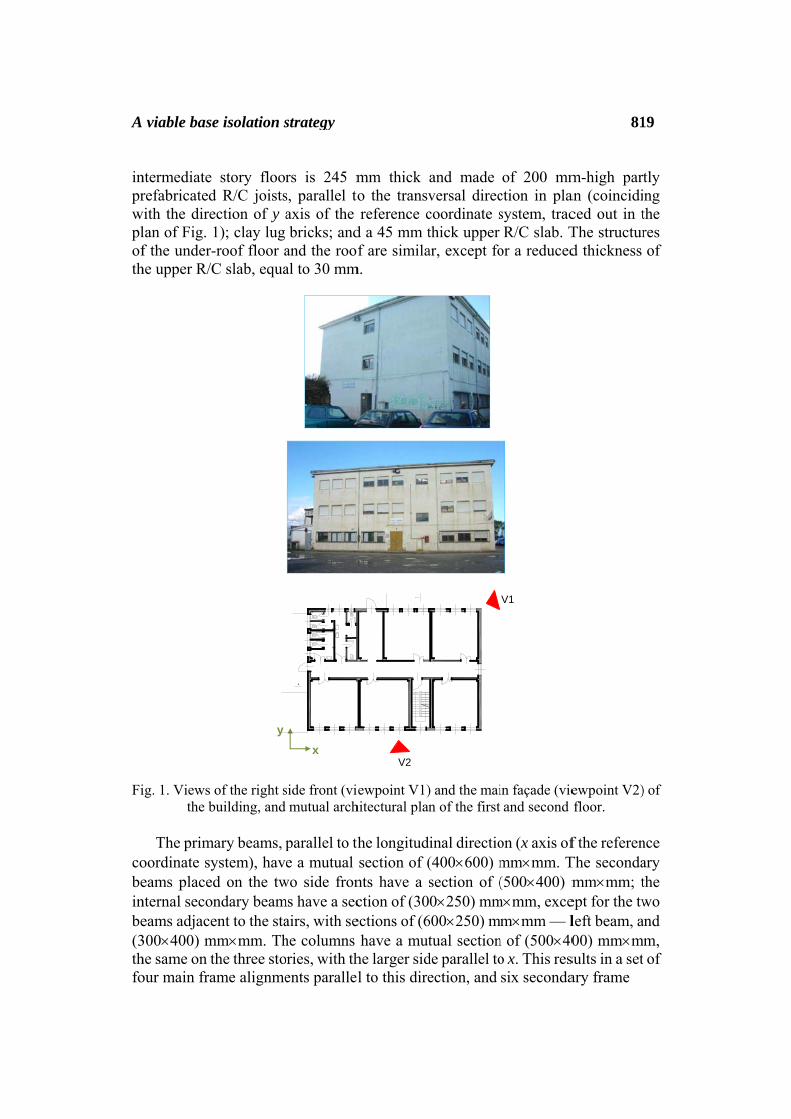
2.1 General characteristics Fig. 1 shows two photographic views and the mutual architectural plan of the first and second floor of the building, which consists of a three-story R/C frame structure, substantially regular both in plan and elevation. The structure was designed according to the 1980 edition of Italian Seismic Standards and completed in 1983. The interstory heights range from about 3.2 m to about 3.4 m, for a total height of about 9.9 m at the under-roof level. The roof is supported by a set of small brick walls erected over the floor slab. The structure of the two
A inprwplofth Fi
cobeinbe(3thfo
viable base
ntermediate refabricated
with the direlan of Fig. 1f the under-he upper R/C
ig. 1. Views the b
The primaoordinate syeams placednternal seconeams adjace300×400) mhe same on tour main fra
y
e isolation s
story floord R/C joistsection of y a1); clay lug -roof floor aC slab, equa
of the right sbuilding, and
ary beams, pystem), havd on the twndary beament to the sta
mm×mm. Ththe three stoame alignme
x
A
strategy
rs is 245 ms, parallel toaxis of the bricks; and
and the roofal to 30 mm
side front (vimutual arch
parallel to the a mutual
wo side fronms have a secairs, with sehe columns ories, with thents parallel
V2
B
mm thick o the transvreference c
d a 45 mm tf are simila
m.
ewpoint V1)hitectural plan
he longitudsection of (
nts have a sction of (30ections of (6
have a muthe larger sidl to this dire
and made versal direccoordinate sthick upper ar, except fo
) and the main of the first
inal directio(400×600) msection of (0×250) mm
600×250) mtual section
de parallel toection, and
V1
of 200 mmction in plasystem, tracR/C slab. T
or a reduced
in façade (vieand second
on (x axis ofmm×mm. T(500×400) m
m×mm, excem×mm — l
n of (500×40o x. This ressix seconda
81
m-high partan (coincidiced out in tThe structurd thickness
ewpoint V2)floor.
f the referenThe secondamm×mm; t
ept for the twleft beam, a00) mm×m
sults in a setary frame
19
tly ng the res of
) of
nce ary the wo and m, of
820 Stefano Sorace and Gloria Terenzi alignments parallel to the y axis. The foundations are constituted by a mesh of inverse T-shaped R/C beams, with a mutual 1000 mm-high and 1000 mm-wide section, a 300 mm-high flange and a 700 mm-high and 500 mm-wide web. The ground floor is not constituted by a R/C structure, but is made of an about 60 mm unreinforced concrete slab cast over a loose stone layer, which fills the volume determined by the mesh of foundation beams up to the column feet.
2.2 Investigation campaigns
As a benchmark structure for the Research Project recalled in the Introduction,
the building was made the object of a careful investigation campaign on materials and structural members [11], including on-site Son-Reb and pacometric analyses, and laboratory tests on concrete and steel bar samples. All the original design drawings were also examined. Ultrasonic and sclerometric tests were carried out on several beams and columns, and relevant data were mutually crossed and calibrated by comparison with the ones of the laboratory tests on the concrete samples. Based on these elaborations, the mean cubic compressive strength of concrete of the frame members resulted to be equal to 24.6 MPa. The tensile strength tests on the steel bars highlighted a minimum yield stress and a limit stress equal to 315 and 378 MPa, respectively. These data were integrated with a non-destructive survey campaign carried out by pacometric tests to check the positions and diameters of the bars derived from the design drawings. The geometrical data on reinforcements were confirmed by the tests.
2.3 Modal parameters
The modal analysis carried out by the finite element model of the structure,
generated by the SAP2000NL software [12], showed that the first vibration mode is purely translational along the weakest direction y, with a period of 0.98 s and an effective modal mass (EMM) equal to 78.9% of the total seismic mass. The third mode is purely translational along x, with period of 0.52 s and EMM equal to 82.9%. The fourth and sixth modes are again purely translational along y and x, with periods of 0.26 s and 0.16 s, and EMMs of 15% and 12.6%, respectively. By summing up these EMM values and the ones of the first and third modes, total EMMs of 93.9%, and 95.5% are obtained for the two first translational modes in y and x. The second and fifth modes are purely rotational around the vertical axis z, with EMMs equal to 30.5% and 23.6%. These data highlight that the structure is not appreciably affected by the torsional components of response, reflecting its substantial regularity in plan (with the only exception of stairs, placed in a slightly eccentric position) and elevation.
2.4 Seismic performance evaluation analysis
The performance evaluation enquiry was carried out for the four reference
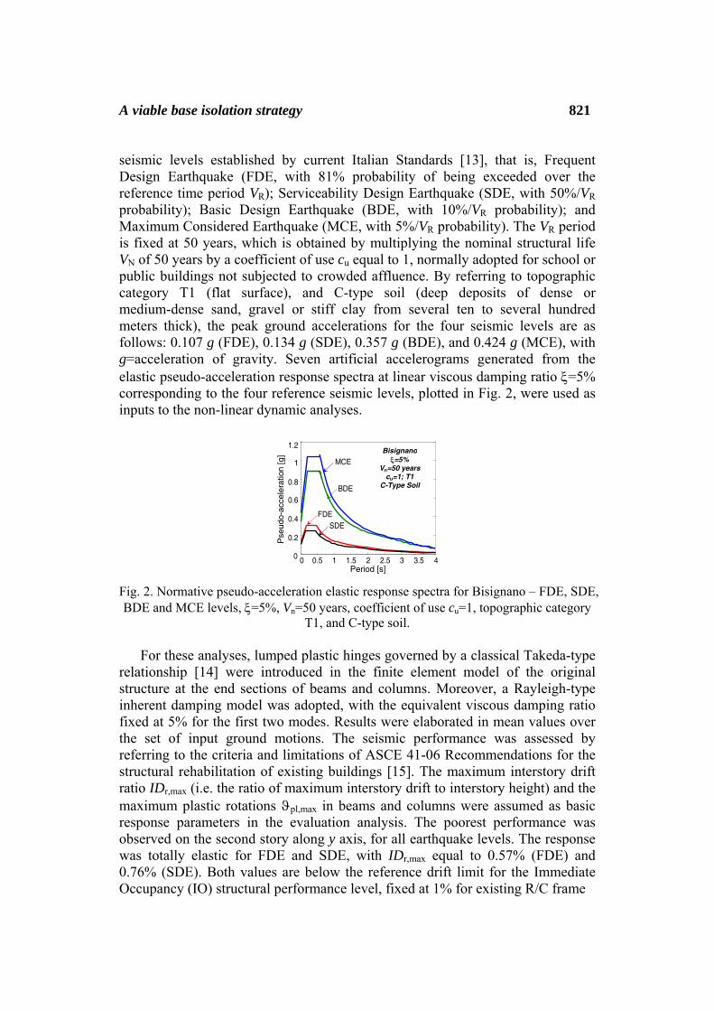
A viable base isolation strategy 821 seismic levels established by current Italian Standards [13], that is, Frequent Design Earthquake (FDE, with 81% probability of being exceeded over the reference time period VR); Serviceability Design Earthquake (SDE, with 50%/VR probability); Basic Design Earthquake (BDE, with 10%/VR probability); and Maximum Considered Earthquake (MCE, with 5%/VR probability). The VR period is fixed at 50 years, which is obtained by multiplying the nominal structural life VN of 50 years by a coefficient of use cu equal to 1, normally adopted for school or public buildings not subjected to crowded affluence. By referring to topographic category T1 (flat surface), and C-type soil (deep deposits of dense or medium-dense sand, gravel or stiff clay from several ten to several hundred meters thick), the peak ground accelerations for the four seismic levels are as follows: 0.107 g (FDE), 0.134 g (SDE), 0.357 g (BDE), and 0.424 g (MCE), with g=acceleration of gravity. Seven artificial accelerograms generated from the elastic pseudo-acceleration response spectra at linear viscous damping ratio ξ=5% corresponding to the four reference seismic levels, plotted in Fig. 2, were used as inputs to the non-linear dynamic analyses. Fig. 2. Normative pseudo-acceleration elastic response spectra for Bisignano – FDE, SDE, BDE and MCE levels, ξ=5%, Vn=50 years, coefficient of use cu=1, topographic category
T1, and C-type soil.
For these analyses, lumped plastic hinges governed by a classical Takeda-type relationship [14] were introduced in the finite element model of the original structure at the end sections of beams and columns. Moreover, a Rayleigh-type inherent damping model was adopted, with the equivalent viscous damping ratio fixed at 5% for the first two modes. Results were elaborated in mean values over the set of input ground motions. The seismic performance was assessed by referring to the criteria and limitations of ASCE 41-06 Recommendations for the structural rehabilitation of existing buildings [15]. The maximum interstory drift ratio IDr,max (i.e. the ratio of maximum interstory drift to interstory height) and the maximum plastic rotations ϑpl,max in beams and columns were assumed as basic response parameters in the evaluation analysis. The poorest performance was observed on the second story along y axis, for all earthquake levels. The response was totally elastic for FDE and SDE, with IDr,max equal to 0.57% (FDE) and 0.76% (SDE). Both values are below the reference drift limit for the Immediate Occupancy (IO) structural performance level, fixed at 1% for existing R/C frame
0 0.5 1 1.5 2 2.5 3 3.5 40
0.2
0.4
0.6
0.8
1
1.2
MCE
BDE
FDE SDE
Bisignano ξ=5%
Vn=50 years cu=1; T1
C-Type Soil
Pse
udo-
acce
lera
tion
[g]
Period [s]
822 Stefano Sorace and Gloria Terenzi buildings by ASCE/SEI 41-06, as well as by other international Standards and Recommendations. Concerning BDE, activation of about 45% of plastic hinges in the entire model, and maximum interstory drift ratios of 2.8% on the second story along y, were found. The maximum plastic rotation angles amounted to 0.014 radians in the beams parallel to y, and to 0.011 radians in columns. This means that performance does not meet the drift limitation of 2%, relevant to the Life Safety (LS) level (although the plastic rotation limits of 0.015 radians for beams and 0.013 radians for columns, calculated for the geometric and reinforcement characteristics of these members, are met), and as a consequence it falls within the Limited Safety (LimS) structural performance range. The number of activated plastic hinges increases to 70% for the input action scaled at the MCE amplitude, with ϑpl,max equal to 0.018 radians in beams parallel to y and 0.015 radians in columns, and IDr,max equal to 3.5%. These values are just below the minimum requirements for the Collapse Prevention (CP) level (mutual rotation limit of 0.02 radians for beams and columns, and allowable drift threshold of 4%). A slightly better performance emerges for the x direction (the second story being the most stressed along this axis too), where the FDE–IO, SDE–IO, and MCE–CP earthquake levels–structural performance levels correlations already found for y are assessed again, whereas a better correlation (LS instead of LimS) comes out for the BDE.
3 Base isolation retrofit hypothesis
3.1 Characteristics of DFP devices incorporated in the base isolation system
Double friction pendulum isolators have been proposed and implemented [8]
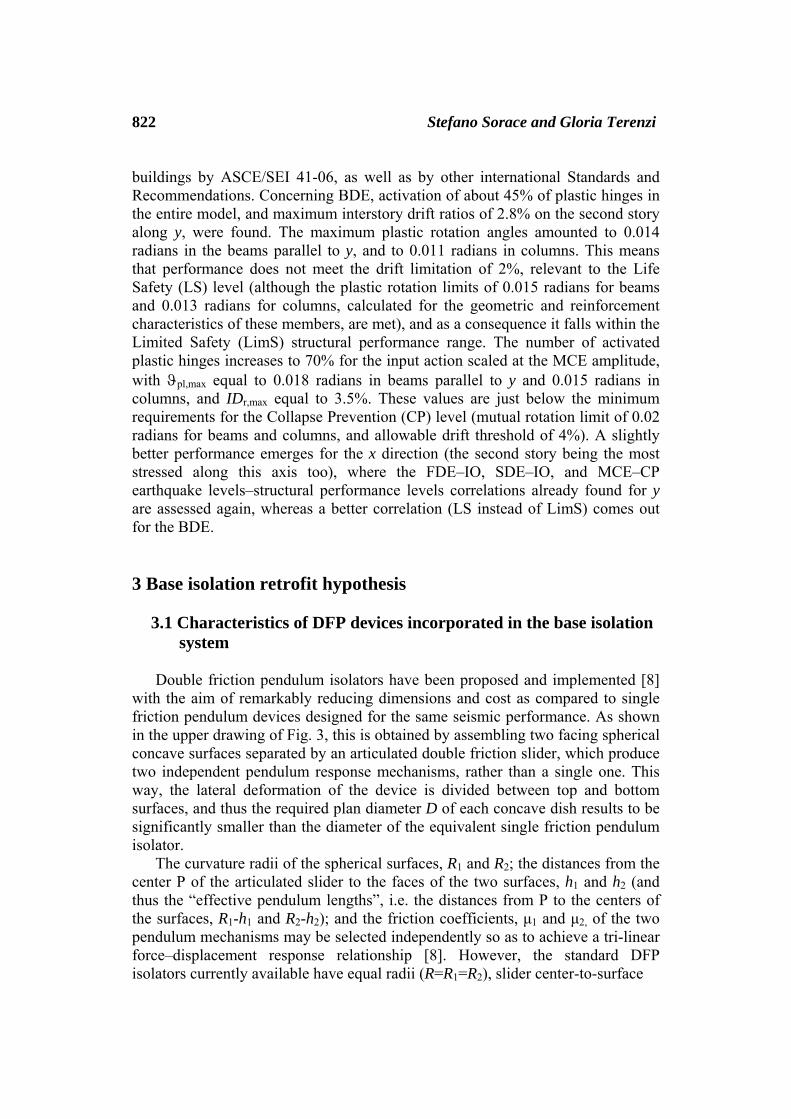
with the aim of remarkably reducing dimensions and cost as compared to single friction pendulum devices designed for the same seismic performance. As shown in the upper drawing of Fig. 3, this is obtained by assembling two facing spherical concave surfaces separated by an articulated double friction slider, which produce two independent pendulum response mechanisms, rather than a single one. This way, the lateral deformation of the device is divided between top and bottom surfaces, and thus the required plan diameter D of each concave dish results to be significantly smaller than the diameter of the equivalent single friction pendulum isolator.
The curvature radii of the spherical surfaces, R1 and R2; the distances from the center P of the articulated slider to the faces of the two surfaces, h1 and h2 (and thus the “effective pendulum lengths”, i.e. the distances from P to the centers of the surfaces, R1-h1 and R2-h2); and the friction coefficients, μ1 and μ2, of the two pendulum mechanisms may be selected independently so as to achieve a tri-linear force–displacement response relationship [8]. However, the standard DFP isolators currently available have equal radii (R=R1=R2), slider center-to-surface
A viable base isolation strategy 823 distances (h=h1=h2, which means equal effective pendulum lengths, R-h=R1-h1=R2-h2), and friction coefficients (μ=μ1=μ2) for the two surfaces, as indicated in the drawing of Fig. 3. This causes DFP devices in standard production — which can be defined “symmetrical” DFP isolators for the
properties above — to behave exactly like a single friction pendulum bearing, with μ friction coefficient and resulting effective pendulum length LDFP equal to twice the effective length of each surface, i.e. LDFP=2·(R-h)=2R-2h.
Fig. 3. Cross section of a symmetrical DFP isolator, characterized by equal concave surfaces and friction coefficients, and corresponding schematic Ft-d response cycle.
The total reaction force of a DFP bearing, Ft, is given by the sum of the
pendulum response component, Fp, relevant to the isolation function, and the friction component, Ff, governing the dissipative function. For symmetrical DFP isolators, Fp, Ff and Ft have the following expressions:
)()()(DFP
p tdL
tVtF = (1)
)(μ)(f tVtF = (2)
)(μ)()()(
DFPt tVtd
LtVtF += (3)
with d(t)=displacement, and V(t)=vertical load acting at the pivot point. It is noted that although V is a function of time too, it slightly varies during seismic response, due to the strong reduction of earthquake loads on the superstructure determined by the filtering action of the base isolation system.
Said Ft,max the maximum value of Ft, reached when the maximum displacement of the device, dmax, is attained:
H
D
Upper Spherical Surface
Lower Spherical Surface P h
h
Ft
d
kd
kd
ke
︶︵
f0−F
︶︵
maxt,−F
︶︵
maxt,+F
︶︵
f0+F
824 Stefano Sorace and Gloria Terenzi
VdLVF μmaxDFP
maxt, += (4)
where V is the corresponding vertical load, the “linear equivalent” — or secant — stiffness of the isolator, ke, normally assumed as the conventional stiffness parameter in manufacturer’s catalogues, is defined as follows: V
dLdF
k ⎟⎟⎠
⎞⎜⎜⎝
⎛+==
maxDFPmax
maxt,e
μ1 (5)
In order to quickly evaluate ke, in relation (5) V is fixed as the maximum
value of the vertical load admitted in seismic response conditions, provided in the manufacturer’s catalogues too. Based on the ke expression above, the equivalent vibration period of the isolator, Te, is
⎟⎟⎠
⎞⎜⎜⎝
⎛+
=
maxDFP
e μ11π2
dLg
T (6)
The equivalent viscous damping ratio, ξe, is expressed as:
1μ
1π2ξ
DFP
maxe
+⋅=
Ld
(7)
The values of Fp, Ff, Ft, Ft,max and dmax must be intended both with positive
and negative sign, as indicated in the schematized Ft–d cycle of a symmetrical DFP device traced out in the lower image of Fig. 3, where the mechanical parameters included in expressions (1) through (7) are highlighted. In the same graph, kd represents the “dynamic” — or tangent — stiffness of the device, i.e. the value attained when the positive, )(
t0+F , or negative, )(
t0−F , friction force at rest is
exceeded, and the response follows one of the two sloped branches of the parallelogram-like shaped cycle.
For the analyses carried out in this study, the finite element model of the DFP isolators was generated by the special “Friction Isolator” link element available in the library of SAP2000NL code, originally implemented in [16] and subsequently included in this software to reproduce the behaviour of any type of friction slider devices. This is a biaxial friction-pendulum element with coupled friction properties for the deformations along the two reference local axes in plan, post-slip stiffness in both directions, and “gap”-type behaviour in vertical direction. Friction and pendulum components act in parallel, with the former ruled by Wen hysteretic law [17] and the latter by the linear model formulated in [7].
A viable base isolation strategy 825 3.2 Base isolation system layout and installation
The base isolation retrofit hypothesis consists in incorporating a DFP device at
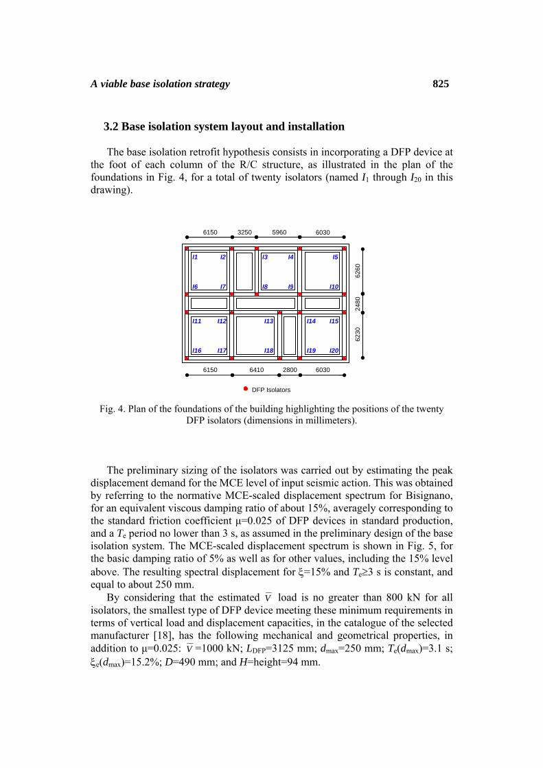
the foot of each column of the R/C structure, as illustrated in the plan of the foundations in Fig. 4, for a total of twenty isolators (named I1 through I20 in this drawing).
Fig. 4. Plan of the foundations of the building highlighting the positions of the twenty DFP isolators (dimensions in millimeters).
The preliminary sizing of the isolators was carried out by estimating the peak displacement demand for the MCE level of input seismic action. This was obtained by referring to the normative MCE-scaled displacement spectrum for Bisignano, for an equivalent viscous damping ratio of about 15%, averagely corresponding to the standard friction coefficient μ=0.025 of DFP devices in standard production, and a Te period no lower than 3 s, as assumed in the preliminary design of the base isolation system. The MCE-scaled displacement spectrum is shown in Fig. 5, for the basic damping ratio of 5% as well as for other values, including the 15% level above. The resulting spectral displacement for ξ=15% and Te≥3 s is constant, and equal to about 250 mm.
By considering that the estimated V load is no greater than 800 kN for all isolators, the smallest type of DFP device meeting these minimum requirements in terms of vertical load and displacement capacities, in the catalogue of the selected manufacturer [18], has the following mechanical and geometrical properties, in addition to μ=0.025: V =1000 kN; LDFP=3125 mm; dmax=250 mm; Te(dmax)=3.1 s; ξe(dmax)=15.2%; D=490 mm; and H=height=94 mm.
6150 3250 5960 6030
6230
24
80
6260
6150 6410 2800 6030
DFP Isolators
I1 I2 I3 I4 I5
I6 I7 I8 I9 I10
I12 I13 I14 I15
I16 I17 I18 I19 I20
I11

826 Stefano Sorace and Gloria Terenzi
Fig. 5. Normative displacement elastic response spectrum for Bisignano – MCE level, ξ=5%, 10%, 15% and 20%, Vn=50 years, coefficient of use cu=1, topographic category T1,
and C-type soil.
The technical installation of the isolation system consists, for each column, of the following steps: 1) demolishing the unreinforced concrete slab and the loose stone layer, as well as the infills and partitions in contact (if any) with the column, on the ground floor; 2) positioning a steel “collar” around the column to contrast the electro-hydraulic actuators to be placed over the extrados of the foundation beams beneath the base section of the column; 3) pressurizing the actuators, and transferring to them the axial force of the column; 4) cutting the bottom end area of the column with the help of a diamond saw, up to 450 mm from the column base; 5) filling four holes at the extrados of the foundation beams, where the connectors of the isolator must be introduced and anchored; 6) positioning the isolator, to which an upper steel plate is bolted, so as to constitute the horizontal formwork for the on-site cast described in step 11; 7) inserting the connectors of the isolator in the holes and filling the latter with high-strength cement mortar; 8) grouting with the same mortar a gap about 15 mm wide below the lower plate of the isolator, in order to adjust its final position and reach a precise horizontal layout; 9) positioning the reinforcing bars of the R/C “capital” to be built in the residual space comprised between the steel plate bolted at the extrados of the isolator and the new bottom section of the column resulting from the removal of its end portion (step 4); 10) positioning the fixing steel axes — to be grouted in the R/C capital too — where the bolts of the flanges of the beams supporting the new steel ground floor must be subsequently introduced and screwed (step 12); 11) casting the capital; 12) positioning the beams mentioned in point 10, made of HEB 240 (primary beams, parallel to x) and a pair of HEA 160 (secondary beams, parallel to y) Italian profiles, and introducing and screwing the bolts of the beam flanges to the steel axes embedded in the capital.
Once this twelve-step installation process is completed for all columns, the remaining steps of the structural works consist in: installing the remaining secondary beams of the ground floor, made of single HEA 160 profiles and situated along the span of the primary beams at a mutual distance of 1000 mm; positioning the HI-bond corrugated steel sheets of the floor over the upper flange of the secondary beams, as well as the sheets of welded wire mesh constituting the reinforcement of the upper R/C slab; and finally, casting the slab. A drawing illustrating the final configuration of an isolator at the end of the structural works
Bisignano
C-Type Soil
V =50 years
0 0.5 1 1.5 2 2.5 3 3.5 40
50
100
150200
250 300
350
400
450
500
Dis
plac
emen
t [m
m]
Period [s]
ξ=5%
ξ=10% ξ=15%
ξ=20%
Bisignano Vn=50 years
cu=1; T1 C-Type Soil
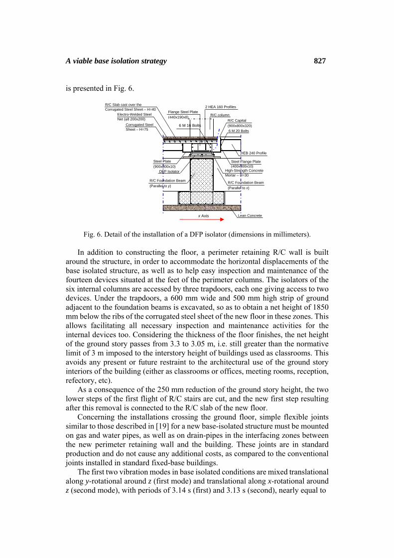
A viable base isolation strategy 827 is presented in Fig. 6.
Fig. 6. Detail of the installation of a DFP isolator (dimensions in millimeters). In addition to constructing the floor, a perimeter retaining R/C wall is built
around the structure, in order to accommodate the horizontal displacements of the base isolated structure, as well as to help easy inspection and maintenance of the fourteen devices situated at the feet of the perimeter columns. The isolators of the six internal columns are accessed by three trapdoors, each one giving access to two devices. Under the trapdoors, a 600 mm wide and 500 mm high strip of ground adjacent to the foundation beams is excavated, so as to obtain a net height of 1850 mm below the ribs of the corrugated steel sheet of the new floor in these zones. This allows facilitating all necessary inspection and maintenance activities for the internal devices too. Considering the thickness of the floor finishes, the net height of the ground story passes from 3.3 to 3.05 m, i.e. still greater than the normative limit of 3 m imposed to the interstory height of buildings used as classrooms. This avoids any present or future restraint to the architectural use of the ground story interiors of the building (either as classrooms or offices, meeting rooms, reception, refectory, etc).
As a consequence of the 250 mm reduction of the ground story height, the two lower steps of the first flight of R/C stairs are cut, and the new first step resulting after this removal is connected to the R/C slab of the new floor.
Concerning the installations crossing the ground floor, simple flexible joints similar to those described in [19] for a new base-isolated structure must be mounted on gas and water pipes, as well as on drain-pipes in the interfacing zones between the new perimeter retaining wall and the building. These joints are in standard production and do not cause any additional costs, as compared to the conventional joints installed in standard fixed-base buildings.
The first two vibration modes in base isolated conditions are mixed translational along y-rotational around z (first mode) and translational along x-rotational around z (second mode), with periods of 3.14 s (first) and 3.13 s (second), nearly equal to
Lean Concrete
R/C column Flange Steel Plate (440x190x8)
R/C Capital (900x800x320)
Steel Plate (900x800x10)
Corrugated Steel Sheet – H=75 6 M 20 Bolts
HEB 240 Profile
Steel Flange Plate (400x300x10)
High-Strength Concrete Mortar – H=30
R/C Foundation Beam (Parallel to x)
R/C Foundation Beam (Parallel to y)
Electro-Welded Steel Net (φ8 200x200)
x Axis
6 M 16 Bolts
R/C Slab cast over the Corrugated Steel Sheet – H=40 2 HEA 160 Profiles
DFP Isolator

828 Stefano Sorace and Gloria Terenzi the Te value computed from (6) for the μ, LDFP and dmax values of the selected isolators, as a consequence of the negligible contribution of the superstructure deformability to these modes. This is also confirmed in terms of effective modal masses (EMM), nearly equal to 100% of the total seismic mass along x (99.8% — first mode), and along y (99.4% — second mode). The EMMs relevant to the rotational component around z are equal to 51.4% (first mode) and 20% (second mode). The third mode is purely rotational, with period of 2.68 s and EMM equal to 28.3%. By summing up the latter value and the 51.4% and 20% mass contributions above, 99.7% EMM is obtained for the rotational component with the first three modes only.
3.3 Seismic performance evaluation in retrofitted conditions
The performance evaluation enquiry carried out in original conditions was duplicated in the base isolation retrofit hypothesis. The performance objectives postulated in the rehabilitation design consist in reaching: a Damage Control (DC) structural level for MCE, with at most some slight plastic rotations (i.e. limited below 0.003 radians) in few beams, and 1.5% maximum interstory drift ratios; an Immediate Occupancy (IO) structural level for BDE, with 1% IDr,max values, in order to obtain an elastic structural response, with limited and reparable non-structural damage; an IO non-structural (IO/N) level for SDE, assessed by 0.5% maximum drift ratios (satisfied by the original structure in x direction, but not in y, as mentioned above), to prevent any appreciable damage of partitions and infills; and an Operational (OP) structural and non-structural level for FDE, identified by a 0.33% IDr,max limit, so as to obtain a totally undamaged response of partitions and infills, as well as of any other non-structural member.
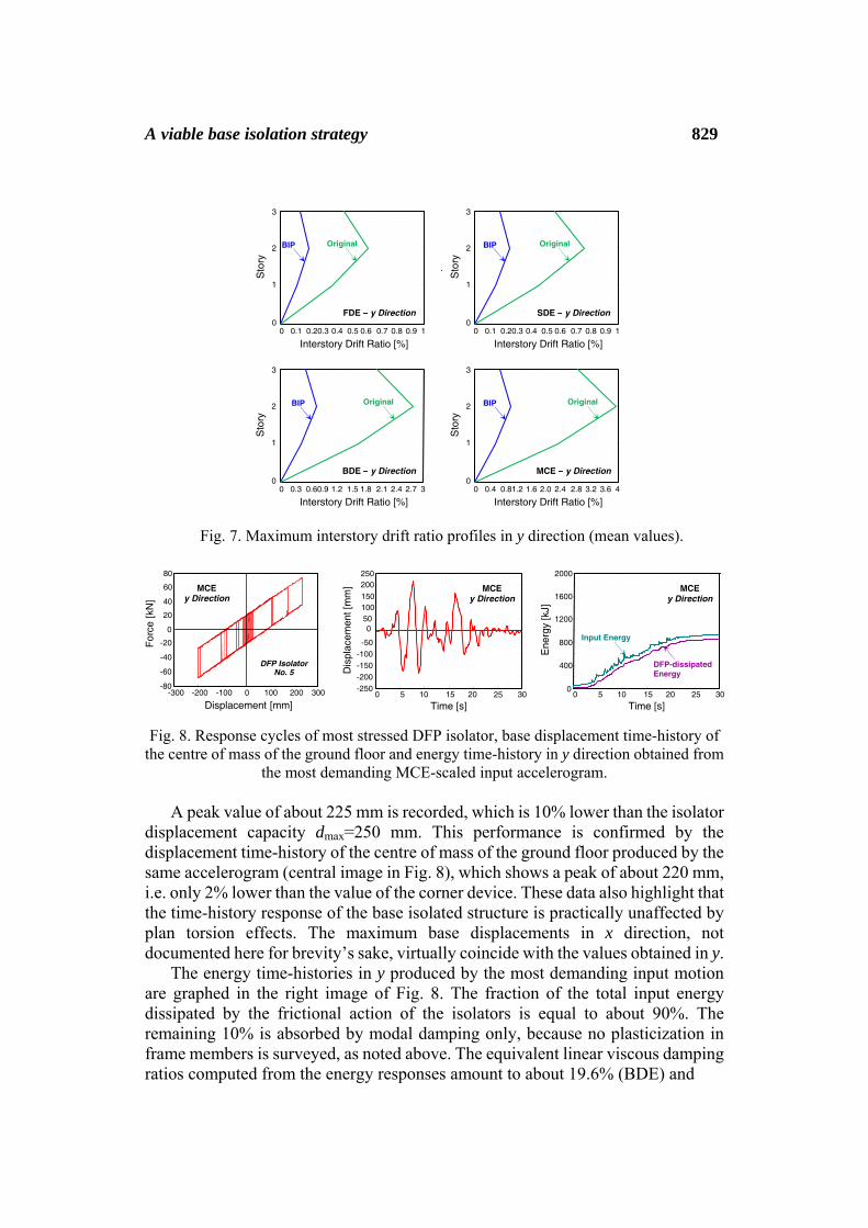
The mean peak drift profiles derived from the four earthquake input levels are plotted in Fig. 7 for the weakest direction y in original and protected (named BIP in these graphs) configuration. IDr,max values are equal to 0.2%, 0.25%, 0.76% and 1.03%, for FDE, SDE, BDE and MCE, respectively. The first two values are both below the target OP threshold of 0.33%, whereas the drift ratio relevant to BDE is below the IO structural limitation of 1%. This is slightly exceeded by the MCE response, for which the DC performance level is attained, also considering that no plasticization is observed in all frame members. As a consequence, no strengthening of the latter, as well as of foundation beams, is needed for this advanced retrofit solution.
The peak displacements of the DFP isolators were checked at the MCE input level. The response cycles obtained from the most demanding MCE-scaled input accelerogram for one of the four corner bearings (namely No. I5 in Fig. 4), which are subjected to the maximum displacements due to their position in plan, is plotted in the left image of Fig. 8.
A viable base isolation strategy 829
Fig. 7. Maximum interstory drift ratio profiles in y direction (mean values). Fig. 8. Response cycles of most stressed DFP isolator, base displacement time-history of
the centre of mass of the ground floor and energy time-history in y direction obtained from the most demanding MCE-scaled input accelerogram.
A peak value of about 225 mm is recorded, which is 10% lower than the isolator
displacement capacity dmax=250 mm. This performance is confirmed by the displacement time-history of the centre of mass of the ground floor produced by the same accelerogram (central image in Fig. 8), which shows a peak of about 220 mm, i.e. only 2% lower than the value of the corner device. These data also highlight that the time-history response of the base isolated structure is practically unaffected by plan torsion effects. The maximum base displacements in x direction, not documented here for brevity’s sake, virtually coincide with the values obtained in y.
The energy time-histories in y produced by the most demanding input motion are graphed in the right image of Fig. 8. The fraction of the total input energy dissipated by the frictional action of the isolators is equal to about 90%. The remaining 10% is absorbed by modal damping only, because no plasticization in frame members is surveyed, as noted above. The equivalent linear viscous damping ratios computed from the energy responses amount to about 19.6% (BDE) and
Displacement [mm] -300 -200 0 100 200 300
-80 -60 -40
-20
0
20
40 60 80
F
orce
[kN
]
MCE y Direction
DFP Isolator No. 5
-100 0 5 10 15 20 25 300
400
800
1200
1600
2000
Time [s]
Ene
rgy
[kJ]
MCE y Direction
Input Energy
DFP-dissipated Energy
0 5 10 15 20 25 30
-150
-50
100
250
Time [s]
Dis
plac
emen
t [m
m] MCE
y Direction 150
200
-100
-200-250
50 0
0 0.1 0.2 0.3 0.4 0.5 0.6 0.7 0.8 0.9 1 0
1
2
3
SDE – y Direction
Sto
ry
Original
Interstory Drift Ratio [%]
BIP
0 0.3 0.6 0.9 1.2 1.5 1.8 2.1 2.4 2.7 3 0
1
2
3
BDE – y Direction
Sto
ry
Original
Interstory Drift Ratio [%]
BIP
0 0.1 0.2 0.3 0.4 0.5 0.6 0.7 0.8 0.9 1 0
1
2
3
FDE – y Direction
Sto
ry
Original
Interstory Drift Ratio [%]
BIP
0 0.4 0.8 1.2 1.6 2.4 2.8 3.2 3.6 4 0
1
2
3
MCE – y Direction
Sto
ry
Original
Interstory Drift Ratio [%]
BIP
2.0

830 Stefano Sorace and Gloria Terenzi 17.4% (MCE), for both directions in plan. These values are well correlated with the ξe predictions of expression (7) obtained by substituting therein the peak base displacements deducted from the time-history analyses to dmax. The total base shear of the structure is reduced by 75% (BDE) and 66% (MCE) in y direction, and by 72% (BDE) and 65% (MCE) in x, when passing from original to rehabilitated conditions.
A supplementary control on the response of the isolation system was carried out by developing a further set of time-history analyses, where several near-fault real ground motions recorded during the greatest earthquakes in Italy over the latest thirty years were taken as inputs, in order to produce highly demanding response conditions for the base isolated building. The fault-normal N-S main shock component recorded in L’Aquila on April 6, 2009 (03:32 a.m.) at the Parking seismographic station downtown, whose pseudo-acceleration and displacement response spectra at 5% viscous damping ratio are plotted in Fig. 9, proved to be the most demanding ground motion. This component, named AQK in the record database of L’Aquila earthquake, is characterized by a distance of 5.6 km from the surface projection of the causative fault, moment magnitude Mw=6.3, and peak ground acceleration of 0.353 g. Although the latter is practically equal to the value of the BDE-scaled normative seismic action, due to the near-fault characteristics of the AQK motion record, the spectral displacements are rather high (>200 mm) in the vibration period range of interest for the base isolated structure (3-3.5 s).
Fig. 9. Pseudo-acceleration and displacement elastic response spectra at ξ=5% of NS AQK
component – L’Aquila earthquake of 6 April 2009.
The results are summarized in Fig. 10, where the response graphs presented in Fig. 8 above for the most demanding normative accelerogram and the y direction, are plotted for the AQK input motion too. The peak displacements of the corner isolator I5 and the center of mass are equal to about 186 and 182 mm, respectively, i.e. 17% lower than the corresponding values found for the MCE-scaled artificial accelerogram. Slightly lower differences come out in terms of dissipated energy (10%), energy absorbed by the DFP devices (9%) and base shear (14%), guaranteeing a satisfactory performance of the isolation system also for the real near-fault motion. At the same time, the quality of the response is visibly different in the two cases, because the normative accelerograms produce a considerably greater number of comparable acceleration peaks, as expected, in place of the single
0 0.5 1 1.5 2 2.5 3 3.5 40 0.3 0.6 0.9 1.2 1.5 1.8 2.1 2.4 2.7 3
Pse
udo-
acce
lera
tion
[g]
Period [s]
L’Aquila EQ 6 April 2009
NS AQK component
ξ=5%
0 0.5 1 1.5 2 2.5 3 3.5 4 0
50
100
150200
250 300
350
400
450
500
Dis
plac
emen
t [m
m]
Period [s]
L’Aquila EQ 6 April 2009
NS AQK component
ξ=5%
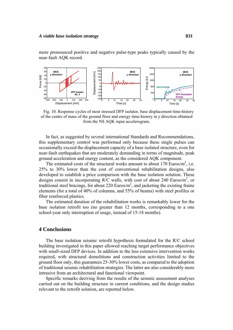
A viable base isolation strategy 831 more pronounced positive and negative pulse-type peaks typically caused by the near-fault AQK record.
Fig. 10. Response cycles of most stressed DFP isolator, base displacement time-history of the centre of mass of the ground floor and energy time-history in y direction obtained
from the NS AQK input accelerogram.
In fact, as suggested by several international Standards and Recommendations,
this supplementary control was performed only because these single pulses can occasionally exceed the displacement capacity of a base isolated structure, even for near-fault earthquakes that are moderately demanding in terms of magnitude, peak ground acceleration and energy content, as the considered AQK component.
The estimated costs of the structural works amount to about 170 Euros/m2, i.e. 25% to 30% lower than the cost of conventional rehabilitation designs, also developed to establish a price comparison with the base isolation solution. These designs consist in incorporating R/C walls, with cost of about 240 Euros/m2, or traditional steel bracings, for about 220 Euros/m2, and jacketing the existing frame elements (for a total of 40% of columns, and 55% of beams) with steel profiles or fiber reinforced plastics.
The estimated duration of the rehabilitation works is remarkably lower for the base isolation retrofit too (no greater than 12 months, corresponding to a one school-year only interruption of usage, instead of 15-18 months). 4 Conclusions
The base isolation seismic retrofit hypothesis formulated for the R/C school building investigated in this paper allowed reaching target performance objectives with small-sized DFP devices. In addition to the less extensive intervention works required, with structural demolitions and construction activities limited to the ground floor only, this guarantees 25-30% lower costs, as compared to the adoption of traditional seismic rehabilitation strategies. The latter are also considerably more intrusive from an architectural and functional viewpoint.
Specific remarks deriving from the results of the seismic assessment analyses carried out on the building structure in current conditions, and the design studies relevant to the retrofit solution, are reported below.
Displacement [mm] -300 -200 0 100 200 300
-80 -60 -40
-20
0
20
40 60 80
F
orce
[kN
]
MCE y Direction
DFP Isolator No. 5
-100 0 5 10 15 20 25 30
-150
-50
50 100
250
Time [s]
Dis
plac
emen
t [m
m] MCE
y Direction 150
0
200
-100
-200 -250
0 5 10 15 20 25 300
400
800
1200
1600
2000
Time [s]
Ene
rgy
[kJ]
MCE y Direction
Input Energy
DFP-dissipated Energy

832 Stefano Sorace and Gloria Terenzi
– Starting from a poor seismic performance of the original structure, as assessed
by FDE–IO, SDE–IO and MCE–CP correlations between earthquake and performance levels for both axes in plan, and BDE–LimS and BDE–LS for y and x, respectively, the incorporation of the base isolation system helps meeting the strict performance requirements postulated for the rehabilitation design. These requirements are synthesized by FDE–OP, SDE–OP, BDE–IO and MCE–DC correlations, for both axes, in retrofitted configuration.
– As a consequence, no strengthening of beams and columns, nor of foundations, is needed for the latter. On the other hand, extensive strengthening interventions would be required in conventional rehabilitation designs, causing longer interruptions of usage, which represents another fundamental criterion when choosing the best seismic rehabilitation strategies for school and public buildings.
– In addition to the drastic cut in interstory drifts, as well as in rotations and stresses of frame members, which allows reaching the enhanced multi-level seismic performance objectives recalled above, the filtering action of base isolation also causes the total base shear of the structure to fall by over 70% at the BDE, and 60% at the MCE, when passing from original to rehabilitated conditions.
– The frictional response of the DFP sliding bearings restrains base displacements within limits consistent with the adoption of simple flexible joints for gas, water and drain ducts crossing the ground floor. The base displacement demand was successfully checked also by the supplementary time-history inquiry developed with the real near-fault AQK component of 2009 L’Aquila earthquake as input.
Based on these findings, Bisignano school case study confirms the potential of the considered base isolation technology as retrofit strategy for the stock of R/C buildings having similar characteristics, either pre-normative or designed with earlier Seismic Standards editions.
Acknowledgements. The study reported in this paper was financed by the Italian Department of Civil Protection within the ReLUIS-DPC Project 2014/2016. The authors gratefully acknowledge this financial support. References [1] I. Iervolino, G. Manfredi, M. Polese, G.M. Verderame and G. Fabbrocino,
Seismic risk of R.C. building classes, Engineering Structures, 29 (2007), 813 – 820.
[2] F. Jalayer, L. Elefante, I. Iervolino and G. Manfredi, Knowledge-based
performance assessment of existing RC buildings, Journal of Earthquake Engineering, 15 (2011), 362 – 389.

A viable base isolation strategy 833
[3] G.E. Thermou and S.J. Pantazopoulou, Assessment indices for the seismic
vulnerability of existing R.C. buildings, Earthquake Engineering and Structural Dynamics, 40 (2011), 293 – 313.
[4] S. Sorace and G. Terenzi, Structural assessment of a modern heritage
building, Engineering Structures, 49 (2013), 743 – 755. [5] M.C. Constantinou, T.T. Soong and G.F. Dargush, Passive energy
dissipation systems for structural design and retrofit, Monograph series No. 1, MCEER, Buffalo, NY, 1998.
[6] C. Christopoulos and A. Filiatrault, Principles of passive supplemental
damping and seismic isolation, IUSS Press, Pavia, Italy, 2006. [7] V. Zayas, S. Low and S. Mahin, A simple pendulum technique for achieving
seismic isolation, Earthquake Spectra, 6 (1990), 317 – 334.
[8] D.M. Fenz and M.C. Constantinou, Behaviour of the double concave friction pendulum bearing, Earthquake Engineering and Structural Dynamics, 35 (2006), 1403 – 1424.
[9] D.M. Fenz and M.C. Constantinou, Spherical sliding isolation bearings with
adaptive behavior: Theory, Earthquake Engineering and Structural Dynamics, 37 (2008), 163 – 183.
[10] T.A. Morgan, and S.A. Mahin, Achieving reliable seismic performance
enhancement using multi-stage friction pendulum isolators, Earthquake Engineering and Structural Dynamics, 39 (2010), 1443 – 1461.
[11] Italian Department of Civil Protection, Technical Report no. 031/10A.03 [in
Italian], Rome, Italy, 2004.
[12] CSI, SAP2000NL. Structural analysis programs – Theoretical and users manual, Release no. 16.03, Berkeley, CA, 2014.
[13] Italian Council of Public Works, Technical Standards on Constructions [in
Italian], Rome, Italy, 2008.
[14] T. Takeda, M.A. Sozen and N.N. Nielsen, Reinforced concrete response to simulated earthquakes, ASCE Journal of the Structural Division, 96 (1970), 2557 – 2573.
834 Stefano Sorace and Gloria Terenzi
[15] American Society of Civil Engineers, Seismic rehabilitation of existing
buildings – ASCE/SEI 41-06, Reston, VA, 2006.
[16] S. Nagarajaiah, A.M. Reinhorn and M.C. Constantinou, 3D-Basis: Nonlinear dynamic analysis of three-dimensional base isolated structures, Technical Report NCEER No. 91-0005, Buffalo, NY, 1991.
[17] Y.K. Wen, Method for random vibration of hysteretic system, ASCE Journal
of the Engineering Mechanics Division, 102 (1976), 249 – 263.
[18] FIP, Anti-seismic devices product division, http://www.fip-group.it, 2013.
[19] S. Sorace and G. Terenzi, Analysis and demonstrative application of a base isolation/supplemental damping technology, Earthquake Spectra, 24 (2008), 775 – 793.
Received: May 11, 2014