a uml profile for modeling workflow and business processes
TRANSCRIPT
1
Activity Nets:
A UML profile for modeling workflow and business processes
Author: Gregor v. Bochmann, SITE, University of Ottawa
(August 27, 2000)
1. Introduction
1.1. Purpose of this document
Workflow modeling is important in a large range of application domains, includingbusiness process architectures, factory automation, and various work processes, such assoftware engineering processes. Workflow modeling is characterized by a high level ofabstraction and the concentration on such concepts as work activities, resources requiredto perform these activities, and the objects that are created and transformed by theseprocesses. In order to obtain useful models one needs a suitable notation for describingworkflow models, and automated tools for verifying the consistency of these models andanalyzing their performance. This document describes such a notation, which is similar toUML Activity Diagrams [1].
This document defines a UML profile, called Activity Nets, which is closely related toActivity Diagrams. The profile includes modeling concepts that have proven suitable formodeling business process architectures and other activies of concurrent processes. Thebasic concepts are activities, and participants that participate in the activities, such asactors, resources and created or consumed objects. These concepts are part of the OPALmodeling language [5]. They are very similar to the UML concepts ActionState andObjectFlowState, respectively, which are used in the context of UML Activity Diagrams.These concepts are also related to the new semantics of actions described in [2]. The heredefined profile provides a precise dynamic semantics for these modeling concepts whichcan be used as a basis for the construction of automated analysis tools which provideperformance simulations for the established models (for an example of such a tool, see[5]).
It is noted that the semantics of Activity Nets is very similar to the one of UML ActivityGraphs, but defined independently of State Machines. Therefore this semantic definitioncould be used, after small adaptations, as an alternative to the semantic definition ofActivity Diagrams based on state-machine oriented concepts as presently defined in UML[1].
2
1.2. Overview
In this section we provide a cursory high-level overview of the basic concepts of theprofile and the motivation behind them. See references [5, 6, 7] for more comprehensivedescriptions.
1.2.1. Semantics
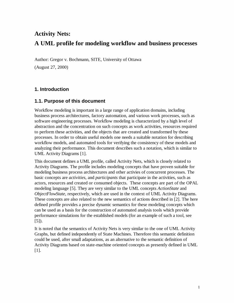
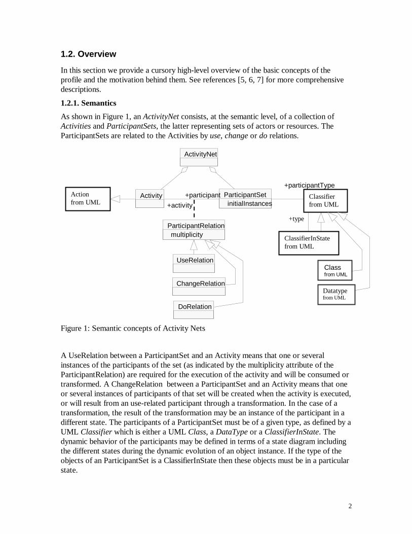
As shown in Figure 1, an ActivityNet consists, at the semantic level, of a collection ofActivities and ParticipantSets, the latter representing sets of actors or resources. TheParticipantSets are related to the Activities by use, change or do relations.
+type
UseRelation
ChangeRelation
DoRelation
ActivityNet
ParticipantRelation multiplicity
Activity ParticipantSet initialInstances
+participant
+activity
+participantType Action from UML
Classifier from UML
ClassifierInState from UML
Class from UML
Datatype from UML
Figure 1: Semantic concepts of Activity Nets
A UseRelation between a ParticipantSet and an Activity means that one or severalinstances of the participants of the set (as indicated by the multiplicity attribute of theParticipantRelation) are required for the execution of the activity and will be consumed ortransformed. A ChangeRelation between a ParticipantSet and an Activity means that oneor several instances of participants of that set will be created when the activity is executed,or will result from an use-related participant through a transformation. In the case of atransformation, the result of the transformation may be an instance of the participant in adifferent state. The participants of a ParticipantSet must be of a given type, as defined by aUML Classifier which is either a UML Class, a DataType or a ClassifierInState. Thedynamic behavior of the participants may be defined in terms of a state diagram includingthe different states during the dynamic evolution of an object instance. If the type of theobjects of an ParticipantSet is a ClassifierInState then these objects must be in a particularstate.
3
A DoRelation between a ParticipantSet and an Activity means that one or severalinstances of the participants of the set are required during the execution of the activity,however, these participants are not consumed nor modified. Examples of such participantsare actors that perform the activity, or non-consumable resources, e.g. CPU processingpower or information from a database.
At the basic semantic level, an ActivityNet defines the order in which the differentactivities may be executed. The precondition for the execution of an activity is thepresence of a sufficient number of participant instances in the ParticipantSets related bythe use and do relations. When the activity starts its execution, these instances areremoved from their ParticipantSets, and when the activity completes, the instances fromdo-related ParticipantSets are reconstituted and new instances are inserted in the change-related ParticipantSets. The initial number of instances in the ParticipantSets is indicatedby the initialInstances attribute. We note that the basic semantics of Activity Nets is thesame as Petri nets [10], a well-known formalism for modeling systems with concurrency.This is an advantage because techniques and tools developed for the analysis of Petri netscan be adapted for the analysis of Activity Nets.
A second level of semantics, called Stochastic Activity Nets, can be provided forperformance simulations and is related to the semantics of stochastic Petri nets [11]. Atthis level, each activity is characterized by its execution time, which may either be aconstant or a probability distribution, such as for instance a uniform distribution between aminimum and a maximum value. Models at this level allows for performance evaluationusing analytical or simulation tools.
Another, complementary refinement of the semantics, in the following called AttributedActivity Nets, allows the consideration of attributes of participants and additionalpreconditions for activities depending on the attribute values of the object instancesparticipating in the activity. At this level, it becomes important to consider the order inwhich the participants of a given ParticipantSet are created and consumed, because theyare identified by their characteristic attribute values. Normally it is assumed that eachParticipantSet enforces a FIFO ordering.
1.2.2. Notation
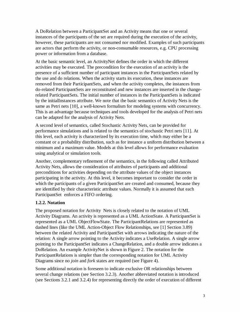
The proposed notation for Activity Nets is closely related to the notation of UMLActivity Diagrams. An activity is represented as a UML ActionState. A ParticipantSet isrepresented as a UML ObjectFlowState. The ParticipantRelations are represented asdashed lines (like the UML Action-Object Flow Relationships, see [1] Section 3.89)between the related Activity and ParticipantSet with arrows indicating the nature of therelation: A single arrow pointing to the Activity indicates a UseRelation. A single arrowpointing to the ParticipantSet indicates a ChangeRelation, and a double arrow indicates aDoRelation. An example ActivityNet is shown in Figure 2. The notation for theParticipantRelations is simpler than the corresponding notation for UML ActivityDiagrams since no join and fork states are required (see Figure 4).
Some additional notation is foreseen to indicate exclusive OR relationships betweenseveral change relations (see Section 3.2.3). Another abbreviated notation is introduced(see Sections 3.2.1 and 3.2.4) for representing directly the order of execution of different
4
activities (without the intermediate ParticipantSets). It is also proposed (see Section 3.2.2)that DoRelations may be represented in an alternate form, for instance using the Swimlanenotation of the UML Activity Diagrams (see [1] Section 3.88) or the “component”notation proposed by Use Case Maps [9]. Notations for substructure of Activities arediscussed in Section 3.2.5.
{xor} Prepare LR
Client [waiting]
Clerk
LR [completed]
Manager
Review LR
Database
LR [refused]
LR [accepted]
mail out refusal
sign contract
Figure 2: Example of an Activity Net: Processing of a loan request (LR)
1.2.3. Relationship with other UML views
Activity nets are typically of a more abstract nature than certain other dynamic views, suchas UML Sequence and Collaboration diagrams. ActivityNet diagrams are thereforesuitable for making early abstract models which closely relate to UML Use Cases. Incontrast to use cases, however, they may include part of the internal structure of a systemor organization which provides the services described by the use cases. Sequence andcollaboration diagrams, together with more detailed UML Static Structure diagrams maybe used during the later phases of the system development process for a moreimplementation-oriented description of the system.
Typically, an activity net is complemented with diagrams showing the classificationhierarchy of the participants involved in the activities. Sometimes this information may becomplemented with associations between the different classes of participants; theseassociations may represent containment relationships or transformation relationshipsrelated to the activities of the described processes. If the state transitions of theparticipants are important to be documented, UML StateChart diagrams may be used forthis purpose. This is further discussed in Section 3.3.
1.2.4. Relation to other UML developments
As mentioned above, Activity Nets are conceptually quite close to Activity Diagrams,although their semantics is defined in a different manner. The concepts of Activity Netsare also relevant in the context of other ongoing UML developments, such as thefollowing.
(a) Action Semantics
Work is ongoing to define the semantics of actions [2]. In this context, data flow relationsare defined which are similar to the ParticipantRelations (Use and Change) of Activity
5
Nets. One could define data flow diagrams as a specialization of Activity Nets, asexplained in more detail in Section 2.6.
(b) Revised semantics for Activity Diagrams
In the context of the development of UML Version 2, work is ongoing to revise thesemantic definition of Activity Diagrams. Given the similarity of the modeling concepts,the semantics of Activity Nets may be used for this purpose.
(c) Event-Based Architectures in Enterprise Application Integration (EAI)
A new OMG request for proposal (RfP) on EAI has a due date of November 30, 2000. Itappears that the concepts of Activity Nets are quite relevant in this context. For instance,an EAI Business Model , as defined in the RfP, could be modeled as an Activity Net. AnEAI Business Event may be modeled by the arrival of an object in a ParticipantSet. In factthe loose coupling to be realized in EAI by messaging can be realized by the objects inParticipantSets and their Use and Change relations with Activities. Concerning the Data-Based Architecture of EAI, it could be realized by the use of Do relationships which relatean Activity with a data resource (represented by the related ParticipantSet) which is usedor updated by the Activity.
(d) Software Process Engineering (SPE)
The software engineering process may be considered as a special case of workflow. AOMG working group is in the process of considering the proposals that have beensubmitted in response to the OMG SPE Management Request for Proposals (RfP). Forthe software engineering process many specific types of activities, deliverables, resourcesand techniques must be defined, however, they may be considered specializations of theActivities and Participants of Activity Nets. If we consider in particular the InitialSubmission from Fijitsu/DMR [13], we may note the following. The Process Component(see for instance Figure 3-3 of the Fijitsu/DMR submission) can be identified with anActivity (of Activity Nets). A Process Component may be refined and described bysubprocesses, like an Activity may be defined with a substructure (as described in Section3.2.5 below). In such a way, a Phase may consist of several subprocesses, each resultingin a particular Milestone, which can be modeled as a Participant created by the subprocessActivity (as indicated by a ChangeRelation). The Resource Types defined in Figure 3-4 ofthe submission may be considered to be specializations the UML Classifier (or Class)which defines the types of Participants in the Activity Net model of Figure 1. ADeliverable Types could normally be modeled by a ParticipantSet which has aChangeRelation with the process that created the deliverable, and a UseRelation with theprocess that uses that deliverable. Information Units and Teams may be represented byParticipantSets which have a DoRelation with the processes that use the information unitor with the team that performs the process. Therefore it seems that the concepts ofActivity Nets correspond to the Metaclass definitions given in Section 3.2 of thesubmission. A corresponding relationship with UML Activity Diagrams is alreadyindicated in Figures 3-3 and 3-4 of the submission.
(e) Workflow Management Facility
6
A document submitted to OMG by the Workflow Management Coalition [12] describesworkflow interfaces which should provide the possibility for interworking betweendifferent workflows, possibly modeled with different tools. The core workflow interfacesenumerated in Section 2.1.1 of [12] have some similarity with the concepts of ActivityNets. In particular, a WfActivity may be identified with an Activity. Also a WfProcess andWfRequester may be modeled by an Activity. A WfProcess could typically be modeled byan activity which is refined into a number of subactivities, as described in Section 3.2.5below. A WfResource could be modeled as a ParticipantSet which is related by aDoRelation with the activity that requires the resource.
(f) Enterprise Distributed Object Model (EDOC)
To some extend, Activity Nets may also be useful as concepts for the modeling ofEnterprise Distributed Object Models as defined in the OMG Request for Proposals onEDOC. In fact, the Initial Submission from SUN contains the notion of execution order ofdifferent activities, as described in Section 3.2.1 of this document.
2. Semantics
2.1. Semantic overview and relation with standard UML
This profile is based on the UML standard and does not require any other prerequisiteprofiles.
This profile is additive; in other words, it can be used in conjunction with any other meta-classes from standard UML. However, for the purpose of modeling the dynamic aspects ofbusiness workflow architectures, it is suggested to only use a subset of the standardizedUML notations, as discussed in Section 3.3.
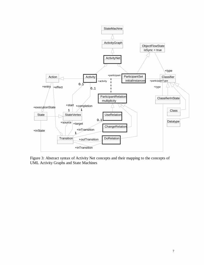
The abstract syntax of the concepts introduced in this profile is given in Figure 1. Theabstract syntax of the mapping of these concepts to the UML concepts of Activity Graphsis shown in Figure 3.
The basic semantics of Activity Nets is described first in a stand-alone fashion,independently of UML, in Section 2.2. The same semantics can be obtained through themapping of Activity Nets to UML concepts as shown in Figure 3 and explained in Section2.3. We note that this mapping is based on UML Activity Graphs. However, an alternatemapping could be based on the action semantics defined in [2], as discussed in Section 2.4.In fact, a notation related to data flow diagrams is defined in [2], and it should be notedthat data flow diagrams may be considered a constrained version of Activity Nets.
Unless otherwise stated, the here defined semantics is the basic semantics of Activity Nets.The specializations required for Stochastic Activity Nets and Attributed Activity Nets areexplicitly mentioned.
7
StateMachine
ActivityGraph
ClassifierInState
State
+inState
Action
+entry
StateVertex UseRelation
ChangeRelation
Transition
+effect
+target+source
1
0..1
+inTransition1
0..1
+outTransition DoRelation
+inTransition
ActivityNet
ParticipantRelationmultiplicity
ObjectFlowStateisSync = true
+executionState
Activity
1
0..1
1
+start
0..1
1
0..1
1+completion
0..1
ParticipantSetinitialInstances
+participant
+activity
Classifier
+type
+participantType
+type
Class
Datatype
Figure 3: Abstract syntax of Activity Net concepts and their mapping to the concepts ofUML Activity Graphs and State Machines

8
2.2. Stand-alone definition of Activity Nets
2.2.1. Basic semantic structure of Activity Nets
The static syntax of the concepts of Activity Nets are shown in Figure 1 and explained inthe following.
Activity
From the semantic point of view, an Activity is a specialization of an Action as defined inUML (in other words, the base class of the Activity stereotype is the class Action). Ingeneral, an activity takes as input some participants from related ParticipantSets(UseRelation), produces as output some participants from other related ParticipantSets(ChangeRelation), and requires during its execution some participants from other relatedParticipantSets (DoRelation). As such, an activity represents an action which changes thestate of the system represented by the Activity Net, which is defined in terms of theinstances of participant instances available at the different ParticipantSets of the ActivityNet.
Associations
participant: through the designated ParticipantRelation, indicates the type of participantsthat are involved in the Activity and their relation with the activity. TheParticipantRelation must be of one of the following subtypes: UseRelation,ChangeRelation, or DoRelation.
(containment relation): Each activity is part of an ActivityNet.
ParticipantSet
A ParticipantSet represents a set (bag) of object instances which all belong to a specifiedclass, which is defined by the UML Classifier pointed to by the participantType. ThisClassifier may be a ClassifierInState (as defined in UML Activity Diagrams), whichindicates that the object instances are within a specified state (which must be defined intheir associated StateMachine).
In the case of the basic semantics of Activity Nets, there is no need for the identity of thedifferent object instances represented by a ParticipantSet; it is sufficient to count theirnumber (since without attributes, they are all identical).
Associations
activity: through the ParticipantRelation, indicates the activities in which participantsfrom this ParticipantSet are involved. The ParticipantRelation must be of one of thefollowing subtypes: UseRelation, ChangeRelation, or DoRelation.
(containment relation): Each activity is part of an ActivityNet.
participantType: designates the Classifier which describes the type of participantscontained in the ParticipantSet.
9
Attributes
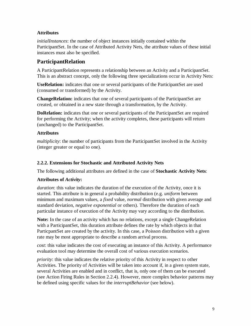
initialInstances: the number of object instances initially contained within theParticipantSet. In the case of Attributed Activity Nets, the attribute values of these initialinstances must also be specified.
ParticipantRelation
A ParticipantRelation represents a relationship between an Activity and a ParticipantSet.This is an abstract concept, only the following three specializations occur in Activity Nets:
UseRelation: indicates that one or several participants of the ParticipantSet are used(consumed or transformed) by the Activity.
ChangeRelation: indicates that one of several participants of the ParticipantSet arecreated, or obtained in a new state through a transformation, by the Activity.
DoRelation: indicates that one or several participants of the ParticipantSet are requiredfor performing the Activity; when the activity completes, these participants will return(unchanged) to the ParticipantSet.
Attributes
multiplicity: the number of participants from the ParticipantSet involved in the Activity(integer greater or equal to one).
2.2.2. Extensions for Stochastic and Attributed Activity Nets
The following additional attributes are defined in the case of Stochastic Activity Nets:
Attributes of Activity:
duration: this value indicates the duration of the execution of the Activity, once it isstarted. This attribute is in general a probability distribution (e.g. uniform betweenminimum and maximum values, a fixed value, normal distribution with given average andstandard deviation, negative exponential or others). Therefore the duration of eachparticular instance of execution of the Activity may vary according to the distribution.
Note: In the case of an activity which has no relations, except a single ChangeRelationwith a ParticipantSet, this duration attribute defines the rate by which objects in thatParticpantSet are created by the activity. In this case, a Poisson distribution with a givenrate may be most appropriate to describe a random arrival process.
cost: this value indicates the cost of executing an instance of this Activity. A performanceevaluation tool may determine the overall cost of various execution scenarios.
priority: this value indicates the relative priority of this Activity in respect to otherActivities. The priority of Activities will be taken into account if, in a given system state,several Activities are enabled and in conflict, that is, only one of them can be executed(see Action Firing Rules in Section 2.2.4). However, more complex behavior patterns maybe defined using specific values for the interruptBehavior (see below).
10
interruptBehavior: This attribute may take the following values:
- “no preemption”: In this case the priority attribute is interpreted as describedabove.
- “normal preemption”: In addition to the priority treatment described above, if anactivity is enabled, except that a ParticipantSet which is related to the activity by aDoRelation does not have enough object instances, while another activity withlower priority, also having a DoRelation with the same ParticipantSet, is in theprocess of executing, then the execution of the latter activity will be preempted inorder to let the former activity start its execution. The latter activity will beresumed as soon as sufficient objects become available in the given ParticipantSet.
- “continue after preemption with prolongation”: The behavior is the same as for thevalue “normal preemption”, except that the execution time of the preemptedactivity will increase by a given amount after preemption.
- “restart activity after preemption”: The behavior is the same as for the value“normal preemption”, except that when the execution of the preempted activity isresumed, the execution starts over from the beginning, that is, its duration afterpreemption is the same as it would have been without preemption.
Attributes of ChangeRelation:
percentage:
(a) In the case that the ChangeRelation has an exclusive-OR relationship with otherChangeRelations (see Section 3.2.3), then this percentage indicates the probabilitythat this ChangeRelation will be chosen by the activity. Note: The sum of thepercentage for all exclusive ChangeRelations should be equal to 100%.
(b) In the case that the ChangeRelation is not part of an exclusive-OR relationship, avalue of the percentage smaller than 100% indicates that an object in the relatedPartcipantSet will not be created for all instants of execution of the activity. Thevalue of the percentage indicates the probability that an object will be created.
cost: If non-zero, this is an additional cost which is added to the cost of the activity in thecase that an object in the related ParticipantSet will be created. (Note: This applies tocases (a) and (b) above.)
In the case of Attributed Activity Nets, an EnablingPredicate may be associated with anActivity. Its meaning is explained in the Action Firing Rules of Section 2.2.4.
2.2.3. Well-formedness rules
There are no well-formedness rules for Activity Nets
11
2.2.4. Dynamic semantics
Activity
An Activity is a specialization of an Action. An Action is a specification of atransformation. In general, when executed, an action takes some input objects instances(or values), performs some processing and produces some set of output objects instances(or values). (A similar definition of Action can be found in Section 4.1 of [2]).
An Activity represents the possibility of executing its associated action once or severaltimes, possibly in concurrency, according to the action firing rules described below.
ParticipantSet
A ParticipantSet represents a set of object instances which belong to the class specified bythe Classifier designated by the participantType relation.
The number of objects in this set may change during the execution of the ActivityNet (asexplained below). The initial number of object instances is indicated by the initialInstancesattribute.
In the case of the basic semantics of activity nets and for Stochastic Activity Nets, thedefined semantics is independent of the attributes of the object instances and internal statevariables of the objects involved. Therefore one only needs to keep a count of the numberof objects in each ParticipantSet.
In the case of an Attributed ActivityNet, the values of the attributes of objects mayinfluence the possibility of action execution (through the associated enabling predicate).Therefore one has to keep track of the different object instances that reside at eachinstance of time within the different ParticipantSets. There may be different optionsconcerning the order in which the object instances will be considered as input for actionsto be executed. The default option is FIFO ordering. Other options may benondeterminism (no order specified), or priority-based ordering.
UseRelation
The presence of a UseRelation means that one or several objects from the ParticipantSetdesignated by the participant are used as input by the action of the Activity designated bythe activity. The number of objects taken as input is indicated by the multiplicity attribute.When the execution of this action is started these objects are taken as input and areremoved from the ParticipantSet.
ChangeRelation
The presence of a ChangeRelation means that one or several objects belonging to the classindicated by the type of the ParticipantSet designated by the participant are producedduring the execution of the action of the Activity designated by the activity. These objectsare outputs from the action and will be placed within the ParticipantSet when theexecution of the action completes. The number of these objects is indicated by themultiplicity attribute.
12
DoRelation
The presence of a DoRelation means that one or several objects from the ParticipantSetdesignated by the participant are involved in the action of the Activity designated by theactivity. The number of these objects is indicated by the multiplicity attribute. This meansthat these objects are removed from the ParticipantSet when the action starts its executionand are placed back into the ParticipantSet when the action completes.
Action Firing Rules
An execution of an Action of an Activity may start when all ParticipantSets which arerelated to this Activity by a UseRelation or a DoRelation contain a sufficient number ofobject instances, that is, the number of object they contain must be equal or larger than themultiplicity of the corresponding ParticipantRelation. In this case it is said that the Activityis enabled.
Note: In a given state of an ActivityNet at a particular instant during its execution, theremay be several actions that are in their execution state. Several of these may belong to thesame Activity (representing parallel executions of different instances of this activity). Ateach instant in time, there may be zero, one or several Activities that are enabled.
In the case that several Activities are enabled, it is possible (in certain cases) to executethe actions of several activities in parallel. In other cases, there is a conflict between twoor more Activities because they share the same input ParticipantSet (Use or Dorelationship), and there are only sufficient object instances for starting one of the activities.In the latter case, a nondeterministic choice is made between the execution of these twoActivities (unless priority considerations come into play, see Section 2.2.2).
In the case of Stochastic Activity Nets, one assumes that, as soon as one or severalActivities are enabled, at least one of their actions starts its execution (no waiting of anactivity in an enabled state). The considerations concerning priorities and preemption areexplained in Section 2.2.2.
In the case of Attributed Activity Nets, there is an additional condition for starting theexecution of an action: The enabling predicate of the action must be satisfied by theobjects that participate in the actions as input through the UseRelations or through theDoRelations.
2.3. Mapping Activity Nets into UML Activity Graphs
2.3.1. A note on the use of the UML extension mechanisms
Following the defined extension mechanisms of UML for the definition of this profile, weshould define the concepts of Activity Nets as UML stereotypes. Given the semantics ofActivity Nets described above and the proposed mapping described below, it appears to benatural to define an Activity as a stereotype on the UML base class Action, aParticipantSet as a stereotype with the base class ObjectFlowState and a
13
ParticipantRelation as a stereotype with the base class Relationship.
The attributes of the concepts Activity, ParticipantSet and ParticipantRelation describedabove should be formally defined as UML TaggedValues, since UML stereotypes are notallowed to define new attributes. We use nevertheless the notion of attributes for thispurpose because this seems to be a more natural description of the concept.
The notation for the ParticipantRelations UseRelation and ChangeRelation is identical tothe notation for the Dependency specialization of its Relationship base class. In the case ofa DoRelation, it is very similar. The notation for the Activity and ParticipantSet is thesame as for its base class. In the examples given in this paper (Figure 2, etc.), we have notshown the string “<stereotype>” as foreseen according to the UML conventions. Thereason for this omission is that we think that this string is not required in order to avoidambiguities, because the context should make clear that the given model diagram is anActivity Net and not an Activity Diagram.
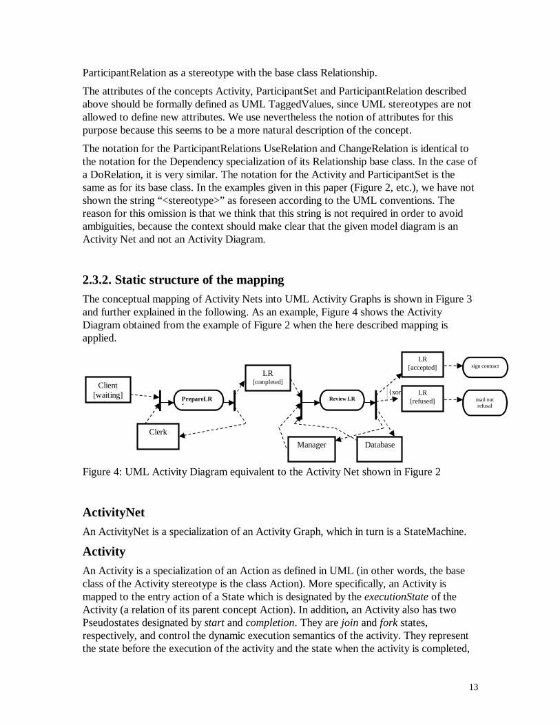
2.3.2. Static structure of the mapping
The conceptual mapping of Activity Nets into UML Activity Graphs is shown in Figure 3and further explained in the following. As an example, Figure 4 shows the ActivityDiagram obtained from the example of Figure 2 when the here described mapping isapplied.
{xorPrepareLR f
Client [waiting]
Clerk
LR [completed]
Manager
Review LR
Database
LR [refused]
LR [accepted] sign contract
mail out refusal
Figure 4: UML Activity Diagram equivalent to the Activity Net shown in Figure 2
ActivityNet
An ActivityNet is a specialization of an Activity Graph, which in turn is a StateMachine.
Activity
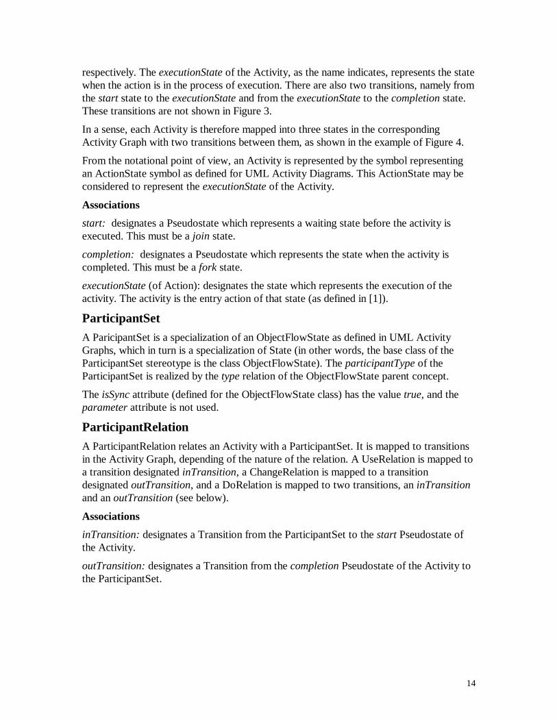
An Activity is a specialization of an Action as defined in UML (in other words, the baseclass of the Activity stereotype is the class Action). More specifically, an Activity ismapped to the entry action of a State which is designated by the executionState of theActivity (a relation of its parent concept Action). In addition, an Activity also has twoPseudostates designated by start and completion. They are join and fork states,respectively, and control the dynamic execution semantics of the activity. They representthe state before the execution of the activity and the state when the activity is completed,
14
respectively. The executionState of the Activity, as the name indicates, represents the statewhen the action is in the process of execution. There are also two transitions, namely fromthe start state to the executionState and from the executionState to the completion state.These transitions are not shown in Figure 3.
In a sense, each Activity is therefore mapped into three states in the correspondingActivity Graph with two transitions between them, as shown in the example of Figure 4.
From the notational point of view, an Activity is represented by the symbol representingan ActionState symbol as defined for UML Activity Diagrams. This ActionState may beconsidered to represent the executionState of the Activity.
Associations
start: designates a Pseudostate which represents a waiting state before the activity isexecuted. This must be a join state.
completion: designates a Pseudostate which represents the state when the activity iscompleted. This must be a fork state.
executionState (of Action): designates the state which represents the execution of theactivity. The activity is the entry action of that state (as defined in [1]).
ParticipantSet
A ParicipantSet is a specialization of an ObjectFlowState as defined in UML ActivityGraphs, which in turn is a specialization of State (in other words, the base class of theParticipantSet stereotype is the class ObjectFlowState). The participantType of theParticipantSet is realized by the type relation of the ObjectFlowState parent concept.
The isSync attribute (defined for the ObjectFlowState class) has the value true, and theparameter attribute is not used.
ParticipantRelation
A ParticipantRelation relates an Activity with a ParticipantSet. It is mapped to transitionsin the Activity Graph, depending of the nature of the relation. A UseRelation is mapped toa transition designated inTransition, a ChangeRelation is mapped to a transitiondesignated outTransition, and a DoRelation is mapped to two transitions, an inTransitionand an outTransition (see below).
Associations
inTransition: designates a Transition from the ParticipantSet to the start Pseudostate ofthe Activity.
outTransition: designates a Transition from the completion Pseudostate of the Activity tothe ParticipantSet.
15
2.3.3. Well-formedness rules
(A) Rules already mentioned in Section 2.3.2
(1) The start StateVertex of an Activity is a join Pseudostate.
(2) The start StateVertex of an Activity is connected with by a transition with theState for which the Activity is the entry action.
(3) The state for which the Activity is the entry action is an ActionState according tothe UML definition of Activity Graphs, however, the attributes of the ActionStateare not used for Activity Nets.
(4) The completion StateVertex of an Activity is a fork Pseudostate.
(5) Each Activity has a separate start and completion state.
(6) The State for which the Activity is the entry action is connected by a Transitionwith the completion StateVertex of the Activity.
(7) The isSync attribute of a ParticipantSet is true.
(8) The inTransition of a ParticipantRelation has as target the ParticipantSet to whichthe ParticipantRelation relates.
(9) The inTransition of a ParticipantRelation has as source the completionPseudostate of the Activity to which the ParticipantRelation relates.
(10) The outTransition of a ParticipantRelation has as target the ParticipantSetto which the ParticipantRelation relates.
(11) The outTransition of a ParticipantRelation has as source the completionPseudostate of the Activity to which the ParticipantRelation relates.
(B) Other rules(1) The State designated by the inState relation of a ClassifierInState which is the
participantType of a ParticipantSet must be one of the states contained in theStateMachine which describes the dynamic behavior of the Classifier whichdescribes the type of the participants in the ParticipantSet.
(2) If a given Activity has a UseRelation and a ChangeRelation with twoParticipantSets which have as participantType two ClassifierInState classes whichbelong to the same Classifier (but different states), then this Activity must be theeffect of a Transition that exists in the StateMachine of the Classifier and has assource StateVertex the inState state of the ClassifierInState associated with theUseRelation and as target StateVertex the inState state of the ClassifierInStateassociated with the ChangeRelation.
16
2.3.4. Mapping of the dynamic semantics
The following paragraphs provide some explanation of the semantic aspects of themapping described above and indicate some minor discrepancies between the semantics ofActivity Nets as defined in Section 2.2.4 and the semantics obtained from this mapping.
As explained above, an Activity is mapped onto three states in the Activity Graph: a startstate, an executionState and a completion state. The firing rules of the Activity are realizedby the start StateVertex of the Activity, which is a join Pseudostate. The inTransitions ofthe Use and Do relations of the Activity lead into this join state. Therefore objects must bepresent in the ObjectFlowStates from which these inTransitions start before the transitionleading from the start state to the executionState can be performed (according to thestandard UML semantics of Activity Graphs).
The creation of the output object instances of the action correspond to the outTransitionswhich go from the completion Pseudostate of the Activity to the ParticipantSets related bya Change or Do relation.
It is noted that the definition of the semantics of Transitions for Activity Graphs [1] statesthat fork and join Pseudostates must be well-nested according to rule #2 for PseudoStatesin Activity Graphs. This does not apply to Activity Nets. Also the semantics for guardsgiven in that paragraph does not apply to Activity Nets.
It is also noted that according to the definition of Activity Graphs, the Action representedby an Activity should be the entry action of an ActionState, and not a State (as shown inFigure 3). We have chosen not to use an ActionState at this point, but instead the moregeneral notion of a State, because the concurrency semantics defined for ActionStates isnot appropriate for Activities.
A ParticipantSet is a ObjectFlowState and inherits the semantics from that construct. InActivityNets, ObjectFlowStates are used as synch states. The semantics ofObjectFlowStates in [1] specifies FIFO ordering for the object instances located at a givenObjectFlowState. This is also the default semantics for Activity Nets, however, othersemantic options are also foreseen for Activity Nets (see Section 2.4). In [1] it ismentioned that “An object flow state may specify the parameter of an operation thatprovides its object as output, and the parameter of an operation that takes its object asinput”. This facility is not used for ActivityNet modeling.
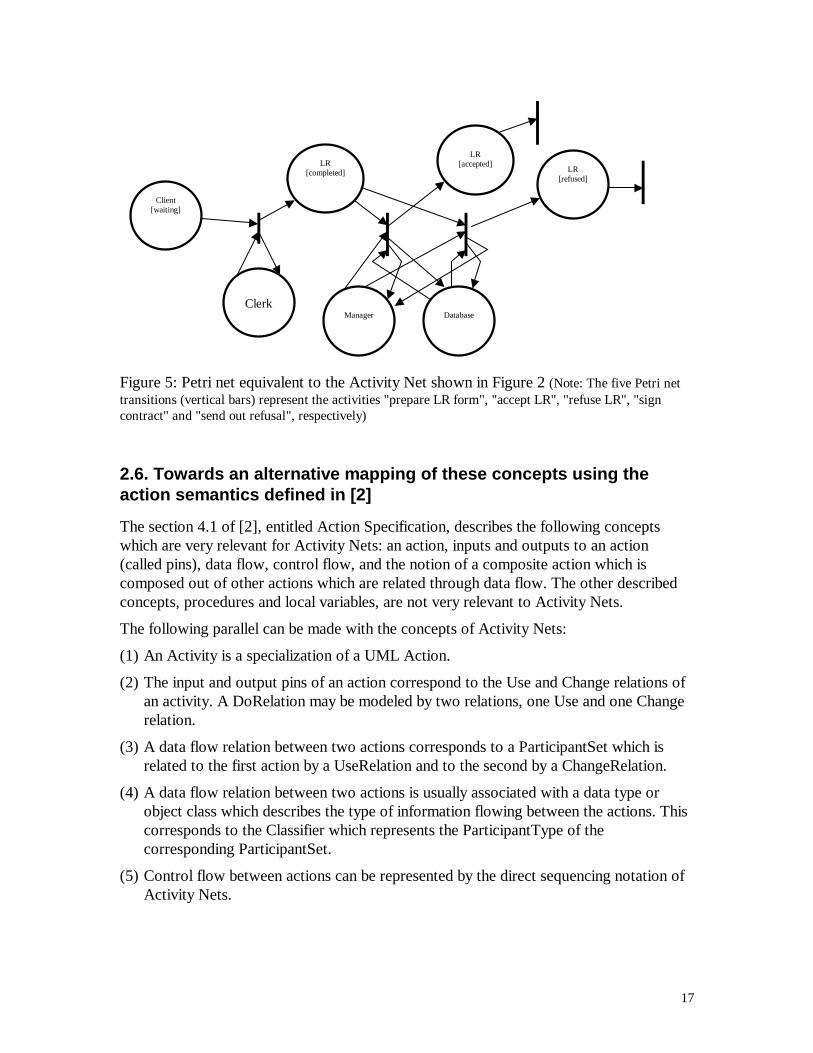
Note: The dynamic semantics of Activity Nets is equivalent to the semantics of Petri netsif one considers that an ActivityNet is a Petri net. A Petri net consists of places andtransitions which are connected by arrows. We assume the following mapping from theobjects of ActivityNet to the places and transitions of a corresponding Petri net: (a) EachParticipantSet of the net is a place of the Petri net, (b) each Activity with its start andcompletion Pseudostates is a transition of the Petri net, and (c) the inTransition andoutTransition transitions of the ParticipantRelations in the ActivityNet correspond to thearrows leading into and out of (respectively) the Petri net transitions which correspond tothe Activities related by the ParticipantRelations. As an example, Figure 5 shows a Petrinet equivalent to the Activity Net of Figure 2.
17
Client [waiting]
Clerk
LR [completed]
Manager
Database
LR [refused]
LR
[accepted]
Figure 5: Petri net equivalent to the Activity Net shown in Figure 2 (Note: The five Petri nettransitions (vertical bars) represent the activities "prepare LR form", "accept LR", "refuse LR", "signcontract" and "send out refusal", respectively)
2.6. Towards an alternative mapping of these concepts using theaction semantics defined in [2]
The section 4.1 of [2], entitled Action Specification, describes the following conceptswhich are very relevant for Activity Nets: an action, inputs and outputs to an action(called pins), data flow, control flow, and the notion of a composite action which iscomposed out of other actions which are related through data flow. The other describedconcepts, procedures and local variables, are not very relevant to Activity Nets.
The following parallel can be made with the concepts of Activity Nets:
(1) An Activity is a specialization of a UML Action.
(2) The input and output pins of an action correspond to the Use and Change relations ofan activity. A DoRelation may be modeled by two relations, one Use and one Changerelation.
(3) A data flow relation between two actions corresponds to a ParticipantSet which isrelated to the first action by a UseRelation and to the second by a ChangeRelation.
(4) A data flow relation between two actions is usually associated with a data type orobject class which describes the type of information flowing between the actions. Thiscorresponds to the Classifier which represents the ParticipantType of thecorresponding ParticipantSet.
(5) Control flow between actions can be represented by the direct sequencing notation ofActivity Nets.
18
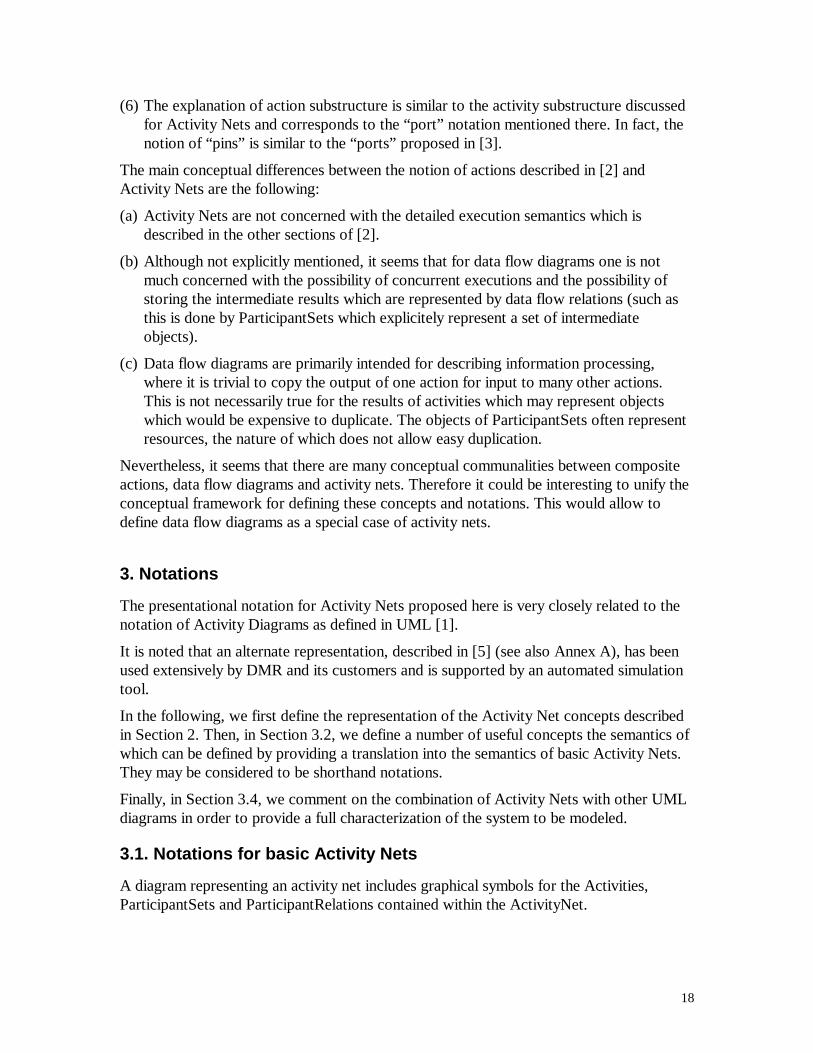
(6) The explanation of action substructure is similar to the activity substructure discussedfor Activity Nets and corresponds to the “port” notation mentioned there. In fact, thenotion of “pins” is similar to the “ports” proposed in [3].
The main conceptual differences between the notion of actions described in [2] andActivity Nets are the following:
(a) Activity Nets are not concerned with the detailed execution semantics which isdescribed in the other sections of [2].
(b) Although not explicitly mentioned, it seems that for data flow diagrams one is notmuch concerned with the possibility of concurrent executions and the possibility ofstoring the intermediate results which are represented by data flow relations (such asthis is done by ParticipantSets which explicitely represent a set of intermediateobjects).
(c) Data flow diagrams are primarily intended for describing information processing,where it is trivial to copy the output of one action for input to many other actions.This is not necessarily true for the results of activities which may represent objectswhich would be expensive to duplicate. The objects of ParticipantSets often representresources, the nature of which does not allow easy duplication.
Nevertheless, it seems that there are many conceptual communalities between compositeactions, data flow diagrams and activity nets. Therefore it could be interesting to unify theconceptual framework for defining these concepts and notations. This would allow todefine data flow diagrams as a special case of activity nets.
3. Notations
The presentational notation for Activity Nets proposed here is very closely related to thenotation of Activity Diagrams as defined in UML [1].
It is noted that an alternate representation, described in [5] (see also Annex A), has beenused extensively by DMR and its customers and is supported by an automated simulationtool.
In the following, we first define the representation of the Activity Net concepts describedin Section 2. Then, in Section 3.2, we define a number of useful concepts the semantics ofwhich can be defined by providing a translation into the semantics of basic Activity Nets.They may be considered to be shorthand notations.
Finally, in Section 3.4, we comment on the combination of Activity Nets with other UMLdiagrams in order to provide a full characterization of the system to be modeled.
3.1. Notations for basic Activity Nets
A diagram representing an activity net includes graphical symbols for the Activities,ParticipantSets and ParticipantRelations contained within the ActivityNet.
19
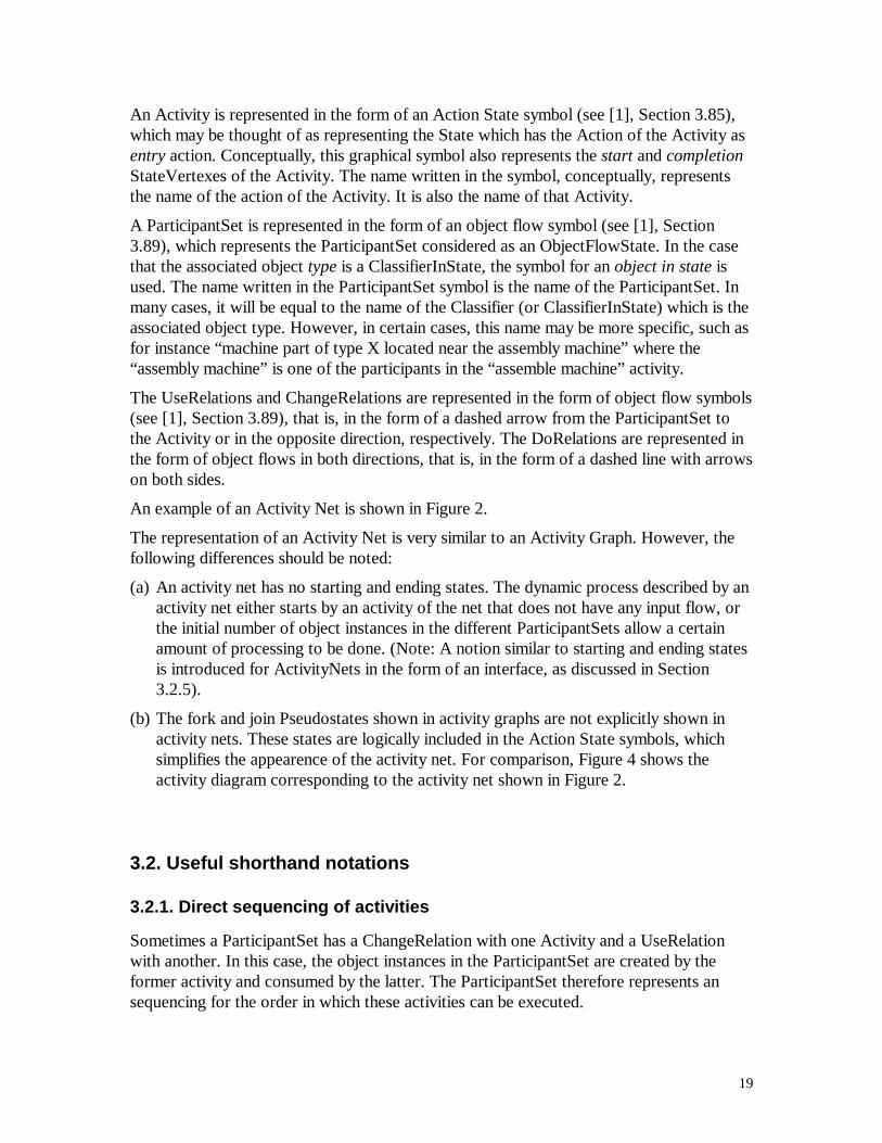
An Activity is represented in the form of an Action State symbol (see [1], Section 3.85),which may be thought of as representing the State which has the Action of the Activity asentry action. Conceptually, this graphical symbol also represents the start and completionStateVertexes of the Activity. The name written in the symbol, conceptually, representsthe name of the action of the Activity. It is also the name of that Activity.
A ParticipantSet is represented in the form of an object flow symbol (see [1], Section3.89), which represents the ParticipantSet considered as an ObjectFlowState. In the casethat the associated object type is a ClassifierInState, the symbol for an object in state isused. The name written in the ParticipantSet symbol is the name of the ParticipantSet. Inmany cases, it will be equal to the name of the Classifier (or ClassifierInState) which is theassociated object type. However, in certain cases, this name may be more specific, such asfor instance “machine part of type X located near the assembly machine” where the“assembly machine” is one of the participants in the “assemble machine” activity.
The UseRelations and ChangeRelations are represented in the form of object flow symbols(see [1], Section 3.89), that is, in the form of a dashed arrow from the ParticipantSet tothe Activity or in the opposite direction, respectively. The DoRelations are represented inthe form of object flows in both directions, that is, in the form of a dashed line with arrowson both sides.
An example of an Activity Net is shown in Figure 2.
The representation of an Activity Net is very similar to an Activity Graph. However, thefollowing differences should be noted:
(a) An activity net has no starting and ending states. The dynamic process described by anactivity net either starts by an activity of the net that does not have any input flow, orthe initial number of object instances in the different ParticipantSets allow a certainamount of processing to be done. (Note: A notion similar to starting and ending statesis introduced for ActivityNets in the form of an interface, as discussed in Section3.2.5).
(b) The fork and join Pseudostates shown in activity graphs are not explicitly shown inactivity nets. These states are logically included in the Action State symbols, whichsimplifies the appearence of the activity net. For comparison, Figure 4 shows theactivity diagram corresponding to the activity net shown in Figure 2.
3.2. Useful shorthand notations
3.2.1. Direct sequencing of activities
Sometimes a ParticipantSet has a ChangeRelation with one Activity and a UseRelationwith another. In this case, the object instances in the ParticipantSet are created by theformer activity and consumed by the latter. The ParticipantSet therefore represents ansequencing for the order in which these activities can be executed.
20
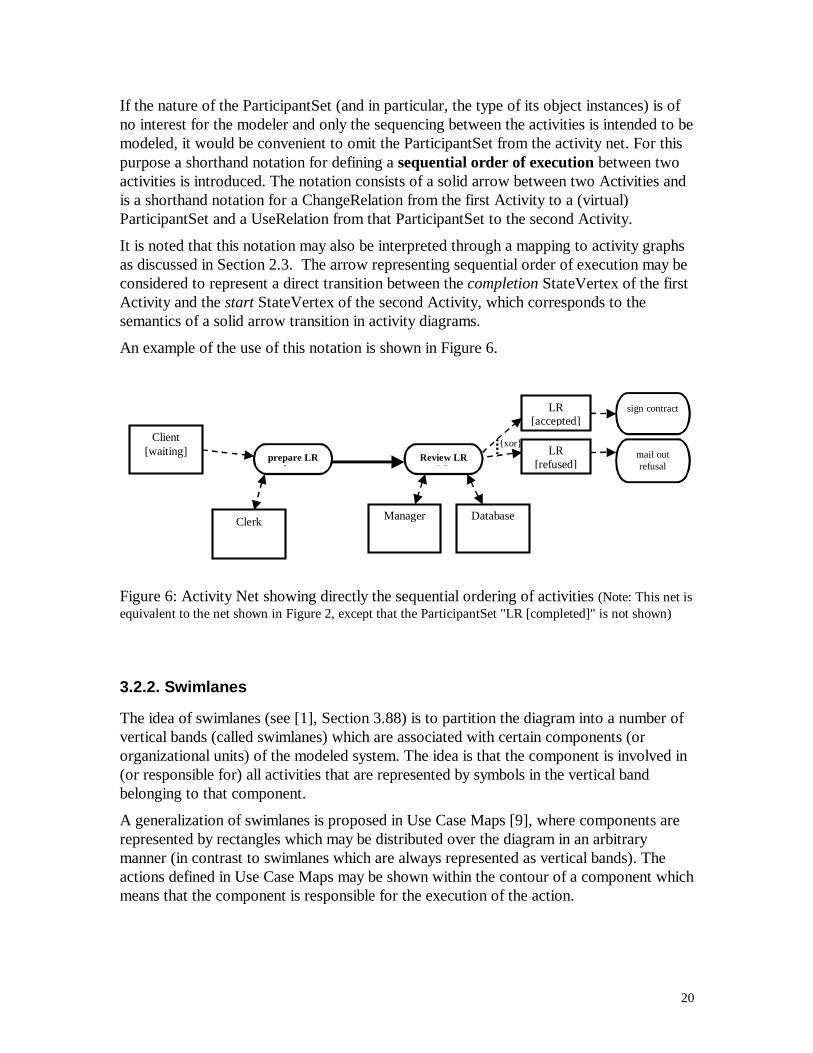
If the nature of the ParticipantSet (and in particular, the type of its object instances) is ofno interest for the modeler and only the sequencing between the activities is intended to bemodeled, it would be convenient to omit the ParticipantSet from the activity net. For thispurpose a shorthand notation for defining a sequential order of execution between twoactivities is introduced. The notation consists of a solid arrow between two Activities andis a shorthand notation for a ChangeRelation from the first Activity to a (virtual)ParticipantSet and a UseRelation from that ParticipantSet to the second Activity.
It is noted that this notation may also be interpreted through a mapping to activity graphsas discussed in Section 2.3. The arrow representing sequential order of execution may beconsidered to represent a direct transition between the completion StateVertex of the firstActivity and the start StateVertex of the second Activity, which corresponds to thesemantics of a solid arrow transition in activity diagrams.
An example of the use of this notation is shown in Figure 6.
{xor}
prepare LR f
Client [waiting]
Clerk Manager
Review LR LR
Database
LR [refused]
LR [accepted]
mail out refusal
sign contract
Figure 6: Activity Net showing directly the sequential ordering of activities (Note: This net isequivalent to the net shown in Figure 2, except that the ParticipantSet "LR [completed]" is not shown)
3.2.2. Swimlanes
The idea of swimlanes (see [1], Section 3.88) is to partition the diagram into a number ofvertical bands (called swimlanes) which are associated with certain components (ororganizational units) of the modeled system. The idea is that the component is involved in(or responsible for) all activities that are represented by symbols in the vertical bandbelonging to that component.
A generalization of swimlanes is proposed in Use Case Maps [9], where components arerepresented by rectangles which may be distributed over the diagram in an arbitrarymanner (in contrast to swimlanes which are always represented as vertical bands). Theactions defined in Use Case Maps may be shown within the contour of a component whichmeans that the component is responsible for the execution of the action.
21
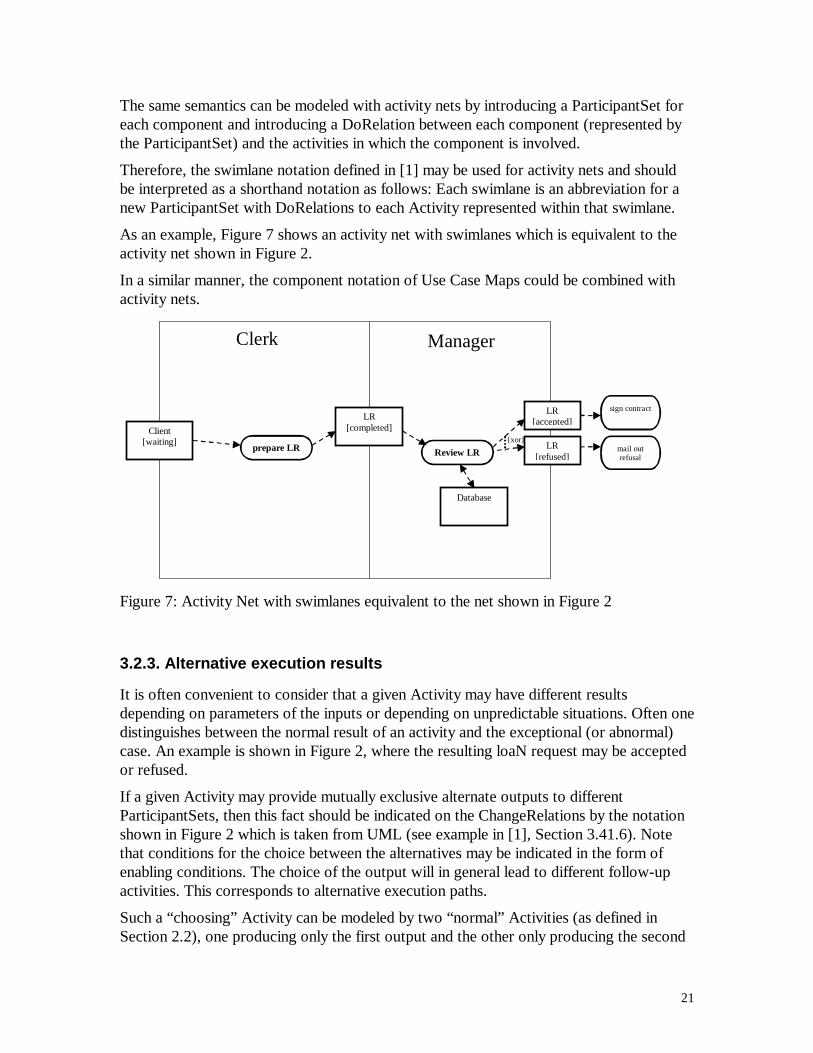
The same semantics can be modeled with activity nets by introducing a ParticipantSet foreach component and introducing a DoRelation between each component (represented bythe ParticipantSet) and the activities in which the component is involved.
Therefore, the swimlane notation defined in [1] may be used for activity nets and shouldbe interpreted as a shorthand notation as follows: Each swimlane is an abbreviation for anew ParticipantSet with DoRelations to each Activity represented within that swimlane.
As an example, Figure 7 shows an activity net with swimlanes which is equivalent to theactivity net shown in Figure 2.
In a similar manner, the component notation of Use Case Maps could be combined withactivity nets.
{xor} prepare LR Review LR
Database
Clerk Manager
Client [waiting]
LR [completed]
LR [refused]
LR [accepted]
mail out refusal
sign contract
Figure 7: Activity Net with swimlanes equivalent to the net shown in Figure 2
3.2.3. Alternative execution results
It is often convenient to consider that a given Activity may have different resultsdepending on parameters of the inputs or depending on unpredictable situations. Often onedistinguishes between the normal result of an activity and the exceptional (or abnormal)case. An example is shown in Figure 2, where the resulting loaN request may be acceptedor refused.
If a given Activity may provide mutually exclusive alternate outputs to differentParticipantSets, then this fact should be indicated on the ChangeRelations by the notationshown in Figure 2 which is taken from UML (see example in [1], Section 3.41.6). Notethat conditions for the choice between the alternatives may be indicated in the form ofenabling conditions. The choice of the output will in general lead to different follow-upactivities. This corresponds to alternative execution paths.
Such a “choosing” Activity can be modeled by two “normal” Activities (as defined inSection 2.2), one producing only the first output and the other only producing the second
22
one. Both of these “normal” Activities would have the same UseRelations andDoRelations with other ParticipantSets as the “choosing” Activity. For given input objectinstances, only one of these Activities will be executed and will provide its specific output.The choice may depend on some enabling conditions which may be functions of theparameters of the input objects.
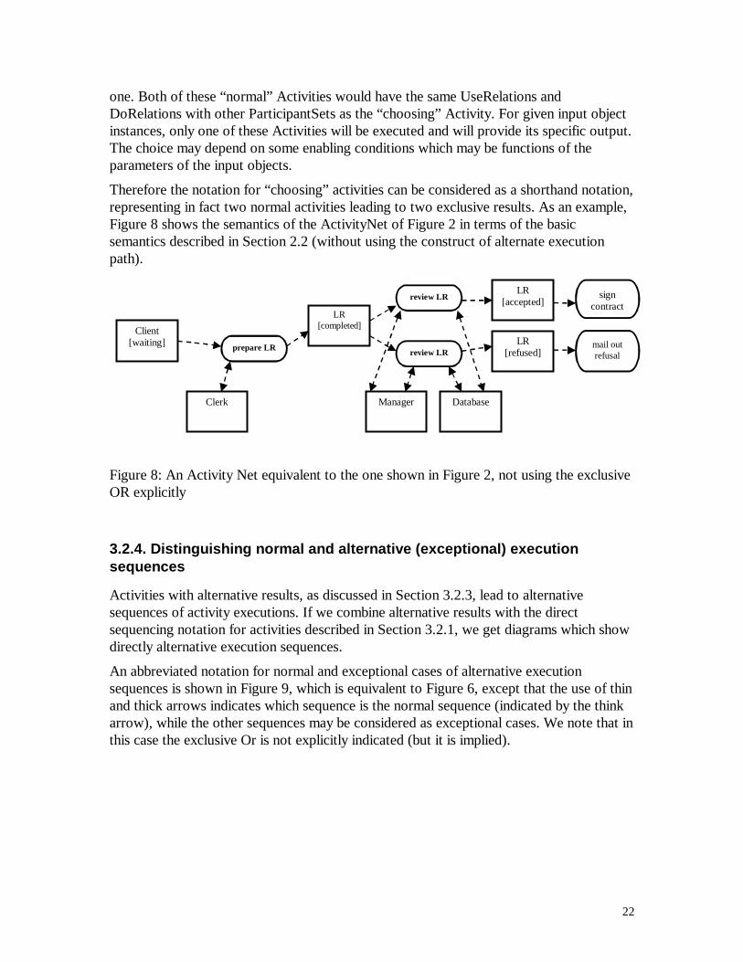
Therefore the notation for “choosing” activities can be considered as a shorthand notation,representing in fact two normal activities leading to two exclusive results. As an example,Figure 8 shows the semantics of the ActivityNet of Figure 2 in terms of the basicsemantics described in Section 2.2 (without using the construct of alternate executionpath).
prepare LR
Client [waiting]
Clerk
LR [completed]
Manager
review LR
Database
LR [refused]
LR [accepted] review LR
mail out refusal
sign contract
Figure 8: An Activity Net equivalent to the one shown in Figure 2, not using the exclusiveOR explicitly
3.2.4. Distinguishing normal and alternative (exceptional) executionsequences
Activities with alternative results, as discussed in Section 3.2.3, lead to alternativesequences of activity executions. If we combine alternative results with the directsequencing notation for activities described in Section 3.2.1, we get diagrams which showdirectly alternative execution sequences.
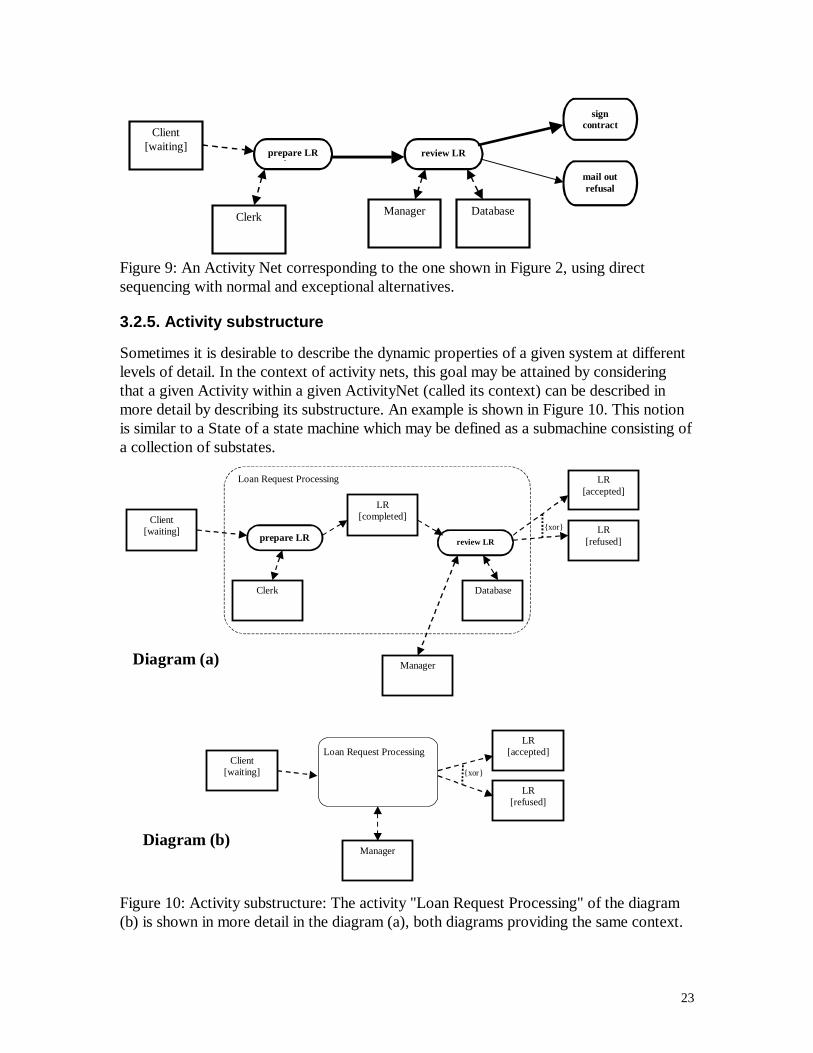
An abbreviated notation for normal and exceptional cases of alternative executionsequences is shown in Figure 9, which is equivalent to Figure 6, except that the use of thinand thick arrows indicates which sequence is the normal sequence (indicated by the thinkarrow), while the other sequences may be considered as exceptional cases. We note that inthis case the exclusive Or is not explicitly indicated (but it is implied).
23
prepare LR f
Client [waiting]
Clerk Manager
review LR
Database
mail out refusal
sign contract
Figure 9: An Activity Net corresponding to the one shown in Figure 2, using directsequencing with normal and exceptional alternatives.
3.2.5. Activity substructure
Sometimes it is desirable to describe the dynamic properties of a given system at differentlevels of detail. In the context of activity nets, this goal may be attained by consideringthat a given Activity within a given ActivityNet (called its context) can be described inmore detail by describing its substructure. An example is shown in Figure 10. This notionis similar to a State of a state machine which may be defined as a submachine consisting ofa collection of substates.
{xor}
{xor}
Loan Request Processing
prepare LR
Client [waiting]
Clerk
LR [completed]
Manager
review LR
Database
LR [refused]
LR [accepted]
Client [waiting]
Manager
LR [refused]
LR [accepted]
Loan Request Processing
Diagram (a)
Diagram (b)
Figure 10: Activity substructure: The activity "Loan Request Processing" of the diagram(b) is shown in more detail in the diagram (a), both diagrams providing the same context.
24
Definition: We call the ParticipantRelations of an Activity within an ActivityNet the interfaceof the Activity in the context of this ActivityNet.
Definition: We call an ActivityNet with an interface a normal ActivityNet (as defined inSection 2.2) to which we add one or more ParticipantRelations for which the end-pointdesignating a ParticipantSet is not assigned to any ParticipantSet of the ActivityNet. We callthese partially assigned ParticipantRelations the interface of the ActivityNet.
In the case of the example of Figure 10, the interface of the activity “Loan RequestProcessing” consists of the following ParticipantRelations: a UseRelation with a “Client[waiting]”, a DoRelation with a “Manager”, and ChangeRelations with a “LR [accepted]” anda “LR [refused]”, which are mutually exclusive .
Replacing an activity by an activity net: Given an Activity A within the context of anActivityNet N and another ActivityNet N’ with an interface, then A may be replaced in N byN’ if there is a one-to-one mapping between the ParticipantRelations in the interface of A inthe context of N and theParticipantRelations in the interface of N’. In this case we also say thatN’ is a refined (more detailed) view of A.
Inversely, we may consider a region of an ActivityNet N which is such that its border only cutsParticipantRelations between some Activity which is inside the region and some ParticipantSetwhich is outside the region. In order to obtain a more simple (less detailed) model of thesystem, this region may be replaced by a single Activity and all ParticipantRelations that are cutby the border of the region will be connected to that new Activity. The resulting ActivityNet iscalled a less detailed view of N.
Concerning the notation for representing the interface of an ActivityNet, there are differentpossible approaches such a the following.
(a) To use the notation for submachines of UML Statechart diagrams: A notation similarto Submachine States of UML ([1], Section 3.82) lead to examples of the form shownin Figure 11. This notation has the disadvantage that it does not support a black-boxview for the less detailed description; one has to refer to certain “components” of theactivity, which is in conflict with the notion of abstraction.
(b) To define the interface through the introduction of “ports”, “pins” or otherplaceholders: The ports introduced for RT-UML [3] allow for a black-box view at theabstract level and provide sufficient information for a proper checking of the“interfaces”. A similar concept, called a “in”, has been introduced in the draft of theUML Action Semantics [2]. We suggest to identify each ParticipantRelation of theinterface by a “port”, and obtain the example shown in Figure 12.
(c) To have no specific notation for the interface: In this case the diagram showing thedetailed view of an Activity A in the context of an ActivityNet N must include allelements of N which make up the immediate context of A. This approach has beentaken in [5].
The approach (b) is preferable, since it provides for a clear definition of the interface of anactivity and therefore simplifies the checking of replacement compatibility and promotes ablack-box view of activities.

25
{xor}
{xor} Client
[waiting]
Manager
LR [refused]
LR [accepteLoan Request
Processing
prepare LR
Clerk
LR [completed]
review LR
Database
Loan Request Processing
ac
d
b
b
c d
a
(a)
(b)
Figure 11: Activity substructure notation taken from UML Statemachines: Same exampleas in Figure 10. Diagram (a) shows the activity substructure and diagram (b) shows howthe activity can be used in its context.
{xor}
Client [waiting]
Manager
LR [refused]
LR [accepted]
prepare LR
Clerk
LR [completed]
review LR LR
Database
Loan Request Processing
accepted
refused
Loan Request Processing
prepare LR review LR refused
accepted
{xor}
(a)
(b)
Figure 12: Activity substructure notation using ports: Same example as in Figure 10.Diagram (a) shows the activity substructure (including ports a, b, c and d) and diagram (b)shows how the activity can be used in its context.
26
3.3. Using activity nets with other UML diagrams
For describing a given workflow architecture, activity nets are usually complemented withUML Class Diagrams to describe the different types of Participants that are part of theworkflow architecture. Depending on the application domain, different class hierarchiesmay be appropriate. For example, DMR’s OPAL modeling guide [5], describes in Chapter4 a hierarchy of Participant types which are suitable for the modeling of organizationalarchitectures and workflows. A different set of object classes is defined in [13] for use indescriptions of software engineering processes. Another example is a rudimentary set ofparticipant types defined in the UML Profile for Business Modeling (see [1], Chapter 4,Part 2).
Sometimes it may also be useful to use Class-Relationship diagrams to show containmentrelations, dependencies, transformation rules etc. (in addition to the Participant Relationsalready included in the Activity Nets).
State Diagrams describing the dynamic behavior of the participant object classes may alsobe included. However, they are already partly implied by the Activity Nets if the latter useClassifierInState information for characterizing the objects in the ParticipantSets.Complete state diagrams seem to be more suitable for more implementation-orientedsystem designs which will be developed during a later phase of the system developmentprocess.
27
References
[1] OMG Unified Modeling Language Specification, Version 1.3, June 1999.
[2] UML Action Semantics (Draft), Action Semantics Consortium, 29 Jun 2000.
[3] UML-RT: A Profile for Modeling Complex Real-Time Architectures, Bran Selic,ObjecTime, Draft Version Dec. 12 1999.
[4] White Paper on the Profile mechanism, Analysis and Design Platform Task Force,OMG Document ad/99-04-07.
[5] OPAL Modeling and Simulation, DMR Architecture Lab, Technics Guide, Part 1.
[6] Conceptual Framework for Analysing Business Infrastructure as an IntegratedDynamic Model, by F. H. Stanley, Research and Development, DMR Group Inc.,Montreal, 1992?
[7] A new approach to architectureal modeling and dynamic analysis of informationsystems and business processes, by G.v. Bochmann, A.C. Debaque, R. Dssouli, A. Jaoua,R.K. Keller, N. Rico and F. Saba, Technical Report, CRIM, Montreal, Dec/ 1992.
[8] The Macrotec Toolset for CASE-based Business Modeling, R.K. Keller et al., CRIM,Montreal, published ? 1994?
[9] On the Extension of UML with Use Case Maps Concepts, by D. Amyot (University ofOttawa) and G. Mussbacher (Mitel, Ottawa), to be presented at the UML conference,Oct. 2000.
[10] K. Jensen, Coloured Petri Nets - Basic Concepts, Analysis Methods and PracticalUse - Volume 1, EATCS Monographs on Theoretical Computer Science, Springer-Verlag, 1992.
[11] K.S. Trivedi, J.K. Muppula, S.P. Woolet and B.R. Haverkort, Compositeperformance and dependability analysis, Performance Evaluation, 14 (3-1), pp. 197-215,1992.
[12] OMG document: Workflow Management Facility, Convenience Documentcombining dtc/99-07-05 and dtc/2000-02-03 (WF RTF 1.3 Report), 14 February 2000.
[13] OMG document ad/2000-05-01: Software Process Engineering (SPE) ManagementRFP, Initial Submission, Fujitsu/DMR.