a technical guide to designing application-ready … and manufacturing ... support a high-density,...
TRANSCRIPT
A Technical Guide to Designing Application-Ready Military Computing Solutions
A Trenton Systems White Paper

A Technical Guide to Designing Application-Ready Military Computing Solutions
Introduction Military computing solutions have played an increasingly vital role in supporting combat operations around the globe. From command and control centers to ground vehicle applications, manned and unmanned airborne missions, as well as surface and undersea deployments, advances in computing power features and a growing number of transducers sensing capabilities have translated into greater effectiveness and enhanced situational awareness.
Despite the introduction of off-the-shelf personal computers in the 1970s and 1980s, the majority of systems destined for military use incorporated custom hardware, built from the ground up to meet the needs of a single application. These proprietary solutions were rarely used in other programs, resulting in increased design, manufacture, deployment and maintenance costs.
The 1990s witnessed a major push within the Federal government to utilize COTS computing solutions whenever possible to address the needs of military applications. High expectations of increased cost savings and decreased lead times were based on the procurement and manufacturing methodologies utilized in the volume production of commercial-off-the-shelf business and personal computers.
While the adoption of commercial hardware and standard operating systems have lowered costs and shortened development cycles, the stark reality of deploying such computers in harsh environments, while meeting the challenging constraints of SWaP-C (size, weight and power plus cooling or cost), has required a modified approach to computing system design for these military applications.
Application-Ready Military Computing Solutions
What has become clear is the need to create COTS solutions that are both rugged and configurable. These computing platforms adhere to industry standards while also satisfying a unique set of critical system requirements. This application-ready methodology includes customized enclosures, modified board-level sub-systems, unique power supply options, and complete control of the system BIOS.
Figure 1 – Mobile Ground Vehicle Station for UAV Control and Tracking
Issues such as thermal management, shock & vibration, electromagnetic interference (EMI), humidity, dust, salt and fog must be accounted for within the sound principles of systems engineering to ensure that any computing solution designed for mission-critical C4ISR (Command, Control, Communications, Computers, Intelligence, Surveillance and Reconnaissance) applications operate reliably.
With a long history of designing and manufacturing long-life board-level computer products to serve a wide range of industries, including government & defense, industrial automation, and communications, Trenton Systems understands the need for reliable,

A Technical Guide to Designing Application-Ready Military Computing Solutions
high-performance computing solutions based on proven standard hardware and software architectures, that can be modified to meet individual specifications.
This technical guide explores the various factors that must be taken into account when crafting these application-ready computing solutions to meet the needs of challenging military applications. This systematic design methodology is examined in greater detail by discussing the following attributes in greater detail: System Engineering, Electrical and Electronic design, Mechanical Design, Manufacturing, System BIOS Configuration, and System Integration. By reviewing your military computing application with the afore mentioned design segments in mind, a custom design can be launched with little surprises and a greater likelihood of success.
Systems Engineering
When designing complex military computing platforms, the key to maximizing system performance, reliability and compatibility is an understanding of how mechanical enclosures, electrical components and sub-systems interact (thermally, electrically and how they physical fit) with each other once the system is fully integrated and operating in a variety of demanding environments.
Figure 2 – Ground Vehicle Mounted Computer
Maintaining control over the design and manufacture of board-level sub-systems, such as single board computers, backplanes and embedded motherboards, as well as the computer system BIOS, provides the foundation for a systems engineering approach to creating application-ready computing solutions.
A coordinated team of experienced electrical, mechanical and BIOS engineers utilizing a concurrent engineering methodology will ensure that system performance, compatibility and reliability are accounted for during the design phase, well before the production cycle begins. Designing with military applications in mind allows the customer to choose from a range of single or multi-core processors which accommodate various clock speeds, memory configurations, I/O interfaces and operating systems.
This systems-level methodology also incorporates advanced processor-related technologies, such as Intel® Advanced Vector Extensions, Intel® Turbo Boost Technology, Intel® Virtualization Technology and Intel® Hyper-Threading Technology all of which support a high-density, high-performance approach to creating extensible, application-ready platforms.
Having a detailed level of knowledge of the above computing architecture coupled with the board design and manufacture processes to the final system integration, provides superior support capability should issues arise once the systems have been deployed, and the use of validated technology building blocks gives end users the ability to perform upgrades in the field.

A Technical Guide to Designing Application-Ready Military Computing Solutions
Systems Engineering Considerations
• Slot Configuration • Third Party Cards • Operating Systems • Bus Bandwidth • Power Requirements • Shock & Vibration • Electromagnetic Interference • Thermal Management • System BIOS Compatibility • Height & Depth Constraints • Weight Restrictions
Electrical and Electronic Design
Multi-layer printed circuit board design and manufacture continues to be a challenge for engineering in this day of high-speed processor interconnects and network interfaces combined with the need for ever increasing levels of component density in order to maximize feature sets and performance using a fixed amount of PCB real estate.
Figure 3 – Dual-Processor SBC
Sub-system board designs must maintain signal integrity with high-speed interfaces such as CPU-to-CPU interconnects, DDR3/DDR4 memory, PCI Express 2.0/3.0 & 10/100/1000Base-T Ethernet while addressing power distribution, signal trace routing and thermal management issues, as well as adhering to stringent UL/CSA and IEEE agency standards.
Figure 4 – PCI Express 3.0 Backplane
Application-ready military computing solutions typically need to operate for extended periods of time, far longer than most commercial systems, which means that processor and memory upgrades must be accommodated within any product family. The combination of single board computers and backplanes extends the system engineering concept to include replacement of the SBC with upgraded technology, movement to a new backplane design which features a different slot configuration, or both.
In the military arena such designs must also take into account the fact that systems are often deployed in environments which are susceptible to shock, vibration, heat, humidity, blowing dust and EMI issues, and must operate around the clock while maintaining peak performance and reliability.
Electrical Design Considerations
• Signal Trace Routing and Xtalk Parameters
• Ground Isolation Issues • Signal Return Currents • Trace Resistance and Target
Characteristic Impedance • Stray Capacitance • Stray Inductance • Dielectric Absorption and Insertion Loss • Logic Noise

A Technical Guide to Designing Application-Ready Military Computing Solutions
Mechanical Design
Military enclosures designed to accommodate single board computers and backplanes or embedded motherboards come in a range of form factors, from the standard 19” rackmount chassis, in 1U to 6U heights, to shelfmount, wallmount, benchtop and open frame configurations. Regardless of how well the electronic sub-systems are designed and manufactured, system packaging is critical when crafting solutions for military deployment.
Figure 5 – MIL-STD-810 Enclosure Design
Even the most basic system enclosure must withstand levels of shock, vibration and heat not found in commercial environments. Figure 6 shows a typical system airflow evaluation chart for a rackmount computer design.
Figure 6 – Airflow Evaluation Chart
Military systems must provide the requisite structural integrity while meeting the conflicting objectives of Size, Weight & Power (SWaP). Thermal characteristics must be understood for each system configuration in order to provide proper cooling under extreme conditions. The infra-red image in figure 7 illustrates the thermal profile of a system. This and other test data are used to make refinements to the system design.
Figure 7 – Thermal Profile Image
Standard products in each of these packaging options can fulfill a wide variety of requirements, but in many cases customer-specific enclosure modifications are needed in order to satisfy a unique set of specifications based on program or application needs. This requires an engineering approach which satisfies the need for fast delivery COTS solutions, while providing a foundation for modifications to address a wide range of situations.
Once again, the process of designing such application-ready solutions requires in-depth knowledge of the board-level sub-systems that will be used to create an integrated platform that can survive in the harsh environmental conditions present in airborne, shipboard and undersea deployments.

A Technical Guide to Designing Application-Ready Military Computing Solutions
Mechanical Design Considerations
• Structural Integrity • Shock & Vibration • Thermal Characteristics and Subsystem
Thermal Profiles • Fan & Filter Placement • Electromagnetic Interference • System Power Requirements • Hard Drive & DVD Mounting • Backplane Slot Configuration • I/O Card Hold Down Brackets • Front & Rear I/O Port Connections • Cold Rolled Steel vs. Aluminum • Size, Weight & Power (SWaP) • Paint, Power Coating, Electroplating • FCC, UL, CE Agency Requirements • MIL-STD 167-1, 461F, 810G, 901D
Manufacturing
While many companies have moved their circuit board design and manufacturing offshore, there are inherent advantages to engineering and building such critical sub-systems in the United States using state-of-the-art ISO 9001:2008 certified facilities that adhere to rigorous quality control standards.
Maintaining control of the manufacturing process provides the customer with a “trusted supply chain” that mitigates important issues such as tampering and counterfeiting, while utilizing modern in-circuit test equipment and programmable optical inspection stations ensures the highest level of quality and reliability. This capability also provides continuity, from prototype to production and service or repair requirements once systems are in the field.
Figure 8 – Inside a Surface Mount Machine at Trenton’s Utica, NY Manufacturing Plant
Surface Mount Process
• Lead placement down to 12 mil centers @ 100,000 cph
• Placement accuracy (+/- 0.030 mm @ 3 Sigma, CPK> 1.00)
• Stencil printer repeatability ( +/- 0.0125 mm @ 6 Sigma)
• Speedline MPM Momentum® Stencil Printers
• Fuji XPF-L High-Speed Multipurpose Mounters
Figure 9 – Programing screen for a parts placement machine
• ELECTROVERT® Omni Series 10-Zone Reflow Ovens
• McDry™ Low-Humidity Storage Cabinets
• Air–Vac ONYX 29 Hot Air Rework Station

A Technical Guide to Designing Application-Ready Military Computing Solutions
Figure 10 – Inside a Wave Solder Machine at Trenton - Utica
Wave Solder & Through Hole Assembly
• ELECTROVERT® Vectra™ Wave Soldering System
• ELECTROVERT® Econopak® Plus tin/lead wave solder
• Universal Instruments VCD Single Head 8 Axial Lead Inserter
• Dynapert Axial Lead Sequencer • Autosplice Pin Insertion Equipment • Socket and Eyeletter Applicator
Equipment • Component Lead Forming Machines
Figure 11 – Board Cleaning System
Printed Circuit Assembly Cleaning
• TREK™ Triton IV MIL Aqueous Electronics Assembly Cleaning System
• Ato-Tech Chemcut Aqueous Cleaner • Aqueous Technologies Sponified Wash
System • Alpha Metals Ionograph 500M SMD II
Ionic Contamination Tester
Specialized Equipment & Services
• Camalot/SCS 4398 Conformal Coating System
• SCS Precision UVC Ultraviolet Conformal Coat Cure Unit
• AMP 3 Ton Press-Fit Connector Press • Aegis iLaunch New Product Introduction
Software • In-House Test Development, Tooling
Design & Logistical Support

A Technical Guide to Designing Application-Ready Military Computing Solutions
System BIOS Control
Beyond the complexities of designing and manufacturing board-level sub-systems and enclosures, engineering an application-ready computing solution relies on the BIOS (Basic Input/Output System), and in military applications, technical issues often arise that require BIOS modifications in order to achieve required levels of performance and functionality. System BIOS determines the sequence in which devices are initialized and configuration commands initiated. While every computer system is designed with a standard version of the system BIOS, the inclusion of high performance graphics sub-systems, GPGPU computing cards, analog & digital data acquisition cards, virtualization technology or network interfaces, often require BIOS modifications.
Figure 12 – BIOS Setup Screen Sample
System BIOS Settings
• System Launch Settings • Boot Option Priorities • PCI Sub-System Configuration • CPI Settings, CPU Configuration • SATA/IDE Configuration • Super IO Configuration
• Password Protection • Serial Port Addresses • Parallel Port Address • USB Configuration • CPU Configuration • PCH Configuration
Common System BIOS Modifications
1) Change Standard Defaults – From changing processor operational parameters to device interface types, this is our most common custom BIOS request and one of the simplest to implement. The payback can be enormous in terms of simplifying the end user system deployment process. 2) Increase Device Bus Capacity – For customers with a lot of I/O cards in their system, this custom BIOS change can be a lifesaver in terms of preventing unnecessary hardware expenditures. 3) Match Specific IRQs – Sometimes certain system components must reside in precise system locations within memory. Changing the IRQ to match the needs of the system sub-component can save hours of trouble shooting and work around headaches. 4) Custom Retry Logic – Sometimes a specific combination of I/O cards requires changes in the BIOS retry logic. A BIOS change like this can prevent system lock ups during data traffic bursts along the system’s I/O communication interface bus. 5) Adding booting delays – Legacy peripheral I/O cards sometimes have problems booting in a system with the latest multi-core processors. This custom BIOS change enables the cards to boot in the correct sequence and save the costs of re-engineering in a new card that may not meet system requirements. 6) Change Reset Pulses – Adding extra reset pulses within the BIOS sometimes enables a customer to prevent having to change an I/O card model type due to system initialization issues.
A Technical Guide to Designing Application-Ready Military Computing Solutions
7) Modifying Memory or I/O Resource Requests – Frankly I/O cards do weird things when requesting system memory or I/O resources. Oftentimes the requests make no sense and cause system misbehavior that can be eliminated by making a BIOS change that ignores unnecessary resource requests. 8) Changing Boot Priority – Some customer systems require a specific boot priority in the event that the bootable device configuration is changed. This is a simple way to meet these requirements without incurring undue re-engineering expenses.
9) Reduce System Boot Time - When system boot time is a critical factor BIOS settings can play a role. For example, setting boot priority to the hard disk and disabling booting from DVD drives, USB ports or network can save precious seconds. Launching only those drivers necessary for reaching the boot target can also reduce boot time.
System Integration
System integration represents the final step in the process of creating an application-ready computing solution, and unlike off-the-shelf commercial-grade products designed to operate in benign locations, building rugged systems that will be deployed in adverse environments requires different integration processes to ensure long-term, reliable operation.
Figure 13 – Transit Case Integration
A thorough understanding of shock & vibration, as well as thermal management issues, is required to ensure that system cards and drives are installed in the most advantageous position, properly seated and secured, and cabled in such a way that connections are sound and air flow is unobstructed.
System Integration Considerations
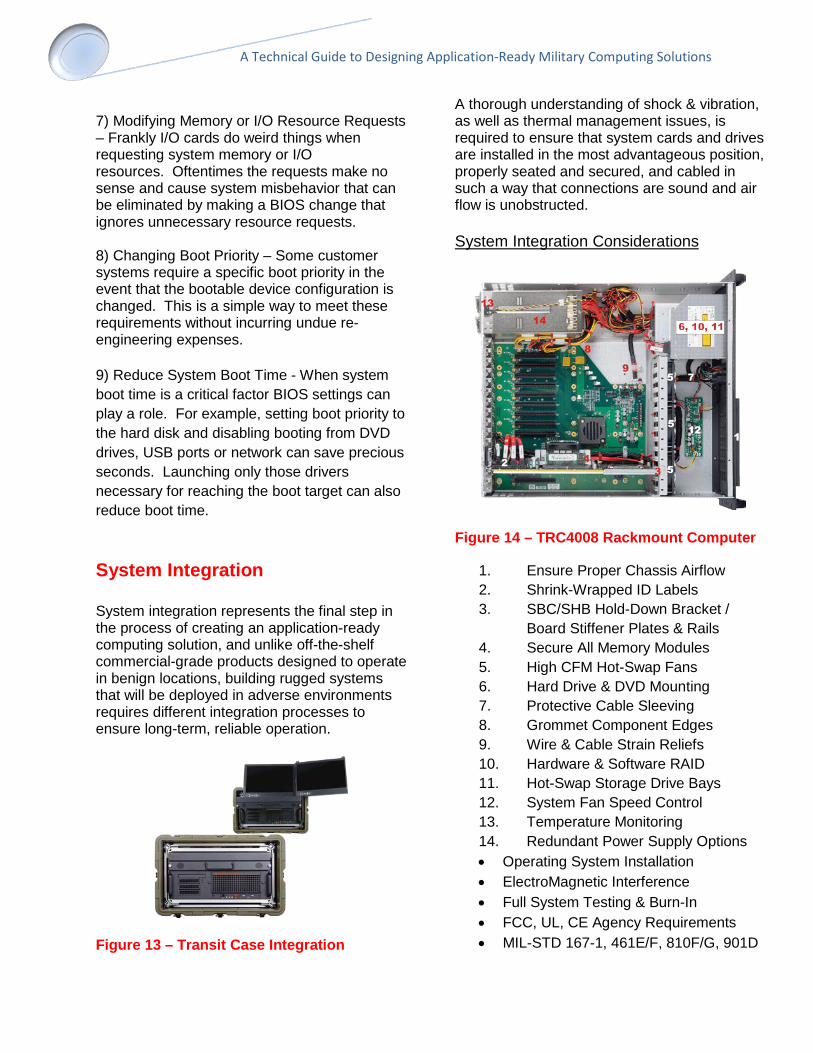
Figure 14 – TRC4008 Rackmount Computer
1. Ensure Proper Chassis Airflow 2. Shrink-Wrapped ID Labels 3. SBC/SHB Hold-Down Bracket /
Board Stiffener Plates & Rails 4. Secure All Memory Modules 5. High CFM Hot-Swap Fans 6. Hard Drive & DVD Mounting 7. Protective Cable Sleeving 8. Grommet Component Edges 9. Wire & Cable Strain Reliefs 10. Hardware & Software RAID 11. Hot-Swap Storage Drive Bays 12. System Fan Speed Control 13. Temperature Monitoring 14. Redundant Power Supply Options • Operating System Installation • ElectroMagnetic Interference • Full System Testing & Burn-In • FCC, UL, CE Agency Requirements • MIL-STD 167-1, 461E/F, 810F/G, 901D

A Technical Guide to Designing Application-Ready Military Computing Solutions
Custom Design
The custom design process incorporates all previously covered aspects of building an application-ready computing solution, from mechanical to electrical and BIOS considerations. Such designs may be based on modifying a standard product, or require an entirely new design tailored to address a unique set of performance, feature or environmental requirements.
Combining electrical design, mechanical engineering and system BIOS control with manufacturing and integration expertise, custom designs can avoid the limitations and conflicts present in commercially available computer systems built for general purpose applications.
Custom Design Considerations
• Processor Performance • System Memory • Data Storage Capacity • System Power Requirements • Shock & Vibration Issues • Thermal Management • Agency Certification • Lifecycle Management • Revision Control
Mission Critical Military Applications
• Weapons Control Systems • Sonar Display and Communications • Training and Simulation Systems • Real-Time Situational Awareness • Video Capture & Processing • Video Image Stabilization • Applied Image Processing • Signals Intelligence • Ground Control Stations • Digital Signal Processing • Video Wall Controllers • Signal & Sensor Processing • Object Acquisition & Tracking
Summary & Conclusion
Application ready military computers leverage available COTS hardware to enable solutions that are both rugged and configurable. These computing platforms adhere to industry standards while also satisfying a unique set of critical system requirements. This application-ready methodology includes customized enclosures, modified board-level sub-systems, unique power supply options, and complete control of the system BIOS.
A variety of long-life solutions are available that meet the demanding application ready mission requirements by employing open architecture hardware and software technologies that solve operational problems often presented to the military computer system engineer.
For Additional Information
Contact us for more information on how Trenton Systems can provide you with the application ready military computer that best meets your unique mission requirements. Trenton Systems engineering team members welcome the opportunity to work with you.
Trenton Systems Phone: 770.287.3100 Toll Free: 800.875.6031 (U.S.) Fax: 770.287.3150 E-mail: [email protected] Web: www.TrentonSystems.com
Follow Trenton on: