a survey of missions using vasimr for flexible space ... survey of missions using vasimr® for...
TRANSCRIPT

A Survey of Missions using VASIMR® for
Flexible Space Exploration
April 2010
Prepared by: Andrew V. Ilin, Leonard D. Cassady, Tim W. Glover, Mark D. Carter, and Franklin R. Chang Dίaz Ad Astra Rocket Company 141 W. Bay Area Blvd Webster, TX 77598 In fulfillment of Task Number 004 of NASA PO Number NNJ10HB38P
Document Number: JSC-65825


JSC-65825
VASIMR®
For Flexible Space Exploration Table of Contents
Section 1. Flexible Mission Strategies ....................................................................................................... 1
Section 2. Mission Study Analysis Tools .................................................................................................... 2
2.1 Copernicus ..................................................................................................................................... 2
2.2 AdAstra3DTraj ............................................................................................................................... 2
2.3 Chebytop ....................................................................................................................................... 2
2.4 OptiMars ........................................................................................................................................ 2
2.5 HOT ................................................................................................................................................ 2
Section 3. Typical Parameter Assumptions ............................................................................................... 3
Section 4. Prepositioning to the Edge of Earth’s Sphere of Influence ...................................................... 3
4.1 Departing LEO with Inclination Change ......................................................................................... 3
4.2 Lunar Tug ....................................................................................................................................... 4
Section 5. Robotic Missions Beyond Earth’s Sphere of Influence ............................................................. 7
5.1 Cargo Delivery to Mars .................................................................................................................. 7
5.2 Mars Sample Return ...................................................................................................................... 8
5.3 Enhancing Solar Powered Capabilities to reach Jupiter .............................................................. 12
Section 6. Fast Human Missions to Mars with Variable Specific Impulse ............................................... 16
6.1 Human Mission to Mars using 12 MW ........................................................................................ 16
6.2 Human Mission Scenarios to Mars using 200 MW ...................................................................... 19
6.2.1 Technology Requirement Estimates from OptiMars .............................................................. 19
6.2.2 Optimized Results from Copernicus ....................................................................................... 21
Section 7. Summary and Future Work .................................................................................................... 23
Section 8. References .............................................................................................................................. 23

JSC-65825
FIGURES
Figure 1: Example Earth departure and plane change trajectory, in this case a 200 kW VASIMR® propelled spacecraft weighing 4000 kg at LEO……………………………………………………………………………………….3
Figure 2: VASIMR® Transfer from LEO to LLO……………………………………………………………….……………………….4
Figure 3: Copernicus Simulations of VASIMR® Transfer from LEO to LLO………………………………….……………5
Figure 4: Lunar Tug mission trajectory in the Earth-Moon Rotating Visualization frame………………………..6
Figure 5: OptiMars Simulation of heliocentric transfer from Earth SOI to Mars orbit…….……………………..7
Figure 6: Variable Isp profile for OptiMars heliocentric transfer simulation……………….…………………………8
Figure 7: Changing Minimal Isp and Payload Mass as a function of Trip Time for Cargo Mission to Mars.8
Figure 8: VASIMR® MSR Scenario: Earth to Mars……………………………………………………………………………………9
Figure 9: VASIMR® MSR Scenario: Mars to Earth…………………………………………………………………………………..9
Figure 10: Power Scan for MSR Mission. For each power value, one-way trip times (and propellant mass) were minimized…............................................................................................................................10
Figure 11: From LEO to Mars: 250 kW………………………………………………………………………………………………….11
Figure 12: From Mars to LEO: 250 kW……………………………………………………………………………………………….…12
Figure 13: VASIMR® Catapult: Starting Point for Mass Relations………………………………………………………….13
Figure 14: Jupiter Catapult mission trajectory for Isp = 5,000 s ..……………………………………………………..….14
Figure 15: Human piloted heliocentric transfer with Isp vs time plot (right)……………………………………..…17
Figure 16: CTV arrival at Mars and subsequent capture 131 days later (left) and 7-day spiral maneuver into low Mars orbit (right)………………………………………………………………………………………………………………….…18
Figure 17: CTV spiral departure from Mars and return heliocentric trajectory ………………………………….…18
Figure 18: OptiMars simulation of 31-day heliocentric transfer from Earth to Mars orbits……………..…..20
Figure 19: Profile of variable specific impulse for 31-day heliocentric transfer between Earth and Mars orbits – second stage of a very fast human mission to Mars……………………………………………………………..….20
Figure 20: Copernicus simulation of 31-day heliocentric transfer from Earth SOI to Mars….……............21
Figure 21: Copernicus simulation of variable specific impulse profile for 31-day heliocentric transfer from Earth SOI to Mars………………………………………………………………………………………………………………………...22
Figure 22: Parametric study of human mission to Mars trip time departing from L1 with minimal Isp = 3,000 sec…………………………………………………………………………………………………………………………………………….…22

JSC-65825
NOMENCLATURE
A - Thrust Vector
AARC - Ad Astra Rocket Company
CDV - Cargo Delivery Vehicle
CTV - Crew Transfer Vehicle
DRM - Design Reference Mission
EELV - Evolved Expendable Launch Vehicle
EEV - Earth Entry Vehicle
ERV - Earth Return Vehicle
GNC - Guidance, Navigation and Control
GUI - Graphic User Interface
HOT - Hybrid Optimization Technique
IMLEO - Initial Mass at LEO [kg]
Isp - Specific Impulse
LEO - Low Earth Orbit
LLO - Low Lunar Orbit
LMO - Low Mars Orbit
ML - Mars Lander
MP - Propellant Mass [kg]
MPL - Payload Mass [kg]
MPT - Propellant Tank Mass [kg]
MSA - Solar Array Mass [kg]
MSR - Mars Sample Return
MT - Mass of Thruster [kg]
OTV - Orbital Transfer Vehicle
P- Power [kW]
R - Radius Vector
SOI - Sphere of Influence
V - Velocity Vector
VASIMR® - Variable Specific Impulse
Magnetoplasma Rocket
VX-200 - VASIMR® lab experiment at 200 kW
α - Total Specific Mass [kg/kW]
αSA - Specific Mass of Solar Arrays [kg/kW]
αT - Specific Mass of Thruster [kg/kW]
Power Efficiency

JSC-65825
1 of 24
Section 1. Flexible Mission Strategies
Space exploration can greatly benefit from the high-power electric propulsion capabilities the Variable Specific Impulse Magnetoplasma Rocket (VASIMR®) provides. When combined with chemical rocket technologies in a flexible architecture, the VASIMR® allows new and dramatically improved mission scenarios to be considered. Employing existing state-of-the-art solar cell technology, VASIMR® is able to achieve dramatic propellant mass savings to move payloads near Earth and preposition payloads for assembly near the moon, the edge of Earth’s gravitational sphere of influence, and beyond. Robotic prepositioning of assets at key locations in space allows cost and risk to be reduced for later transits between staging locations. The possibility of multi-megawatt power levels also allows VASIMR® technology to significantly reduce the travel time and improve abort options for human interplanetary missions between staging locations near the Moon and Mars. Power levels ranging from currently available solar technologies to those requiring the future development of nuclear-powered systems are considered. In Section 2 of this report, we describe the various strengths, limitations, and assumptions of mission software tools used for this study. The capabilities enabled by VASIMR® technology are then examined using a piece-wise approach built on three maneuvers: transfer from low Earth orbit to staging locations in near-lunar orbit, transfer from near-lunar orbit to more distant objects (including robotic transits to Mars or the outer planets), and finally human missions to Mars. In Section 3, we give the parameters and assumptions typically used for these studies, unless stated otherwise in the specific study. In Section 4 we describe mission capabilities near the Earth and the Moon using a VASIMR® with realistic mass and performance values based on results from the VX-200, a VASIMR® laboratory experiment operating at 200 kW, and the VASIMR® flight design, VF-200, operating at 200 kW. These near-Earth missions include cost-effective cargo transfer from Low Earth Orbit (LEO) to Low Lunar Orbit (LLO) and cargo prepositioning near the edge of Earth’s gravitational sphere of influence (SOI). In Section 5, we consider orbit transfers for solar-powered robotic missions that start from a staging area near Earth’s SOI to deliver cargo to Mars, return a sample from Mars, and catapult payloads to more distant destinations, particularly Jupiter. These studies to more distant objects help identify possible prepositioning strategies in support of more complex missions. In Section 6, we discuss technology developments needed to support high-power fast human missions beginning from LEO or prepositioned staging areas near Earth’s SOI and ending in orbit around Mars. In Section 7, we give a brief summary and suggest scenarios that warrant more detailed study along with basic technology requirements and future needs for these missions.

JSC-65825
2 of 24
Section 2. Mission Study Analysis Tools Ad Astra Rocket Company employs several software tools for simulating the VASIMR® missions. When considering electric propulsion systems, the fundamental equations of motion must be examined with care taken to avoid implicit assumptions commonly applied for chemical propulsion systems. For example, the power and propellant mass flow are somewhat independent of one another, and the specific impulse can be changed during a maneuver. For these mission studies, relatively simple tools are used first to identify missions suitable for progressively higher-fidelity analysis. Then, more detailed surveys are performed with analytic tools and various codes including AdAstra3DTraj, CHEBYTOP[2], and OptiMars[4]. Where warranted, still higher-fidelity analysis can then be performed using HOT[7], [8] and/or Copernicus[1]. In this section we give a brief description of these mission analysis tools.
2.1 Copernicus
Copernicus[1] is a generalized spacecraft trajectory design and optimization system developed by the University of Texas at Austin. This software is released to NASA centers and affiliates. It is supplied with a complex GUI (Graphic User Interface), and includes variable Isp (Specific Impulse) capability. Copernicus is an n-body tool with a high degree of flexibility. The user can model a number of different missions, with varying gravitational bodies, objective functions, optimization variables, constraint options, and levels of fidelity. Additionally, it can model multiple spacecraft, as well as optimize for both constant and variable specific impulse trajectories. Copernicus employs multiple shooting and direct integration methods for targeting and state propagation.
2.2 AdAstra3DTraj
The Fortran code AdAstra3DTraj was written in Ad Astra Rocket Company (AARC) for a direct 3D trajectory simulation. It employs various numbers of gravitational bodies and custom-made navigation strategies, including variable specific impulse. It also allows for simple parametric scans and limited optimization.
2.3 Chebytop
CHEBYTOP[2] is an analysis tool that optimizes one-way trajectories between planetary bodies. It is used as a preliminary design tool for missions using electric propulsion with constant specific impulse. CHEBYTOP uses Chebychev polynomials to represent state variables, which are then differentiated and integrated in closed form to solve a variable-thrust trajectory. This solution can then be used to approximate a constant thrust trajectory. While it is considered a low-fidelity program, it is highly valued for its ability to rapidly assess large trade spaces. It is written on Visual Basic macros with Excel GUI and graphics.
2.4 OptiMars
OptiMars[4] is a variable Isp Earth – Mars transfer optimizer of very low fidelity. The software was developed in 2000 – 2002 at University of Maryland. It assumes polynomial expression for the acceleration. The positions of the planets are not considered, so transfer is optimized between Earth and Mars orbits.
2.5 HOT
The HOT (Hybrid Optimization Technique) software[7], [8] is a Fortran code written at NASA JSC. It uses a numerical optimization method based on the calculus of variations for minimizing a performance function describing a mission trajectory with variable specific impulse. HOT simulates interplanetary maneuvers by integrating equations of motion and equations for Lagrange multipliers.

JSC-65825
3 of 24
Section 3. Typical Parameter Assumptions The following parameters and assumptions are typically used throughout this paper unless specifically stated otherwise. The mass budget can be presented as M0 = MPL + MP + MPT + MSA + MT, where MPL is payload mass, MP is propellant mass, MPT is propellant tank mass (assumed to be 0.1 MP), MSA = αSA max(P) is the mass of solar arrays , and MT = αT P is the mass of VASIMR® thrusters, where αSA is the mass-to-power ratio for the solar arrays in kg/kW, and similarly, αT is the mass-to-power ratio for the thruster package including all power handling equipment. For missions inside the Earth’s gravitational sphere of influence (SOI), we consider VASIMR® power (P) levels ranging from 100 – 500 kW. The nominal parameters for these missions are a specific impulse, Isp, of 5,000 s with a total mass-to-power ratio, α = αSA + αT, of 10 kg/kW. For robotic or cargo interplanetary missions, we consider VASIMR® power levels ranging from 1 - 5 MW. The nominal parameters for these missions are a specific impulse, Isp, of 4,000 or 5,000 s with a total
power efficiency, , of 60%, and a mass-to-power ratio, α (total), of 4 kg/kW. For human interplanetary missions, we consider VASIMR® power levels ranging from 10 - 200 MW. The nominal parameters for these missions are a variable specific impulse, Isp, from 3,000 to 30,000 s with a
total power efficiency, , of 60%, and a mass-to-power ratio, α (total), less than 4 kg/kW. A more accurate VASIMR® model, considering the power efficiency to be a function of specific impulse and power, is beyond the scope of these studies.
Section 4. Prepositioning to the Edge of Earth’s Sphere of Influence A VASIMR® powered transfer from LEO to the Earth’s Sphere of Influence (SOI) is different than a chemically propelled Earth departure because of the low-thrust nature of an electric propulsion system. The low, but steady thrust on the spacecraft leads to a spiral orbit with increasing radius to reach the SOI.
4.1 Departing LEO with
Inclination Change
Figure 1 shows an example of a low-thrust Earth departure spiral (in red) followed by a 51.6 degree plane change (in green) using a 200 kW VASIMR® system propelling a 4000 kg IMLEO (Initial Mass at LEO) payload. The AdAstra3DTraj code was used for the direct simulation without full optimization. The plane change is executed when the orbital velocity is the lowest, at the end of the spiral, to minimize the propellant required for the maneuver.
Figure 1: Example Earth departure and plane change trajectory, in this case a 200 kW VASIMR® propelled spacecraft weighing 4000 kg at LEO.
JSC-65825
4 of 24
The main advantage of this type of Earth departure stage is the fuel, and hence, mass savings for the propulsion system. In the example scenario, less than 600 kg of argon propellant is used to put a 4,000 kg spacecraft on an Earth escape trajectory. The continuous operation of the VASIMR® thruster also allows an optimized plane change maneuver at any altitude. This in turn allows for more flexibility in the initial launch location and results in a less severe payload reduction if the spacecraft is launched from a high latitude location on Earth. The slow spiraling nature of the VASIMR® for trajectories departing the Earth also enables mission operators to perform vital spacecraft system and health checks for weeks during the initial spiral. If a problem is discovered, a high value spacecraft could be put into a parking orbit for later evaluation, docking, return, or repair.
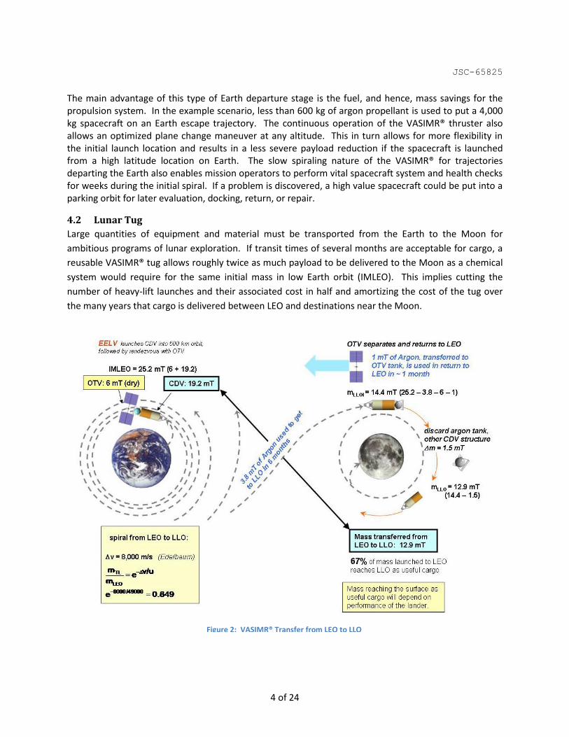
4.2 Lunar Tug
Large quantities of equipment and material must be transported from the Earth to the Moon for
ambitious programs of lunar exploration. If transit times of several months are acceptable for cargo, a
reusable VASIMR® tug allows roughly twice as much payload to be delivered to the Moon as a chemical
system would require for the same initial mass in low Earth orbit (IMLEO). This implies cutting the
number of heavy-lift launches and their associated cost in half and amortizing the cost of the tug over
the many years that cargo is delivered between LEO and destinations near the Moon.
Figure 2: VASIMR® Transfer from LEO to LLO

JSC-65825
5 of 24
The following mission assumptions were used for the simulation: input power provided by solar panel
cells P = 500 kW, VASIMR® power efficiency = 60 %, Isp = 5,000 sec, IMLEO = 25,200 kg (including both
OTV and CDV).
Figure 2 demonstrates a possible Lunar Tug architecture. It was assumed that an Evolved Expendable
Launch Vehicle (EELV) delivers a large Cargo Delivery Vehicle (CDV) into 500 km orbit, followed by
rendezvous with a VASIMR®-powered Orbital Transfer Vehicle (OTV) or “Tug”. The OTV transfers CDV
between a 500 km low Earth orbit (LEO) and a 100 km low lunar orbit (LLO) and returns to LEO. For low
thrust spiral trajectories without a plane change, the V is the difference between the initial and final
circular orbital velocities[10], which is 8 km/s for this mission, including both the spirals around the Earth
and the Moon. From the rocket equation, given in Figure 2, the VASIMR® could deliver the 14 mT
payload within 6 months, using 3.8 mT of propellant. For comparison, a chemical propulsion system
with specific impulse around 450 s can only deliver 5.7 mT payload for the same initial mass placed in
LEO.
Figure 3 shows the trajectory, calculated by the Copernicus code, in the Earth frame of reference. The
trip time is 178 days, the propellant used is 3,840 kg, and both numbers are very close to the estimates.
Figure 4 shows the same mission trajectory in the rotating Earth-Moon frame of reference, in order to
show both spiraling from LEO and de-spiraling to LLO. For this case, the inclination change was not
required. Copernicus uses four consecutive segments for the trajectory; each of them matched at their
connecting endpoints with respect to position, velocity, mass and time. The first and longest segment is
spiraling from LEO with the thrust vector directed along the velocity vector. The duration of the first
Figure 3: Copernicus Simulations of VASIMR® Transfer from LEO to LLO

JSC-65825
6 of 24
segment is one of the optimized variables and calculated to be 140 days and it requires 3,020 kg of
propellant. The end of the second segment is targeted to the point on the boundary of the Moon’s SOI
(relative to the Earth) closest to Earth. It lasts 3 days and requires 75 kg of propellant. Copernicus
optimizes the direction of the thrust vector in the second and third phases, as well as the transition
times between all phases. The third segment, capturing the payload in orbit around the Moon, lasts 5
days and requires 105 kg of propellant. A fourth, optional segment performs de-spiraling maneuver
with thrust directed opposed to the velocity in preparation for landing on the Moon by chemical means.
Copernicus calculates the fourth and third segments backward from LLO and connects the ends of the
second and third segments iteratively. This de-spiraling maneuver requires 30 days and 640 kg of
propellant.
Figure 4: Lunar Tug mission trajectory in the Earth-Moon Rotating Visualization frame

JSC-65825
7 of 24
Section 5. Robotic Missions Beyond Earth’s Sphere of Influence
5.1 Cargo Delivery to Mars
A parametric study of cargo delivery to Mars with 2 MW of power and a total specific mass of α = 4 kg/kW (power + VASIMR®) was performed using the OptiMars code with the variable Isp optimizer, for an IMLEO = 20 mT. The parameter varied was the minimum allowed specific impulse. The first segment of the mission is the spiraling from LEO with an initial altitude of 1,000 km to the Earth’s SOI. For Isp = 4,000 sec, the spiraling takes 27 days and requires 3.7 mT of propellant. Figure 5 demonstrates the 80 day heliocentric transfer from Earth to Mars orbit. The arrival speed was constrained to be 6 km/sec, assuming that aerocapture will be used for payload delivery to the Mars surface. The time varying profile for the specific impulse determined by optimization is shown in Figure 6. A maximum technology limit of 30,000 s was used for the specific impulse of the VASIMR® engine. The coasting time is about 10 days. For the optimized profile of the specific impulse with a minimum Isp of 4,200 sec, the heliocentric transfer requires 3 mT of propellant. So, from IMLEO = 20 mT, the total mass budget can be presented as 8 mT for power and propulsion plus 7 mT of propellant and 5 mT of payload. The total duration of the mission is about 3.5 months.
Figure 5: OptiMars Simulation of helio transfer from Earth SOI to Mars orbit

JSC-65825
8 of 24
The results of the parametric study are shown in the Figure 7 for the same IMLEO in all cases and varying minimum Isp. If the minimum Isp is increased from 4,200 sec to 6,200 sec, the total trip time goes up by 14 days but the amount propellant required goes down by 1.7 mT, so more payload can be delivered.
5.2 Mars Sample Return
The International Mars
Architecture for the Return of
Samples (iMARS) Working Group
has conducted extensive studies
on Mars Sample Return (MSR)
missions using chemical
propulsion technology [11]. In this
section, we investigate the use of
VASIMR® technology to
accomplish a MSR mission that is
a modified version of the one
proposed by the iMARS Working
Group.
This analysis is based on
reasonable values for the specific
mass for power levels in the range
between 100 and 500 kW. This
calculation was performed using
Chebytop assuming an initial mass
in LEO, IMLEO = 19,000 kg,
including 4,880 kg of payload fixed, leaving 14,120 kg for the OTV and propellant. Power received from
solar panel was assumed to depend on distance to the sun as ~1/R2. Figure 8 illustrates the various
stages of the mission:
1) An Atlas V 552 puts 19,000 kg into LEO at an altitude of 500 km. The spacecraft includes an OTV with
a VASIMR® thruster, a 4,000 kg Mars Lander (ML), and an 880 kg Earth Entry Vehicle (EEV). The masses
for ML and the EEV are taken from the MSR mission developed by the iMARS Working Group.
2) The spacecraft spirals up from LEO to the Earth’s SOI.
3) A heliocentric transfer to Mars is performed.
Figure 7: Changing Minimal Isp and Payload Mass as a function of Trip Time for Cargo Mission to Mars
Figure 6: Variable Isp profile for OptiMars heliocentric transfer simulation

JSC-65825
9 of 24
4) The 4,000 kg Lander is ejected just before the spacecraft begins its Mars orbit insertion. The Lander
follows a direct descent path, just as it would in the chemical mission.
5) The OTV spirals down to a low Martian Orbit (LMO) with an altitude of 500 km.
3. Heliocentric transfer to Mars
4. Lander separates to make direct landing
5. OTV spirals down to 500 km LMO
Earth SOI
925,000 km radius Mars SOI
577,000 km radius
2. OTV spirals up from LEO to
Earth’s SOI
1. Atlas V 552 puts 19,000 kg into 500 km LEO; OTV carrying 4000 kg Mars Lander and 880 kg
Earth Entry Vehicle
Figure 8: VASIMR® MSR Scenario: Earth to Mars
Figure 9 shows the 30 kg sample return with the following phases:
6-7) The sample container (30 kg) is returned to LMO, where it rendezvous with the OTV.
8) The combined package spirals up to reach the Mars SOI.
9) A heliocentric transfer returns the OTV and sample back to the Earth.
10-11) The 910 kg package, including the EEV to land the sample on the Earth is ejected from the OTV as
it begins its Earth Orbit Insertion, so that the sample container lands on the Earth and the OTV spirals
down to Low Earth Orbit.
Earth SOI Mars SOI 6. Mars Ascent Vehicle launches sample container to 500 km Mars orbit
7. OTV finds and captures sample container
8. OTV spirals up to Mars SOI
9. Heliocentric transfer to Earth
10. Earth Entry Vehicle separates from OTV for direct landing
11. OTV spirals down to LEO from Earth SOI
Figure 9: VASIMR® MSR Scenario: Mars to Earth
Figure 10 summarizes key results for this type of mission with different power levels.

JSC-65825
10 of 24
Figure 10: Power Scan for MSR Mission. For each power value, one-way trip times (and propellant mass) were minimized.
The power at 1 AU was varied between 100 kW and 500 kW. The one-way trip time was minimized for
each power level. The results of the parametric scan are demonstrated in Figure 10. The parametric
scan used the following values of input parameters:
Total power efficiency = 60 %
Specific impulse Isp = 5,000 sec,
IMLEO = 19,000 kg,
LEO altitude RLEO = 500 km,
Mars altitude RLMO = 500 km,
Minimal stay time on LMO is 4 months.
Lander Mass ML = 4 mT
Propellant Tank mass MPT = 0.1 MP
Initial mass for LMO–LEO segment = final mass of LEO–LMO segment – ML – MPT
In summary, a Mars sample return mission is possible at any power level between 100 kW and 500 kW
(at 1 AU). As Figure 10 shows, the roundtrip time decreases with increasing power with a substantial
decrease from 6.1 years at 200 kW to 3.7 years at 250 kW and a relatively slow decrease for power
levels between 250 kW and 500 kW (down to 3.1 years). The reason for the big decrease in trip time
just less than 250 kW is that the LMO stay time is not monotonic function of power. For low power
levels (100-200 kW) the LMO stay time increases from 0.4 year to 2.1 years, but for 250 kW of power,
the stay time can be reduced to 140 days due to the effect of the relative position of Earth and Mars.
The conclusion is that the optimal level of VASIMR® power for the MSR mission is 250 kW (at 1 AU),

JSC-65825
11 of 24
requiring a round trip time of 3.7 years, including 140 days in low Martian orbit. The mission can be
performed for specific total power, α < 21 kg / kW. Higher powers can make the mission slightly faster,
but require much more propellant and much lower α. For example, 500 kW mission can be
accomplished within 3.1 years but requires total α < 8 kg / kW. The optimal trajectory for 250 kW (at 1
AU) is shown in Figure 11 for the transfer from Earth to Mars and in Figure 12 for the return from Mars.
Thus, a 250 kW Mars Sample Return mission using a VASIMR® is able to accomplish the mission in 3.5
years, about the same as using chemical thruster technology, but requiring much less propellant
launched into LEO. Further optimization of the mission can be accomplished assuming variable specific
impulse and Copernicus simulations.
-2
-1.5
-1
-0.5
0
0.5
1
1.5
2
-2 -1.5 -1 -0.5 0 0.5 1 1.5 2
Mass balance [kg]: Mass at LEO 19000 Propellant (LEO-LMO) 5250 Tank 530 Lander (PL) 4000 _______________________ Mass at LMO 9220
Helio Transfer Departure: 1 June 2020
Helio Transfer Arrival: 27 Apr 2021
Accelerating: 147 days
Coasting: 31 days
Decelerating: 152 days
Power 250 kW (at 1 AU) stage Trip time Propellant Spiraling 227 days 2370 kg Heliotrans 330 days 2073 kg Despiral 203 days 812 kg Total 760 days 5250 kg Departure 18 Oct 2019 (LEO) Arrival 16 Nov 2021 (LMO)
Figure 11: From LEO to Mars: 250 kW

JSC-65825
12 of 24
-2
-1.5
-1
-0.5
0
0.5
1
1.5
2
-2 -1.5 -1 -0.5 0 0.5 1 1.5 2
Mass balance [kg]: Mass at LMO 9220 Propellant(LMO-LEO) 2740 Tank 280 EEV with Mars sample 910 _________________________ Mass at LEO 5390 Total Alpha 21
Decelerating: 122 days
Coasting: 87 days
Accelerating: 61 days
Helio Transfer Departure: 1 July 2022
Helio Transfer Arrival: 28 Mar 2023
Power 250 kW (at Earth orbit) stage Trip time Propellant Spiraling 87 days 493 kg Heliotrans 270 days 1361 kg Despiral 82 days 886 kg Total 439 days 2740 kg Departure 5 Apr 2022 (LMO) Arrival 18 Jun 2023 (LEO)
Figure 12: From Mars to LEO: 250 kW
5.3 Enhancing Solar Powered Capabilities to reach Jupiter
In this section, we explore the concept of a reusable VASIMR® spacecraft to “catapult” 5,000 kg robotic
payloads to Jupiter using a Hohmann-like transfer. The intent of this study is to identify the important
parameters for ejecting the payload and returning the VASIMR® system back to Earth for additional
payloads in reasonable periods of time. The operational parameters of interest are the power level,
propellant mass, payload release point, and distance of closest approach to the Sun to gain additional
solar power. Optimization based on variable specific impulse is needed to fully explore this concept.
However, two calculations at fixed specific impulse within the range of VASIMR® capabilities, one
assuming 5,000 s and another assuming 4,000 s, demonstrate the advantages of variable specific
impulse and indicate the direction for possible future studies.
The mission is based on the assumption that the catapult spacecraft and its payload begin at the Earth’s
sphere of influence (SOI), coasting in the Earth’s orbit about the Sun. The VASIMR® engine’s power
rating must match the peak power available when the spacecraft is closest to the Sun. The solar array is
assumed to be a planar array rather than a concentrator, to simplify its operation near the Sun where a
concentrator might otherwise overheat the photovoltaic cells.
The MESSENGER spacecraft[6] provides a starting point for estimating the mass of various sub-systems of
the VASIMR® Catapult which will make repeated flights from low Earth orbit to the inner solar system.
MESSENGER is expected to have a lifetime of approximately 10 years in this type of environment. The

JSC-65825
13 of 24
VASIMR® Catapult will have similar requirements for communications and Guidance, Navigation and
Control (GNC). The mass budget of the Catapult spacecraft is shown in Figure 13.
docking propulsion
(arcjet)
Argon mass depends on trajectory – expect several thousand kg
Assume 4,000 kg
launched to rendezvous and dock with
ejector in LEO
Argon propellant
& ZBO tank payload
ejector
solar array
VASIMR engines
avionics
thermal
communications
GNC
structure
harness
T = 5 kg/kW; thruster power = power at closest approach to Sun
A = 18 kg/kW; P = power @ 1 AU ; range 200 kW to 1 MW
100 kg
10% of sum of other components of the ejector (dominated by
VASIMR engines and solar array)
400 kg
30 kg
35 kg
100 kg
based on MESSENGER spacecraft total:
700 kg (this quantity is fixed)
35 kg
Figure 13: VASIMR® Catapult: Starting Point for Mass Relations
The mission trajectory was studied using the AdAstra3DTraj code and considered only the Sun’s
gravitational field. The mission begins with a deceleration phase from the Earth SOI with an initial mass
there (IMSOI) of 22 mT where the solar panels provide power, PEarth = 500 kW, with a propulsion
efficiency of the VASIMR® of = 60%. Two options for constant specific impulse were considered, one
with Isp = 4,000 s and another with Isp = 5,000 sec. Several iterations were performed to find out the
optimal distance for switching from deceleration to acceleration, and then a return of the Catapult
spacecraft to Earth’s SOI.
During the acceleration phase, the orbital elements of the vehicle’s trajectory are continuously
changing. In particular, the aphelion distance grows larger. As soon as the instantaneous aphelion
matches the semi-major axis of Jupiter’s orbit, the robotic payload should be released on an orbit that
will coast to Jupiter. After the payload is released, the Catapult’s thrust vector is then changed to begin
its rendezvous with Earth.
When the energy needed for ejection is reached, the payload with a mass of MPL= 4 mT and the empty
propellant tank with an assumed mass of MT = 0.1 MP is released from the VASIMR® Catapult. When the
payload is released, the Catapult immediately directs its thrust opposite to its velocity vector to
decelerate until the instantaneous aphelion distance is reduced to approximately 1 AU, thereby
initiating its rendezvous with the Earth for reuse.
JSC-65825
14 of 24
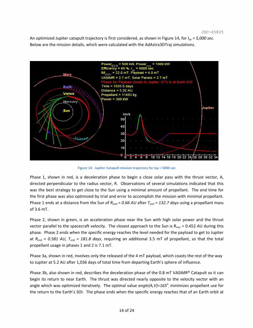
An optimized Jupiter catapult trajectory is first considered, as shown in Figure 14, for Isp = 5,000 sec.
Below are the mission details, which were calculated with the AdAstra3DTraj simulations.
Figure 14: Jupiter Catapult mission trajectory for Isp = 5000 sec
Phase 1, shown in red, is a deceleration phase to begin a close solar pass with the thrust vector, A,
directed perpendicular to the radius vector, R. Observations of several simulations indicated that this
was the best strategy to get close to the Sun using a minimal amount of propellant. The end time for
the first phase was also optimized by trial and error to accomplish the mission with minimal propellant.
Phase 1 ends at a distance from the Sun of Rend = 0.66 AU after Tend = 132.7 days using a propellant mass
of 3.6 mT.
Phase 2, shown in green, is an acceleration phase near the Sun with high solar power and the thrust
vector parallel to the spacecraft velocity. The closest approach to the Sun is Rmin = 0.452 AU during this
phase. Phase 2 ends when the specific energy reaches the level needed for the payload to get to Jupiter
at Rend = 0.581 AU, Tend = 181.8 days, requiring an additional 3.5 mT of propellant, so that the total
propellant usage in phases 1 and 2 is 7.1 mT.
Phase 3a, shown in red, involves only the released of the 4 mT payload, which coasts the rest of the way
to Jupiter at 5.2 AU after 1,036 days of total time from departing Earth’s sphere of influence.
Phase 3b, also shown in red, describes the deceleration phase of the 0.8 mT VASIMR® Catapult so it can
begin its return to near Earth. The thrust was directed nearly opposite to the velocity vector with an
angle which was optimized iteratively. The optimal value angle(A,V)=165o, minimizes propellant use for
the return to the Earth’s SOI. The phase ends when the specific energy reaches that of an Earth orbit at

JSC-65825
15 of 24
distance R = 1.179 AU, after 231.4 days, using an additional 1.5 mT of propellant. The remaining phases
are then performed with thrust directed orthogonally to velocity, so the specific energy does not
change.
Phase 3c, shown in light blue, is a maneuver to return the catapult to the Earth with the thrust vector, A,
orthogonal to the velocity vector, V, and toward the Sun, ending at 1.452AU, after a total of 279.2 days
using an additional 0.6 mT or propellant.
Phase 3d, shown in gray, is a simple coasting phase to 1.478 AU after a total of 359.2 days.
Phase 3e, shown in magenta, is a maneuver turning away from the Sun with thrust vector, A, orthogonal
to the velocity vector, V, opposite the Sun to rendezvous at 1 AU after a total 509.5 days, using an
additional 2.4 mT of propellant. The cumulative propellant usage is 11.5 mT.
To illustrate the effect of specific impulse on the technology requirements for the specific mass, the
catapult mission was repeated for a lower specific impulse with Isp = 4000 s using the same maneuvers.
The results from the AdAstra3DTraj simulations at 4000 s are:
Phase 1 ends at Rend = 0.9 AU, after 80.7 days, using 2.9 mT of propellant.
Phase 2 ends at Rend = 0.729 AU, with a closest approach to the Sun at 0.657 AU, after a total of 157.4
days, using an additional 4.6 mT of propellant.
Phase 3a delivers the payload to Rend = 5.2 AU, after a total of 1,057 days.
Phase 3b with angle(A,V)=150o ends at Rend = 1.156 AU, after a total of 210.8 days, using 2.1 mT of
propellant.
Phase 3c ends at Rend = 1.27AU, after 240.3 days, using 0.7 mT of propellant.
Phase 3d coasts to an ending radius at Rend = 1.121 AU, after 363.3 days.
Phase 3e ends at Rend = 1 AU, after a total of 406.8 days, requiring an additional 1.3 mT of propellant,
such that the entire mission uses 11.6 mT of propellant.
One advantage of lowering the specific impulse from 5,000 s to 4,000 s is a relaxation in technology
requirements from α = 6.8 kg/kW for 5,000 seconds to α = 8.4 kg/kW for 4,000 seconds. However, the
efficiency of the VASIMR® system may be more challenging for lower specific impulse. In addition, the
mass of the propellant to return to Earth is significant, so missions without a return to earth can have
larger, or multiple payloads, offering options for future study.
The primary result from these two studies at different fixed specific impulse is that the initial phases,
needed to release the payload on its way to Jupiter, can be performed with 7.1 mT using 5,000 s, but
require 7.5 mT at 4,000s. Alternatively, the return of the catapult spacecraft to the Earth for future
reuse can be performed with 4.1 mT of propellant using a specific impulse of 4,000 s whereas the return

JSC-65825
16 of 24
phases require 4.5 mT using a specific impulse of 5,000 s. Clearly, varying the specific impulse between
the out-bound and return maneuvers can result is significant savings, warranting further study.
Section 6. Fast Human Missions to Mars with Variable Specific Impulse
In this section we assume that very high power sources are available, such as might be possible with
advanced nuclear power technology. With ample power for interplanetary missions, the VASIMR® can
significantly reduce launch mass and trip times compared with chemical thruster technology. At the
200 mega-Watt power level, human missions to Mars in less than 39 days become conceivable with
advanced VASIMR® and power technologies. Trip times to Mars on this time scale were mentioned as a
laudable goal for NASA by its administrator, Charles Bolden[9], in July 2009, because they dramatically
improve a crew’s survivability and safety in the interplanetary space environment. In this section, we
present conceptual studies showing the dependence of the trip time on the initial departure position,
initial mass at the departure position, mass of the payload, variable specific impulse, and the mass-to-
power ratio for the power and propulsion systems. The return mission is not presented in this report.
6.1 Human Mission to Mars using 12 MW
The variable specific impulse made possible by VASIMR® technologies can be fully appreciated for multi-
megawatt interplanetary missions. These studies were conducted using the HOT[7], [8] software package
and demonstrate the possibility of 12-18 MW missions arriving at Mars within 3-4 months, about half
the time estimated in the Design Reference Mission (DRM) 3.0[12], which utilizes Nuclear Thermal
Rockets for transferring to Mars. The mission analysis assumed the exact same payload mass delivered
to the atmosphere of Mars (60.8 mT) at the same velocity for aerocapture (6.8 km/s) as in the DRM 3.0
for the crewed portion mission with VASIMR® engines. The crew time in space could be reduced by
about one month by rendezvousing the crew with the VASIMR®-powered spacecraft in high earth orbit
after the main vehicle had passed through the Van Allen belts.
For this mission cargo must be pre-deployed both in Martian orbit and on the surface. In the DRM, one
rocket transfers the cargo lander and another transfers an earth return vehicle with a living habitat for
the crew to Mars. The total mass of those payloads is 91.4 mT as outlined in the DRM 3.0 (including an
aeroshell for the cargo lander sized appropriately for entry velocity). The VASIMR® mission proposes
combining both payloads plus the return propellant on one vehicle to save propellant on the outbound
journey. A VASIMR® system with one third the power, 4 MW, compared to the 12 MW of the crewed
vehicle, transfers the payload more slowly, requiring a 154 day spiral plus a 288 day heliocentric
transfer, but uses one third less initial mass with an IMLEO of 202 mT, compared with 282 mT for the
DRM. The return habit is stored in orbit at Mars, as in the DRM 3.0, waiting for the Mars ascent vehicle
and the crew for the return trip.
The crewed spacecraft departs LEO on May 6, 2018. The ship initial mass in LEO is 188 mT. 12 MW of
electric power is assumed for the duration of the trip with a total mass-to-power ratio of =4 kg/kW,
which includes the nuclear power supply, VASIMR®, and all other vehicle mass except propellant and

JSC-65825
17 of 24
propellant tanks. Therefore, the Crew Transfer Vehicle (CTV) mass is 48 mT plus the propellant and
propellant tank mass. The mass breakdown for the 60.8 mT Mars Lander (ML) is assumed to be 31.0 mT
for the habitat, 13.5 mT for an aero-shell, and 16.3 mT for a descent system. The CTV, mated to the ML
(Mars Lander), will transport the crew to Mars. The speed relative to the Earth is 2.5 km/s at the Earth’s
gravitational sphere of influence. Figure 15 shows the piloted mission trajectory and Isp profile.
The ML will separate from the CTV at Mars arrival. The lander is designed to approach Mars with a
relative velocity of 6.8 km/s and execute a direct descent to the surface. The Lander descent maneuver
is identical to that outlined in the DRM. The CTV will initially execute a flyby of Mars, close enough to
drop off the ML. The CTV will continue past Mars in an arcing trajectory to be captured by the planet
approximately four months later. The approach to Mars and the elliptical spiral to low Martian orbit
(LMO) are shown in Figure 16.
Figure 15: Human piloted heliocentric transfer with Isp vs time plot (right)
The separation of the ML from the propulsion system at Mars arrival and its direct entry are
operationally reasonable based on the Design Reference Mission. The delay in achieving orbital insertion
of the interplanetary propulsion module at Mars, results in considerable fuel and time savings. While
some risk is involved in this approach, the crew has a possible backup because the Cargo Vehicle in LMO
contains the Earth Return Vehicle and the return propellant, as well as a fully functional, albeit lower
power, VASIMR® module. This configuration could be used in a contingency, should the prime
propulsion system fail to achieve LMO. Such an option will result in a longer return trip time.
JSC-65825
18 of 24
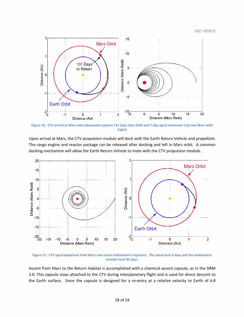
Figure 16: CTV arrival at Mars and subsequent capture 131 days later (left) and 7-day spiral maneuver into low Mars orbit (right)
Upon arrival at Mars, the CTV propulsion module will dock with the Earth Return Vehicle and propellant.
The cargo engine and reactor package can be released after docking and left in Mars orbit. A common
docking mechanism will allow the Earth Return Vehicle to mate with the CTV propulsion module.
Figure 17: CTV spiral departure from Mars and return heliocentric trajectory. The spiral lasts 4 days and the heliocentric transfer lasts 85 days.
Ascent from Mars to the Return Habitat is accomplished with a chemical ascent capsule, as in the DRM
3.0. This capsule stays attached to the CTV during interplanetary flight and is used for direct descent to
the Earth surface. Since the capsule is designed for a re-entry at a relative velocity to Earth of 6.8

JSC-65825
19 of 24
km/sec, the vehicle is targeted to approach Earth with that velocity. The return mission follows a similar
strategy. It consists of a 4 day Mars spiral followed by an 85 day heliocentric transfer, as shown in Figure
17.
6.2 Human Mission Scenarios to Mars using 200 MW
6.2.1 Technology Requirement Estimates from OptiMars
A 200 MW human mission to Mars was evaluated using the OptiMars program assuming an initial mass
at LEO of 600 mT, with initial altitude of 1,000 km, a VASIMR® efficiency of 60%, and a specific impulse
of 3,200 sec. For this power level, the spiraling from LEO to Earth’s SOI requires 8 days, and 165 mT of
propellant. This spiral saves a significant amount of propellant over a chemical maneuver to near the
Earth’s SOI, however, a chemical rendezvous near Earth’s SOI between astronauts and the VASIMR®
spacecraft could be considered to reduce the crew’s exposure to the Van Allen belts, further reduce trip
time, and also to relax the minimum specific impulse requirements for the VASIMR® technology. No
chemical-based rendezvous is considered here, but future study may be useful.
In this evaluation, propellant usage during the second stage heliocentric transfer is optimized by
escaping the Earth with a velocity directed away from the Sun with zero tangential velocity relative to
Earth at a speed of 5.5 km/s. The mass and velocity at the end of this spiral maneuver is used to
initialize the second stage heliocentric transfer between Earth and Mars, as shown in Figure 18. The
optimal 31-day heliocentric transfer requires 295 mT of propellant with variable specific impulse
following the profile shown in Figure 19 between 3,000 s and 30,000 sec. A 3-day period in the middle
of the heliocentric transfer had the VASIMR® thrusters running at maximum specific impulse prior to the
slowing of the craft in preparation for orbital capture by Mars. The arrival velocity at the end of the
heliocentric transfer is 6.8 km/sec, which requires aerocapture to slow the lander for capture. The
arrival mass to Mars for this scenario is 140 mT, and the mass of the payload is somewhat arbitrarily
picked to be 20 mT, the mass budget for the power systems and VASIMR® thrusters is 120 mT, requiring
a total alpha of less than 0.6 kg/kW. Current technologies cannot achieve specific mass values this low,
although some theoretical studies predict power plant specific masses below 1 kg/kW. Thus, pre-
positioning of cargo and crew-support facilities in Martian orbit may be required to achieve the shortest
times for crewed missions. Nevertheless, the orbital mechanics identified by the OptiMars program
warrants a more thorough evaluation of missions to identify the technology needed, as measured by
specific mass, using Copernicus.

JSC-65825
20 of 24
Figure 18: OptiMars simulation of 31-day heliocentric transfer from Earth to Mars. The maximum speed relative to the sun is roughly 40 km/s prior to the slowing maneuver to transfer into the orbit of Mars.
Figure 19: Profile of variable specific impulse for 31-day heliocentric transfer between Earth and Mars orbits – second stage of a very fast human mission to Mars. The horizontal axis indicates the relative heliocentric transfer trip time starting with departure from the Earth SOI and ending with arrival to the Mars SOI

JSC-65825
21 of 24
6.2.2 Optimized Results from Copernicus
The effects on trip time and payload for 200 MW human scenarios caused by varying the technology
requirements, measured by total specific mass and arrival velocity, are presented in this section. Figure
20 demonstrates an optimized 31-day heliocentric transfer for the mission to Mars using the Copernicus
program. The optimal departure date from Earth SOI in the next 20 years was calculated to be July 15,
2018. The corresponding optimized variable specific impulse profile is shown in Figure 21. The final
mass after the heliocentric transfer is 145 mT, in good agreement with, and slightly higher than
estimated by OptiMars. In this study, we relax the total specific mass requirements by parametrically
varying the arrival speed at Mars SOI and the mission time while keeping the initial mass at Earth’s SOI
and the final payload mass at Mars fixed. Additional improvements beyond the scope of this study can
likely be obtained by chemical rendezvous of a human crew with pre-positioned resources at libration
points of the Earth-Moon system.
Figure 20: Copernicus simulation of 31-day heliocentric transfer from the Earth’s SOI to Mars. The yellow lines indicate thrust vectors.

JSC-65825
22 of 24
0
3000
6000
9000
12000
15000
18000
21000
24000
27000
30000
33000
0 5 10 15 20 25 30
time [days]
Isp
[sec]
Isp [sec]
Figure 21: Copernicus simulation of variable specific impulse profile for 31-day heliocentric transfer from Earth SOI to Mars
Figure 22 shows the required total specific mass, α, for different mission times and arrival velocities.
These results show that heliocentric transfer times for delivering a fixed 20 mT payload from L1 to Mars
using a fixed initial mass at Earth’s gravitational sphere of influence of 600 mT, can be in the range of 55
to 60 days depending on the arrival velocity at Mars with a total propulsion α of approximately 2 kg/kW.
A 39-day mission to Mars with an arrival velocity 10 km/s can be achieved with total specific mass of 1.2
kg/kW. Achieving trip times of less than 90 days for these mass transfers requires the total propulsion
technology, measured by α, to be less than about 2.5 kg/kW. Note that slow missions don’t need such
high power levels. For example, 90 day mission to Mars can be accomplished with power levels close to
12 MW as reported in previous section. Additional mass staging for departure near L1 with 800 mT may
further relax the technology requirements on the propulsion system to α around 4 kg/kW, but further
study is required.
0.00
0.50
1.00
1.50
2.00
2.50
3.00
35 45 55 65 75 85
Trip time [days]
To
tal
alp
ha
[k
g/k
W]
V_arr=0km/s
V_arr=2km/s
V_arr=4km/s
V_arr=6km/s
V_arr=8km/s
V_arr=10km/s
Figure 22: Parametric study of human mission to Mars trip time departing from L1 with minimal Isp = 3,000 sec, IML1 = 600
mT, P = 200 MW, = 60%, MPL = 20 mT.

JSC-65825
23 of 24
Section 7. Summary and Future Work
A survey of space exploration missions enabled by VASIMR® technologies has been preformed using a wide range of simulation tools including near-Earth, deep-space robotic and human missions. This survey provides a map to guide more specific and detailed analysis of scenarios enabled by exploiting and developing VASIMR® technologies. It also provides guidance for evaluating the trade-offs, risks, and rewards inherent in developing new technologies. A 500 kW Lunar Tug scenario based on a VASIMR® driven spacecraft and existing state-of-the-art solar cell technology with a total propulsion alpha of 10 kg/kW, is able to achieve significant mass savings over all chemical thruster technology. For an IMLEO of 25.2 mT, the VASIMR® tug can deliver 14 mT of payload to low lunar orbit (LLO) versus 5.7 mT delivered by traditional chemical means. Thus, the cost to pre-position cargo and equipment near the Moon can be cut in half using technologies that are available in the near term. Similarly, a 250 kW Mars Sample Return mission using a VASIMR® is able to accomplish the mission in 3.5 years, about the same as using chemical thruster technology, but requiring much less propellant launched into LEO. The major advantage of Variable Specific Impulse technology is demonstrated for high power deep-space robotic missions. A scenario based on presently available solar power technologies with 500 kW of power and alpha of 6.4 kg/kW can launch 4 mT of payload beyond the orbit of Jupiter. Besides using much less propellant than chemically powered missions, the VASIMR® Catapult to Jupiter optionally has the advantage of reusing the hardware to amortize the initial investment. This technique warrants further study to better identify its capabilities, trade-offs, and advantages. Perhaps the most laudable goals for the technology are that it should eventually enable human missions to Mars that are much faster and safer than can be achieved with chemical rockets. Trips to other near-Earth objects clearly warrant similar studies. Using 12 MW of power and a total specific mass for the entire power and propulsion system of a challenging, but presently realizable 4 kg/kW, allows a scenario with a crewed one-way mission time of approximately 3 months. Assuming advanced technologies that reduce the total specific mass to less than 2 kg/kW, trip times of less than 60 days will be possible with 200 MW of electrical power. One-way trips to Mars lasting less than 39 days are even conceivable using 200 MW of power if technological advances allow the specific mass to be reduced to near or below 1 kg/kW.
Section 8. References [1] Ocampo, C. “An Architecture for a Generalized Trajectory Design and Optimization System”,
Proceedings of the International Conference on Libration Points and Missions, Girona, Spain June
2002
[2] Hahn, D. W., Johnson, F.T., and Itzen, B. F., “Final Report for CHEBYCHEV Optimization Program
(CHEBYTOP),” The Boeing Company Report No. D2-121308-1, NASA-CR-73359 (or 69N34537), July
1969

JSC-65825
24 of 24
[3] Yam, C. H. and Longuski, J., M., “Optimization of Low-Thrust Gravity-Assist Trajectories with a
Reduced Parameterization of the Thrust Vector,” AAS/AIAA Astrodynamics Specialist Conference
and Exhibit, AAS Paper 05-375, 1995, Lake Tahoe, CA
[4] K. Karavasilis, “Earth-Mars Trajectory Calculations”, 4-th VASIMR Workshop, Houston, TX, March 28,
2001.
[5] BBC News (2007). Concern over China's missile test. Retrieved January 20, 2007.
"Satellites Collide, Put Space Station at Risk". The Washington Post. February 11, 2009.
http://www.washingtonpost.com/wp-dyn/content/article/2009/02/11/AR2009021103387.html
[6] Messenger facts on web: http://www.astronautix.com/craft/mesenger.htm or
http://en.wikipedia.org/wiki/MESSENGER
[7] Chang Díaz F. R., Braden E., Johnson I., Hsu M. M., Yang T. F. (1995) Rapid Mars Transits With
Exhaust-Modulated Plasma Propulsion, NASA Technical Paper 3539, 10p
[8] Chang Díaz F. R. (2000) The VASIMR Rocket, Scientific American, November 2000, 283 (5) 90-97.
[9] Grossman, L. (2009) Ion engine could one day power 39-day trips to Mars, New Scientist, 22 July
2009.
[10] Edelbaum, T. N. (1964) “Propulsion Requirements for Controllable Satellites”, ARS Journal, 31: 1079-
1089. August 1961.
[11] “Preliminary Planning for an International Mars Sample Return Mission”, Report of the International
Mars Architecture for the Return of Samples (iMARS) Working Group, June 1, 2008.
[12] “Human Exploration of Mars: The Reference Mission of the NASA Mars Exploration Study Team”,
Hoffman, S. J., Kaplan, D. I. NASA/SP—6107–ADD, NASA-JSC, 60 p., 1998.