a study of ship hull crackarrester · pdf filei-, ssc-265 a study of ship hull crackarrester...
TRANSCRIPT

i-,
SSC-265
A STUDY OF
SHIP HULL CRACKARRESTER SYSTEMS
This document has been approvedfor public release and sale; its
distribution is unlimited.
SHIP STRUCTURE COMMITTEE1971
A: --— .—..-—.——. ._ _._. . . —

MEMBER AGENCIES:
United SIoIes CoosI Guard
Naval Seo Systems Command
MI II ICIry Sealifl Command
Montime Administration
American Bureau of Shipping
SHIP STRUCTURE COMMIHEEAN INTERAGENCYADVISORY
COMMITTEEDEDICATEDTO IMPROVINGTHE STRUCTUREOF SHIPS
ADDRESS CORRESPONDENCE TO
Secretary
Ship Structure Committee
U.S. Coast Gunrd Headquarters
Washington, D.C. 20590
SR-226
The development of new materials and the increased sophis–
tication of computer assisted stress–analysis techniques provided
an opportunity for the Ship Structure Committee to review and evaluate
current and proposed ship hull crack arresting systems. Major emphasis
was put upon dynamic fracture mechanics for the proper classification
and evaluation of the crack arrester systems investigated. Results
have also been compared with a static arrest toughness analysis.
The results contained in this report indicate that 1) there
is no general type of crack arrest system completely superior to all
others in all circumstances; 2) an exact quantitative evaluation must
be performed for each application; and 3) insufficient fundamental
work has been done to provide a fully rational or scientific approach
for crack arrester design. A five element research program has been
proposed to remedy these deficiencies. This will be considered by
the Ship Structure Committee in the future.
W. M. Benkert
Rear Admiral, U.S. Coast Guard
Chairman, Ship Structure Committee

FINAL TECHNICAL REPORT
on
Project SR-226
“Hull Crack Arrester Systems”
A STUDY OF SHIP HULL CRACK ARRESTER SYSTEMS
by
M. KanninenE. MillsG. HahnC. Marschal”D. BroekA. CoyleK, Masubush-K. Itoga*
*
BATTELLE COLUMBUS LABORATORIES
under
Department of the NavyNaval Sea Systems Command
Contract No. NOO024-75-C-4325
*MIT, Consultants to BATTELLE
This document has hen app~oved for public releaseand sale: its distribution is unlimited.
U. S. Coast Guard HeadquartersWashington, D.C.
1976
.ABSTFUCT
A world-wideagencies was conductedto arresting cracks in
survey of marine engineers, shipyards, and regulatingto ascertain both current and contemplated approachesship hulls. As a result of this survey, a crack ar-
rester classification system was developed. The clasS.lfication was used to aidin a systematic investigation aimed at determining the most attractive practicalschemes for arresting cracks in ship hulls. In additionto describing the classi-fication system, example calculations showing quantitatively the effect of imposingvarious kinds of mechanical arrester devices in the path of a fa”st7moving crackare given in the report. Considerable background material on the theoretical con-cepts and material characterizations required for the arrest of fast.fracturesand fatigue is also given. Taken together the work described in the report canbe used as a first step in developing guidelines for ship designers in situationswhere structural perturbationspropagation are envisioned.
for the purpose of arresting unstable crack
-,
-ii-

,/’
—.—.- ---- --------
1.0 INTRODIJCTION . . . . .
‘TABLE(II!LUN”l’JiN”IS
. . . . . . . . . . . . . . . . . .
2.0 DESCRIPTION OF EXISTING CRACK ARRESTER DESIGN PWCTICES. .
2.1 Basic Principles and Classification of Arresters. . .
2.2 Ship Classification Society Rules . . . . . . . . . .
2.3 Survey of Marine Engineers, Shipyards, and RegulatingAgencies.
2.3.1 Results of Domestic Survey . . . . . . . . . .
2.3.2 Results of Foreign Survey. . . . . . . . . . .
3.0 CONCEPTS FOR ARREST OF FAST FIWCTURE . . . . . . . . . . .
3.1
3.2
3.3
3.4
3.5
3.6
Analysis of Fracture Arrest . . . . . . . . . . . . .
Crack Arrest Material Properties. . . . . . . . . . .
The Static Arrest Toughness (&a, Ka) Analysis . . . .
Applications of the Static Toughness Arrest Approach,as Used in Japan.
Fracture Arrest Approach as Used In Aircraft ● . . -Structures.
Dynamic Analysis of Crack Propagation and Crack . “ .Arrest.
3.6.1 Governing Equation for Dynamic Crack . . - . ~Propagation in the DCB Test Specimen .
3.6.2 General Approaches to Crack Propagation and .Crack Arrest .
3.6.3 Comparison of Crack Arrest Predictions . . . .
4.0 FATIGUE.CRACK PROPAGATION. . . . . . . . . . . . . . . . .
4,1 Introduction. . . . . . . . . ... . . . . . . . . . .
4.2 Concepts of Crack Growth Analysis . . . . . . . . . .
4.3 Stress History Effects. . . . . . . . . . . . . . . .
4.4 Analysis of Service Cracks. . . . . . . . . . . . . .-iii-
233.5
1
3
3
7
12
12
13
17
17
23
26
29
29
33
37
42
46
52
52
52
53
55

-.L-
TABLE OF CONTENTS (Continued)
5.0
6.0
7.0
8.0
4.5 Fail-Safe Concepts.. . . . . . . . . . . . . . . . .
4.6 Crack Arresters and Fatigue . . . . . . . . . . . . .
CHARACTERIZATION OF ARRESTER MATERIALS . . . . . . . . . .
5.1 Estimate of ~(or Kc) for Arrester Materials. . . .
5.2 Measuring ~ Values of Tough Arrester Steels. . . . .
5.2.1 Approximating ~ Values With K KIC, or .JIC ,Measurements . c’
5.2.2 Approximating ~ From Crack-Opening Dis- . . .placement.
5.2.3 Direct Measurement of KTD or ~ With BartelleDuplex DCB Test.
5.3 Correlation of LEFM.Parameters with DTE Measurements.
5.4 Rolfe’s Proposed Requirements for Arrester Toughness.
5.5 Data for Ship Steels. . . . . . . . . . . . . . . . .
5.6 Implications for Arrester Design. . . . . . . . . . .
CRITICAL COPD?ARISON OF CURRENT AND PROPOSED.CRACK ARRESTERCONCEPTS .
RECOMMENDATIONS FOR FUTURE RESEARCH. . . . . . . . . . . .
REFERENCES. . . . . . . . . . . . . . . . . . . . . . . ,
APPENDIX A
DERIVATION OF FRACTURE ENERGY, TOUGHNESS AND WIDTH REQUIREMENTSFOR IN-PLANE ENERGY ABSORBING ARRESTER MODEL , . . . . . . . .
~
56
58
63
63
67
67
68
69
71
72
75
76
77
85
89
95
-iv-

/’
Figure 2.2.1 Riveted Seam Type of Crack Arrester . . . . . . . . . . 4
Figure 2.2.2 Inserted Type of Crack Arrester . . . . . . . . . . . . 4
Figure 2.2.3 Patch Type Crack Arrester . . . . . . . . . . . . - . . 5
Figure 2.2.4 Stiffener Type Crack Arresters . . . . . . . . . . . . 6
Figure 2.2.5 Ditch Type Crack Arrester . . . . . . . . . . . . . . . 6
Figure 2.3.1 Simplified Tanker Midship Section . . . - - - “ “ . . - ~~showing Basic Steel.Requirements .
Figure 2.4.1 Bilge Keel Crack Arrester Design (Eriksbergs) . . . . . 14
Figure 3.1.1 Schematic Representation of the Components - . . - “ . 19of the Crack Driving Force, G, the FractureResistance R and Crack Velocity V Attendingthe Fracture of a Structural Member UnderFixed Grip Conditions .
Figure 3.1.2 IFfluence of Loading System Compliance and . . . . . . 20Mass on Crack Propagation and Arrest in the(Zero Taper) Rectangular-DCB (ao/h = 1.0) Test“Piece for Type A Material Response and
%/KIl) mi~ = 1.5 .
Figure 3.1.3 Examples of the Principal Strategies for “ . . . . . . 22Promoting Crack Arrest .
Figure 3.2.1 Examples of the Crack Velocity Dependence . . . . . . . 24of the Fracture Resistance R and the CorrespondingPropagating Crack Toughness KD .
Figure 3.2.2 Comparison of K1d Measurements of Shabbits with KIa- “ . 27Measurements by Crosley and Ripling, Both onA533B Steel .
Figure 3.3.1 Influence of the Crack Jump Distance on the . . . . . . 27Arrest Toughness, K1a, of A533B Steel After
Crosley and Ripling .
Figure 3.3.2 Comparison of Experimental Results for Stiffener- . . . 28Types of Crack Arresters with Predictions From theStatic Analysis after Yoshlki, et al.
Figure 3.4.1 Comparisons of Experimental Results for Large, . . . . . 31Welded-Type, Energy Absorbing Crack ArresterModels with Calculations Based on the StaticAnalysis after Kihara, et al.
-v-
.— “.

Figure 3.5.1
Figure 3.5.2
Figure 3.5.3
“Figure3.5.4
Figure 3.6.1
Figure 3.6.2
Figure 3.6.3a
Figure 3.6.3b
Figure 3.6.4
Figure 3.6.5
Figure 3.6.6
Figure 3.6.7
Figure 4.3.1
Figure 4.5.1
Figure 4.5.2
Figure 4.5.3
Figure 4.5.4
LIST OF FIGURES (Continued)
X22fiE
Analysis of Stiffened Panel . . . . . . . . . . . . . . 34
Skin Stress Reduction and Stringer . . . . . . . . . . 34Load Concentration.
,.
Arrest Diagram for Stringer Critical Case , i . . . . . 35
Arrest Data by Vlieger for Aluminum Alloy . . . . . . . 35Panels with Z-Stiffeners.
Graphical Illustration of Dynamic Crack Propagation . . 43Criterion for Speed-Dependent Materials .
DCB Specimen Geometry for Arrester Calculations . . . . 48
Crack propagation Computations for a DCB . . . . . . 48Specimen with an Intermittently AttachedStiffener Crack Arrester for Kq/KIC = 2.0 .
Comparison of Crack propagation Predictions . . . . . 48From Fully Dynamic Analysis With Quasi-DynamicAnalysis for a Standard DCB Specimen with KD = KIC .
Comparison of Crack Arrest Point in a DCB Test . . . . 50Specimen with Static and with Fully Dynamic Analysis
Distribution of Energy During Rapid Crack Propagation . 50in a DCB Test Specimen for Kq/K1c = 2.0 and KD = KIC.
Crack Speeds in the DCB Test specimen Calculated. . . . 51By a Fully Dynamic Analysis as a Function of theStress Intensity at Initiation of Growth.
Calculated Crack Arrest Point in DCB Specimens . . . . 51with High-Toughness Arrester Using a Static Analysis.
Retardation of Fatigue Crack Growth. . . . . . . . . . 54Due to overloads .
Crack Growth and Fail-Safety . . . . . . . . . . . . . 57
Stress Exceedance Spectra for Two Ships, . . . . . . . 59Each for 20 Years Experience .
Assumed Crack Rate Properties for Crack- . . . . . . . 59Growth Curves in Figure 4.5.2 .
Hypothetical Crack Growth Curvesin the Basis of Two Ship Spectra
-vi-
Calculated . . . . . . 59.

LIST OF FIGURES (Continued)
Figure 4.6.1
Figure 4.6.2
Figure 5.1.1
Figure 5.1.2
Figure 5.2.1
Figure 5.2.2
Figure 5.3.1
Figure 6.1.1
Figure 6.1.2a
Figure 6.1.2b
Figure 6.1.3a
Figure 6.1.3b
Figure 6.1.4a
Figure 6.1.4b
Figure 7.1.1
Figure A-1.
Fatigue Crack Growth in Stiffened . . . . . . . . .Panel According to Poe.
Fatigue Crack Propagation in Integrally . . . . . .Stfffened Panel According to Poe.
Schematic Representation of a Large, Uniformly . . .Stressed Plate With TWO Welded-In, In-Plane, CrackArresters of the Same Thickness as the Base Plate.
Estimated Minimum KD Requirements for Arrester . . .Steels Based on Equation (5.3).
DCB-Test Piece Configuration; Side Grooves . . . . .Are Not Shown.
Relation Between Crack Velocity and Dynamic . . . .
Toughness for Steels Tested Near NDT.
Calculated and Observed Relationships Between . . .Dyriamic,Tear Energy and Fracture Toughness.
Crack Arrester Systems Tested . . . . . . . . . . .With the DCB Specimen.
Crack Propagation Computations for a DCB . . . . . .Specimen With a High-Toughness ArresterSection Using a Dynamic Analysis.
&
61
61.
64,.
66,.
70. .
70. .
73. .
80. .
80. .
Calculated Crack Arrest Point in a DC13i. . . . . . . . . 80.Specimen with a High-Toughness ArresterSection Using a Dynamic Analysis.
Comparison of Crack Arrest Points Predicted by . . . . . 82a Fully Dynamic Analysis with That of a Quasi-Dynamic Analysis for a SCandard DCB Specimenwith KD = KIC .
Calculated Crack Arrest point in”a DCB Specimen . . . . 82with an Intermittently-Attached Stiffener CrackArrester as a Function”of the Stiffener Thickness .
Crack Propagation Computations for a DCB Specimen . . . .82with a Constant-Tension Crack Arrester Devicefor Kq/K1c = 2.0 .
Calculated Crack Arrest Point in a DCB Specimen . . . . 82with a Constant-Tension Crack Arrester Device asa Function of the Force Applied to the Specimen .
Reinforced Ship Hull. . . “ . . . . . “ . . . . . . . . 88
Variation of the EnergY Te~~ . . . . . . . . . . . . . 96
-vif-
...—
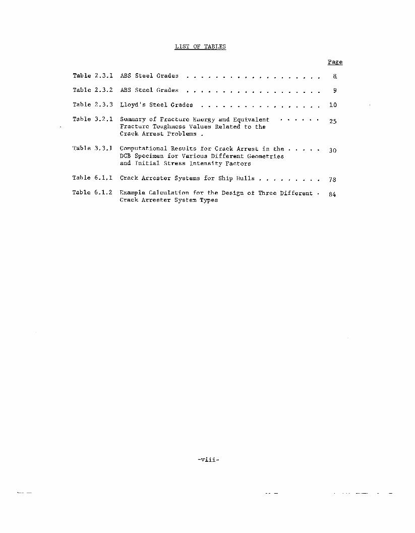
LIST OF TABLES
Table 2.3.1 ABS Steel Grades . . . . . . . . . . . . . . ... ..8.
Table 2.3.2 ABS Steel Grades . . . . . . . . . . . . . . ... ,.9
Table 2.3.3 Lloyd’s Steel Grades . . . . . . . . . . , . , . . , . 10
Table 3.2.1 Summary of Fracture Energy and Equivalent . . . . . . 25Fracture Toughness Values Related to theCrack Arrest problems .
Table 3.3.1 Computational Results for Crack Arrest in the . . . . . 30DCB Specimen for Various Different Geometriesand Initial Stress Intensity Factors
Table 6.1.1 Crack Arrester Systems for Ship HU1lS . . . . . . . . . 7g
Table 6.1.2 Example Calculation for the Design of Three Different . 84Crack Arrester System Types
-— —
-viii.
— —

SHIP STRUCTURE COMMITTEE
The SHIP STRUCTURE COMMITTEE is constituted to prosecute a researchprogram to improve the hull structures of ships by an extension of knowledgepertaining to design, materials and methods of fabrication.
RADM W. M. Benkert, USCGChief, Office of Merchant Marine Safety
U.S. Coast Guard Headquarters
Mr. P. M. Palermo Mr. M. PitkinAsst. for Structures Asst. Pidministrator forNaval Ship Engineering Center Commercial DevelopmentNaval Ship Systems Command Maritime Administration
Mr. J. L. Foley Mr. C. J. WhitestoneVice President Maintenance & Repair OfficerAmerican Bureau of Shipping Military Sealift Command
SHIP STRUCTURE SUBCOMMITTEE
The SHIP STRUCTURE SUBCOMMITTEE acts for the Ship Structure Committeeon technical matters bv ~rovidinq technical coordination for the determination
“,
of goals and objectives of the program,results in terms of ship structural ales”
NAVAL SEA SYSTEMS COMMAND
Mr. C. Pohler - MemberMr. J. B. O’Brien - Contract Administra”Mr. G. Sorkin - Member
U.S. COAST GUARD
LCDRE. A. Chazal - SecretaryCAPT C. B. Glass - MemberLCDR S. H. Davis - MemberLCDR J. N. Naegle - Memb~r
MARITIME ADMINISTRATION
Mr. N. Hammer - MemberMr. F. Dashnaw - MemberMr. F. Seibold - MemberMr. R. K. Kiss - Member
MILITARY SEALIFT COMMAND
Mr. D. Stein - MemberMr. T. W. Chapman - MemberMr. A. B. Stavovy - MemberCDRJ. L. Simmons - Member
NATIONAL ACADEMY OF SCIENCESSHIP RESEARCH COMMITTEE
Mr. R. W. Rumke - LiaisonProf. J. E. Goldberg - Liaison
-ix-
and by evaluating and interpretinggn, construction and operation.
or
AMERICAN BUREAU OF SHIPPING
Mr. S. G. Stiansen - ChairmanMr. I. L. Stern - MemberDr. t-l.Y. Jan -Member
SOCIETY OF NAVAL ARCHITECTS &ENGINEERS
Mr. A. B. Stavovy - Liaison
WELDING RESEARCH COUNCIL
Mr. K. H. Koopman - Liaison
INTERNATIONAL SHIP STRUCTURES
Prof. J. H. Evans - Liaison
U.S. COAST GUARD ACADEPTY
CAPT W. C. Nolan - Liaison
the
MARINE
CONGRESS
STATE UNIV. OF N.Y. MARITIME COLLEGE
Dr. W. R. Porter - Liaison
AMERICAN IRON & STEEL INSTITUTE
Mr. R. H. Sterne - Liaison
U.S. NAVAL ACADEP!Y
Dr. R. Bhattacharyya - Liaison
.. -—-.- --....-—- .—-.
Approximate Conversions to Metric Measwaslippro~imate Conversions from Metric Measurea
10 FindSymbol When YDLI Know MulIiDIv bySrmbol Whan You KtIow Multiply by To Find S?mbnl
LENGTH
lE~GTHmillimeters
centimeters
meters
Ilwers
ki Immaers
m
infl“d
m,
m 0.040.42..31.10.6
em
m
mkm
m.hes .2.a
feet 30yards 0.9m,les T .6
A?i EA
.,,,,.,. ,,7,1,,!$ 6.5WJWCkcl 0.09square y,,r$s O.E
square rml.s 2.6acres 0.4
MASS {weight)
0“,,..s 28W,,nlrs 0.45dmmml. o.a
(2000lb]
VOLfJME
teaspa”. 5Iables@oons 15fluid mmccs 30cups 0.24oinls 0.47q“a,ls 0.95gallons 3.8cubic ffim 0.03wb, c ym(ls 0.76
TEMPERATURE {exact)
Fahrenheit 5/9 [alter
m
11
yd
Ill
centirmmm
ccnlirnmers
mmer.k, Icmmer,
ml
cmm
km
~z~2~z
km2ha
o
k$!
ml
ml
ml
I
I
I
;’
m’
“c
d“?kmz
ha
mz
I+ydz11#
MASS fweigh!)
nrams 0.035ki Ibgr.nms 2.2
?Omles [1000ho] 1.1
O“”cc,
pad 5
shon Ic+s
.!
lbgrallbs
k,logr,mlomlm
VOLUME
miltnlilws 0.03
I item 2.1
[i(nrs 1.06
[item 0.26
cubic nwlats 35
cubic IiMte,s 1.3
milliliters
rnbllilil.ws
mt11i4imrs
litersI lie,,
I rters
!ilers
cub,c rnctors
cubic nmlera
ml Iiuid ounces
pints
quarts
gallon,
cub,, fem
cub,c yards
;3
m’
TEMPEf!ATifff E [e)mct~
Celsius 9/5 {then
Mnp2rat.re add 321Fahrenheit
fcmp rature“F C* Isius
tempwaturetcmpwame s.bkact ing
3210:
‘F 32 9 e.6 212
-40 0 40 80 I20 t60 2cJ3
F’ 1 I b i 1 , 1 , , 1 J I 1-q -20 0 20 40 ao ao IOD
37 Oc
A STUDY OF SHIP HULL CRACK ARRESTER SYSTEMS
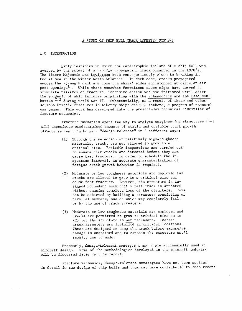
1.0 INTRODUCTION
Early instances in which the catastrophic failure of a ship hull wasaverted by the arrest of a rapidly propagating crack occurred in the 1920’s.The liners Majestic and Leviathan both came perilously close to breaking intwo at sea in the winter North Atlantic. In each case, cracks propagatedacross the strength deck and down the ships’ sides and stopped at circular airport openingsl . While these somewhat fortuitous cases might have served ~ostimulate research on fracture, intensive action was not initiated until afterthe epidemic of ship failures originating with the Schenectady and the Esso Man-hattan 2~3 during World War 11. Substantially, as a result of these and otherserious brittle fractures in Liberty ships and T-2 tankers, a program of researchwas begun. This work has developed into the present-day technical discipline offracture mechanics.
Fracture mechanics opens the way to analyze engineering structures that
will experience predetermined amounts of stable and unstable crack growth.Structures can then be made “damage tolerant” in 3 different ways:
(1)
(2)
(3)
Through the selection of relatively high.toughnessmaterials, cracks are not allowed to grow to acritical size. Periodic inspections are carried outto ensure that cracks are detected before they cancause fasr fracture. In order to schedule the in–spection interval, an accurate characterization Offatigue crack-growth behavior is required.
Moderate or low-toughness materials are employed andcracks are allowed to grow to a critical size andcause fast fracture. However, the structure is de-signed redundant such that a fast crack is arrestedwithout causing complete loss of the structure. Thiscan be achieved by building a structure consisting ofparallel members, one of which may completely fail,or by the use of crack arresters.
Moderate or low-toughness materials are employed andcracks are permitted to grow to critical size as in(2) but the structure is not redundant. Instead,crack arresters are installed in critical locations.
These are designed to stop the crack before excessivedamage is sustained and to contain the structure untilrepairs can be made.
Presently, damage-tolerant concepts 1 and 2 are successfully used inaircraft design. Some of the methodologies developed in the aircraft industrywill be discussed later in this report.
Fracture mechanics, damage-tolerant strategies have not been appliedin detail in the design of ship hulls and thus may have contributed to such recent

fractures as the large integrated tug/barge M.V. Martha R. Ingram in New Yorkharbor in 19724. But the use of fracture-mechanics concepts has been advocated.Rolfe et a15have proposed that the most economical damage-tolerant strategy forship hulls is the use of materials with “moderate levels of notch toughness wfthproperly designed crack arresters”.
In returning to the consideration of crack arrester systems to preventship hull fraccure, the problem has come full circle. The original solution tothe all-welded Liberty ship dilemma during World War 11 was to incorporate crackarresters where advancing brittle failures were to be stopped. These consistedof flame-cur longitudinal slots along the whole midship portion that were coveredwith riveted straps. Many cases are on record of cracks being arrested by thesedevices, and it is almost certain that several ships were saved from completerupture by their presence2. More refined concepts such as arresting a brittlefracture with a strake of notch-tough steel welded between strakes of standardship steel are currently favored by ship designers. However, crack arrester de-sfgn procedures are still not well developed In general.
The general objectives of this report are as follows. First, theextent to which crack arrester systems are considered in present-day ship designs,as determined by surveying marine engineers, shipyards, and regulating agencies,both in the U.S.and abroad, will be discussed. Second, a study, iden~ifyingthe basic material and theoretical concepts required for crack arrest designand setting the stage for more advanced research into the design of effectivecrack arresters for ship hulls, is given. Third, the current state of theart of crack arrester schemes was classified and evaluated to identify conceptsinvolved in their design. Fourth and last, recommendations for the research neededin this technological problem are set out and discussed.
-2-
2.0 I)ESCR1PTION OF EXISTING CRACK ARRESTER DESIGN PRACTICES
2.1 BASIC PRINCIPLES AND CLASSIFICATION Ol?ARRESTERS
The basic principle behind the use of a crack arrester is to reduce thecrack-driving force below the resisting force that must be overcome to extenda crack. The crack-driving force is the energy (strain energy, kinetic energyand external work) released by the structure at the crack tip as fracture extends.The resisting force is fracture energy which is closely related to the fracturetoughness of the material. This principle--which underlies the new disciplineof fracture mechanics--can be used to classify the different crack arrester con-figurations.
(1) Arresters that decrease the crack driving force of a pro-pagating crack
(2) Arresters that increase the fracture toughness of thematerial encountered by a propagating crack
(S) Arresters that simultaneously change both the drivingforce and the toughness.
A more detailed description of this classification together with some numericalexamples are given in Chapter 6 of this report. A quantitative discussion of thefracture mechanics parameters is given in Chapter 3.
In the remainder of the section, brief descriptions of the various kindsof crack arresters will be given.
Riveted Seam Type of Crack Arrester. (Figure 2.2.1) The continuousstructure of an all-welded ship makes crack arresters very essential. In thecase of a riveted discontinuous hull structure, a crack obviously cannot continueto propagate over a riveted seam. The easiest and simplest type of crack arrestersystem would be to use riveted seams at the vital portion of welded structures.However, the economic and labor conditions existing today preclude them becauseof the scarcity of qualified riveters.
Inserted Type of Crack Arrester. (Figure 2.2.2) In this type of crackarrester, tougher steel is used just at vital locations in the structure. It isnot economical to use-high quality material in the whole structure. The basicidea is that a tough arrester strake elevates the crack resistfng force abovethe level of the cr ck-driving force.
~This is the most common type employed in
marine applications . Also, experimental evaluations of this type of arresterhave been carried out rather extensively.738
-3-

~Riveted arrester
Hull plate /
FIGURE 2.2.1. RIVETED SEAM TYPE OF CFUACKARRESTER
FIGURE 2.2.2. INSERTED TYPE OF CRACK ARRE,STER
-4-

Patch Type of Crack Arrester. (Figure 2.2.3) The idea in this
type of arrester is to suppress the crack-driving force by introducing a compres-sion load from a patch. In same experimental investigations, the effect of thepatch reveals a decrease in K near the patch.9~10~11 Thus, when a crack runsinto this region, it will be arrested even though the basic fracture toughnessis not changed.
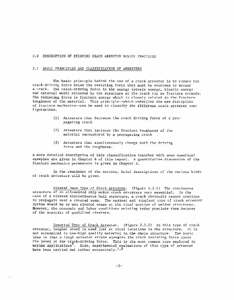
Stiffener Type of Crack Arrester. (Figure 2.2.4) The mechanism ofarresting a running crack in this system is similar to the patch-type model.Calculations have shown that if the main crack passes through the stiffener,the accompanying displacement would “beresisted by the sriffener, causingcompressive stress at the crack area and a reduction in the driving force.Test results from various combinations of a stiffeners, ma~erials, and heat-treac conditions indicate that cracks can be arresred using this concept.A T-type integral stiffener is also shown on Figure 2.2.4.
Ditch Type of Crack Arrester. (Figure 2.2.5) In this type of crackarrester, the base material thickness is thinned by machining a groove along theplate in a direction perpendicular to the anticipated running crack. The basicidea is that the fracture mode can be made to change at the reduced section byproducing a shear lip there. The effect of the shear lip is to increase theenergy dissipation mode and to change the crack propagation direction to eventuallyarrest the crack.
\
Hul
Welded Patch Type
e —-
e —-
G
c
—
Riveted
—
..—
-—
—-
—-.
—
Patch TypeFIGURE 2.2.3. PATCH TYPE CRACk ARRESTER
-5-
. STIFFENER TYPE CRACK ARRESTERS
FIGURE 2.2.5,
-6-

2.2 SHIP CLASSIFICATION SOCIETY RULES
The problem of brittle fracture in ship structures has been addressedby the classifica~ion societies mainly by using three simultaneous approaches:
1. Improvement in steels in general and the use of specialsteels in certain areas of the ship
2. Improvement in the stress analys~s of ship structures
3. Improvement in detail design to reduce stress concen-tration effects.
In the post-WWII era when the brittle fracture problem became mostcrucial, the classification societies first took independent action. As a re-sult, a large number of specifications were instituted, sometimes of a conflictingnature. In 1959, however, the societies* joined in a unification of thefr ruleswhfch was welcomed by both shipbuilders and steelmaker.
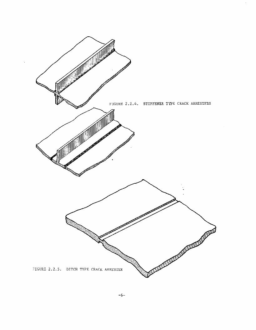
The steels are specified by the societies with the intention of pro-viding grades at strength levels with the necessary toughness for their intendeduse. The gradation of toughness is obtained by specifying the appropriate re-quirements for control of chemical composition, process of manufacture, meltingpractice and, in some cases, verificar$on by Charpy V-notch testing. The Ameri-can Bureau of Shipping steel grade specifications are shown in Tables 2.3.1 and2.3.212. For comparison, Table 2.3.3 shows the specifications for some of thesame s~eels from Lloyd’s Register of Shipping13. These specifications differessentially only in the area of Charpy V-notch testing temperatures-. The ABSspecifications require a lower testing temperature.
The applications for each steel are indicated in the various sectionsof the Rules to assure that the quality of each steel Ts suitable for the steelthickness, ship size, and particular application involved. For example, theABS requirement for Grade A steel (the lowest toughness category) may be usedUp to 51 mm (2 id thickness in low Stress areas, but would not be permittedin any thickness for the sheer strake of an ocean going vessel in excess of 137meters (450 feet) in length. For this type of service, a Grade B steel would berequired Up to a thickness of 16 mm (0.63 in), a Grade D normalized UP to 27.5 mm(1.08 in) and a Grade CS, E, or DS normalized up to 51 mm (2.0 in). These re-lationships between steel grades and ship applications are based primarily onproven service experience under a wide variety of conditions encountered bymerchant ships over the past years.
While the Society Rules do not use the terminology of crack arrester,they do specify that the tougher grades (Grade E, for example) be used wherethe arrester strakes are usually applied. Lloyd’s, for example, specifiesGrade E steel at the sheerstrake, over the longitudinal bulkheads, and at the
fiAmericanBureau of Shipping, Bureau Veritas, Germanischer Lloyd, Lloyd’s Register
of S’nipping,l~ipon‘Kaiji“Kyoiai,Det Norske Veritas, and Registro Itaiianno
Navale. -7-
,,
ORDINARY STREPJGTH HULL STRUCTURAL STEEL-.GRADEs A B D E
ICs I 0s
PROCESS OF
MANUFACTUREFOR 4LL GRADES OPEN HEARTH, tlASIC !iXYGEN, OR ELEcTRIc FURNACE
1
OEO%IDATIONAMY &~Er}, oD
EXCEPT RI MHEO
CHEMICAL
COMPOSITION(LAOLE ANALYSIS) I I
021 MAX
OBO-1 10
0.04 MAX,
0,04 MAX,
035 MA%
—SEMISKILLED
OR AI LLEO
0.21 MAX.
070-140
004 MAX.
004 MAX
0,10-0.35
KILL ED, FINE
G~AIN PRACTIC<
o 18 MAX.
0,70-150
004 MAX
004 M4X,
010-035
HEAT I 1– /VORMALIZED OVER
TREATMENT—
350 MM [1375 IN)NORMALIZED
KILLFO, FINE
‘J RA!N ?’R4CTl CE.—
016 MAX.
100.1.35
004 MAA
0.04 MAX,
0.10-035
.—
—tiILLED, FINE
GRAIM PRACTICE
0 16)4*X,
t .aQ-l ,35
0.04 MAX.
004 MAX
o 10-0,35
TENSILE TEST
TEk SILE STtiENGTH IFOR ALL GRADES. 41-50 KG/MM: 53,00 Q-71,090 PSI
YILLD PO INT, MIN. FOR ALL G8ADES< 24KG/W,lY 34,000 PSI
ELONGATION, MIV IFOR hLL GR,0E$>21YIM 200 MM(81 N), 24% 8M50MM(2i Nl\ 22% lH.5 65~[A EOUALS ARE& 0< TEST SPECIMEN
IMPACT TEST
STANDARD
CHARPY V-NOTCH
TEMPERATuRE
EN ERCY, WIN. AVG.
NO. OF SPECIMENS
— –’mc(.4F> -40 C[-40F} — —
-— 2. UK GM(20FT. LB S.; 2 EKG M(20FT, Lw1 —
— 3 FROM EACH 3F30M EACH PLATE —
40 TOtl S——. . .
-* GRACE A PLATES OVER 12,5 MU[0.301M.8
7ME w SHALL BE 2.5 *c% th411L)
TABLE 2.3.1. A13SSTEEL GRADES
-8-
—

HIGHER STRENGTH HULL STRUCTURAL STEEL
GF?A[1E5.——.-PROCLSS OF
MANUFACTURE. .. . . . .._r_—
Ef. cJxlukTlotJ
.-.—. —.cliE1.t,c.ALCOMPOSITION
(LADLE AH ALYs151
CA PBOt4%
IA AI! CA NE5E%
PHoSPHORUS%
SULFUI+ Ye
SILICON%
UIC6LL%
CWR0h411JM %
MO LVODENUM %
CC P67ER %
ALUMINUM %[Ac, n SOL” ELC,
CO LUM61UU %
(NIOBIUM)
V4KADIUM
HEAT
TREATMENT
——TENSILE TEST
TEt#S)LE 5T!+CNLTH
EL 0!4SAT IO F+, LUN
IMPACT TEST
ST AVDAHD
CHARPY V-NOTCH
TEMP[RA7URE
CP. ERG~, MIN 4VG
NO OF SPECIUEti S
SE MI- KILLCO
OR U, L’E,5
—.— ..-.
FOe ALL GRADES,
0 18 MAX.
0,90-1,60
0,04 M*X,
O 04 MAX,
-,.[ AH to\25MM[0501q.1 MAY BE SEMI-KILLED
IN WV\CH CASE 0 10% Ml!!, S; DOES HOT APPLY0.40 MAX.
0 25 MAX
0 O& MAX.
0 35 hlbx,
0,06 U*X.
O O?, MAX.
0 19 MAX
T
140? MA LI ZING REQ’3
0VER2S,5MM(I0 IN)
NO RM.4LIT!MG REQ’0, IF AL TRFATCO
OVER 12 3MM (0,50 1!+,1 oVER [25 MM(c501N)
IFNB TRE.OTED If !., TRE47ED
OVER 19 CUM [0.75 IN. )
IF V TREATFD
— . .
fOR ~? GXDDC 48-GG hG/UMz(6&+,000 -U5,00D F51)
Fou 36 G@AOE. SO–G> <:/u M’(71 000–90,000 ?$1)
FCZ 32 CRA[>E 32 KG/ M~[45,30D PSI]
FOR36 GRADE, 36 KG/k4M [5,,000 Ps()
NO I+ MALIZCD
-20 C<-4F1 –40C (-bar)
35 KG MU5F’T LB$I 35 MZM[25FT LBS)
3 FROM FLCH 60 TONS 3 FRDM Fhcti Pikrz
—.
TABLE 2.3.2. ABS STEEL GRADES
-9-

r-l.mc--l
—.—..-— —,.
——..———.
I
I
,..I
II
I#l
I Ill
.— _________
-1o-

Gr. de “EI’ whcr, L>257.lm mndtop Ioncjtudinol bulkh.od
r— ‘“-”-- - “-- ‘“not grude “D<’ —1
Grade’’E”Whoti L>228.Am
I
! ..—...-.—-l. .—.. —. T
L IGr.dc “D” whcri ithickness>20.5.1m
Grode “D” whenI ihick..ss>2O.5rmn
d
—___
7-I Grade “E”When L>228.6m
FIGURE 2.3.1.
SIPE?LIFIEDTANKER
MIDSHIP SECTION SHOWING
BASIC STEEL REQUIREMENTS
1-1I
L------- “I.—.i–.-..-..--.—1,-.--./”h LA L-’ !-Y.-J A’When L~213.4m
1
I When L~259.1 m I When L>213.4rn
When L>243.8m—~–
4
Wllen L>243%I-l. —.._.__ 1
Grade’’E”
turn-of-the bil e strakes. Figure 2.3.1 shows this requirement for a typical
tanker section15.
The American Bureau of Shipping specifies the minimum width of the sheer-strake for the midship to the length of 0.4 L using the following equations. Tnthese equations, L is the length of the vessel and b is the width of the sheer-strake.
(a) for vessels less than 120211 (395 ft) in length,
b=5L+916mmor b = 0.06L + 36 in.
(b) for vessels of 120 m (395 ft) or more in length butnot exceeding 427 m (1400 ft) in length
b = 1525 mmor b = 60 in.
The thickness of the sheerstrake is also specified in the ABS require-ments.
The stress analysis of ship structures has been improved through theyears, most importantly through the use of finite-element stress-analysis computerprograms. Many such programs are in use and some are favored by certain designagencies over others, but general structural programs such as STRUDL, STRESS, andDAISY are suited to analyze a complete ship, a section in more detail, or a singlemember in great detail. The ABS is favoring DAISY as an applicable program. Ob-viously, the use of better srress analysis techniques and the resulting improve-ment in design details to reduce stre;s concentrations will improve the brittlefracture problem.
-11-

2.3 SURVEY OF MARINE ENGINEERS, SHIPYARDS, AND REGULATING AGENCIES
In order to determine the state of current research and practice onthe problem of arresting cracks in ship hulls, a survey of domestic and foreignshipyards, design agencies, academic institutions, and regulatory agencies re-lated to
fined inmilitarysidered,were not
ship hull design was undertaken.
Before the survey was started, the scope of the effort was further re-that the data were to include only commercial ship hull designs and notships. Both fatigue and fast-fracture arrest concepts were to be con-
but special vurvose ships or materials for special applicationsto be included.
The survey asked:
(1) Do you presently design crack arrester systems forship hull structures?
(2) Have you generated experimental data to support theeffectiveness of various ship hull crack arrester de-vices? If so, are these data available?
(3) What design procedure is followed for fracture controlin ship hulls?
As a component of the foreign survey, a search was made of the openlitera~ure to identify the most current crack arrester data along with additionalagencies to be contacted. The use of the U.S. Air Force CIRC computer storagefile of Slavic-language technical literature search indicated a small number ofjournal articles pertaining to hull crack arresters.
2.3.1 Results of Domestic Survev
Approximately 30 percent of thirty-seven U.S. companies con~actedresponded. Among the topics discussed with representatives of the companies were
(a) Crack arresting techniques, if any, that are being usedor recommended in their work
(b) Experimental data on crack arresters, either publishedor unpublished
(c) Any past experiences with crack arresters.
The results indicate”tha~ very little that is new in the way of crack arrestingtechniques is currently being used by domestic shipbuilders and naval architects.Most respondents indicated that they are generally aware of and use the practicesof employing notch-tough steels and designing to avoid stress concentrators inthe hull and deck attachments. Most of those who consciously design and buildcrack arresters use the welded, integral strakes of notch-tough steel at the turnof the bilge and sheer-strake locations. But, over half of those responding to
-12-
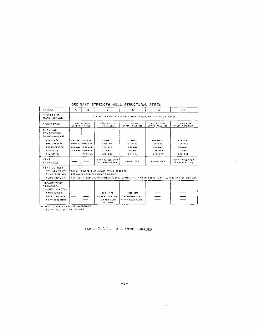
the survey have also used bolted or riveted srrakes to act as crack arresters.Nearly all of those responding indicated that they look upon ABS for dfrectionin this area.
The respondents followed the ABS requirements for material strengthsin the high-stress areas. Some shipbuilders indicated they used a grade ortwo tougher than that recommended by ABS for that particular thickness andapplication as an additional degree of conservativeness in design. The high-stress zone such as the turn of the bilge and the sheerstrake areas weretreated by using integral strakes of welded-in tougher materials by most ofthe shipbuilders and agencies.
Historically, the riveted or bolted-on sheerstrake was mentionedby many respondents as a technique used in the past. However, a fairlylarge number of respondents (about 55 percent) tndicated that on special con-ditions, this procedure is still used today. Nearly all of the respondents ad-mitted to the use of careful design and review procedures to avoid stress con-centrators in the deck details particularly. Also, nearly all the agencies andshipyards indicated that they used generally tough materials in the entire hullconstruction.
No unpublished experimental data on hull crack arresters were un-covered as a result of the survey, although most respondents were aware of thework that has been done in testing notch-tough steels for their crack-resistantproperties.
2.3.2 Results of Foreign Survey
A total of 23 foreign agencies and shipyardsawere contacted by letterrequesting information on crack arresting devices. Japan was excluded from theletter contact because Dr. K. Masubushi visited the leadlng shipyards, universities,and steel companies there to obtain their most current data. Of those contactedby letter, 48 percent responded in a fairly short time with information regardingthe problem area of crack arresting devtces. Various agencies also sent copiesof their publications related to the problem axea. A total of seven of thesedocuments were received. These documents were added to the collection of materialused in preparing this report. The seven documents received are Reference Numbers17 through 23.
The foreign survey respondents were essentially unanimous fn thatthey were using or recommending use of notch-tough steels as recommended by theregulating agencies such as Lloyd’s Register and De’cNorske Veritas.
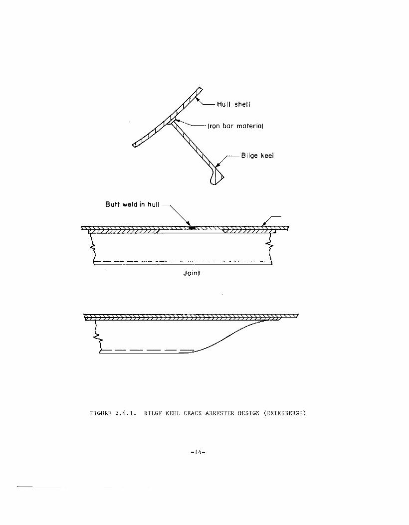
One specific design in Sweden is a weak link of iron bar materialwelded between the hull and the heavy bilge keel. This design Is intended toprevent a crack which may start in the higher stressed outer fibers of the keelfrom running into the hull shell. This design is shown in Figure 2.4.1.
-13-
Iron bar material
Butt weld in hull\
>_\\, \,\)xxxxyxxxxxx~xxkk~~x~ xx
——— —— —— —— ——
Joint
FIGURE 2.4.1. BILGE KEEL CRACK ARRESTER DESIGN (ERIKSBERGS)
—— .-
-14-

Another organization in Sweden has been using the integral notch-tough steel strakes on all their ships since 1950. For strakes above the wate~line, they have used nothing lower than Grades E or EH steels, even though theclassification society requirements may indicate that Grade D is acceptable.
As a result of the survey effort in Japan, a number of articles andpapers containing experimental data and theoretical analysis were added to thedata base. An analysis of the more pertinent publications has indicated thata variety of crack arresting techniques have been studied in Japan. Recently,however, with the downturn in the economy there, the shipbuilding industry nolonger stimulates continued crack arrester study programs. However, the Japanesehave, until recently, been more prominenr in investigating new concepts for crackarresters than has anyone else in the world.
The publications from Japan are listed as Reference 6 through 11 and14 through 16. Five types of crack arresters were examined with extensive experi-mental programs in that country.
The riveted seam is a crack arrester which is essentially no longer inuse today because of the scarcity of riveters in the industry. Bolted strakesappear to be somewhat the modern counterpart of the riveted seam. These areused to a limited extent, as best as can be determined. (Fig. 2.2,.1)
Integral crack arresters are the most cmnmon type described in theJapanese literature. This Lype of crack arrester uses a welded-in strake ofnotch-tough steel. The assumption on which this concept is based is that a crackrunning into a panel of tougher material will arrest if the toughness or thepanel width is large enough. (Fig. 2.2.2)
The patch type of crack arrester consists of a short strap of materialwelded alo,ngits short ends to the ship hull. The welding shrinkage creates acompressive load in the hull material under the strap. The strap will experiencea tensile load. The theory behind the idea is that a crack will not propagatethrough the compressive stress area under the strap provided the stress is
large enough. (Fig. 2,2.3)
Stiffener-type crack arresters were also investigated in Japan”. Thestiffener is a perpendicular strip of steel welded along the strake direction inthe hull. The stiffener on one or both sides of the base plate and running throughthe base plate were all examined in experiments. Calculations have shown thatif the main crack passes through the stiffener, the stress distribution changesand the crack can be arrested. (Fig. 2.2.4)
The ditch-type crack arrester was also investigated. This type is madeby reducing the base material thfckness by machining the groove along the plate.
The running crack intersects the ditch and it is assumed that the fracture modechanges at the reduced section where a shear lip is produced. The effect of theshear lip is to increase the energy dissipation mode and change the crack
-15-

propagation direction to eventually arrest the crack. (Fig. 2.2.5)
These designs are, as yet, laboratory studies. None are currentlybeing used in shipbuilding, except for the integral rype.
-16-

3.0 CONCEPTS FOR ARREST OF FAST FRACTURE
3.1 ANALYSIS OF FRACTURE ARREST
The process of crack arrest in structures can be discussed with LEFM(linear elastic fracture mechanics) concepts and parameters (24) although actual
problems may require more complicated elastic-plastic treatments. The LEFM re-
cognizes 4 forms of energy: (i) elastic strain energy, (ii) kinetic energy,
(iii) work done by applied forces, and (iv) the energy dissipated by crack tip
flow and fracture processes. The first 3 forms depend primarily on the crack
length, the applied loads and the geometry of the body containing the crack andare calculated by solving problems in the mathematical theory of elasticity.The net change in these 3 energies per unit area Of crack =~ension is calledthe energy release rate ~ and this is the driving force for crack extension.~
The race of change of the last energy form, i.e., the energy dissipated per unit
area of fracture, is called the fracture energy, R, and expresses the resistanceto cracking.~~ The fracture energy is a material property essentially independentof the geometry and applied loads.???
Crack-extension criteria follow from the principle of energy conserva-tion, namely, that the energy release rate must be balanced by the fracture
energy. This statement means that crack extension (growth of a stationarycrack) or continued propagation of a moving crack are only possible when
(3.1-3)
Equivalently, no crack growth is possible or, for a propagating crack, arrestmust take place, when
tstationary crack
(2) &=_~+wdA
fast propagating and-dT+dW
& .-~ ~ ~
arresting crack (25)
(3.1-1)
(3.1-2)
where U is the strain energy, T the kinetic energy, w the work performedon the structure by the surroundings, A the crack area,
‘or ‘hed~va&-ation of & for a fast propagating or arresting crack, the terms
and ~ ~’ dAmust be evaluated from fully dynamic analyses.
?? The fracture energy for the extension of a stationary crack is usuallyreferred to as &c, the critical energy release rate.
ttt It is, in fact, a basic postulate of LEFM that all inelastic ir-reversible energy dissipation processes that accompany crack extensioncan be included in a single material property that is possibly a
function Of the crack speed, but is independent of the crack length,the applied loads, and the external geometry of the body. The extentto which this is true really determines the applicability of LEFM.
-17-

&’<R (3.1-4)
for all values of R.~ These criteria, as well as the role of srrain energy, and
kinetic energy are illustrated schematically in Figure 3.1.1 for the case of acrack that is propagating in a structure under fixed grip conditions.”~~ In this
‘u first Increases with crack extensioncase, the strain energy release rate - _
and then decreases when the crack lengtf; a, becomes large relative to the dimen-sions of the cracked member. Figure 3.1.1 shows that the criterion for the onsetof fracture @ satisfied when a = a . At this instant, the crack begins to ex–tend rapidly. The crack continues to propagate until a = a , where the criterionfor crack arrest is sa~~sfied. In the initial stage (the ii%tervalAB), the strainenergy release rare - _ supplies the crack driving force and imparts kinetic
energy to the body (se$-Ashadedarea in Figure 3.1.1). In the latter stage (the
interval BC) the crack continues to propagate even though - ~ is less than Rby virtue of the kinetic energy recovered from the structure.‘%uring thi~Tperiodboth the strain energy release rate and the kinetic energy release rate, ~contribute to the crack driving force.
Detai~~d dynamic calculations of this type are available for beamlikeconfigurations . The example shown in”l?igure3.1.2a and 3.1.2b for a rectangulardouble-cantilever-beam (DCB) test piece under fixed grip conditions, illustrates~-hatabout 85% of the kinetic energy imparted to the specimen is returned to thecrack tip under these conditions. This represents 30X of the energy spent infracturing material and produces a disproportionate amount of crack extension be-cause kinetic energy is only part of the driving force. At the same time, itshould be noted that very little kinetic energy return is anticipated for smallcracks in Large bodies that approximate the crack-in-an-inffnite-body idealization, 27
In other words, the contribution of the kinetic energy release rate is a variablethat depends on the geometry of the structure. There is a need for dynamic analysesthat define the amount of kinetic energy return in different classes of problems.
T Note that the condition where& exceeds R is not possible because i~would violate the energy balance principle. The stationary crack re-
lation, inequality (3.1-4), it might be pointed out, does not violate
the energy balance, The reason is that in this case, the crack growtharea corresponds to a virtual crack extension only.
dwtt TJnder fixed grip conditions ~ = O, and the 3 criteria reduce to the
following expressions:
1. Criterion for the Onset of Fracture R< - ~ (3.1-5)
2. Criterion for the Continuation ofFast Fracture
~< d@- ~
dA dA(3.1-6)
R > _ duD dTD3. Criterion for Fracture Arrest
z- =“(3.1-7)
-13-

c
(
IT HIII Kinetic energy imparted to test piece
I I Kinetic energy returned to crack tip
xxxx G -––– -dU/dA
—R —. — -dTidA
dl!llllmllll..-....+.x.x%
T
A B ~c\
,4x
>’~~“+
,/”- \-
(’—
/—
I ‘\/’
(crack‘\ -—.-’” (crack
stable)(crack. propagation)
stable)
G<RI G=R
G<R
a. Ua
Crack Length ~
FIGURE 3.1.1.
particular grip displacementcould grow slowly by fatiguements that do not exceed the
SCHEMATIC REPRESENTATION OF THE COMPONENTS OF THE CRACK DRIVING FORCE, G,THE FRACTURE RESISTANCE R AND CRACK VELOCITY V ATTENDING THE FRACTURE OFA STRUCTURAL MEMBER UNDER FIXED GRIP CONDITIONS. The lower part of thediagram shows the velocfty of a crack initially of length ao. Cracks
smaller than an or larger than aa cannot grow spontaneously for rherepresented because & < R. such cracks
(u~der the action of cyclic grip displace-value represented) or stress corrosion.
-19-
oaao
/
2s. 58. ?$, ,00, 1>>.
TIME (MICROSEC)(a)
lam. *00. *O*, ● O*. Sea.
TIME (MICROSEC)(c)
FIGURE 3.1.2.
1.
StrainEnergy.vL,t2
u
L
A-—
Z*. .0. ● O.
a-ao(mm]
(b)
.-
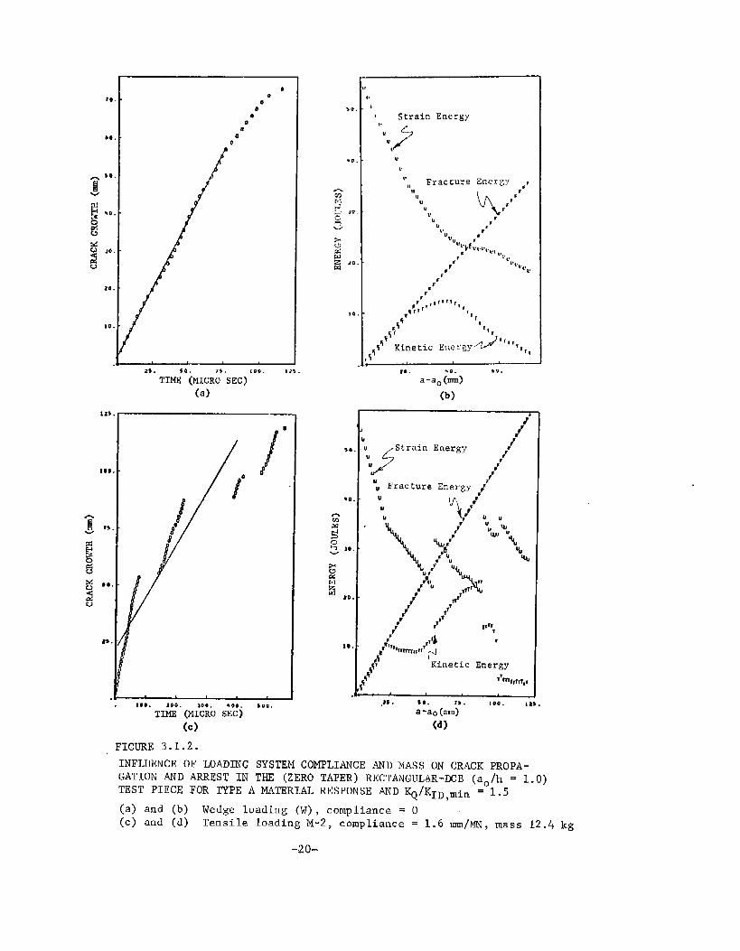
INFLUENCE OF LOADING SYSTEM COMPLIANCE AND MASS ON CRACK PROPA-GATION AND ARREST IN THE (ZERO TAPER) RECTANGULAR-DCB (ao/h = 1.0)TEST PIECE FOR TYPE A MATERIAL RESPONSE AND ~/KID,min = 1.5
(a) and (b) Wedge loading (W), compliance = O(c) and (d) Tensile loading M-2, compliance = 1.6 mm/MN, mass 12.4 kg
-2Cl-
The mass and compliance of the loading system are also important factors which
enter the problem by way of the external work term ~.d.#.
Figures 3.1.2a and
3.1.2b, give the results of calculations for propaga ~on and arrest when thegrips are fixed and ~= O. These may be compared with Figures 3.I.2c and3.1.2d. for rectangu%DC B-test pieces when the grips are not rigidly fixed,and possess the mass and compliance t
%ical of a laboratory loading system.
In this case, the external work term _makes periodic contributions to thecrack driving force causing the crackdA to reinitiate a number of times. The
extent of propagation is nearly twice the value obtained under fixed gripconditions.
These concepts serve to distinguish between the two principle strategiesfor arresting a crack in a monotonic structure. Cracks can he stopped either by:
o Increasing che,fracture resistance, R or
e Decreasing the crack driving force &
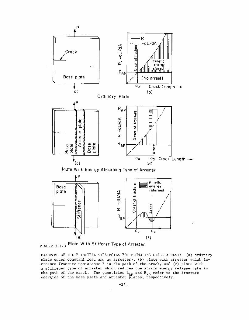
in the path of the crack. Two strategies are illustrated in Figure 3.1.3 fora plate under essentially constant load. The strain energy term, . ~ , increasesmonotonically under ‘ches~conditions (see Figure 3.1.3b). This mean~Athat thecrack will not stop w“$thout an”ar~esting device. The crack can be arrested by “ - ‘the first strategy of inserting a tough arrester with a high R-value in the pathof the crack (Figures 3.1.3c and 3.1.3d).
‘he second “rate%s ‘s ‘mp’emen’ed byattaching a stiffener which produces a local reduction in - — (Figures 3.1.3eand 3.1.3f). In both cases some kinetic energy return is shdk schematically
and will affect the performance of rhe arrester.
In principle, the rigorous application of these &once ts to the de;~gnof crack arresters is straightforward. d{ dTThe energy components ~
‘z, and —
dAare calculated for the structure and loading of interest. The fracture energyof the hull plate and~or arrester plate are measured in the laboratory. Together,Lhese quantities define the width, spacing or cross section of stiffener orenergy absorbing arresters. In practice, the task is a difficult one. Methodsof evaluating the energy components from dynamic analyse~8 (see Chapter 6) areonly now being developed for simple structural elemert~s . Their applicationto the complex hull structures will not be routfne. For this reason, a numberof simplified treatments of crack arrest based on static analyses have currencyand these are reviewed in Sections 3,3 and 3.4 of this chapter. The evaluationof the very large R-values required of arrester marerials also presents special,unresolved problems which are examined in Chapter 5.
-21-
L
crack
.,
Base plate
t(a)
tp
Ordinary
mEE!LJa. Crack Length
(b)
(d)
Plate With Energy Absorbinq Type of Arrester
+PI
Base ‘$plate
\
\
FIGURE 3.1.3
FXAMT’LES OFplate under
e)
B Kinetic
energy
returned
4
/’
%al
/’
: /
‘/
a. aa
(f)
Plate With Stiffener Type of Arrester
THE PRINCIPAL STRATEGIES FOR PROMOTING CRACK ARREST: (a) ordinaryconstant load and no arrester), (b) plate with arrester which in-
creases fracture resistance R in the path of the crack, and (c) plate witha stiffener type of arrester which reduces the strain energy release rate inthe path of the crack. The quantities RBI and Rw refer to the fractureenergies of the base plate and arrester p ates,Lrespectively.
-22-

3.2 CRACK ARREST MATERIAL PROPERTIES
The treatment of crack arrest is further complicated by the variationof the fracture energy R with crack veloci~y and plate thickness. Eftis andKraft 29 have deduced R-values from the Barton and Hall 30 wide-plate, ship-steel experiments. Their results, which reflect low-energy cleavage fractures
below the nil ductility temperature (NDT), indicate”that R-values first decreasewith increasing velocity, display a minimum at a finite velocity, and then in-crease dramatically for crack velocities in excess of 600 ms. Recent resultsfor low-energy fibrous fractures in AISI 4340 steel are reproduced in Figure3.2.Ic. Here the fracture energy Tncreases monotonically with crack velocity.Since tough arrester materials also display the fibrous mode, it is possiblethat their minimum fracrure energy values will also be observed at zero velo-city.
Rigorous calculations of fracture arrest must take into account thevaria~ion of R with velocity and an arrest criterion based on the minimum frac-ture energy Rmin (see Figure 3.2.la):
It therefore becomes necessary to distinguish
(3. 2-1)
among several different valuesof the fracture energy (and their equivalent fract;re toughness values).
Symbols and definitions of different quantities employed here and abroad arelisted in Table 3.2.1. Note that the criteria for crack extension can also beexpressed in terms of the stress intensity parameter K and various fracturetoughness parameters as explained in ~he footnote to Table 3.2.1:
criterion for onset of crackextension K=K
c(3.2-2)
criterion for continuingpropagation K=
%(3.2-3)
crirerion for crack arrest‘< %,min
(3.2-4)
The subscript I (i.e., GIC, KIC, ~1 , K1a) is introduced to distinguish energyand toughness values measured when ~he crack-tip plasric flow fs predominantlyplane strain* as opposed to so-called “plane-stress” values which reflect signi-ficant amounts of through-the-thickness deformation. The plane-strain values areindependent of thickness while full shear (plane-stress) values of tough materialsdisplay a modest thickness dependence Kc = tn,
0.25<n< I.O 33-36 ~where t is the thickness and
According to $STM E399, plane strain is obtained when the plate thickness
(-)
t 22.5 KIC where ~y is the yield stress. A similar expression can beoY
expecred to apply to fast running cracks provided Oyis interpreted asthe dynamic yield stress.
-23-

I ,:
I 110r ● * O Kd El!i, a K,u III, Bo,,on B MO!,,
U.211shin01.,,.,R,&.,a..-. . . .. .. .. . . .● Bums a Biltk, i020 %!teI,.50.c01 ~
0 Vmlo
CrackVelocity_Crock Vtlocilym m,- 1
Frocl!on of Bor Wove Speed,v/C.
o 005 010 0,15
5
F-Legcnd
4
::
➤0 Arresl length
20 ;~
f 50 6 Crock veloc,ly 10 g
g Cl Remilloliono
5~
. .. .1000
Crock VelocII y, m/s
FIGURE 3.2.1. EXAMPLES OF THE CRACK VELOCITY DEPENDENCE OF THE FRACTURERESISTANCE R AND THE CORRESPONDING PROPAGATING CRACK TOUGHNESSKD : (a) schematic of a dependence with a minimum showing kinand KDmin, (b) results for cleavage fracture of ship plateafter fiftisand Krafft 29 and Barton and Ha~~ 3° and 1020 steelafter Burns and Bilek 32 ~ and (c) result~lfor flat fibrousfracture of 4340 steel after Hahn, et al
-24-

TABLE 3.2.1. SUMMARY OF FRACTURE ENERGY AND EQUIVALENT FRACTUREToughness VALUES RELATED TO THE CRACK ARRESTPROBLEM
DEFINITION FRACTURE ENERGY(a)
FRACTURE TOUGHNESS(b)
1.0 The fracture energy and toughnessat the onset &f unstable crackextension and for essenEi:llyzero crack velocity
1.1 Values corresponding toslow loading rates
1.2 Values for high loadingrates
Kc
‘d
2.0 The minimum fracture energy andtoughness
2.1 Values derived from R Kdynamic analyses
min D,min
2.2 Estimates derived from &a Kastatic analyses of anarrested crack
2.3 Japanese practice for &c Kcestimates frum staticanalysis
3.0 The fracture energy and toughness RD%at an arbitrary crack velocity
tThe fracture energy of an extending crack (i.e. &c, Rm.n, R, &a, etc.)
1/2(V)[E#!l-V$~i~i’w&~eis related to a corresponding fracture toughness parame er
KD ~in, KD, Ka, etc.) by the expression K = A
Af/](v) = , when ~=o, , ~ *,,2(V)A $ is a function of crack velocity chat depends on Cl, C2 and Cr.and
< 1.1 for OS V< 1500 ins-l forsteel. 27,39
(a) Common units: in lbs/in2 = 1.75 J/m2.
(b) Common units: Ksi’fi = 1.10 MN/m3/2
= 1.10 MGr = 3.54 Kg/mm3/2.
(c) In all but the more recent Japanese technical papers the quantities &cand Kc are so defined that &a = T&c and Ka = Vflc.
_25-

The quantities~ and Kd in Table 3.2.1 have been related to R . and
>~!~~t~~~~~s~~t~~~and strain-rate environment of a rapidly loaded stationaryd 37 and Krafft 38 . These workers propose t!&~ the
crack and a propagating crack, and the fracture energy in these two cases arethe same provided the stress rate K and ~he crack velocity V are comparable:
&a(i) = R(V) (3.2-5)
A sim le ela7 -3F2~_l g
ic ar ument suggests that che stress rates K = 105 MNm-3/2S-1
to 10 MNm are comparable to the crack velocities of V = 1 ms ‘1 to
100 ins-lcorresponding to R . . Accordingly, the ~d-v:lues measured at thesehigh rates of loading are amk~asure of R . . Results m Figure 3.2.2 lendsome support to this concept which is no~~~ell established.
3.3 THE STATIC, ARREST TOUGHNESS (& Ka) ANALYSISd’
Irwin and Wells42 41,43-45
and Crosley and Ripling hsve proposeda simplified treatment of crack arrest. Their approach embodies the same basiccrack arrest criterion, i.e.,&< Rmi , but approximates the driving force for con-tinued crack propagation with the va~ue appropriate for a stationary crack of thesame length.* The statically evaluated energy release rate at srrest, .& , is takenas a close approximation of Rmin , and the criterion for crack srrest giv~n in Equa-tion (3.2-1) reduces to:
or
Ka>K
(3.3-1)
(3.3-2)
where K and K are the corresponding stress-intensity parameters and K is
called ~he srrest toughness.a
According to the static arrest ‘cheery,b or K are geometry in-dependent properties of material that coincide with theavalueaof& or K at thepoint of crack arrest. This concept appears to be valid in some cases. For
41 find that K1aexsmple, Crosley and Ripling values of reactor grade A533Bsteel are independent of the crack jump distsnce in a contoured DCB specimen(see Figure 3.3.1). They also report that cracks initiated in brittle weldmentsinserted in single-edge-notched -(SEN) test pieces of the same material arrestat the same value of K 45 St~~i;~ of various stiffener type of srrestersby Yoshiki, %“Kanazawa an Machida 3 in Japan also lend support to the static-K
approach. As shown in Figure 3.3.2, predictions of arrest based on K measurement:(referred to as K in Japan) and statically calculated K values were ?ound to bein good agreementcwi~h experiment.
k In o~~er words, the kinetic energy term - ~ is neglected and - ~ + ~
i.sevaluated using static analyses.
-26-

?60‘-’~– -T I I I I+
240– A533Gr. B Class 1 Plate—
● lTLTSpcimen
220“ o nCT Sp$cimenSteel Plate 12[’Thick (HSSTPlate 02) —
200-A 4TCTSp5cimenu 8TCTs~cimen 125°F –
180–
160–
140 -
120- A
100–
80- -50”F+5WF4
60‘A
*
4o–
20
0 I I I I T .X11 101 102 103 104 105
FIGURE
-.k-- ksi msecond
3-2.240
comparison OF Kid-MEASUREMENTS OF SHABBITS WITH KTa-MEASURE -
MENTS BY CROSLEY AND RIPLING 41 , BOTH ON A533B STEEL. The graph
shows that K1d(i- 5.105), obtained by extrapolation correlate tosome degree with K1a-values.
FIG1.JRE3.3.1. INFLUENCE OF THE CRACK
JUMP DISTANCE ON THE ARREST TOUGH-NESS, KIa, OF A533B STEEL AFTERCROSLEY AND RIPLING 41 .
-27-

K [k@’mf#mll
IAKP-I-15 (RJlti. ~p:150nun, bp:60mn , tp:13mm) Tmm rc)
d m=16kg/rd i.-33
100-‘Khithorrustw
k 65ti’mkdfrwIDT.
— c*%o 02 04 06 08 10 12 14 16 18 ZO
xl 1031532 m2m 333 a4034~ m — o(m)
(a)
K(kgd.~J
IAKPR-4-10 (k@r: f :100rmn. bp=40mm .fp:13mm . il*Z&wrI)
AKPR-4-15 ( - l=150mm. . . . . . )
10)
‘+/F)’’’’;’;;;r;’’’’’’’’’’’’’’’r;’’’’;’;’;;;;),
0 o? 0,4 06 0,8 10 K 1;4 1,6 1,8 2P-cm“b
Iil{ttttla500-’t--_-L——-
t
R‘1 ‘ A
-.——;----
[
M*
Wd
@ Welded Mich TYJC
ttttttttt
r
(b)
,/’}60
.
tttttttttmi500““
t,81,W
.
,1
Ii.;.
rofQ+--- id
(c) Riveted Stiffener Type
(c)FIGURE 3.3.2.
COMPARISON OF EXPERIMENTAL RESULTS FOR STIFFENER-TYPES OF CRACK ARRESTERSWITH PREDICTIONS FROM THE STATIC ANALYSIS AFTER YOSHIKI, ET AL 47 : (a)welded notch type stiffener, and (b) and (c) riveted stiffeners.
-28-

At the same time, there is a growing body of evidence showing thatthe st~~i~8a&ysis of arrest is not generally valid. Dynamic calcula-tions 9 3 show that by neglecting the kinetic energy term both thedriving force, ~,and R . are undervalued by st~ti~l~naly~~~chR~~~~~ ~~e~n_
sented in Table 3.3.1,m$ylustrated that the rat~o-n
variant and close to unity if the static theory is valid) actually depend onthe loading system and on the geometry. For this reason, the errors containedin a static analysis of arrest in a structure may or may not be compensatedfor by the discrepancy between&a and Rmin.
3.4 APPLICATIONS OF THE STATIC TOUGHNESS ARREST APPROACH AS USED INJAPAN
Serious difficulties of the type described in Section 3.3 have, infact, been encountered in the more recen~ba~alyses of large-scale ship-platearrester model tests performed in Japan ‘ . As shown in Figure 3.4.1, ar-rest was observed in the models even though the statically calculated K valueswere twice Ka . Japanese workers believe that the discrepancy can be tracedto dynamic features attending the propagation of long cracks which invalidatethe static analyses. We believe the discrepancy may also be connected withtheir imprecise treatment of the loading system (the ~ term) and with their
Ka measurements. fAThe Japanese investigators have dea t with this problem bypostulating an effective crack lengrh and effective stress intensity.
=0.la+190mmaeff
(3.4-1)
and
which contains anthe K levels at
Keff ‘ ~ laeff (3.4-2)
empirical correction designed to lower calculated K values toarrest. Fimre 3.4.1 illustrates that the correction is
reaso~ably successful when applied VO the experiments from which it was derived.However, the general applicability of this correction (e.g., its application tothe stiffener experiments in Figure 3.3.2 which can be explained without acorrection) is open to question.
3.5 FRACTURE ARREST APPROACH AS USED IN AIRCRAFT STRUCTURES
The riveted skin-stringer design of many aircraft structures isbasically a crack-arrest structure. Ai”rcraft are presently designed to arresta two-bay crack; i.e., a crack originating at a stringer is to be arrested atthe two adjacent stringers. The Air Force has recently issued MIL-A-83444,“Airplane Damage Tolerance Design Requirements”, In which this arrest require-ment is formalized.
.-29-

TABLE 3.3.1. COMPUTATIONALRESULTS FOR CRACK ARREST IN THEDCB SPECIMENFOR VARIOUS DIFFERENT GEOMETRIESAND INITIAL STRESS INTENSITYFACTORS 48
ComputationalResultsInitiation Speed–Dependent Speed-IndependentConditions Fracture Energy Fracture Energy
aoih Kq/KIC crlh ~lco KE/K1m ar/h ~/Co” Kn/K1m
1.0 1.00 1.45 .074” 0.89 1.00 ,0 1.001.0 1.25 1.75 .094 0.86 1.40 .086 0.821.0 1.50 1.95 .104 0.88 1.90 .149 0.641.0 1.75 2.05 .116 0.95 2.55 .192 0.471.0 2.00 2.15 ,122 1.01 3.35 .203 0.351.0 3.00 2.60 .146 1.13 6.70 ,262 0.151.0 4.00 2.90 .163 1.26 * .308 *
2.0 1.00 2.90 .063 0.80 2.00 0 1.002.0 1.50 3.60 ,097 0,83 3.50 .097 0.612.0 2.00 4.20 .115 0.85 5.15 .156 13.422.0 3.00 5.35 .138 0.84 * .214 *
2.0 4.00 6.55 .149 0.78
3.0 1.00 3.55 .067 1.08 3.00 0 1.00
3.0 1.50 5.60 .089 0.73 4.8o .072 0.673.0 2.00 6.95 .106 0.66 6.90 .124 0.47
* Crack did not arrest,
-30-

~a!— —..,w’
~-. — —
.)—— .
[email protected]?Z,,!._ .@_.
L—.–w.;
.[ ‘_50Q.-.~750 13w.____-:L5.0 —_——. —
2400
Specimenforbuttwelded-typecrackme$termodel
(a)
Tyw A750A’ 55oE*
r $b::~r plate
t
Arres!er vla!e
1000—.
A*LO‘“ E“.~O
1 I0 200 400 600 BOO 1000 1200
Crack Ieng!h mm
(c)
TYW A750A’ - 100E*
Arrcs!tr WC
[ ‘--s!af$gq:!~-__ + + SU7PI r.la:,
.—10DO-
-..—A- IO; E* <0) As 30
---- .ha:ut #,”c”!.900- — Etlcc!Iw I- VJIUC‘8. -C,T’
: /’
g ~oo ./’
---
:/ “
)
~ 400-/
.<-/ d, 13tiEmm: O’C AB E*
200- --z + 13kg mm:. –4’C AA E* K,~------— 13kgmm?,–10.C CF E“
I
o 200 400 600 EGO 1000 1200Crack length mm
(b)
TYPeA750A”. 300 E- Tynt A750A
t
Slar[ef p[a:e
1000 – “A*30, A30, D30
>,EEE
:W
800
600
400
200
300E. T,x A750D - 300E
A,resw PIJ!t $LKI[ Dld!e
] T
E“”3.O .-E 30 A“ 30 .A 3(
----- *- “al.{ “ ~ /“D JO
— Elfecwe k value a.’C, ””J“”
Io 200 400 600 8a0 1009 1200
Crack Ienuth mm
(d)
FIGURE 3.4.1. COMPARISONS OF EXPERIMENTAL RESULTS FOR LARGE, WELDED-TYPE, ENERGYABSORBING CRACK ARRESTER MODELS WITH CALCULATIONS BASED ON THE
STATIC ANALYSIS AFTER KULARA, ET AL 7 : (a) test piececon~igura~ion, (b)-(d) results for different materials.

So far, the static analysis of arresters has proven satisfactory foraircraft structures, because (1) fast crack growth in aluminum alloys is still
rdatively S1OW (in the order of 500 ftlsec) and (2) thin aluminum plates ShOWan increasing crack resistance as the crack extends. Nevertheless, MIL-A-8344&prescribes that a safety margin of 15 percent should be taken on the staticanalysis to account for possible dynamic effects.
Analysis ~~thods for stringer-skin configurations have been d~~e$:pedby Ronmald~, et al , poe 50,51 Vlieger 52353 , and Swift and Wang ‘ .Both finite-element methods and cl;sed-form solutions can be used. The basicprocedure is outlined in Figure 3.5.1. The stiffened panel is split into itscomposite parts. Load transmission takes place through the fasteners. As aresult, the skin will exert forces F
e~&F2’ ‘tC”’on the stringer, and the stringer
will exert reaction forces F‘2’
, on the skin. This is depicted inthe upper line of Figure 3.5~~.
The three cases have to be analyzed separately. Compatibility requiresequal displacements in sheet and stringer at the corresponding fastener locations.These compatibility requirements deliver a set of n (n is number of fasteners)independent algebraic equations, whic~6can be solved numerically to derive thefastener forces. According to Swift , 15 fasteners at either side of thecrack need to be included to give a consistent result. A proper analysis includesthe effects of (1) stiffener yielding and betiding, (2) fastener yielding, and(3) fastener-hole deformation.
For the arrest analysis53
consider a skin-stringer combination asin Figure 3.5.2 (top). The displacem~nts of adjacent points in skin and stringerwill be equal. Let a transverse crack develop in the skin. This will causelarger displacements in the skin, which has to be followed by the stringers. Asa result, they take on load from the s,kin,thus decreasing the skin stress atthe expense of higher stringer stress. Consequently, the displacements in thecracked skin will be smaller than in an unstiffened plate with the same size ofcrack. This implies that the stresses in the stiffened plate are lower andthat the stress intensity is lower. The closer the crack tip is to the stringer,the larger the load-sharing effect,
If the stress intensity for a central crack in an unstiffened plateis K =~~fla, then the stress intensity for the stiffened plate is K = !3u~na.
The reduction factor, ~ , becomes smaller when the crack approaches the stringer.Since the stringers take load from the skin, their stress will increase from o
to Lo, where L $ncreases when the crack approaches the stringer. Obviously,
Q<61andL~l. Their values depend upon stiffening ratio, fastener stiffness,
and crack size. For a qualitative discussion, it may suffice to let B and L vary
as in Figure 3.5.2.
Now the arrest diagram for a simFle panel with two stringers and acentral crack can be constructed. Fast crack extension in an unstiffened platewill take place at a stress given by DC = K l~~a, represented by the lower linein Figure 3.5.3. For the stiffened panel, ~he stress for fast cra~k growth can
be calculated as Dc = Kc/~ (~a. Knowing 8 from the static analysis. Gc can
-32-

be calculated. It varies with crack size as shown in Figure 3.5.3. Since6 decreases if the crack approaches the stringer, the curve turns upwards forcrack sizes in the order of the stringer spacing.
The possibility of fastener failure and stringer failure should be con-sidered also. Here, only stringer failure will be discussed. The stringer willfail when its stress reaches the ultimate tensile stress, ~ of the stringer
material. As the stringer stress is ~, where ~ is the nom~~~l stress in thepanel away from the crack, stringer failure will occur at osf given by ~sf = outs.
Using L as depic~ed in Figure 3.5.2, the panel stress at which stringer failureoccurs is given in Figure 3.5.3.
Now consider a crack of size al. At a stress O1 fast crack growth occurs(point A). It will run to point B where it is arrested (because K will be lowerthan K again). Further increase of the stress will cause the crack to propagate
Ein a s able manner co C, where again fast fracture would occur at a stress D ..
If the crack size is az, a stress uzis required for fast crack growth.— Arrestwill not occur because o > u .
2
It has been outlined that$ and L depend upon stiffening ratio. Thisimplies that the diagram of Figure 3.5.3 is not unique. It shows the casewhere plate failure is the critical event. In other cases, stringer failuremay “becritical; this is so when the stringers are relatively small in sectionas compared to the bay sectional area. This is depicted in Figure 3.5.4. Acrack of size a becomes unstable at a stress D3. It will run to point D wherethe stringer will fail. Hence, it will not be arrested. The highest stress forarrest,~ , is now determined by point E as shown.
Many large panel experimental data are available to show the adequac32,53of the analysis procedure for aircraft structures. Some test data by Vlieger
are shown in Figure 3.5.4. Thecase of a short crack fracture,arrest at the stringer. Longerthen sudden fast crack growth.which the panel could be loadedcurred.
test data confirm the predicted behavior. “Ininstability occurs at a stress too high for crackinitial cracks showed some slow crack growth andCra~k arrest occurred at the stringer, afterto o (horizontal level) where final failure oc-
3.6 DYNAMIC ANALYSIS OF CRACK PROPAGATION AND CRACK ARREST
The problem of arresting a rapidly propagating crack is of great con-cern in several different kinds of engineering structures. These have in commonthe feature that unchecked unstable crack growth would have catastrophic con-sequences. They include aircraft (as discussed in the preceding section),nuclear pressure vessels, bridges, and gas transmission pipelineslin additionto ship hulls.
There is currently no universally accepted theoretically-based design
approach to ensure crack arrest. A static approach, or, what amounts to thesame thing, the “arrest toughness” or K approach, is almost universally employed.This approach is based on the idea thatl~rack arrest is just’the reverse ofcrack-growth initiation. However, there is a body of experimental results
-33-

\ .—. — .—-— . /;
-1
t:
Iml
.
b-l---- ● --””l-b
+
.* .*....
II
b—r---l-b
300000000
00000000
+
+
.2CUH
.Cn
!2
-34-

u
1
I
I ItI
— 20
FIGURE 3.5.3. ARREST DIAGRAM FGR STRINGER CRITICALCASE
!
I40
F
30
20
00
Arrested
cracks
40 80 120 1602a,mm —
FIGURE 3.5.4. ARREST DATA BY VLIEGER FORALUMINUM ALLOY PANELS WITH Z-STIFFENERS

together with a rigorous energy-based method of analysis that has shown thatcrack arrest is a dynamic process that must be treated wftk,in the context of adynamic fracture-mechanics theory. This work, originated at Battelle with priorShip Strut..~g~Committee support 57 and continued on behalf of otheragencies Y includes several generalizations of the static approach. Theseinclude
● A kinetic energy contribution
● Inertia effects
● Dependence of fracture toughness on crack speed.
The primary purpose of this section of the report is to demonstrate tha~ stat-
ically based analyses can dangerously overestimate rhe capacfty of a structureto arrest a rapidly propagating crack. It will further be shown that evenanalyses taking full account of the essential aspects of dynamic fracturemechanics can still be inadequate for predicting crack arrest ‘Jhenother vitalfeatures of the pro~~e~gare neglected. In particular, the otherwise admirableanalyses of Freund ~ cannot cope with stress waves reflected back to thepropagating crack tip from the specimen boundaries. This feature is not onlyimportant for experimental work carried out using small laboratory size testspecimens, but would also be important in analyzing crack arrest devices.
Large-scale numerical computations are beyond the scope of the work re-ported here. This p~ecludes complete analyses of the various candidate arrestersystems. Nevertheless, it is important to have some quantitative evidence on thedynamic amplification of the crack driving force. This must be done %n order toconvincingly demonstrate the fact that static analyses of “crack arrest can signi-ficantly overestimate the capability of-a system to arrest a rapidly propagatingcrack. To accomplish this, some calculations were made with an existing computermodel that was developed on an earlier Ship Structure Committee program to analyzecrack propagation and crack arrest in the double cantilever beam (DCB) test speci-men57 . Mile hardly representative of most engineering structures, the DCBspecimen geometry does lend itself to performing dynamic crack propagation-arrest analyses. Such analyses currently cannot be made for actual structureswithout performing large-system numerical computations. Hence, for the purposes
of this report, the existing DCB analysis model was a natural vehicle, if notthe only possible one, to demonstrate the differences between static and fullydynamic fracture mechanics concepts to evaluate crack arrester systems.
In this section of the report, the governing equations for the DCB
specimen dynamic analysis procedure are first outlined. Next, a brief descrip-
tion of the alternative approaches is given where it is shown that, for crackarrest predictions, the conventional quasi-static approaches can be representedwithin the confines of a “quasi-dynamic” approach. Finally, some sample cal-
culations are performed to contrast the quasi-dynamic and fully dynamic predictionsfor crack propagation and arrest in DCB specimens. This will set the stage for
the analyses reported in Section 6 on the various types of ship-hull crack ar-resters.
-36-

3.6;1 Governing Equations for Dynamic CrackPro~a~atlon in the DCB Test Suecimen
The starting point fordynamic crack propagation in theof elasticity with inertia termsgeometry of Lhis specimen can beexplicity considered. These are
the derivation of,the equations governingDCB specimen are the equations of the theoryincluded. Because the peculiar “beam-like”exploited, only four equations need to bethe two equations for motion along the length
of the beam (the x direction) and two Hooke’s law equations. The two equationsof motion are given by
2aux ~~ aT a Ux
ax—+ —%*=P-
ay atz
and
a~xz a~ ao a2uz+--lz++=p— .
ax ay at2
The two constitutive or Hooke’s law equations tha~ enter into the analysisare given by
(3. 6-1)
aux
E—ax=Ox-
V(o’y+ Oz)
and
a~x auz Txz
az ‘== G “
(3. 6-2)
(3.6-2)
(3.6-4)
In the above equations, E, G,v and p denote Young’s modulus, the shear modulus,Poisson’s ratio, and the density, respectively; Ux and Uz are displacement com-ponents; are stress components; and t denotes time.
‘x’‘y’‘z’‘Xy’‘X2’‘Yz
Problems in which two-dimensional spatial variations and time variationsboth enter are difficult and, generally speaking, inappropriate to treat in a pre-
liminary phase of an investigation. The simplification that can be introduced tomake the mathematical analysis more manageable is made by introducing cross-sec-tionally averaged dependent variables into the analysis. If A = A(x) is the areaof the DCB specimen cross section at any axial position x, then these new variablescan be obtained formally as follows. The deflection w = w(x) is
-37-

(3-6-5)
The rotation Y = Y(x) is
I ‘Af ‘Ux dydz .~=.~
The shearing force S = S(x) is
s = jA~ Txz dydz .
The bending moment M = H(x) is
By Operating on(3.6-5) throughDCB specimen in
(3.6-6)
(3.6-7)
Iiquatfons (3.6-1) through (3.6-4) by ]A~ dydz and using Equations(3.6-8), after some manipulation, the equations of motion for theterms of the cross-sectionally averaged variables are found to be
as a 2W
G–kew=pA—
at2
a2Yg+krY.s==PI—
arz
_E1~=Max
&_y_sax K GA
(3.6 -9)
(3.6-10)
(3.6-11)
(3.6-12)
-38-

where I is the moment of inertia, k and k , respectively, represent the ex-“Etensional force and bending transnu ted ac$oss the crack plane, and K is a
constant which depends on ‘theshape of the cross section and on Poisson’s ratio.Of course, k = k = O where the specimen is cracked, but are functions of thespecimen geo$etryrand elastic properties otherwise.
Now considering that A and I are functions of x and eliminating Mand S from Equations (3.6-9) through (3.6-12), it is found ‘chat
and
(3.6-13)
(3.6-14)
specializing to a rectangular cross section aLlows the tallowing relations to be
introduced
A=bh
I = &bh3
~ Ebh~GA = ~
k =?e
kr=~ Ebh
-39-

where h = h(x) is the half-height of the specimen, b = b(x) is the specimen thick-
ness, and, as above, E = E(x) is the elastic modulus. Substituting the above re-lations in~o Equations (3.6-13) through (3.6-14) and introducing the Heavisidestep f-unctionH to dellneate the position of the crack tip (i.e., x = a), theequations of motion for a rectangular DCB specimen whose geometry and elasticproperties vary continuously along its axis are found to be
+p[~ -,]} -y H(x-a)w = ,,, -=J- j:,, (X-xj) (3.6-15)
and
a
{ 1-
Ebh3 ~Y ~+Ebh %J_y ( Ebh—_ pbhq ~2Y
% 12 3X 31
axf
-~ H(x-a)Y=~- . (3.6-16)at2
In Equation (3.6-15), terms typified by F. S (x-X.), where 8 is a Dirac delta func-
tion, Aare inserted to represent an extern 1 fore~ (per unit length) exerted at
the point x = X.. This makes it possible to treat the effect of stiffener-typearrest devices,~for example. Note the forces are taken to be positive h thedirection of positive w.
The situation of most interest here is that in which E, h, and b areall constants. Equations (3.6-15) and (3.6-16) can then be written as
22W 2Y 3 32W—-~+ ‘H(x-a)w=——- & ~ Fjd(x-Xj)2X2 h2 ~: ~t2 j-l
and
[1a2y + 4 3W a2y—_ —-Y- ‘H(x-a)Y = & — >
aX2 h2 ax h2 ~: 3t2
(3.6-17)
(3.6-18)
2where C = E/p is the bar wave speed (C = 5000 M/see in steel), It can be seen
that th~ characteristic wave speeds ar~ Co and Co/fl , the latter being a result
-40-
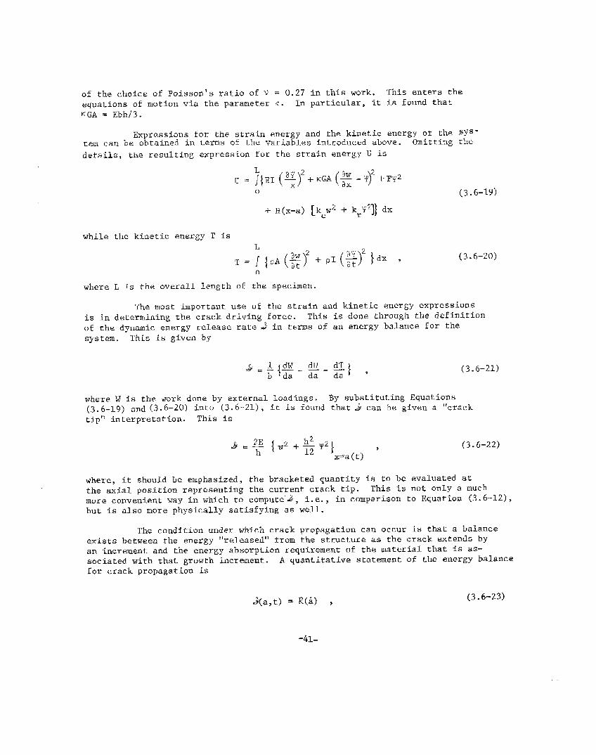
of the choice of Poisson’s ratio of v = 0.27 in Lhis work. This enters theequations of motion via the parameter ~. In particular, Tt is found tharKGA = Ebb/3.
Expressions for the strain energy and the kinetic energy of the sYs-tem can be obtained in t@ms of the variables introduced above. Omitting the
details, the resulting expression for the strain energy u is
u . ~{EI (~)2+KGA(~-Y)2+FY2
o“
-t l~(x-a] ~kew2 + kry2]} dx
while the kinetic energy T is
(3.6-19)
(3.6-20)
o
where L ts the overall leng~h of the specimen.
The most important use of the strain and kinetic energy expressionsis in determining the crack driving force. Thfs is done through rhe definitionof the dynamic energy release rate ~ in terms of an energy balance for thesystem. This is given by
(3.6-21)
where W Is the ~ork done by external loadings. By substi’cutlng Equations(3.6-19) and (3.6-20) into (3.6-21), Ic is found that &“ can be given a “crack
tip” interpretation. This is
(3.6-22)
where, it should be emphasized, the bracketed quantity is to be evaluated atthe axial position representing the current crack tip. This is not only a muchmore convenient way in which to compute”~, i.e., in comparison to Equation (3.6-12),but is also more physically satisfying as well.
The condition under which crack propagation can occur is that a balanceexists between the energy “released” from the structure as the crack extends byan increment and the energy absorption requirement of the material that is as-sociated with that growth increment. A quantitative statement of the energy balancefor crack propagation is
J+(a,t) = R(A) , (3.6-23)
-41-

where the dynamic energy-release rzte (or crack~driving force).# , as can beseen from Equation (3.6-22), is a function of crack-tfp position and time whilethe energy dissipation rate R is a material property that can at most be afunction of crack speed. Note that the units of &and R are energy per unitarea of crack advance.
Figure 3.6.1 illustrates how the dynamic crack-propagation criteriongiven by Equation (3.6-23) is implemented. In Figure 3.6.l(a), the hypotheticalcrack speed is calculated on the basis that, if an increment of crack growthwere to occur at some time following the last previous growth increment, theactual speed would be in inverse proportion to the time. For a specified energy-dissipation rate Rthat is a function of crack speed, the crack tip’s energyrequirement is then known once the hypothetical speed is determined. This isshown as the decreasing curve in Figure 3.6.l(b). A typical computational re-sult for the crack-driving force, as obtained from Equation (3.6-22), is alsoshown. Where these two curves intersect crack growth occurs (i.e., where&=R). Note that this kind of calculation can be perfor~ed for any specifickind of ~ = ~(;)
3.6.2
dependence including the simplest: R = ~ = constant.c
General Approaches to CrackPropagation and Crack Arrest
The arrest of a rapidly propagating crack in a structure under loadcan be considered on several different levels of complexity. Starting fromthe simplest (and least accurate) and continuing with more complicated (butmore accurate) approaches, the various types can be classified as either
o Completely static● Quasi-statice Quasi-dynamic● Fully dynamic.
The primary distinction that differentiates between static and dynamic approachesis thar inertia terms and the contribution of kinetic enery to the crack-drivingforce are excluded in the former but not the latter. Physically, this meansthat static theories are limited to situations where (1) the crack propagatesslowly and (2) changes its speed only gradually. As the extensive work done at
Battelle and other institutions has shown, the arrest of rapid crack propagation
tends to occur rather abruptly. This alone indicates tha~ statically “basedtreatments must be applied to crack arrest with due caution, Quantitative re-sults reinforcing this fdea can be produced too, as shown in the next sectionof this report.
The distinction between the two dynamic analysis procedures lies inthe particular specialization that is involved for simplification. The quasi-dynamic treatments referred to above are those obtained by considering the struc-ture to be an infinite elastic medium. Hence, in these approaches, the effectof stress waves reflected back to the propagating crack tip f~om the boundariesof the structure and/or fromwelded-on stiffners) must bein a fully dynamic analysis,
internal ~oad ~oint~ and discontinuities (e.g.,
neglected. These effects can be taken into accountalbeit at the expense of specializing the structural
-42-

Time Since Last Increment of Crack Extension
(a) Hypothetical crack speed.
I
I
Crack growth occurs.
-—~o
Time Since Last Increment of Crack Extension
(b) Corresponding energies.
FIGURE 3.6.1 GRAPHICAL ILLUSTMTION OFPROPAGATION CRITERION FORMATERIALS
-43-
DYNA!!IC CPACK
SPEED-DEPEhTENT

geometry under consideration (e.g., as in the DCB analysis described above).Nevertheless, in considering crack arrester systems, a fully dynamic analysisprocedure is obviously called for, at least in the preliminary stages of theanalysis.
It is a fact that the arrest point determined from either a static,a quasi-static, and quasi-dynamic treatments will always be closely relatedand, in some cases, will be exactly the same. Consequently, for the purposesof this report, it will suffice to describe the most accurate of these (thequasi-dynamic) with a view towards contrasting its crack arrest predictionswith those of a fully dynamic calculation.
A very elegant analyses of the propag~$i;: ~~ a semi-infinite crackin an infinite medium is that given by Freund. * T Using a Laplace trans-form in conjunction with the Wiener-Hopf Technique, Freund has solved the equa-tions of motion for a half-plane crack propagating in an unbounded medium fora fairly unrestricted class of crack motion. A key result of the analysisrelates the dynamic stress intensity factor K, a function of crack length ajand speed 5, to the product of the static intensity factor K and a universalfunction of crack speed k(~) according to
s
K (a,:) = k(~) Ks(a) .(3.6-24)
The geometry-independent function k, which must be computed numerically, de-creases monotonically from unity at zero crack speed to zero at the Rayleighvelocity CR.
A second key result obtained by Freund is one that relates the dynamicenergy-release rate to the dynamic stress-intensity fac~or. For plane-srrainconditions, this is
(3.6-25)
where A is a geometry independent , monotonically increasing function which isunity at zero speed and becomes unbounded at the Rayleigh speed.
It is of some importance to recognize that Equation (3.6-25), althoughderived for an infinite medium, is gener511y valid, i.e., the relation is geo-
51 As a resulr, it is pos-metry independent. This has been proven by Nilsson.sible to use the idea of dynamic fracture toughnesswith an intrinsic material energy-dissipation rate.
$;t}::)::;~;:b’y
3.6-25), one can write
(3.6-26)
and use either Equation (3.6-24) or the relation
-44-

K(a,~) = K#)
as the crack propagation criterion. In either case, it is foundquasi-dynamic equatfon of motion for the crack t%p is given by
‘k (aK:(a)=— ,
g(a)
(3.6-27)
that the
(3.6-28)
.where g = AKL “1s also a universal function of crack speed. The functiong = g(5) can be interpreted as the ratio of the dynamic to the static energyrelease rates.
In order to apply Equation (3.6-28) to investigate crack arrest, anexplicit relation for the function g(~) is needed. In l?reund’sanalysis, anumerical integration was used to determine this function. However, it can beshown that the function g = g(~) is more than adequately expressed by the sim-ple relation
Hence, substituting Equation (3.6-29) into Equation (3.6-28)resulting equation dimensionless by introducing the materialequation of motion for the crack tip becomes
(3.6-29)
and rendering theconstant K~C, the
(3.6-30)
The next step is to 5ntroduce the relation for K for the DCB specimen. Equation(3.6-30) can then be solved iteratively for the ~rack speed as a function ofcrack length. By numerically integrating these results, the crack length canbe obtained as a funcrion of time.
As a ffnal point, Equation (3.6-30) can be used to show that the crack-arrest point predicted with the quasi-dynamic theory is equivalent to thoseobtained from rhe completely sta~ically based approaches. Consider a materialhaving a dynamic fracture toughness that exhibits a minimum value
is not pr~~~d~~ ‘“~efinite crack speed “ ; nb, the case aM = O and2 ‘~ ~q~~ion (3.6-27) can ~opropagating crack wi 1 arrest when (and only when
longer be satisfied. Using the static theory, this occurs at a crack length arsuch that
Ks(ar) = ~(5M) = l$M .
-45-

NOW, from Equation (3.6-30), this condition means that the track will arrestwhen
[11/2
%K$(ar) = KID(~) 1-~
R
or when
‘S(ar)m%m
where the constant of proportionality is a material property.value of this constant will be simply equal to unity when .% .
in these cases, the arrest point given by either the star~c ordynamic approaches will be exactly the same.
3.6.3 Comparison of Crack Arrest PredictionsMade by Static Fracture Mechanics withThose of Dynamic Fracture Mechanics
Crack propagation experiments in the DCB test specimen can be madefor either of two general kinds of loading conditions: wedge loading andpull-rod loading. For the first set of conditions, crack growth is initiatedfrom a blunt crack by slowly forcing the load pins apart. In this case, es-sentially no external work is done on the specimen as the crack propagates.For the second set of conditions, crack growth is initiated from a sharp crackby pulling the load pins apart with elastic rods. This system does involvework done on the specimen while the crack is running. Either set of conditionscan be analyzed. However, because for a substantial period of time after theinitiation of growth, there is no difference between the two cases, the moreeconomical wedge load conditions have been used in the analyses reported here.
In order to use Equation (3.6-30) to obtain a prediction of crackarrest, the appropriate static stress-intensity factor expression for the geo-metry and load under consideration must be supplied. For the DCB specimenwith wedge lo&ding, Kanninen~6 has shown that
[( Sinh2i.c + sin2).c
)(
Sinhk Cosh 2C– sin?.ccoskK=/3Eh:;.2J ;.{1;il,ipl,c_$in2;c+ ——--— —_—. .—
Sinh22C_ sin2 ],(,.’ )1
[ (--------------Sigh}bcCodlj.c+ sink cos&. 2?.3a3-t6~.2d
Sinh22C– sinzIc )
(3.6-31)
(Sinh2;.r+ sin2lc
)(
SinhlcCosh h – sink cosk -‘+ 6~+0.1:...–.7....–.-.=-.+ ~ -—--——.7––_
hnh2 /.1’ – Sill”/J+c Smh2itic– SIn2k --)1~-46-

where c = L-a is the untracked ligament length, z~ is che pin displacement,and A = 1.565/h.
Aside from the specimen and arrester dimensions and mechanical pro-perties, the test parameter which governs crack propagation in the DCB specfnenunder wedge loading is K the stress-intensity factor acting a~ the time ofcrack--growth initiation.q’Note that because of-the initial blunting of the cracktip, it is possible to have K
> ‘It’ High values of K mean that large amoun~sof energy can be stored in th~ specmnen initially and, flence,rapid crack Pro-pagation can be achieved. Another feature of the wedge-loaded DCB results is
~~at cracks generally propagate at an essentially constant speed. This is use-ful in the analysis of arrester deiices because the speed of the crack as itapproaches the arrester can be readily identified.
Ofieadditional feature makes the wedge-loaded l)CBan even moresuitable device for the preliminary examination of crack arrester devices.This is due to the fact that it is a more efficient supplier of kinetic energyto the crack tip than is an actual strucrure. This makes the predictions madefor a given arrester -system conservative in that lt will under estimate theability of the device to arrest a crack in an actual structure. Looked at inanother way, evaluations of arrester systems using a laboratory test specimenconfiguration such as the DC)3specimen will automatically include a factorof safety.
thesetThe
The particular geometry chosen to perform the computation contrastingdynamic and static crack arrest approaches is shown in Figure 3.612+ An initialof computations was made fox a “standard” specimen without an arrest section.specific dimensions for the geometry shown in Figure 3.6.2 are as follows:*
a =50mm
h0=50mm
e =25mm
b =25mm
I. = 300 mm.
Wedge loading was assumed which means that the pin displacement at the onsetof motion and its minimum displacement thereafter (rib,the pins are free torise above the wedge while the crack is in motion and, fn fact, they do) arefixed by the specified value of K , cf, Equation (3.6-31). A constant crackspeed-independent value of
2wasqtaken ro facill~are comparison with the
static theory in these compu ations. As pointed out above, this then meansthat the arrest point given by the quasi-dynamic theory exactly coincides withthe completely static and quasi-static approaches.
Two example computational results are shown in Figure 3.6.3(a) and(b). These are for K values of 2.0 K and 3.0K1i (G JGm = 4.Oand 9.0),respectively. If canqbe clearly seen ~~at the pre ict$!o$of the crack arrest
* In addition, load pins 100 mm in length and 25 mm in diameter were considered.The specimen material was taken to be steel with E = 0.20865 MN/min2.
-47-

FIGURE 3.6.2. DCB SPECIMEN GEOMETRY FOR ARRESTERCALCULATIONS
154
[
B. mmsY!!u—
0 0
t
a125 A :5
Solid Domts denoteO*
#
Fv% 20 40 60 00 IC9 120
t ● Time Since lnit, alien 01 CmCk Gmwfh [~secl
FIGURE 3.6.3.(a). CRACK PROPAGATIONCOMPUTATIONS FOR A DCB SPECIMEN WITHAN INTEKMITTANTLY ATTACHED STIFFEN-ER CRACK ARRESTER FOR K /K = 2.0q Ic
#r
/
,“,’
.’,’
Ku/K ~ = 3,o ,“
,-
J,.
J$
.fully dynomc •aua,ion~
(3.3-15. 16)
#
&
so - Crock arrest ($fo,i~) /
Quast-dynomc Solut,on
Couatlon (3,3-3,5)
?00 20 *W no IM 120 ,-
I - Tim. From lnltlatlon cf Gmwm (pstc}
FIGURE 3.6.3.(b). CO&fl?ARISONOF CR4CKPROPAGATION PREI)ICTICNS FROM FULLYDYNAMIC ANALYSIS WITH QUASI-DYNAMICANALYSIS FOR A STANDARD DCB SPECIMENWITH ~ = KIC
-48-

point is a very considerable underestimate--the fully dynamic theory alwayspredicts that the crack would propagate well beyond the crack arrest pointdetermined by a static approach. In fact, the static theory would always pre-dict crack arrest within the DCB specimen under wedge loading conditions.Tlfiscan be seen from Equation (3.6-31) which shows that K+O as a+L. However,
many experiments in which the crack completely penetrates the specimen withoutarresting under wedge loading conditions have been performed. ~l~isfactfurther distinguishes between the static and the fully dynamic analysis pro-cedures. The latter does not suffer from this limitation, as can be seen inthe computation shown in Figure 3.6.3(b) where the crack did not arrest.
The comparative arrest point predictions made with the fully dynamicand the static approaches for the standard DCB test specimen are summarizedin Figure 3.6.4. It is again clear that the static theory gives a possiblydangerous overestimate of the capaciry of a structure to arrest a crack. Thisreemphasizes the conclusion stated above that the investigation of systems de-signed to arrest a rapidly propagating crack must be conducted within the frame-work of a fully dynamic crack-propagation theory.
The physical reason for the inadequacy of the static and quasi-dynamicapproaches to predicting crack arrest can be seen in Figure 3.6.5. This figureshows the distribution of the energy contained in the test specimen during therun-arrest process for the calculation shown in Figure 3.6.3(a). Because noexternal work is supplied to the specimen with wedge-loading conditions, as thefracture energy is removed (at a constant rate due to the assumption that
~ = KIC) , the total energy to be partitioned into strain energy and kinetic
energy steadily diminishes. It can be seen that while the strain energygenerally decreases (as in the static situation), the kinetic energy initiallyincreases, reaches a maximum, then decreases almost to zero.
Comparison with the results shown in Figure 3.6.3(a) reveals that thestatically calculated arrest point is reached at about the same point that thekinetic energy reaches a maximum in the fully dynamic calculation. This indicatesthat it is the return of kinetic energy to the crack tip that is the ;rimarysource of difference between the static and fully dynamic approaches. Theaverage rate of change of the kinetic energy being greater (negatively) than thestrain energy after the maximum has been reached further reveals that rhe kineticenergy actually provides the greater contribution to the crack driving force,cf, Equation (3.6-21).
The practical conclusion thar can be drawn from these calculationsis the following. When a crack arrester system is to be used in a ship hull orany other engineering structure, the dynam<.camplifica~ion of the crack drivingforce is an important consideration in the design. This increase is primarilydue to the return of kinetic energy to the crack tip and, in turn, this is afunction of the geometry of the structure. One practical way of accounting forthis effect that could be used in the engineering design process is by theconcept of a “dynamic amplification factor”, a multiplicative geometry-dependentfactor which could be incorporated into an otherwise completely static fracture-mechanic analysis.
* The dynamic and static strain energies will also contribute to a difference butthis is apparently less important.
“4k9-

PPmdicved ty fully
dynamti onolys is.
Equations (3.3 -15, 16)
Predicted by stohcurmlwis, Equahon (3.3-3o)
O.cI.c 2.0 3.0
xq/K1cFIGURE 3.6.4. COMPARISON OF CRMK
ARREST POINT IN A DCB TEST SPECIMENWITH sTATIC AND WITH FULLY DYNAMICANALYSIS
Ou 1 ! Lo 25 50 75 100 125
a-~ . Crock Pro?agotion D#stance [mm]
FIGURE 3.6.j. DISTRIBUTION OF ENERGYDURING RAPID CRACK PROPAGATION INA DCB TEST SPECIMEN FOR Kq/K1c = 2.0
‘m ‘D = ‘IC
Very large monolithic structures will return no kinetic energy and,hence, will”have a dynamic amplification factor of unity. The DCB test speci-men 5s a highly efficient utilizer of kinetic energy and, consequently, willhave a relatively high dynamic amplification factor, e.g., approximately two.A structure li~e a ship hull might be expected co have a value close to unity,but this cannot be established without further work. It might be anticipatedthat the manner in which the arrester is attached to the base plate may havea large effect on the dynamfc amplification factor, perhaps as much as thestructural configuration itself.
Finally, for comparison with the calculations reported in Section 6,the results given in Figures 3.6.6 and 3.6.7 are of interest. In Figure3.6.6 are shown the average crack speeds calculated for crack propagation inthe standard DCB specimen without arrester as a function of che stress-inten-sity factor at the initiation of crack growth. [The difference between theaverage speed during the inirial phase”of growth and the average speed overthe entire event can best be seen in Figure 3.6.3(b)]. These can be viewedas input to the problem found by the designer of a crack arrester system.The results shown in Figure 3.6.7 typify the kind of information that isavailable to him in doing his job, albeit for a wedge-loaded DCB specimen.That is, given an anticipated crack speed or, equivalently, a K value, Figure3.6.7 provides an obvLous way of estimating the toughness requi~ed of an inte-gral “liigh-toughness” strip crack arrester using a static approach. Some ex-
ample calculations showing how this process would be performed, together withfurther illustrations illustrating the over optimism of the results given inFigure 3.6.7, are given in Section 6 of this report.
-50-
—. ...
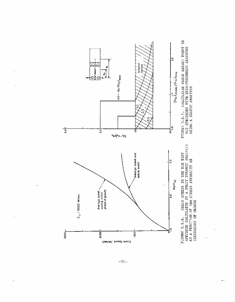
,,0*
1 00 0 0
~-
,,
Ue
-51-
zH
4.0 FATIGUE-CRACK PROPAGATION
4.1 INTRODUCTION
This section Is concerned with fatigue-crack growth in ship “hullsand with the effect of crack arresters on crack growth. In order to facilitatethe discussion, the concepts of crack-growth analysis and stress-history effectswill be briefly discussed first. Thereafter, the procedure for analysis of ser-vice cracks will be considered. Finally, fail-safe design practice and arresterefficiency will be discussed.
Fatigue-crack-growth analysis of damage-tolerant structures has todeal with both prearrest and postarrest behavior. In the prearrest period,the crack may grow from a small initial flaw to a size that causes fast un-stable crack propagation. This period is of interest if attempts are made toprevent cracks from reaching a critical size by means of periodic inspections.If unstable crack growth and arrest occurs, the postarrest behavior is ofinterest. The long arrested crack will extend by subsequent cyclic loads.It should not grow to a size that would again cause fast fracture during a re-latively short postarrest period required to complete the voyage and dockthe ship for repair of the arrested partial failure. Both prearrest and post-arrest crack growth will be considered in this section.
4.2 CONCEPTS OF CRACK GROWTH ANALYSIS
The concept of crack-growth analysis is now well known. Its appli-cation to ship strur.tureshas been the subject of a recent study of the ShipStructure Committee 70 . Therefore, the basic concept will be discussed onlybriefly here.
Fatigue-crack growth is governed by the range of the stress-intensityfactor (AK) during a cycle. Generally, the rate of crack propagation can beexpressed as
da—= f(AK,R) ,dN
(4.2-1)
where a is the crack size, N is the cycle number, and R is the ratio betweenthe minimum and maximum stress in a cycle. Many forms have been proposed 71*72973
for Equation (4.2-1). For the purpose of the present discussion, it is sufficientto use the simple relationship
da= ~/@YdN
-52-
(4.2-2)

71which is applicable to many steels for a limited range of AK, with n on theorder of 3, and R = O (i.e., the minimum stress in each cycle is zero).
The crack-growth properties of a ma~erial can be determined “byusinga simple specimen for which a K-solution is known. Center-cracked specimensare often used, for which
if the crack isis the range of
small compared to the specimenthe nominal stress in a cycle.
72size. In
The specimen
(4.2-3)
this equation, Aris subjected to
cyclic loading and crack growth is recorded. The increment of crack growthper cycle pro~ides-the cr~clc.growth rare da/dN which can then be plot~ed asa function of AK. According to Equation (4.2-2), the result will be a straightltne on double-log paper.
The prediction of cxack growth in a structure then requires a cal-culation of the stress-intensity factor for the given structural geometry witha crack at the critical location. Using thfs stress intens<ty, the crack-growth rate can be determined from the da/dN-AK plot. An integration over arange of crack sizes provides the crack-growth curve, i.e. , crack size as afunction of the number of cycles.
4.3 STRESS-HISTORY EFFECTS
The analysis of the growth of service cracks is complicated by aber of factors. The most prominent of these is the service stress historyShip hull stresses vary randomly as a function of payload distribution and
num=
weather. For a crack-growth analysis, the service load history may be describedby Tts root mean squares (rms) value, i~s power spectrum, or its excedancespectrum.
If crack-growth calculations have to be based on the rms value, random-load crack-grow~h data have to be available. This is usually not the case. Ifthe analysis is based on the spectrum, some stress his~ory has to be assumed andthe crack-growth integration as described in the previous section is to be basedon the stresses in the assumed history. Computer routines for such an analysisare available, especially in the aerospace industry.
In some materials, the occurrence of high-stress cycles has a drasticeffect on crack growth during subsequent cycling at lower amplitudes 74,75,76
During a high-s~ress cycle, a relatively large plastic zone develops at thecrack tip. Due to its permanent stretch, the material in this zone does notfit normally in its elastic surrounds after unloading. As a result, it willbe under a compressive residual stress. This means that the general stresslevel at the crack tip region is lowered, so that subsequent crack growth isslowed down. This effect is called retardation. It is illustrated in Figure(4.3.1).
-53-

—.— ——— —w————.——40--
I
30 – I
E I
0- 20 - IN IGs /vo I
G 10 - /
/8 – applications
6 – /
4 [1,105 2.105 3.105 4.105 5.105
Cycles ——+
FIGURE 4.3.1. RETARDATION OF FATIGUE CRACKGROWTH DUE TO OVERLOADS
-54-

Models have been developed71,14
to account for the retardation be-
havior in the crack-growth integration procedure. At Present, no information isavailable on whether retardation is a significant factor in ship steels sub-jected to a ship-stress spectrum. Therefore, a crack-growth an~lysis wouldconservatively neglect retardation. However, it is worth exploring whether the
beneficial effect of retardation can be counted on in ship hull cracking. Sinceretardation IS usually more pronounced in higher strength materials. it wouldbecome of special importance for modern high-strength ship steels.
4.4 ANALYSIS OF SERVICE CRACKS
The prediction of crack growth in service requires the followingsteps:
●
●
●
●
●
Analysi’s of the structure and structural details to definecritical locations
Stress analysis of the structural details to determine thastress-intensity factor for a crack at the critical location
Establishment of service stress history at the locationof the crack
Determination of material crack-growth properties, takinginto account the different crack-growth rates in weldmaterial and heat-affected zone if relevant to the crackproblem under consideration
Integration of crack growth, either cycle-by-cycle, orbloc~s of cycles for a small increment of crack growth.
Each of these steps was discussed in some detail in the previous para-graphs. Only the stress analysis to arrive at the stress-intensity solutionwill be briefly considered in the following paragraphs.
A reliable stress-intensity solution is even more important forfatigue analysis than for residual strength analysis, because fatigue-crack-growth rates vary with the third or fourth power of AK. Not only nominalstresses are of importance, but also local stresses due to stress concentrationsand residual stresses.
The nominal stress can be obtained from a global-stress analysis orfinite-element analysis. These can be applied to a finite-element analysisof a structural detail containing the crack to include local stress concentra-tions, e.g., in weld fillets and cutouts. Although techniques exist to in-clude residual stresses, the complexity of the problem may make a detailedanalysis prohibitive. (Residual stresses at the crack tip due to high-stresscycles would be automatically accounted for in the crack-growth integrationprocedures if a retardation model’is used.)
-55-
Proper modeling of structural details is more important if the criticalcrack size is small. In that case, most of the useful crack-growth life is spentwhile the crack is still influenced by the stress concentration at its initia-tion site. Careful detail design will be aimed at reducing stress concentrations .This has the advantage that (1) the growth of small cracks will be slower and(2) the critical crack size will be larger. It implies tha~ a significant partof the useful crack-growth life is spent while the crack tip is well away fromthe initial stress raiser.
From the point of view of safety, large critical crack sizes arepreferable because there is a better chance of timely crack detection. Inthat case, the time spent in the small crack region is of less interest.Since only the growth of relatively large cracks has to be considered, themodeling of the initial stress raiser and of the residual stresses becomeless critical.
4.5 FAIL-SAFE CONCEPTS
Safety requires that a structure can still withstand anappreciable load under the presence of cracks or failed parts. It also re-quires that
● Either the damage can be detected before it reaches adangerous size
● Or that damage growth is so slow that it never reachesa dangerous size through the specified life
● Or the structure is provided with means to arrest acrack when the damage has reached the critical size thatcauses unstable growth. Sufficient remaining crack-growth life should then provide some time for correctiveaction.
In each case, fatigue-crack growth is of importance. Considerthe crack-growth curve in Figure 4.5.1. Suppose the structure contains aninitial defect of the size a. . If the crack were not to grow critical withina lifetime, the maximum life~of the structure would be t . In order to cal-culate this life, the growth of small cracks would have k. be consideredinvolving the difficulties discussed in the previous section.
*If the inital defect size happended to be a instead of a, (Figure
4.5.1), the life to critical would be much shorter. In view of this~risk, alarge safety factor would have to be taken on tL, or, more realistically, onecan provide for crack arresters that would limit the risk of a critical crack.
Stretching this idea further, one might entirely rely upon crackarresters and not be concerned about the point in time they might become ef-fective. However, an unstable crack might still cause considerable damage.It would be advantageous if a crack could be detected and repaired before itgrows to a critical size. This would require
-56-
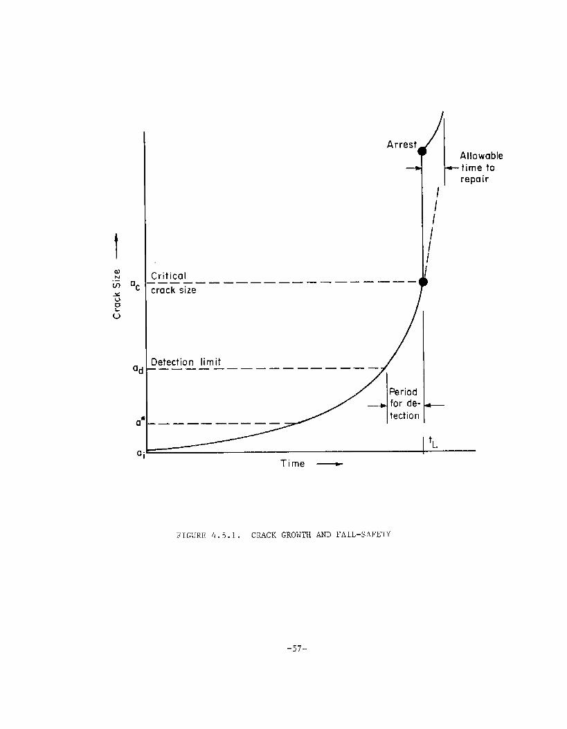
Iac
al
a
c
Arresti
Critical.—— — ——— ——— —— — —— —— —— —1crack size
Detection limit-—— ——— —— ——— ——— ——— /
/’////
1I
Allowable-time to
repair
/’4 Periodfor de-
tection-—— —— ——. ——
I ‘L
FIGURE 4.5.1. CRACK GROWTH AND “FAIL-SAl?E~
-57-

● Periodic inspection which may not always be feasible
● Easily detectable cracks; i.e., large critical crack sizeand a long period for detection
● Scheduling of inspections on the basis-of a calculatedcrack-growth curve in the region a
dto ac (Figure L.5.1).
If the critical crack size is large and crack growth is slow, thedetecrion limit a may be rather large. This would imply that inspection re-quirements could te less stringent. Also, crack-growth calculations wouldbe less difficult because cracks in the range ad-at would be large enoughnot to be affected too much anymore by the stress concentration at the initia-tion site.
In the case fast crack growth and arrest do occur the rate of crackgrowrh after arrest is of interest for the safety during the rest of the voy-age until docking for repair. Since a postarrest crack will be large, fatigue-crack-growrh rates may be high. This asks for rather accurace information onpostarrest behavior.
In order to obtain an appreciation of the time involved in crackpropagation, a simple and rough estimate was made of a crack-growt”h curve fora ship hull. A through crack in a deck is assumed at a locatlon not directlyaffected by other structural members. Two stress spectra were considered,10one for the Wolverine State and the other for the Minnesota . Figure4.5.2 shows the spectra together with rhe srepped approximation used for the
.-,—. .........—.
crack-growth analysis.
Since reliable crack-growth data for ship steel were not available,the da/dN -AK relation was assumed as in Figure 4.5.3. The spectrum was dividedin blocks of 0.1 year and crack growth was calculated for 0.2–inch crack incre–ments for the small crack region and l-inch increments for the large crackregion. No retardation was considered. The results are shown in Figure 4.5.4.
It turned out that crack growth was largely determined by the low-stress cycles. This is the reason why crack growth for the Minnesota—— --—-..spectrum is slower than for the Wolverine State spectrum, since the latter con-tains many more low-amplitude cycles.
Atypical value for the toughness at low temperature would be860 ksi v%. Taking 20 psi as the highest stress in the spectrum, the criticalcrack size wofildbe 2a = 2.6021R.202-= 5.7 in. If the detectable crack sizewere 3 inches, the period for crack detection would be 3 years for the Min-nesota and 0.5 years for the Wolverine State’ .—. These times are long enoughto conclude that a fail–safe approa-ch”base~”on crack growth may be feasible.
DespiLe tbe increasingamount ~f literature on crack arresters Tn ship
hulls, no information was available on the interaction of fatigue cracks with
-58-

lo-~-
20-
15-
10- 164-
5- “Wolverine State”
o,o. .I234S S70 ●
16$ -
25- =
:*
20 g 16●-
15- z-U~
10-
s- t4inne50ta Ii 7-
0 1,.01:s45 67@*
EXCEEDANCE SPECTRA10“m-
FOR 20 YEARS
FIGURE 4.5.2. STRESSFOR TWO SHIPS, EACHEXPERIENCE
FIGURE 4.5.3. ASSUMED CRACK RATEPROPERTIES FOR CRACK-GROWTH CURVESIN FIGURE 4.5.2
“Wolverine State” /spectrum
/
I00
! I [1 z 3
Years—
FIGURE 4.5.4, HYPOTHETICAL CRACK GROWTH CURVESCALCULATED IN THE BASIS OF IWO SHIP SPECTM
-59-
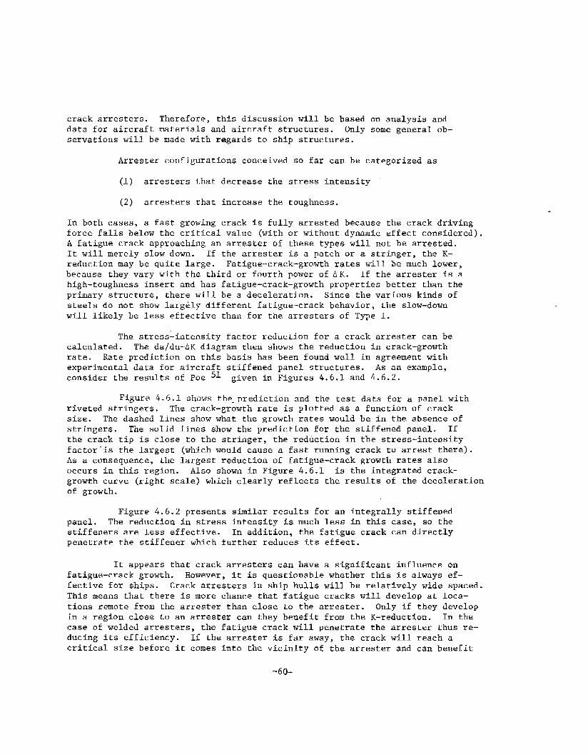
crack arresters. Therefore, this discussion will be based on analysis anddata for aircraft materials and aircraft structures. Only some general ob-servations will be made with regards to ship structures.
Arrester configurations conceived so far can be categorized as
(1) arresters that decrease the stress intensity
(2) arresters that increase the toughness.
In both cases, a fast growing crack is fully arrested because the crack-drivingforce falls below the critical value (with or without dynamic effect considered).A farigue crack approaching an arrester of these types will not be arrested.It will merely slow down. If the arrester is a patch or a stringer, the K-reduction may be quite large. Fatigue-crack-growth rates will be much lower,because they vary with the third or fourth power of AK. If the arrester is ahigh-toughness insert and has fatigue-crack–growth properties better than theprimary structure, there will be a deceleration. Since the various kinds ofsteels do not show largdy different fatigue-crack behavior, the slow-downwill likely be less eftective than for the arresters of Type 1.
The stress-intensity factor reduction for a crack arrester can becalculated. The da/dn-AK diagram then shows the reduccion in crack-growthrate. Rate prediction on this basis has been found well in agreement withexperimental data for aircraft stiffened panel structures. As an example,consider the results of Poe 51 given in Figures 4.6.1 and 4.6.2.
Figure 4.6.1 shows the_prediction and the test data for a panel withriveted stringers. The crack-growth rate is plotted as a function of cracksize. The dashed lines show what the growtl~rates would be in the absence ofstringers. The solid lines show the prediction for the stiffened panel. Ifthe crack tip is close to the stringer, the reduction in the stress-intens%tyfactor”is the largest (which would cause a fast running crack to arrest there).As a consequence, the largest reduction of fatigue-crack growth rates alsooccurs in this region. Also shown in Figure 4.6.1 is the integrated crack-growth curve (right scale) which clearly reflects the results of the decelerationof growth.
Figure 4.6.2 presents similar results for an integrally stiffenedpanel. The reduction in stress intensity is much less in this case, so thestiffeners are less effective. In addition, the fatigue crack can directlypenetrate the stiffener which further reduces its effect.
It appears that crack arresters can have a significant influence onfatigue-crack growth. However, it is questionable whether this is always ef-fective for ships. Crack arresters in ship hulls will be relatively wide spaced.This means that there is more chance that fatigue cracks will develop at loca-tions remote from the arrester than close to the arrester. Only if they developin a region close to an arrester can they benefit from the K-reduction. In thecase of welded arresters, the fatigue crack will penetrate the arrester thus re-ducing its efficiency. If the arrester is far away, the crack will reach acritical sfze before it comes into the vicinity of the arrester and can benefit
-60-
5—. —. zu—
I—.
R
0
‘- .-=
‘o
EEu-
‘o
~@3/’u! ‘Np/Dp
CJ o 0 0 ; o 0r- W In rn w g
I I I 1 I I I
0+
om
o E-t-lo
0.
00
I/l
0’ I I 1 ——
*10
N ?-l m w‘g ‘g ‘Q ‘g ‘g
Ii.-0-
from the K-reduction. In the case of welded arresters, the fatigue crack willpenetrate the arrester thus reducing its efficiency. If the arrester is faraway, the crack will reach a critical size before it comes into the vicinity ofthe arrester and can benefit from it. h the example in the prevfous section,the critical crack size was on the order of 6 inches.
The significance of arresters for fatfgue-crack growth is mostlikely in the postarrest behavior. After instability and arrest, the arrestermay be effective to sufficiently decrease growth rates to allow completion ofthe voyage until repair. In that case, the tough material insert will notlargely reduce fatigue-crack-propagation rates. However, in the case of rivetedarrester strips the postarrest fatigue crack would fully benefit from the growthrate reductions shown in Figure 4.6.1.
As pointed out In Section 3.5, the reduction of the stresses in thehull would occur ac the expense of high stresses in the arrester strip. Thesestresses may be so high that the arrester strip has only a very short fatiguelife. If it would fail by fatigue, it would cause immediate fast fracture ofthe hull, because it would no longer act as an arrester. Therefore, a completeanalysis of postarrest behavior should include fatigue analysis of the arrestersCrip. It is recommended that complete prearrest and postarrest analyses be madeof some realistic structures with arresters, to obtain definitive informationof these matters and to evaluate the feasibility of arrester systems from thepoint of view of fatigue’and fatigue-crack propagation.
-62-

5.0 CHARACTERIZATION Ol?ARRESTER MATERIALS
The design of in-plane, energy–absorbing arresters, specifically--
the selection of optimum arrester width, thickness, spacing and materialcombinations--requires the measurement of the fracture energy or toughnessvalues of candidate materials. In this section, estimates are made of theminimum toughness levels required of steels for this class of arrester.Generally, the toughness levels are found to be high, and at or near theupper shelf. Some of the problems associated with measuring large fracturetoughness values are described, along with possible ways to overcome ‘these
~~”~~~~- ~he arrestertoughness requirements recommended by Rolfe,
3 xn terms of dynamic tear (DTE) energy are compared with esti-mated minimum
%requirements. Finally, currently available toughness
data for ship s eels are compared with estimated requirements for arresters.
5.1 ESTIWTE OF 1$ (OR KC) FOR ARRESTER MATERIALS
It is instructive to make a rough estimate of the toughnesslevels that are required of in-plane arresters. Thts is most easily donefor the case of a plate that is large relative to a propagating centrallylocated crack bounded by two arresters of the same thickness as the baseplate, as shown in Figure 5.1.1. The calculation can presently be madeonly for assumed values of T, the fraction of the kinetic energy impartedto the structure that is returned to the crack tip prior to arrest. liowever,~r:dies$~~al, finite difference dynamic analyses have recently been
and could be used In the future to evaluate and solve morecomplex problems.
Combinations of the minimum values of fracture energy Rfracture toughness < F’~m, and the width W of the arrester plate w lch willstop the largestby the following
cra&n~ccommodated by the arrester spacing 2S are givenexpressions which are derived in Appendix A.
w= Sa
R .@@AP,tninimum E
KD,minimum
‘g@ (1
(1 +V-@)
+,@)1/2
(5.1)
(5.2}
(5.3)
-63-
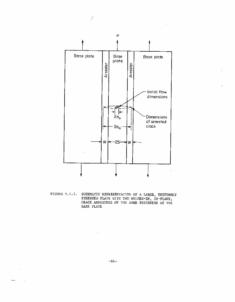
1’”
) i
Base p10
T
u
1Baseplate
-A.——.
-IF2 aO
–2aa–
—2s—
T
t
Base plate
\ Dimensionsof arrestedcrack
.
I
FIGURE 5.1.1. SCHEMATIC REPRESENTATION OF A LARGE, UNIFORMLYSTRESSED PLATE WITH TWO WELDED-IN, IN-PLANE,CRACK ARRESTERS OF THE SAME THICKNESS AS THEBASE PLATE
-64-
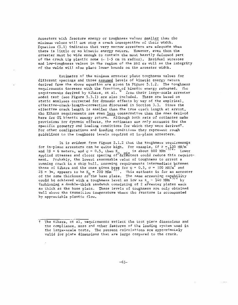
Arresters with fracture energy or toughness values smaller than theminimum values will not stop a crack irrespective of their width.Equation (5.1) indicates that very narrow arresters are adequate whenthere is little or no kinetic energy return. However, even then thearrester must be wide enough to contafn the most heavily deformed partof the crack tip plastic zone (- 1-5 cm in radius). Residual stressesand low-toughness values in the region of the HAZ as well as the integrityof the welds will also place lower bounds on the arrester width.
Estimates of the minimum arrester plate toughness values fordifferent spacings and three assumed levels of kinetic energy returnderived from the above equation are given in Figure 5.1.2. The toughnessrequirements increase with the fraction of kinetic energy returned.
6The
requirements derived by Kihara, et al. from their large-scale arrestermodel test (see Figure 5.3.1) are also included. These are based onstatic analyses corrected for dynamic effects “byway of the empirical,effective-crack-length-correction discussed in Section 3.3. Since theeffective crack length is smaller than the true crack length a~ arrest,the Kihara requirements are even less conservative than the ones derivedhere for OX kinetic energy return. Although “bothsets of estimates makeprovisions for dynamic effects, the estimates are only accurate for thespecific geometry and loading conditions for which they were derived?.For other configurations and loading conditions they represent roughguidelines to the toughness levels required of in-plane arresters.
It is evident from Figure 5.1.2 that the toughness requirement s5for in-plane arresters can be quite high. For example, if 0 = O MN/m
-3?2.and 2S = 6 meters, and y = 0.5, then
% minis about 600 MNIII Lower
applied stresses and closer spacing of Arresters could reduce this require-ment. Probably, the lowest reasonable value of toughness to arrest arunning crack in a ship hull, assuming requirements intermediate ~etweenthose of Kihara and the ones given h2S = 3m, appears to be ~ .200 ~m.?~!? ‘or T = o.?, u = 100 ~/m and
. This estimate is for an arresterof the same thickness as the base plate. The same arresting cap~~~litYcould be achieved with a toughness level as low as ~=140~m byfashioning a double-thick sandwich consisting of 2 arrester plates eachas thick as the base plate. These levels of toughness are only obtainedwell above the transition temperature where the fracture is accompaniedby appreciable plastic flow.
t The Kihara, et al, requirements reflect the test piece dimensions andthe compliance, mass and other features of the loading system used inthe large-scale tests. The present calculations are approximatelyvalid for plate dimensions that are large compared to the crack.
-65-

Q 120m
‘Ez2
100’
80(
:.
: 60(.
X“
40(
20C
o
Le.-.—1000-
800 -
600-
400-
200-
2S= 10m
/+ =0.5
/2S z6m
//”cp=o.5
//1.+=,+’0.5
2s
/’”
+=~
~~2S=6m]
~’/////’
/0’//
// ---’//
//./
o0 10 20 30 40
2S=3m 1
ksi
‘ 3m
w vs Kc
from Kihora,etal 6
1 I
o 501
100 I50 200 250 300 MN/m~Gross Tensile Stress, m
FIGURE 5.1.2. ESTIMATED MINIMUM KD REQUIREMENTS FOR ARRESTER STEELS BASED ONEQUATION (5.3)
-66-

Figure 5.1.2 also reveals the consequences of employing higherstrength steels in ship construction. If the yield strength of the steel
is doubled, it is likely that both the operating stresses and the minimum~ requirement will be doubled for a particular arre~ter spacing. Whereas
for ordinary strength arrester steels (ov = 275 MN/m ) KD ~tiilsho~~dbe
about 200-400 MN-3/2
the requirement for higher stren t< steels (Oy = 550?to 700 MN/m2) should ~e a“KD min about 400 to 1000 MNm- /2. These high-
toughness values are difficult to realize in practice because of the generaltrend toward decreasing upper shelf toughness with increasing yield strengthlevels . As noted above, a multiple thickness sandwich of a,rresterplatescan raise the crack stopping capabilities of arresting devices in thesecases.
5.2 MEASURING ~ VALUES OF TOUGH-ARRESTER STEELS
From considerations described in Section 5.1 it appears thatthe minim~m required ~ values for arrester steels of ordinary s.~~$ngth(275 MN/m yield strength) are in the range from 200 to 400 MNmdepending on arrester spacing and service stresses. ,Doubling of th~ yieldstrength (and the service stresses) will double these minimum ~ require-ments.
Certain problems exist in the measurement of such high levelsof fracture toughness. The most highly developed methods for measuringfracture toughness ar~ applicable to fractures in whfch plasticity islimited--for example, fractures that occur under plane-strain conditionsor under plane-stress conditions in which the p“lastic zone size is smallrelative to specimen dimensions and crack length (see ASTM-E-399-74).Because of the limited plasticity, these fractures can be analyzed bythe methods of linear elastic fracture mechanics (LEFM) to obtain plane-strain fracture-toughness parameters such as K , K , K , andtheir plane-stress counterparts with the I rem%ed ~~om ~~ea~~b~&ipt.The limited fracture plasticity that is necessary for successful applica-tionof LEFM methods is the very antithesis of the desired behavior ofarrester steels, where large plastic zones and significant shear lipsare essential to proper performance. Accordingly, problems arise inattempting to use LEl?Mmethods for measuring fracture-toughness parametersof tough materials.
In the following paragraphs, several methods for measuring orapproximating ~ values for tough steels by the methods of fracturemechanics are described.
5.2.1 Approximating 1~ Values with K K or .1,c’ Ic’
Measurements
As noted in Section 3.2,% in
may coincide with K (the KC-
va~ue at zero velocity) for tough ste~Ts since these fiacturecwith the
–67-

fibrous mode. In this case, static measurements of Kc can serve as aconservative estimate ofthe plane-strain K
~. The Kc-values can, in turn, be related to
Ic:
Kc = CIKIC (5.4)
34,35,36where 1 < C <2as a lower ~ound measure”of
This means that K -values could also serve
2or as away o$cestimating K provided Lhe
factor Cl, is known. In prac ice, the plate size and thicfcnss xequire-Ec >
ments for measuring Kc and K values for materials with v 0.26/2
are pro~$bi~ive. .~;;OeEP3921$Or a steel with a yield S~re@~h D1 :de275 MTlm and K , the width of a center-cracked pane -quate to measur~ K is about 3rn,and the th~ckness required to measure KIC
is about 1 m. Mor~ recent J techniques offer the possibility of reducing
the thickness requirement bylacnorder Of magnitude. 78’ Consequently,
JIc
measurements may offer one practical route to the evaluation of%
or R values of high-toughness ship plate for arresters.
5.2.2 ,Approximating ~ From Crack-Opening Disp~acemenC
Robinson and Tetelman 7’ have shown that K cam be calculatedfrom measurement of the crack-tip opening displacement~c(COD) at the onset
of unstable fracture in relatively small specimens, using the followingrelationship:
u “E’COD1/2
K= + (5.5)Ic l-v
Methods for measuring COD are described in British Standards DD19:1972.Use of such COD techniques would then permitway of Equation (5.4).
~ to be approximated by
The possibility exists also of applying COD methods to dynamictests. Here, actual COD measurements are difficult but Robinson and
Tetelman have shown that COD values can be approximated reasonably wellfrom measurement of notch-root-contraction (NRC) on the fractured testpiece.
-68-

5.2.3
Athe ability
Direct Measurement of KID or I> With Batrelle DtiDIex
Double-Cantilever-Beam Test
test has been developed at Battelle specifically to measureof various steels to arrest a rapidly pxopaga~ing fracture.
By making appropriate measurements during the tes~ and by applying adynamic analysis to the results, the LEFM parameters KID or I% can beobtained directly from the test. To date, the test has employed a
relatively small test piece to measure K values for steels 01 moderate
toughness. The test piece is basically &Ddouble-cantilever-bearn (DCE)specimen that has been modifted by a~taching a high-strength/low*toughness,Istarter~ectionf to the “test section“ by means of an electron beam weld.It is further modified by introducing face-grooves along the fracturepath. This arrangement, pictured in Figure 5.2.1 and referred to as 2duplex DCB specimen, makes it possible to initiate a rapidly propagatf~gcrack at virtually any temperature, even above the ~rami~fon ~emperatureof the test plate. When the propagating crack penetrates the zest.Sectfon, energy is absorbed fn the fraCCUre process. If th$ test sec~ion
has sufficient toughness, the crack will eventually arrest. Analysis ofthe data by the methods described in Section 3.3 permits calculation ofKID“
There are several reasons why valid K dzta can be obtzineeXg
from relatively small duplex DCB specimens of mo erately toug,hsteels.
First, the high-strength/low-toughness starter section reduces the plane-strain thickness requirements drastically. Second, the grooves along
the fracture path develop constraints similar to these associated withincreased plate thickness. Thirdj the propaga~ing czzck prcduces avery high strain rate at the crack tip, which causes the etfectivcyield s~rength to be raised (perhaps twice the static yield strength)and the plastic zone size to be reduced.
Figure 5.5.2 shows measured values of K:1)
obkained from
duplex DCB specimens for several grades of ship s eel tested near thenilductility temperature. The behavior of these steels is i~terestingfrom several standpoints. The toughness of each of the four steels isseen to be strongly dependent on crack velocity, being greatest atsmall velocities. Nonetheless, KID for a propagating crack exceeds
K, the energy associated with cracltinitiation by impact. There iss~$e thought that the minimum in the K versus-velocity curve (ifa minimum exists) may approxima~e the ~~ values but tb.isremains cobe demonstrated.
In principle, the duplex DCB test can be used also ‘CO obtain
valid ~databy eliminating the side grooves. ~iowever, For,tespecimen dimensions currently employed to measure K , removal of che
side grooves would introduce several problems, part$~ularly for high-toughness steels. The amount of strain energy that can be stored fnthe arms of the test piece is LOL sufficient to drive the crack into
-69_
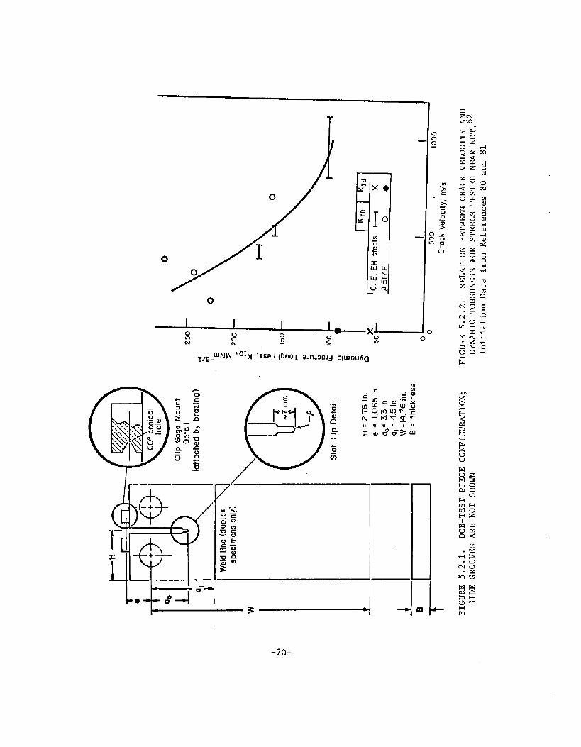
0
.
II !1 II It II II
xwOOO-3m
x
.—
u
u

the tough test section for any appreciable distance, thus makinganalysis of the results difficult. With existing specimen dimensionsand procedures, ~~~,estimated upper limit of toughness measurementsis about 250 MNm . Also, the plastic zone radius may approach or
exceed the arm height of the specimen. Finally, cracks propagating intothe tough test section frequently branch in the absence of side grooves;this also makes analysis of the results difficult.
~he Battelle duplex DCB test is well-suited to the study ofarrester behavior, both because the test section is struck with a fast-moving crack and because the test has been the subject of extensivedymamic analysis (see Section 3.0). It will require two major modifica-tions, however, if it is to be used for measuring ~ of very tougharrester steels. First, its fracture-toughness capacity must 12~,~n-creased substantially above the present limit of about 25~ MNm .
This may require increasing the specimen size to permit storage ofgreater quantities of energy in the arms. Second, the tendency ofthe crack to branch must be overcome. It is believed that this canbe accomplished by machine loading (in place of wedge loading) incombination with a modified grip design.
5.3 CORRELATION OF LEFM PARMIETERS wrm DYNAMIC TEAR ENERGY (DTE)
Another avenue for evaluating large fracture-toughness valuesis to measure the total energy absorbed in the fracture of a notchedbend specimen in the dynamic tear (DT) test. The energy to fracture thespecimen is provided by a pendulum whose velocity just prior to impactis approximately 5 to 10 m/s. The total energy absorbed in the processof breaking the specimen, termed the dynamic tear energy (DTE), is ob-served directly by noting the height of the pendulum swing after fracture.The DTE divided by A, the cross-sectional area of the test piece, is ameasure of the fracture energy, R
R=l DTE.—8A
(5.6)
where ~ = 1 when the energy losses in the impact test remote from thecrack tip are zero and ~> 1 when significant energy losses occur. Thecorresponding fracture toughness, ~ can be expressed as
orflKD2A
DTE =E
(5.7)
(5.8)
-71-
.

Figure 5.3.lshows the relationship between DTE and KD as expressed in Equation(5.8) for ~-values of 1 and 3. Also shown are the results of experi~ents inwhich both fracture-toughness parameters and DTE were measured. For steels, cheDTE versus KIC plots indicate that ~ w 10 for the l-inch DT test and ~ = 5 for
the 5/8-inch DT test. Limited DTE versus KID data suggest that 13is only about1.4, but additional data are required to confirm this.
The expertmenkal observation that ~ is greater than 1.0 confirms theassumption generaily made about the DT test, namely, that the energy lossesremote from the crack tip in an impact test are of a significant magnitude andcan in some cases overshadow the actual fracture-propagation energy. Includedin these losses are crack-initiation energy? energy associated with plastic defor-mation at the loading points and at the specim~n boundaries as the crack approachesthe far side of the t~st bar, and ~he kinetic energy of the fractured specimen.
The experimental data are too meager to.permit estimation of a reliable~ value for use in EquaEion (5.8). Furthermore, the few data that do exist areat the low-toughness end of the range, rather than in the high-toughness regionof interest in arrester steels. Nonetheless, for the purposes of this discussion,
a P-value of 3 will be assumed reasonable for estimating the 518-inch DTE require-ments for arrester s~eels From estimates of 1~ requirements made in Section 5.1:
ESTIMATED KD FOR 5/8-INCH DTE CORRESPONDING
STRENGTH LEVEL ARRESTERS. MNm-3/2TO KD FOR jj’=3,ft-lbs
Ordinary Strength 200 to 400 200 to 800
(275 ~/1112)
High Stren t’n2
<1ooto ~ooo 800 tO 5000(550MN/m )
The cross-hatched reEion of Figure 5.3.1 ShOWS the range of 5/8-inch DTE-valuesexhibited by orciinary-strength ship steels at the upper shelf loads. Theestimated values required of arresters thus appear to be atta~.nable for ordil~ary-s~rength steels but not for high-strength steels.
5.4 ROLFE’S PROPC!SED REQUIIWMENTS FOR ARRESTER TOUGHNESS
‘Kolfe,et al,5
have developed a number of quantitative fracturecontrol guidelines for ship steels of various yield strength levels, rangingfrom 275 to 690 MN/m2. The guidelines differ for different regions of a ship,being most severe fo~ crack-arrester regions, intermediate in severity formain-stress regions, z-ridleast severe for secondary-stress regions.
To estimate satisfactory levels of fracture toughness for variousregions of the ship, Rolfe employed fracture-mechanics concepts. For example,in the main-stress regions, a sa~isfactory level of toughness is estimated to
10,0001
L=
9ooo-
8000-
7000-
6000-
n
.% 5ooo -La)
fi1-n
4000.
3ooo-
2ooo-
1000+
01
1-* 1200:
~-
5/8 “ DTQ?u)
1100 / Experimental)
p=~
, DTE-values for ,/ upper shelfbehavior
1000_/ ofordinarystrength
900 -
800 -
700 “
600 -
500 -
400 -
300 -
200 -
100–
I
/5/8” DT
/
I
p,,
//
l“DT
p=,
/
/I /
l“DTE vs K1c (expt’1)
forsteels’82)
5/8” DTE vs KIc(expt’l)forA517 steel‘5)
5/8” DTE vs KID (expt’1) forA517 steel(62)1 I
B 00 1000 ksi~.
) 1 1 1 I 1 10 200 400 600 8m 1000 MNrn-3/2
KD, K1ct or KID
FIGURE 5.3.1. CALCULATED AND OBSERVED RELATIONSHIPS BETWEEN DYNAMIC TEARENERGY AND FRACTURE TOUGHNESS
-73-
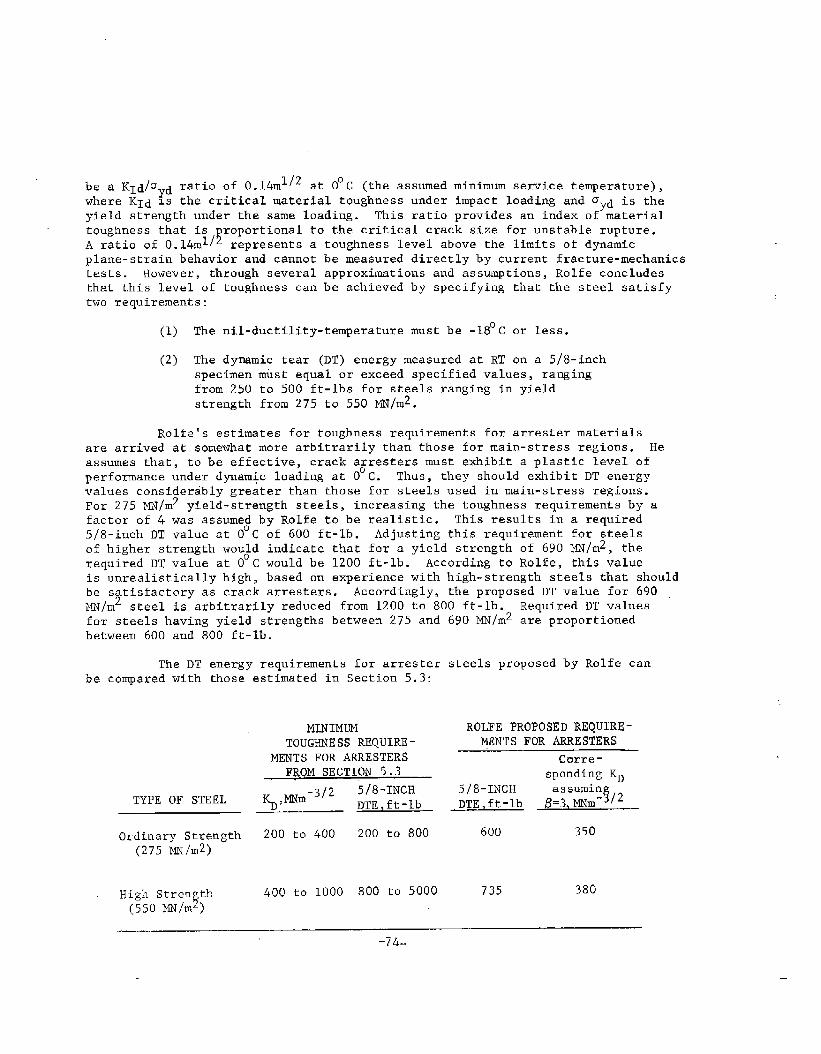
b15~ ~~d/oydratio of 0.14m1/2 at O“c (the assumed minimum service temperature),
where K1d IS the critical material toughness under impact loading and ~yd is the
yield strength under the same loading. ‘his ratio provides an index of materialtoughness that is ~roportional to the critical crack size for unstable rupture.A ratio of 0.14m1/ represents a toughness level above the limits of dynamicplane-s~rain behavio”r and cannot be measured directly by current fracture-mechanicstests. However, through several approximations and assumptions, Rolfe concludestha~ this level of toughness can be achieved by specifying that the steel satisfytwo requirements:
(1) The nil-ductility-temperature must be -18°C or less.
(2) The dymamic tear (DT) energy measured at RT on a 5/8-inchspecimen must equal or exceed specified values, rangingfrom 250 to 500 ft-lbs for steels ranging in yieldstrength from 275 to 550 MN/m2.
Rolfe’s estimates for toughness requirements for arrester materialsare arrived at somewhat more arbitrarily than those for main-stress regions. Heassumes that, to be effective, crack arresters must exhibit a plastic level ofperformance under dynamic loading at O°C. Thus , they should exhibit DT energy
values considerably greater than those for steels used in main-stress regions.For 275 MN/m2 yield-strength steels, increasing the toughness requirements by afactor of 4 was assumed by Rolfe to be realistic. This results in a required5/8-inch DT value at O°C of 600 ft-lb. Adjusting this requirement for steelsof higher strength would indicate that for a yield strength of 690 Yli/m2, therequired DT value at O°C would be 1200 ft-lb. According to Rolfe, this valueis unrealistically high, based on experience with high-strength steels that shouldbe satisfactory as crack arresters. Accordingly, the proposed DT value for 690PIN/rn2steel is arbitrarily reduced from 1200 to 800 ft-lb. Required DT valuesfor steels having yield s~rengths between 275 andbetween 600 and 800 ft-lb.
The DT energy requirements for arrester. ...7 ..,. . . . -F-
be comparea wltn LnOSe
TYPE OF STEEL
Ordinary Strength(275 MN/m2)
HigilStren th!(550MN/m )
MINIMUMTOUGHNESS REQUIRE-
MENTS FOR ARRESTERSFROM SECTION 5.3
200 to 400 200 to 800
400 to 1000 800 to 5000
690 MN/m2 are proportioned
steels proposed by Rolfe can
ROLFE PROPOSED REQUIRE-MENTS FOR ARRESTERS
Corre-sponding KD
5/8-INCHDTE,ft-~b &:3~/2
600 350
735 380
-7&

At ordinary strengths, Rolfe’s proposed requirements are seen to “bewithin the range of those estimated in Section 5.3. The range of values shownin the estimates from Section 5.3 for ordinary-strength steels is based on stresslevels ranging from 100 to 150 MIJ/m2and arrester spacings of from 3 to 6 meters.Rolfe’s proposed values, on the other hand, do not take these factors intoaccount. Thus,.the agreement for the two approaches is about as good as couldbe expected.
At high-strength levels, a major disagreement exists between Rolfe’sproposed requirements and those estimated in Section 5.3. Rolfe proposes onlymodest increases in DT’E (and the corresponding value of KD) as the yield strengthdoubles, while the estimate of Section 5.3 suggests that KD should be doubledand DTE quadrupled.
5.5 DATA FOR SHIP STEELS
Hawthorne and LOSS83
have characterized the DT properties of ordinarystrength shipbuilding steels, employing l-inch DT specimensy~. They found thata majority of the ordinary stren th hull grades cannot meet the Rolfe 5/8-inch
@DT.requirement of 600 ft-lb at O C (42oO ft-lb l-inch DT energy) for arresters.Their data show that only some of the AES Grade E and CS plates tested in thisstudy were able to meet these requirements. Of six plates of normalized GradesC and D steel, only one satisfied the Rolfe arrester requirement. None of thesteels tested was able to meet the most demanding of the DTE requirements estimatedin Section 5.3.
The problem in meeting the suggested DTE requirements for arrestersstems primarily from the fact that the transition temperatures of the ABS steelsare too high. Each of the grades tested by Hawthorne and Loss exhibited uppershelf 5/8-inch DTE values of 700 to 1400 ft”lbs (1-inch DTE of 5000 to 10,000ft-lbs). However, at O°C, most of the steels were within or below the transitionregion and the DTE values were correspondingly less. Heat-treated grades ofsteel generally exhibit lower transition temperatures and hence are more likelyto meet the suggested DTE requirements than are annealed or hot-rolled steels.
Rolfe, et al 5 have shown that heat treated ASTM 537A steel at a yield strengthof 380 MN/m2 has a 5/8-inch DTE value of 800 ft-lbs at O°C. Accordingly, forordinary-strength ship steels, it appears possible to achieve the estimatedrequired toughness levels for crack arresters if special attention is given toheat treatment to achieve low transition temperatures.
For higher strength ship steels, DTE data are sparse. Work in progressat Southwest Research Institute on SSC Project SR-224 will provide DTE data onsteels whose yield strength ranges from 345 to 690 MN/m2. Even though onlylimited information is available in this strength range, it appears certain thatthe high-strength grades will experience greater difficulty in reaching theestimated toughness requirements than do the ordinary-strength grades. As
7F correlations ~e~~een the 5/8.inch DT test and the l.inch DT test revealed
a ratio of about 1:7 for the respective DT energies.
_75-

strength increases, estimated arrester requirements go up and DTE shelf.levelsgo down.to employthickness
Thus , there is probably a strength level above which it becomes necessarymultiple thickness sandwiches of arrester plates in place of a single-in-plane crack arrester.
5.6 IMPLICATIONS FOR ARRESTER DESIGN
From the estfmates made in the foregoingone or two of the ordinary-strength grades of ship
sections, it appears that onlysteels currently available
will be useful as arresters to stop large propagating cracks and these perhapsonly marginally. This is clouded by uncertainty, however, both because ofproblems inherent in measuring the high-toughness values required of arrestersteels and because of incomplete analyses of ship structures. Accordingly,to design arresters effectively, it will be important that good analyses areavailable both for the test methods employed to evaluate the arrester steelsand for the various types of ship structure that might employ arresters.
The estimates made here suggest also that the toughness requirementsfor arresters increase dramatically with strength level, assuming a correspondingincrease in operating stresses. Since shelf-level toughness of steels decreaseswith increasing strength, it is likely that there is some cut-off strength levelabove which single-thickness in-plane arresters will be ineffective and multiplethickness sandwiches of arrester plates will be required.
–76-
-.

6.o CRITICAL COMI?ARISON OF CURRENT ANDPROPOSED CRACK ARRESTER CONCEPTS
The preceding sections of this report contain detailed descriptions Ofactual and proposed crack arrester systems for controlling fracture in ship hullsand other engineering structures. As a result of this intensive survey, it ispossible to categorize the arrester systems having potential for application toship hulls. A suggested categorization is given in Table 6.1.1.
It can readily be seen that the proposed categorization given inTable 6.1.1 is in accord with the energy-balance approach to crack propagationwhere crack arrest occurs when (and only when) the crack-driving force for thesystem, b, is no longer equal to the material’s fracture resistance. In termsof energy.based quantities, this idea can be expressed as
G < l?min , (6-1)
whereRmin denotes the minimum value of a crack-speed-dependent fracture-energy
requirement. Equivalently, the crack arrest idea can be expressed in terms of
the dynamic stress-intensity factoF K and the minimum dynamic fracture-toughness
‘D,min as
K < KD,min . (6-2)
Thus, a Class I arrester system is one in which the primary aim is to increase
~ (or KD ~in)> a Class 11 arrester is one that primarily decreases .4(or K),while a ~lass III arrester is one in which both an increase in R and a decreasein .&occurs simultaneously. From an analysis point of view, Class I is the simplestto treat; Class III is the most difficult.
One constraint that has been imposed on the critical comparison of crackarrester systems in this report is that the scope of this program precludes anyexperimental work or any large-system computations. Yet, on the basis of theresults exhibited in Section 3, dynamic analyses appear to be required to properlyevaluate the candidate systems. This points to the desirability of making theevaluations within the framework of a relatively simple physical situation wherethe various effects can be properly taken into account. On this basis, the DCBtest specimen has been selected for the purpose of this report.
Figure 6.1.1 shows a set of hypothetical experiments in which variouskinds of crack arrester systems are to be tested. The analysis of each event canbe made by a relatively straightforward modification of the DCB dynamic analysispresented in Section 3.6.2. Omitting the mathematical details, the extensionskequired to treat each of the cases shown in Figure 6.1.1 are as
(A) High-toughness insert--consider that the materialthe arrest section obeys a different KD = KD(~)relation than that of the base material.
-77-
follows:
in

TABLE 6.1.1. CRACK ARRESTER SYSTEMS FOR SHIP HULLS
Class General Description Key Properties Examples
I Arrester systems that presen”tthe Fracture toughnesses (1) High-toughnesspropagating crack with a higher of base plate and integral insertfracture energy requirement without arrester material. (2) Continuously bondedat the same time introducing any stiffenersappreciable change in structure {3) Increased platesriffness. thickness
11 Arrester systems that decrease the Elastic modulus, area (1) Intermittently at-crack driving force by imposition of and strength of base tached stiffeners
I< some mechanical agency in the antici- pate and arrester (2) Pretensioned cablesy pated crack path thus changixg the material (3) Residual compressive
stiffness of the structure. stress
III Arrester systems that direct or Fracture toughness of (1) Riveted platesdivert the crack from a potentially of base plate and arrester (2) Ditch-type arresterdetrimental path andlor change the material (if any); modulus, (3) Weldsfracture mode of the propagating area, and strength of thecrack by simultaneously changing structural components.both the crack driving force and thefracture dissipation energy.

(B) Integral stiffener--introduce a change in stiffnessdue to a locally increased thickness of an arrsstsection and increase the fracture area accordingly.
(C) Intermittently attached stiffener--include the restrain-ing effect of stiffener by increasing the springstitfnesses ke and kr in the arrest section.
(D) Constant-tension cables-- introduce compressive forcesinto the equations of motion at positions correspondingto the cable locations.
Note that in Cases (C) and (D), one important parameter of the arrester system--the stiffener spacing or the cable length--can be introduced, but not varied.That is, these lengths must be related to the specimen height dimension h.However, this should not be important here because only qualitative comparisonsof the various systems are sought.
Computational results typifying the analysis of crack arrester systemsusing the DCB specimen are given and discussed in the following. These computationswere made for three different types of arrester systems positioned such that arapidly moving crack must pass through it soon after being initiated. The basicdimensions of the DCB specimen are as given in Section 3.6.3. The arrester sectiondimensions are given by d = 75 mm and f = 25 mm for the inserted strip and inter-mittently bonded devices, cf. Figure 3.6.2. For the constant tension system,the force is taken at the position x = 75 mm.
The integral stiffener, Type (B), will be similar to Type (A) or Type (C),depending on whether the stiffener does or does not fracture. Consequently,there are three distinct arrester types that need to be considered. Note that,for convenience, a speed-independent dynamic fracture toughness was used in allof the following calculations, i.e., KD = KIC.
Calculations on the high-toughness inserted strip crack arrester, Type(A) in Figure 6.1.1, are shown in Figure 6.1.2. The ratio of the fracturetoughness of the arrester strip relative to the base material was systematicallyvaried to determine the effect on the crack arrest point. Figure 6.1.2(a) showsthe crack length predictions as”a function of time for the case where Kq = 2.0 KIC.Figure 6.1.2(b) shows the predictions of the arrest point as a function of therelative fracture-toughness levels of the arrester and the base material. It can
be seen by comparison of Figure 6.1.2(b) with Figure 3.6.7 that the static theorybadly overestimates the effectiveness of the arrester device. Other differenceswith the static theory can also be seen. For example, in the static approximation,if the crack does not stop -in the arresrer section, the arrester has no effecton it. The dynamic calculations shown in Figure 6.1.2 reveal that this is notthe case, however. The energy dissipated in the arrester always diminishes thecrack-driving force to some extent, causing arrest before it would normally haveoccurred even when it takes place beyond the arrester section.
Calculations on the intermittently attached stiffener crack arresterdevice, Type (C) in Figure 6.1.1, are shown in Figure 6.1.3. Figure 6.1.3(a)shows the crack length versus time calculations for the case where Kq = 2.0 KIC
-79-
....—-

*DRD -m)
40ml“
‘1. 100 00
LDO 1Oe.
-80-
-. .-

while Figure 6.1.3(b) shows the crack arrest point as a function of the relativewidth of the stiffener and the base plate. Note that the elastic modulus ofthe stiffener was taken to be the same as that of the base plate (i.e., E =20,6850 N/mmz for steel) and the width of the stiffener was fixed at 25 mm.
Hence, the only arrester dimension varied was the stiffener thickness.
It can be seen from Figure 6.1.3(b) that, just as for the high-toughness insert, the arrester has an effect on the eventual arrest pointeven when the crack passes through it. The mechanism differs, however, as theamount of fracture energy is not changed by this kind of arrester. Instead,the mechanical restraint on the crack~tip region, particularly as the crackpasses abreast of it, reduces the crack-driving force. In terms of the classif-ication given in Table 6-1, the high-toughness strip is a member of Class I.The intermittently a~tached stiffener is a member of Class II.
Calculations on the constant-force (e.g., pretensioned cable) crackarrester system, Type (D) in Figure 6.1.1, are given in Figure 6.1.4. Crack-propagation-time calculations for Kq = 2.0 KIc are given in Figure 6.1.4(a).The relative crack-arrest points as a function of the compressive force exertedby the device on the specimen are shown in Figure 6.1.4(b).
It can be seen that the same general effects are exhibited for theconstant-force device as were evident in the results shown for the intermittentlyattached stiffener. This should not be entirely unexpected as this case is alsoa member of Class 11. In fact, it can be viewed as the special limiting caseof an elastic-perfectly plastic stiffener that has completely yielded. Anotherphysical interpretation of this kind of arrester representation is in terms ofa compressive residual stress field in the path of the moving crack.
The results ,shown for the various crack arresters,in Figures 6.1.2,6.1.3, and 6.1.4 can be used to emphasize a very essential point. This is thatthere can be no absolute measure of the effectiveness of a crack arrester system.The reason Ts that whether or not a crack is arrested by a given device dependson a great many key factors in actual applications. The most important of thesevar%ables are
● The geometry of the structure in which the arresteris installed and its specific location in the structure
● The loads acting on the structure, both at the time ofcrack growth initiation and while the crack is running
g The speed, direction, and length of the crack as itreaches the vicinity of the arrester.
The environment, particularly the temperature , as it affects the relativestrength and toughness levels of the arrester and the base material will alsoplay a key role.
It is a design problem to determine the most severe conditions to beexpected in any application and proceed accordingly. But , any such conditionswill be specific to a given application and will not be general enough to serve
-sl-

KU/K=.20CinchamztMynamicl,
f[3.3- 15.161
M“
#
00 ! , I
20 w 60 Bo la ,20
t. Time Fmm lnitiotkm of Gra.th [,UWC1
FIGURE 6.1.3(a). COFfFARISON OF CRACKARREST POINTS PREDICTED BY A FULLYDYNAMIC ANALYSIS WITH THAT OF AQUASI-DYNAMIC ANALYSIS FORA STAND-
ARD DC13SPECIMEN WITH ~ = KIC
,,0.= E!w!o 00 0,2A 0.6
%iidPoitifsdemfe12s- crock drrest
O*
zg 100 -
;
ee
~ 75 -
G.
m“position of nrrcatm
❑ Sa --------- .ti.&~-------------
a
00 20 40 60 80 IoO 1=t. Time Since lmtmlio. of Crock Growth (p-~
FIGURE 6.1.4(a). CRACK PROPAGATIONCOMPUTATIONS FOR A DCB SPECIMENWITH A CONSTANT-TENSION CMCKARRESTER DEVICE FOR Kq/K1c = 2.0
+44==
Wb
FIGUW, 6.1.3(b). CALCULATED CRACKARREST POINT IN A DCB SPECIMENWITH AN INTERMITTENTLY-ATTACHEDSTIFFENER CRACK ARRESTER AS AFUNCTION OF THE STIFFENERTHICKNESS
..or
P
2.0
J3.
m - ---- POs,t,m of Arrester_--— _____ --_.—— ______
1Wooo aoo( amz CIC03 0W4
&EM
FIGURE 6.1.4(b). CALCULATED CRACKARREST POINT IN A DCB SPECIMENWITH A CONSTANT-TENSION C&iCKAKRESTER DEVICE AS A FUNCTION OFTHE FORCE APPLIED TO THE SPECIMEN
-82-
—.-,—-..——— . .. _ -.
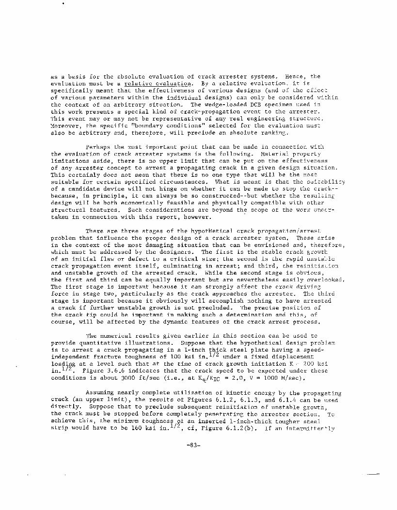
●
as a basis for the absolute evaluation of crack arrester systems. Hence, theevaluation must be a relative evaluation. By a relative evaluation, it isspecifically meant that the effectiveness of various designs (and of rhe effectof various parameters within the individual designs) can only be considered withfnthe context of an arbitrary situation. The wedge-loaded DCB specimen used inthis work presents a special kind of crack-propagation event to the arrester.This event may or may not be representative of any real engineering structl~re.Moreover, the specific “boundary conditions” selected for the evaluation mus~
also be arbitrary and, therefore, will preclude an absolute ranking.
Perhaps the most important point that can be made in connectio~.withche evaluation of crack arrester systems is the following. Material propertylimitations aside, there is no upper limit that can be put on the effectivenessof any arrester concept to arrest a propagating crack in a given design siruation.This certainly does not mean that there is no one type that will be the mostsuitable for certain specified circumstances. What is meant is that the sufcability
of a candidate device will not hinge on whether it can be made to stop the crack---because, in principle, it can always be so constructed--but whether the res~ltingdesign will be both economically feasible and physically compatible with other
stmctural features. Such considerations are “beyond the scope of the work um5cr-taken in connection with this report, however.
There are three stages of the hypothetical crack propagation/arrestproblem that influence the proper design of a crack arrester system. These artsein the context of the most damaging situation that can be envisioned and, therefore,which must be addressed by the designers. The first is the stable crack growtkof an initial flaw or defect to a critical size; the second is the rapid unstel>kcrack propagation event itself, culminating in arrest; and third, the reiniti~t.io~and unstable growth of the arrested crack. While the second stage is obvious,the first and third can be equally important but are nevertheless easily overbooked.
The first stage is important because it can strongly affect the crack drivingforce in stage two, particularly as the crack approaches the arrester. The thirdstage is important because it obviously will accomplish nothing to have arres~eda crack if further unstable growth is not precluded. The precise posi~ion ofthe crack tip could be important in making such a determination and this, ofcourse, will be affected by the dynamic features of the crack arrest process.
The numerical results given earlier in this section can be usec?toprovide quantitative illustrations. Suppose that the hypothetical desig.~problemis to arrest a crack propagating in a l-inch thick steel plate having a speed-independent fracture toughness of 100 ksi in.1/2 under a fixed displacenen~
loading at a level such that at the time of crack growth initiation K= 200 ksii~_l/2. Figure 3.6.6 indicates that the crack speed to be expected under theseconditions is about 3000 ftlsec (i.e., at Kq/KIc = 2.0, V = 1000 M/see).
Assuming nearly complete utilization of kinetic energy by the propagatingcrack (an upper limit), the results of Figures 6.1.2, 6.1.3, and 6.1.4 can be useadirectly. Suppose that to preclude subsequent reinitiation of unstable growth,the crack must be stopped before completely penetrating the arrester section. TO
achieve this, the minimum toughness of an inserted l-inch-thick tougher steelstrip would have to be 160 ksi in.1~2, cf, Figure 6.1.2(b). If an intermi~tently
-83-

TABLE 6.1.2. EXAMPLE CALCULATIONS FOR THE DESIGNOF THREE DIFFERENT CRACK ARRESTERSYSTEM TYPES
Minimum Value of Design Variable(b)
Crack Arrester Design
System(a) Variable Kq = 200 ksi in.1/2
Kq= 300 ksi in.1/2
High toughness Fracture 160 ksi in.112 270 ksi in.112
integral inserted toughnessl-inch wide strip of arrester
Intermittently Stiffener 0.35 inch 1.20 inch
attached l-inch thfckness
wide sriffener
Pretensioned cable Stress in 60 ksi 160 ksi
l-inch2 cross cable
sectton
(a)
(b)
Arrester system dimensions are relative to a l-inch thick steel base plate havinga speed-independent dynamic fracture toughness of 100 ksi in.
1/2
The parameter Kq represents the applied load-flaw size combination that existedat the time of unstable crack growth initiation. Fixed displacement boundary
conditions are assumed during craclcpropagation.
attached l-inch-wide stiffener device is to be used, it would have to be 0.35 inchin thickness; cf, Figure 6,1.3(b). Finally, if a pretensioned cable with a cross-sectional area of 1 in.2 is to be used, it must be stressed to at least 60,000 psi;cf, Figure 6.1.4(b).
To further emphasize the key variables that influence the requirementsfor an arrester device, calculations have also been made for the higher initialload level of 300 ksi in.112. The arrester parameters obtained for the threecases given in Figures 6.1.2, 6.1.3, and 6.1.4 are summarized along with theabove results in Table 6.1.2. The significant effect of the load level (or,equivalently, the fracture speed) is obvious from these results. Note finallythat these results are based on a geometric configuration that is a much moreefficient utilizer of kinetic energy than are actual ship hull structures. But,while over-estimating the minimum arrester parameters, these results have thevirtue of automatically incorporating a factor of safety which more than likely
would always be inserted in any event.
-84-
— ..,.

7.0 RECOMMENDATIONS FOR FUTURE RESEARCH
There are two major points that have been identified in the work reportedhere that bear on the proper design and utilization of crack arrester systems forship hulls. The first is that there is no general type of system that can beidentified as being completely superior to all others in all circumstances. Thereason is that, in principle, there is no upper limit to the crack arrestingcapability of most arrester systems.~’fBy choosing materials and sizes properly,most systems can be made to have sufficient “stopping power” in any conceivablesituation. Consequently, the choice of an arrester system probably rests mainlyon economic considerations (e.g., cost of materials, installation and fabricationcosts), material availability, and other design considerations (e.g., potentialcrack initiation .sTtesintroduced, the effect of the arrester on the performanceof the vessel), not on any limits on the effectiveness of the arrester system.
The second major point is connected with the design of the arrestersto be used in a given application. Once the particular arrester system has beenselected, an exact quantitative evaluation must be performed. In performing thisevaluation, numerical calculations based on a fully dynamic theory of elasticitysolution procedure with boundary conditions properly taken into consideration arerequired. In short, statically based calculations can be highly misleading withregard to the crack arrest capability of a given arrester system and structuralconfiguration. The extent to which this is true cannot be determined at this timeand, in fact, is a highly appropriate area for further research, as described below.
In performing an analysis of a crack arrester device for a specificship hull, it is obviously necessary to have a detailed, albeit preliminary,knowledge of the ship hull configuration (e.g., mechanical properties, platethicknesses, stringer stiffnesses and spacings). A basis for estimating theseverity of the loads that will be acting on the ship hull in the vicinity ofthe crack arrest device must also be known. It is then necessary to anticipatewhere an unstable crack might initiate and the direction in which it might beexpected to propagate. These are pieces of information thht a ship designerwould normally have at hand. 13ut,there are three additional general aspectsof the problem in which a specific capability is also needed to properly designthe arrester. These are
e A way of estimating the growth of a flaw by fatigueduring anticipated service conditions for the ship
@ A way of evaluating the mechanical and fractureproperties of the ship hull and arrester devicewhen presented with a fast-running crack
o A practical computational method for performing dynamiccalculations for rapid crack propagation and crack arrestin a given structural configuration.
~~ All systems clearly have a practical limitation because of the mechanicalproperties of the materials that are available. Material considerationsaside, with the further exceptional cases of devices such as the ditch-typearrester being excluded, an arrester system can always be adequately designedfor a given situation.
-85-

In contras~, these capabillries are not ordinarily available to ship designers.In fact, it can be safd that in none of these three areas has enough fundamentalwork been done to provide ship designers with the techniques required to do hisjob properly. These areas therefore represent potential topics in which researchcan be recommended to provide a design basts for the proper design of ship hullcrack arrester systems.
In accordancegiven in this report, a
ITIno particular order,
1.
2.
3.
4.
A pro~ram
with the conclusions that have been drawn from the worknumber of recommended research topics can be proposed.these are as follows.
of experiment and analysis to obtain atechnique for estimating the rate of fatigue crackgrowth in ship hull materials for the load spectrumthat a vessel would be expected to experience undersevere, but probable, service conditions. The resultsof this work will likely show that fatigue crack-growthrates are primarily dependent on the type of ship andthe geographical locations in which it is expected toserve. This work could take advantage of the largebody of work already performed for aircraft structures.
A program of experiment and analysis aimed atdetermining the dynamic fracture properties ofpresent-day and contemplated ship hull and arrestermaterials. This program will likely be based upondeveloping (or modifying) a standardized laboratorytest specimen. Since there is no way to directlymeasure dynamic fracture-toughness values, thesemust be inferred from test quantities that are directlymeasurable. Hence, the need for an analysis capabilityin such a program. It should in any event be reempha-sized that the dynamic fracture-toughness values arenot generally the same as their static counterparts and,in some instances, can be qufte different. Work inthis area should draw upon the extensive progress thathas been made on behalf of the NRC and others.
A program to develop a two-dimensional dynamic analysiscapability for treating fast-movtng cracks in realengineering structures. Because of the generalitythat is needed to treat arresters, the tool that mustbe evolved will be based on a numerical analysistechnique (e.g., finite different method) and willtake the form of a computer program. Such programsare already available. What is needed is that theybe extended to explicitly treat arresters.
A program to develop an elastic-plastic dynamic fracture-mechanics capability for the initiation of unstable crack
Propagation from arrested cracks. With the high-toughness
levels used in ship steels, particularly in arrester
-86-
—

sections, ordinary linear elastic fracture-mechanicstreatments are quite inappropriate. In particular,
stable crack growth cannot be treated within the linearelastic regime, and this may be a key factor in deter-mining the point at which a fast fracture arrested ator near an arrester can become critical once again.Some work is under way in this area “buthas only scratchedthe surface of this formidable problem.
5. A research program to evaluate and make available theresponse of a ship under service conditions in a systematicmanner. It is recommended that research programs bepursued using model and full-scale experiments to determineship responses in random seas. These data should beutilized to advance the currently available linear striptheory programs on various ship classes. Then the researchresults in the areas of fracture mechanics and probabilisticdesign approaches can be integrated into useful tools forthe ship designer. Currently, the ship designer is awareof meaningful research results in a number of areas, but hedoes not have the time or knowledge to apply these new datato his designs. The ship response effort is also requiredto determine ship springing and related elastic strains topredict the adequacy of crack axresters to stop dynamiccracking. A significant body of work already exists asa result of Ship Structure Committee work in this field,of course.
It might be noted that a research program confined to one of these topics andexcluding other aspects of the problem could be quite ineffective. A researchprogram that has proper design of crack arrester systems tor ship hulls as itsobjective must be cognizant of all of the various aspects of the crack propagation-arrest problem to be truly beneficial.
Consider one example problem to help make these ideas more concrete.Figure 7.1.1 shows a section of a ship hull that is periodically reinforcedby riveted stiffeners. Suppose that a crack initiates at the rivet hole (as theyoften do) and grows by fatigue under the normal loadings carried by the ship whilein service. Further suppose that the ship is exposed to storm conditions severeenough to cause the crack to propagate unstably across the hull plate towards themost vulnerable part of the stiffener reinforced region--the point midway betweenthe rivets in the adjacent stiffener. The first question is will the crack bestopped at the stiffener or will it pass under it and, likely, tear apart theentire hull in the process? The second question is, assuming that the crack hasbeen arrested at the first stiffener, can unstable crack growth be subsequentlyreinitiated?
The ship designer can readily anticipate the scenario illustrated inFigure 7.1.1 and outlined above. The obvious problem that he is faced with inthis circumstance is to insure that the crack is arrested at the stiffener. Whathe must do to achieve this is have the stiffener constrain the dynamic crack drivingforce as the propagating crack tip approaches it so that the dynamic stress-intensity
-87-
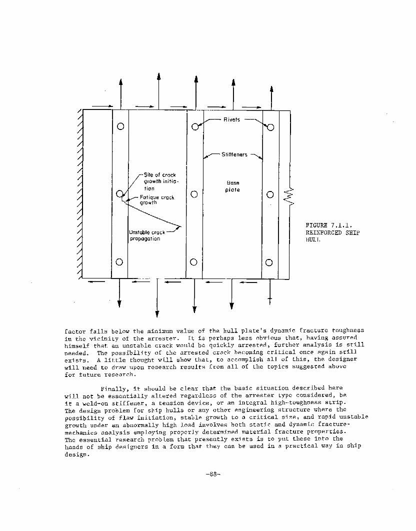
/ “
/
//
/
/
/
/
/
/
/
/
/
A
L____.uo
LSite of crock
growth initia-
tion
Fatigue crack“..
,. growth
Unstable crack
propagation
— Rivets _
-Stiffeners ~
Base
plate
factor falls belowin the vicinity of
fFIGURE 7.1.1.REINFORCED SHIPHULL
the minimum value of the hull plate’s dynamic fracturethe arrester. It is perhaps less obvious that, having
himself that an unstable crack would be quickly arrested, further analysis is still
toughnessassured
needed. The possibility of the arrested crack becoming critical once again srillexists. A little rhought will show that, to accomplish all of this, the designerwill need to draw upon research results from all of the topics suggested abovefor future research.
Finally, it should be clear that ~he basic situation described herewill not be essentially altered regardless of the arrester type considered, beit a weld-on stiffener, a tension device, or an integral high-toughness strip.The design problem for ship hulls or any other engineering structure where thepossibility of flaw initiation, stable growth to a critical size, and rap%d unstablegrowth under an abnormally high load involves bo~h static and dynamic fracture-mechanics analysis employing properly determined material fracture properties.
The essential research problem that presently exists is to put these into thehands of ship designers in a form that they can be used in a practical way in shipdesign.
8.0 REFERENCES
1. Hinners, R.A., contributed discussion to Reference 3, Sot. NavalArch. Marine Eng. Trans. 75, 380 (1967).
2. Boyd, G.M., “Fracture Design Practices for Ship Structures”, Fracture,H. Liebowitz (editor), ~, 383, Academic Press, New York (1969~—
3. Heller, S.R., Jr., Lytle, A.R., Nielsen, R., Jr., and Vasta, Jr.,“Twenty Years of Research Under the Ship Structure Committee”, SOC.Naval Arch. Marine Eng. Trans., 75, p 332 (1967).
5. Chazal, E.A., Jr., Goldberg, J.E., Nachtsheim, J.J., Rumke, R.W.,and Stavovy, A.B., “Third Decade of Research Under the Ship StructureCommittee”, presented at Ship Structure Symposium, Washington, D.C.,October 6-8, 1975.
5. Rolfe, S.T., Rhea, D.M., Kuzmanovic, B.O., “Fracture-Control Guidelinesfor Welded Steel Ship Hulls”, Ship Structure Committee Report SSC-244 (1974).
6. Kihara, Kanazawa, Ikeda, Okabe, Nakijima, Lajima, Mitsubishi HeavyIndustries, Ltd., “Study on Welded–Type Crack Arrester (First Report)”,June,1972.
7. Yajima, Nakajima, Okabe, Nagamoto, “Study on Welded-Type Crack Arrester,
(First Report)”, Tech. Review, Vol. 8, No. 2, June ,1971.
8. Kanazawa, Machida, Yajima, Aoki, “Study on Brittle Crack Arrester-Con-
siderations on the Arrest of a Very Long Crack”, J.S.N.A., Japan, Vol. 131,June J972.
9. Kanazawa, 14achida,Matola, “Some Basic Considerations on Brittle Crack
Arrester for Welded Steel Structures (First Report)”, J. SOC. Naval Arch,Japan.
10. Kanazawa, et al., Ibid (2nd Report) - Patch Type, VO1. 116, 1964.
11. Yoshiki, et al., Ibid (3rd Report) - Experimental Checks, Vol. 118, 1964.
12. W.M. Hannan, “Classification Society Experiences in Today’s Ships” presented
at Ship Structures Symposium, Washington, D.C. , October 6-8, 1975.
13. G. Buchanan, Jensen, C.J.G., Dolson, Dr.R., “Lloyd’s Regfster of Shipping’sApproach to the Control of the Incidence of Brittle Fracture in ShipStructures”, Lloyd’s Register Report No. 56, 1969.
14. Kanazawa, Machida, Yajima, Aoki, “Study on”Brittle Crack Arrester - Con-
siderations on the Arrest of a Very Long Crack”, J.S.N.A. , Japan, Vol. 130,December, 1971.
-89-

15.
16.
17.
13.
19.
20.
21.
22.
23.
24.
25.
26.
27.
28.
REFERENCES (Continued)
Kanazawa, tiachida, Aoki, “Fracture Mechanics AnalysesStiffner-Type Crack Arrester”, Japan Shipbuilding andVol. 3, No. 6, November, 1968.
and Design ofMarine Engineering,
Yoshiki, Kanazawa, Machida, “Fracture Mechanics Analysis of Stiffner-TypeCrack Arrester”, J.S.N.A., Japan, Vol. 118, December,1965, Vol. 122,December,1967, Vol. 124, December, 1968.
Gammall, M.M., “A New Method for Estimating the Fatigue LifeStructures”, University of Newcastle Upon Tyne, July, 1975.
Nibbering, J.J.W., “Fracture Mechanics and Fracture ControlNetherlands Ship Research Center TNO, Delft, Report No. 178May, 1973.
of Ship
for Ships”,S(1771SC)
“Brittle Fracture Tests for Weld Metal”, Concept Final Report of IIWWorking Group 291.2,Reporr No. 185, Ship Structures Laboratory, DelftUniversity of Technology, Dec. X-754-74, May, 1974.
Kavlie, Dag., “Notes on Steel Grades vs. Temperature and Thickness forVarious Ship Hull Members”, University of Trondheim, Norges TekniskeHogskole, June, 1975.
Lerde, N.G,, “Review of Crack Arresting Experience and Development from
Kockums”, September 17, 1975.
Stenberg, Fer, Svetsaren,that All-Welded Ships are1950.
Liston, Haskins, “TensileReport No. 62, 1969.
“Has the Experience of Recent Years ConfirmedShips of the Future?”, No. 2-3, Vol. 15, p 32,
Testing of Steel”, Lloyd’s Register of Shipping
Broek, D., Elementary Engineering Fracture Mechanics, Noordhoff, 1974.
Mott, N.F., Engineering 165, 16 (1948).
Kanninen, M.F., Int. J. Frac., 10, 415 (1974).
Freund, L.B., J. Mech. Phys. Solids, 20, 129 (1972).
Hahn, G.T., Gehlen, P.C., Hoagland, R.G., Kanninen, M.F., Popelar, C.,Rosenfield, A.R., and de Campos, V.S., “Critical Experiments, Measurements
and Analyses to Establish a Crack Arrest Methodology For Nuclear Pressure
Vessel Steels”, Report to Div. Reacror Safety Research, U.S. NuclearRegulatory Commission, 13MI-1.937,August, 1975.
-q!j--

29.
30.
31.
32.
33.
34.
35.
36.
37.
38.
39.
40.
41.
42.
43.
44.
45.
Eftis, J. and Krafft,
REFERENCES (Continued)
J.M., J. Basic Eng., ASME 257, March, 1965.
Barton, F.W. and Hall, W.J., Weld. J. Res. Supp., 39, 379s, 1960.
Hahn, G.T., Hoagland, R.G., Rosenfield, A.R., and Sejnoha, R., Met.Trans. , 5, 475, 1974.
Burns,S.J. and Bilek, Z.J., Me’cl. Trans., 4, 975, 1973.
Fearnehough, G.D., “Fracture Propagation Control in Gas Pipelines”,Crack Propagation in Pipelines, Paper No. 1, The Institution of Gas
Engineers, London, 1974.
Freed, CAN., Sullivan, A.M., and Stoop, J., “Effect of Sheet Thicknesson the Fracture-Resistance Parameter K~ for Steels”, NRL Report 7601,1973.
Freed, C.N., Sullivan, and Stoop, J., “Effect of Sheet Thickness onthe Fracture-Resistance Parameter Kc for Steels”, NRL Report 7464, 1972.
Sullivan, A.M., Stoop, J., and Freed, C.N., “Influence of Sheet ThicknessUpon the Fracture Resistance of Structural Aluminum Alloys”, ASTM-STP,Vol. 536, pp 323-333, 1973.
Krafft, J.M., and Irwin, G.R., ASTM STP 381, 114, 1964.
Hahn, G.T., Hoagland, R.G., Kanninen, M.F., Rosenfield, A.R., “crackArrest in Steels, Eng. Fract. Mech., Vol. 2, p 583, 1975.
Irwin, G., Handbook of Physics, ~, 551, 1968.
Shabbits, W.O., Dynamic Fracture Toughness Properties of Heavy SectionA533B Class 1 Steel Plate. WCAP-7623, (HSSTP-TR 13) Westinghouse,December, 1973.
Crosley, P.B., and Ripling, E.J., Trans., ASME 91, Series D, 525, 1969.
Irwin, G.R., and Wells, A.A., Met; Rev., 10, 223, 1965.
Crosley, P.B., and Ripling, E.J., Nucl. Engng Design, 17, 32, 1971.
Crosley, P.B., and Ripling, E.J., Materials Research Laboratory Report,Glenwood, Illinois, 1970.
Crosley, I?.B., and Ripling, E.J., Proc. 2nd Int. Conf. Pressure VesselTech. , October, 1973, San Antonio, Texas.
-91-

., —
REFERENCES (Continued)
46. Yoshilci, M., Kanazawa, T., and Machida, S., “Fracture Mechanics Approachto Brittle Fracture Propagation-Arrest in Structural Steel,” E’roc.First Int. Conf. Fracture, 1965, Vol. 3, p 1711.
47. Kanazawa, T., “Recent Studies on Brittle Crack Propagation and Arrestfor a Material having a Crack Speed Dependent Fracture Toughness”,Presented at the Conf. on the Prospects of Fracture Mechanics, Delft,Netherlands June 24-28, 1974.
48. Kanninen, M.F., “An Analysis of Dynamic Crack Propagation and Arrestfor a Material having a Crack Speed Dependent Fracture Toughness”,Presented at the Conf. on the Prospects of Fracture Mechanics, Delft,Netherlands June 24-28, 1974.
49. Romualdi, G.P., Frasier, G.T., and Grwin, G.R., “Crack Extension ForceNear a Riveted Stringer”, NRL 4956, 1952.
50. Poe, C.C., “The Effect of Riveted and Uniformly Spaced Strfngers on theStress-Intensity Factor of a Cracked Sheet”, AFFDL-TR-70-144, 1970, pp207-216.
51. Poe, C.C., “Fatigue Crack Propagation in Stiffened Panels”, ASTM STP 486,American Society for Testing and Materials, pp 79-97, 1971.
52. Vlieger, H., “Residual Strength of Cracked Stiffened Panels”, NLR T.R-711304,1971.
53. Vlieger, H., “The Residual Strength Characteristics of Stiffened PanelsContaining Fatigue Cracks”, Eng. Fracture Mechanics, 5 pp 447-478, 1973.
54. Swift, T., and Wang, D.Y., “Damage Tolerant Design Analysis Methods andTest Verification of Fuselage Structure”, AFFDL-TR-70-144, 1970, pp
653-683.
55. Swift, T., “Development of the Fail-Safe Design Features of the DC-10”ASTM STP 486, American Society for Testing and Materials, pp 164-214, 1971.
56. Swift, T.,“The Effect of Fastener Flexibility and Stiffener Geometry,on the Stress Intensity Factor in S’cfffened Sheet’!,Prospects of FractureMechanics, Sih et al editors, Noordhoff, 197b, pp 41~436.
57. Hahn, G.T,, Hoagland, R.G., Kannfnen, M.F., and Rosenfield, A.R.,
Sejnoha, R., “Fast Fracture Resistance and Crack Arrest in Structural
Steels”, Ship Structure Committee Report SSC-242.
-92-

REFERENCES (Continued)
58. Hahn, G.T..,Hoagland, R.G., Kannlnen, M.F., and Rosenfie~d, A.R,,
Dynamic Crack Propagation, edited by G.C. Sih (Noordhof), pp 649,1973.
59. Hahn, G.T., Hoagland, R.G., Kanninen, M.F., and Rosenfield, A.R.,A, Pressure Vessel Technology, Part 11, ASME, New York, p 981-994,1974.
60. Hahn, G.T., Hoagland, R.G., Kanninen, M.J?., and Rosenfield, A.R., B,Pressure Vessel Technology, Part 111, ASME, New York, p 121, 1974.
61. Hahn, G.T., Hoagland, R.C., Kanninen, M.F., and Rosenfield, A.R,,“Pilot Study of Fracture Arrest Capabilities of A533B Steel”, (to bepresented at Ninth National Symposium Fract. Mech., Pittsburgh, 1975),1975.
62. Hahn, G.T., Hoagland, R.G., and Rosenfield, A.R., “Dynamic CrackPropagation and Arrest in Structural Steels”, Final Report on ProjectSR-201 to Ship Structure Committee, 1975.
63. Hoagland, R.G., Trans. ASME, Vol. 89, (Ser. D), p 525, 1967.
64. Hoagland, R.G., Kanninen, M.F., Rosenfield, A.R., and Hahn, G,T.,“Rectangular-DCB Specimens for Fast Fracture and Crack Arrest
Measurements, Topical Report to NRC, Div. Reactor Safety Research, 1974.
65. Hoagland, R.G., Rosenfield, A.R., and Hahn, G.T., Met. Trans., Vol. 3P 123, 1972.
66. Kanninen, M.F., Int. J. Fract. Mech., Vol. 9, p 83, 1973.
67. Kanninen, M.F., B. Proc. Cont. on Prospects of Fracture Mech., G.C.Sib, et al., editors, Nordhoff, Leyden, The Netherlands, ~ 251, 1974.
68. Freund, L.B., B, J. Mech. Phys. Solids, Vol. 20, p 141, 1972.
69. Freund, L.B., J. Mech. Phys. Solids, Vol. 21, p 47, 1973.
70. Francis, P.H., Landford, J., and Lyle, F.F., “A study Of subcritical
Crack Growth in Ship Steels”, Final Technical Report on SR-20, 1974.
71. Pelloux, R.M.N., “Review of Theories and Laws of Fatigue Crack Propa-gation”, AFFDL-TR-70-144, 1970, pp 409-416.
-93-
.—.
72. Erdogan, F., “Crack Propagation Theories”, NASA CR-901, 1967.

REFERENCES (Continued)
73. Toor, P.M., “A Review of Some Damage Tolerance Design Approaches forAircraft Structures”, Eng. Fracture Mechanics, ~, pp 837-880, 1973.
74. Schijve, J., and Broek, D., “Crack Propagation Tests Based on a GustSpectrum with Variable Amplitude Loading”, Aircraft Engineering, ~,pp 314-316, 1963.
75. Schijve, J., “Cumulative Fatigue Problems in Aircraft Structures and
Materials”, Aeronautical Journal, ~, pp 517-532, 1970.
76. Corbly, D.M., and Packman, P.F., “On the Influence of Single andMultiple Peak Overloads on Fatigue Crack Propagation in 7075-T6511Aluminum”, Eng. Fracture Mechanics, ~, pp 449-497, ~gi’s.
77. Willenborg, J., Engle, R.M., and Wood, H.L4., “A Crack Growth RetardationModel Using an Effective Stress Concept”, AFFDL-TM-71-lFBR, 1971.
78. Landis, J.D., and Begley, J.A., ‘“he Effect of Specimen Geometry on JIC”,
ASTM STP J14, p 24, 1972.
79. Robinson, J.N., and Tetelman, A.S., “The Critical Crack-Tip Opening
Displacement and Microscopic and Macroscopic Fracture Criteria forMetals”, UCLA-ENG-7360, Tech. Report No. 11 to U.S. Army Researchoffice, Dur~am On Contr. DAHc04-69-C-OO08, August, 1973.
80. Shoemaker, A.K., and Rolfe, S.T., The Static and Dynamic Low-
Temperature Crack-Toughness Performance of Seven Structural Steels”,Eng. Fract. Mech., vol. 2, p 319, 1971.
81. Barsom, J.M., and Rolfe, S.T., “KIc Evaluation-Temperature Behavior
of A517-F Steel”, Eng. Fract. Mech.~ VO~. 2, P 341J 197~-
82. Unpublished NRL data.
83. Hawthorne, J.R., ancl LOSS, F.J., “Fracture Toughness Characterization
of Shipbuilding Steels”, SSC-248, 1974.
84 Nilsson, F., “A Note on the Stress Singularity at a Non-Uniformly MovingCrack Tip”, J. Elasticity, 4, 73, 1974.
-94-

APPENDIX A
DERIVATION OF FRACTURE ENERGY, TOUGHNESS AND WIDTHREQUIREMENTS FOR IN-PLANE ENERGY-ABSORBING ARRESTER MODEL
An approximate expression of the fracture energy, fracture toughnessand arrester width requirements can be derived for the case of plate that fslarge relative to the length of a centrally located, propagating and (ultimately)arrested crack as shown in Figure 5.1. The variation of the relevant energy
terms with crack length are illustrated in Figure A-1. The model involves a
number of simplifying assumptions: (1) the nominal applied stress is essentiallyconstant, (2) the fracture energy of the arrester plate is large relattve tothe base plate and independent of crack velocity, (3) the external work and
‘U for the propagating crack can be approximatedthe strain energy terms, # . _,by the value for a stationary cp~ck of the same length, (4) the fraction ~of the kinetic energy returned to the crack tip can be established independently,and (5) the thickness of the arrester plate is the same as the base plate. Forthis model, which is described in Figure A-1:
dw du ~%a
z -z= external work and strain energy = ~
2a
2a.
2aa
E
Q
%,AP
RBP
‘AP
2s
D
IJ
.
.
.
.
=
.
.
.
.
——
.
crack length
crack length at the onset of fracture
crack length at arrest
Young’s modulus
fraction of kinetic energy stored that isreturned to crack tip
propagating crack toughness of arrester plate,
‘D,AP r= ‘RAP
fracture energy
fracture energy
spacing between
nominal stress
of base plate
of arrester plate
arresters
arrester wfdth correspond:value of RAp, W = aa-s
-95-
—

J?4P
1
&
RBF
——— — AU. w“am am
R/
/
j I7’
(KE)R -
1 I
FIGURE A-1 . VARIATION OF THE ENERGY TERMS FOR THE IN-PLANE ENERGYABSORBING ARRESTER MODEL SHOWN IN FIGURE 5.1 “
-96-
— ..-

The expressions for the conservation of energy
R=&.~ du dTdA -z -z
are valid while the crack is propagating. During the initial period, theinterval .0 ~ a < S, the kinetic energy stored is—
which reduces to
(4A)
for the simplifying assumptions listed above. For the period the crack propa-gates on the arrester, the interval s~a < a :. a
‘A,w= ]“[+1da-)%- “Ns s
where a = s-+ w. The last term of this equation is the kinetic energy re-turned ?O the crack tip which (by definition) is equal to the fraction yof the kinetic energy stored given by Equation (4A):
-. ..—.
-97-
.——,

RAP w . ‘2= & (VS2)~ (2 SW+W2) + 2E (6A)
The minimum arrester fracture energy corresponds with the value of ~ - B at
a = aa (the point 1 in Figure A-1): dA
2m Taa
R .— . u27r(s+w)AP,minimum E E
Substituting this into Equation (6A)
RAP,minimum
= ~+ (1 +fi)
(7A)
(8A)
(9A)
KD,AP,minimum = 0% (1 +J;)l’2 (IOA)
where W is the arrester width corresponding to the minimum energy and toughnessvalues. To stop a fracture with an arrester having a smaller width W* < W, andfor a finite values of v, larger values of fracture energy are required:
-98-
—

UnclassifiedZCURITY CLASSIFICATION OF THIS PAGE (W%en D.aln Enlererf)
REPORT DOCUMENTATIONPAGEREAD INSTRUCTIONS
BEFORE COMPLETING FORM
REPORT NUMBER 12, GOVT ACCESSION NO.I 3. RECIPIENT’S CATALOG NUMBER
SSC-265 ITITLE (and Subtltl.)
A STUDY OF SHIP HULL CRACK ARRESTER SYSTEMS
‘uTHO~~’~M. Kanninen, E. Mills, G. Hahn,C. Makschall, D. Broek, A. Coyle, K. Masubushi~~,and K. Itoga~’t
~;Massachu~etts Institute of TechnologyPERFORMING ORGANIZATION NAME AND ADDRESS
~a~~elle Memorial InstituteColumbus Laboratories505 King Avenue, Columbus, Ohio 43201
1. CONTROLLING OFFICE NAME AND ADDRESS.-
comma~der, Naval Sea Systems CommandDepartment of NavyWashington, D.C. 20362 Code NOO0244.MONITORING AGENCY NAME h AD DRESS(if different from Controffind Office)
5. TYPEOF REPoRT& PERIOD GOVERED
Final ReportFebruary 1975 to March 19766.PERFORMRG ORG. REPORT NUMBER
8. CONTRACT OR GRANT NUMB5RfSj
NOO024-75-C-4325
10. PROGRAM ELEMENT,PROJECT, TASKAREAh WORK UNIT NUMBERS
12, REPORT DATE
December 1976
13.N“MBER$~ PAGES
15. SECURITY CLASS. (oftfdarqwt)
~lSa. fJECLASSIFICATION/DOWNGRADING
I5. D15TRlBUT10N STATEMENT (Of~hie RePOrtj
Approved for Public ReleaseDistribution - Unlimited
?. DISTRIBUTION STATEMENT (of the abatract afitaredin Block 20, If different from Report)
B. SUPPLEMENTARY NOTES
9. KEY WORDS (Continue on reverse #tdmIfne.ceeaary and fdentffy by block number)
hull crack arresters, craclx arresters, fast fracture arrest, fatigue crack
propagation, arrester ma~erial characterization
0, ABSTRACT
A world-wide survey of marine engineers, shipyards, and regulating
agenc~es was conducted to ascertain both current and contemplated approachesto arresting cracks in ship hulls. As a result of this survey, a crack ar-rester classification system was developed. The classification was used to aid
——.
in a systematic investigation aimed at determining the most attractive practical
schemes for arresting cracks in ship hulls. In addition to describing the classi-fication system, example calculations showing quantitatively the effect of imposingvarious kinds of mechanical arrester devices in the path of a fast-mov?ng crack
DD ,~~~~3 1473 EDIT1ON OF ~NOV6S ISOBSOLETE
SECURITY CLASSIFICATION OF THIS PAGE @’hw!D etaEntered)
—

UNCLASSIFIED
SECURITY CLASSIFICATION OF THIS PAGEWOII D.t. Em~-r.d)1
are given in the report. Considerable background material on the theoretical con-cepts and material characterizations required for the arrest of fast fracturesand fatigue is also given. Taken together the work-described in the report can
be used as a first step Tn developing guidelines for ship designers in situationswhere structural perturbations for the purpose of arrest%ng unstable crackpropagation are envisioned.
SECURITY CLASSIFICATION OF THlspAGEf~On ~~tafinrer*d)
*U.S. GOVERNMENT PRINTING OFFICE: 1977–24&S97:221
— .—

SHIP RESEARCH COMMITTEEMaritime Transportation Research Board
National Academy of Sciences-National Research Council
The Ship Research Committee has technical cognizance of theinteragency Ship Structure Committee’s research program:
PROF. J. E. GOLDBERG, Chairman, School of Civ;Z Engrg., Geo~gia Inst. of Tech.DR. J. M. BARSCIM,~eet~on SupeIWisoP, U.S. SteeZ Co~porationMR. D. P. COURTSAL, Vice Pwsident, DRAVO Corpo~ationMR. E. S. DILLON, Consultant, S~ZOeP S@ng, MarylandDEAN D. C. DRUCKER, College of Eng{nee~-ing, Univemity of IZZ&ois
PROF. L. LANDkJEBER, Inst. of Hydraulic Research, The Univmsity ofIotiaMR. O. H. OAKLEY, Consultant, MeLean, VirginiaHR. D. P. ROSEMAN, Chief NatialArwhiteet, Hydronautics, Inc.DEAtiR. D. STOUT, G~aduatiaSchool, Lehigh UniversityMR. !?.W. RWIKE, Execut<ve Sec~etary, Ship Research Conmnttea
The Ship Materials, Fabrication, and Inspection Advisory Groupprepared the project prospectus and evaluated the proposals for this project:
DR. J. M. BARSOM, Chairman, section %peroisor, U.S. Stwi? Corpo~ationDR. J. N. CORDEA, Senior Staff Metallu~gi.st, ARMCO Steel Coppo~ation
MR. J. L. HOWARD, President, Kvawner-Moss, Inc.MR. J. G. KAUFMAN, Manager, Technical Development, ALCOAMR. T. E. KOSTER, ilbvalAxw%teet, AMOCO International Oil CompanyDR. 1-1.1. McHENRY, Cryogenics Division, flationalBUPmU of StandardsPROF. S. T. ROLFE, Civil Engineering Dept., The University of tinsasPROF. G. C. SIH, Institute of Fracture & Solid llechan-ies,Lehigh Unive~sityPROF. J. 1-1. MILLIAMS, JR., Dept. ofkbeh. Engrg., Massachusetts Inst. of Tech,
The SR-226 Project Advisory Committee provided the liaison technicalguidance, and reviewed the project reports with the investigator:
MR. T. E. KOSTER, Chairman, fl~al Ape?ziteet, AMOCO International Oil CompanyMR. G. E. LINNERT, Nopth Anm+can Rep~esentat?he, The WeZding InstititePROF. W. 1-1.MUNSE, D@pt. of G%Al Engineering, University of IIZinois
———- u. -—.
SHIP STRUCTURE COMMITTEE PUBLICATIONS
ThasQ documents axe dist~ibutiedby the National Teehniea~
Information Sarviee, Spr+zgfield, Vu. 22151. Thesedoc-uments haw been announced -inthe Clearinghouse journalU.S. Govement Reswmh & DevelopmentRepoPts (usGRDR]unde~ the indicated AD numbezw.
SW-259, Ve~ificationof the Rigid VinylModelingTechnique: The SL-7 Stxwetweby J. L. Rodd. 1976. AD-A025717.
SSC-260, A Survey of FasteningTechniquesfop Shipbuilding by N. Yutani andT. L. Reynolds. 1976. AD-A031501.
SSC-261, preventing Delayed C~acks in Ship Welds - Part I by H. W. Mishler.1976. AD-A031515.
SSC-262, Preventing DelayedCracksin Ship WeZds --Part II by H. W. Mishler.1976. A1l-A031526.
SSC-263, StaticStrueturaZCaZ<brationof Ship ResponseInstirwwntakionSystemAboard the Sea-LandMcLean by R. R. Boentgen and J. W. Wheaton. 1976.AD-A031527.
SSC-264, Fimt Seazon Results f~om Ship Response Xnstrumantation Aboard the SL-7CZaes Containemhip S.S. Sea-Land MeLean in NoPth Atlantic Se~tiiceby R. R. Boentgen, R. A. Fain, and J. W. Wheaton. 1976. -
SL-7 PUBLICATIONS TO DATE
SL-7-1, (SSC-238) - ~es-igmand InstaZZatiionof a Ship Response InslzwmentiationSyetem Abood -theSL-7 Class Contuinemhip S.S. SEA-LQYD MeLEAflbyR. A. Fain. 1974. AD 780090.
SL-7-2, (SSC-239) - Wave Loads {n a Modal of the SL-7 ContainershipRunningatObliqueHeadingsin RegularWaoes by J. F. Dalzell and M. J. Chiocco.1974. AD 780065.
SL-7-3, (SSC-243) - Structmal AnalysisofSL-7 ContainerwhipUnder CombinedLoadingof Ve~tieaZ,Late~azand ToxwionaZMoments Using Finite ElementTechniques by A. M. Elbatouti, D. Liu, and H. Y. Jan. 1974. AD-AO02620
SL-7-4, (SSC-246) - TheoPetieaZ-.Esti&atesof Waoe Loads on the SL-7 Containershipin ReguZar and Imeguluw Seas by P. Kaplan, T. P. Sargent, and J. Cilmi.1974. AD-AO04554.
SL-7-5, (SSC-257) - SL-7 Instmmantation Progrm Backg~ound and Research Plan byW. J. Siekierka, R. A. Johnson, and CDR C. S. Loosmore, USCG. 1976.AD-A02i337.
SL-7-6, (SSC-259) - Verification of the Rigid Vinyl ModeZing Techniques: The SL-7Stmeture by J. L. Rodd. 1976. AD-A025717.
SL-7-7, (SSC-263) - Static StmAxraZ CaZib~ation of Ship Response Instrumentationsys-&m Aboa~d the SEA-LAND MeL.EANby R. R. Boentgen and J. W. Wheaton.1976, AD-A031527.
..,.
\
SL-7-8, (SSC-264) - Fi?st Season Results f~om Ship Response InstrumentationAboardthe SL-7 Class Containezwhip S.S. SEA-LAIDMeLEAiVin lVo~thAtlanticService by R. R. Boentgen, R. A. Fain, and J. W. Wheaton. 1976.
__.u.. ... ._._..,____ =<:-