a snow separator for liquid-air installations bound... · the time during which a gas refrigerating...
TRANSCRIPT

48 PHILIPS TECHNICAL REVIEW VOLUME 23
A SNOW SEPARATOR FOR LIQUID-AIR INSTALLATIONS
by C. J.M. van der LAAN *) and K. ROOZENDAAL *). 533.24: 66.078
The time during which a gas refrigerating machine can continuously produce liquid airis limited by the gradual blockage of the separator in which the gaseous impurities 'removedfrom the air feed settle in the form of ice or snow. The old form of separator had to be defrostedafter every 120 litres of liquid air produced, i:e. every twenty-four hours when the machinewas in continuous operation, With the new design described below, which is quite different fromall known designs, defrosting is necessary only after 600 litres of liquid air have been produced.
Before air is liquefied, it must be freed from im-purities such as water vapour and carbon dioxide,otherwise the equipment would soon be blocked upby ice and solid carbon dioxide. ..
Water vapour and carbon dioxide can be removedby the use of chemicals such as silica gel or potassiumhydroxide. This method has drawbacks, however:potassium hydroxide is a corrosive substance andvery unpleasant to use; silica gel has to be regener-ated from time to time, which complicates theinstallation, and moreover under tropical conditionsa large drying plant is needed. A smaller drying plant
*) Industrial Equipment Division, Eindhoven.
might be sufficient if the air were compressed, butthe use of a compressor is in itself an added compli-cation. It consumes electrical energy, calls formaintenance, and must be of a special type inwhich the air is not contaminated by lubricants.
The Philips gas refrigerating machine 1) was there-fore designed right from the start to freeze out theimpurities before the air is liquefied. This was former-ly done in an "ice separator" (fig. I), consisting ofhorizontal perforated copper plates kept cold by the
1) J. W. L. Köhler and C. O. Jonkers, Fundamentals of thegas refrigerating machine, and Construction of a gasrefrigerating machine, Philips tech. Rev. 16, 69-78 and105-115, 1954/55.
Fig. 1. Simplified cross-sectionof a gas refrigerating machinefor producing liquid air 1),îllustrating the ice separatorconsisting of perforated copperplates 24.The plates are in con-tact with the head ("freezer")15 of the 0 refrigerating ma-chine via the tubular struc-ture 25. The air enters at 23under atmospheric pressure,flows along the plates 24 wheremoisture and carbon dioxideare removed, is liquefied on thecondenser 18, and is tapped offvia the annular channel19 andthe delivery pipe 20. 21 is aninsulating wall, 22 the jacketaround the ice separator.The significaneeof the other
figures is: 1 main piston, 2cylinder, 4 and 5 spacesbetween which the gas flowsto and fro, 6 connecting rods,7 cranks, 8 crankshaft, 9displacer rod with connectingrod la and crank 11, 12 ports,13 cooler, 14 regenerator, 16piston and 17 cap of the dis-placer, 26 gas-tight shaft seal,27 gas cylinder supplying re-frigerant, 28 supply pipe, 29
80070 one-way valve.

··;Y;7t ~.
1961/62, No. 2 A SNOW SEPARATOR 49
machine itself. The moisture and carbon dioxide inthe air formed deposits of ice or snow on theseplates, and the purified air passed through the holes.
The great drawback of this type of separator isthat it soon becomes clogged up, owing to the iceand snow settling principallyon only one or two ofthe plates. This is due to the fact that the moisture'content of saturated air decreases very rapidly asthe temperature drops. (fig. 2). Nearly all themoisture therefore settles on those plates whosetemperature is only slightly below 0 °C. The alreadydry air is then -further cooled by the following,
7mg/g
10-2atm6
p e
Î 5 Î4
5x1O-3 3
2
Fig. 2. Water-vapour and carbon-dioxide content g and theirvapour pressure p in saturated air as a function of temperatureT (g is expressed in milligrams of water vapour or carbondioxide per gram of dry air). .
colder plates, but the spaces between them are nolonger filled with snow, except at the last, very coldplates, where carbon-dioxide snow is formed. In spiteof the 14-litre capacity of this ice separator, about1 kg of snow and ice is enough to cause a blockage.A machine fitted with such a separator is thereforeunable to produce more than 120 litres of liquid airbefore it has to be stopped for defrosting.
Efforts to improve on this performance have re-sulted in a new design, which will be discussed below.The new separator traps the water vapour of theair only in the form of snow, hence its name.
The snow separator
The design of the new separator is based on asurprising fact which- was dis,covered by chance by
th~ authors in. an investigation directed towardsanother end 2). It was found that when a stream ofair is passed through a gauze kept at a very lowtemperature the layer of snow formed on the gauzeremains porous for a considerable time. At firstsight one would expect that the layer of snow wouldquickly grow into a compact mass, but in fact thecrystals form in such a way that this is not so.In the new separator, whose size is no greater
than that of the former type (14litres), this phe-nomenon has been turned to practical use so thatabout 5 kg of snow can be stored without causinga blockage. This means that the machine can producefive times as much liquid air in continuous operation.Whereas the old type of separator had to be defrostedevery day, once or twice a week is now sufficient.The principal component of the snow separator
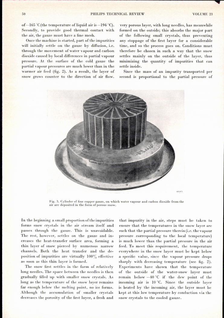
is a cylinder of fine copper gauze (fig. 3) kept at lowtemperature in a manner presently to be discussed.This "snow gauze" is surrounded by a doublejacket (the snow forms in the space between thejacket and the gauze). The air feed flows via thedouble jacket, in which it is precooled, to the snowspace, passes through the gauze andis then condensedon the head of the refrigerating machine. As theair flows through the gauze, a layer of snow formson its surface. The layer progressively thickens intoa snow cap, through which the air still has to pass.A "snow cake" from which a piece has been removedis shown in fig. 4. This cake took a week to grow toa thickness of about 10 cm; the innermost layer,about 0.5 cm thick, consists of carbon-dioxide snow.The density of the snow is fairly high, the valuesmeasured being 0.4 gfcm3 for the water snow and0.9 gfcm3 for the carbon-dioxide snow. Nevertheless,the layer is still porous, and the pressure dropacross it when the machine is working at fullcapacity is no more than 20 cm water column.What are the conditions to he fulfilled in order
to keep the snow layer porous? To answer thisquestion we must have a clear picture of the wayin which the layer of snow is formed.
Formation of the snow layer
, As long as no snow has yet formed on its surface,. relatively warm air enters into contact with thegauze. To prevent the transport of the fairlylarge amount of moisture still present in the airfeed, the gauze must he capable of cooling the airto a very low temperature. First of all, then, thegauze itself must he kept at the very lowtemperature
2) Dutch Patent No. 98 130.
50 PHILIPS TECHNICAL REVIEW VOLUME 23
of-165°C (the temperature of liquid air is-194 DC).Secondly, to provide good thermal contact withthe air, the gauze must have a fine mesh.
Once the machine is started, part of the impuritieswill initially settle on the gauze by diffusion, i.e.through the movement ofwater vapour and carbondioxide caused by local differences in partial vapourpressure. At the surface of the cold gauze thepartial vapour pressures are much lower than in thewarmer air feed (fig. 2). As a result, the layer ofsnow grows counter to the direction of air flow.
very porous layer, with long needles, has meanwhileformed on the outside; this absorbs the major partof the following small crystals, thus preventingany stoppage of the first layer for a considerabletime, and so the process goes on. Conditions musttherefore be chosen in such a way that the snowsettles mainly on the outside of the layer, thusminimizing the quantity of impurities that cansettle inside.Since the mass of an impurity transported per
second is proportional to the partial pressure of
4945
Fig. 3. Cylinder of fine copper ganze, on which water vapour and carbon dioxide from theair are deposited in the form ofporons snow.
In the beginning a small proportion of the impuritiesforms snow crystals in the air stream itself andpasses through the gauze. This is unavoidable.The rest, however, settles on the gauze and in-creases the heat-transfer surface area, forming athin layer of snow pierced by numerous narrowchannels. Both the heat transfer and the de-position of impurities are virtually 100% effectiveas soon as this thin layer is formed.The snow first settles in the form of relatively
long needles. The space between the needles is thengradually filled up with smaller snow crystals. Aslong as the temperature of the snow layer remainsfar enough below the melting point, no ice forms.Although the accumulation of smaller crystalsdecreases the porosity of the first layer, a fresh and
that impurity in the air, steps must be taken toensure that the temperatures in the snow layer aresuch that the partial pressure therein (i.e. the vapourpressure. corresponding to the local temperature)is much lower than the partial pressure in the airfeed. To meet this requirement, the temperatureeverywhere in the snow layer must be kept belowa specific value, since the vapour pressure dropssharply with decreasing temperature (see fig. 2).Experiments have shown that the temperatureof the outside of the water-snow layer mustremain below -40 DC if the dew point of theincoming air is 10 DC. Since the outside layeris heated by the incoming air, the layer must bekept at this low temperature by conduction via thesnow crystals to the cooled gauze.

1961/62, No. 2 A SNOW SEPARATOR
Fig. 4. A porous snow cake, about 10 cm thick, grown on the gauze in about a week.
Where the surface temperature of the snow layeris -40 DC, 99% of the moisture in the air feed willsettle on the outside, and only 1% will enter thelayer as vapour and form snow further inside wherethe temperature is lower (see fig. 2). Where thetemperature inside the layer is lower than -143 DC,the carbon dioxide also forms snow. In order toensure adequate trapping of the carbon dioxide,the temperature of the gauze should not exceed-165 DC. At this temperature 1% of the carbondioxide in the air feed is still transmitted; this hasbeen found to be a tolerable percentage.With the first designs of the snow separator, the
moment at which the machine had to be stopped fordefrosting because of excessive resistance to air flowwas determined by the amount of carbon dioxide inthe layer of water snow. An important improvementwas later introduced by surrounding the cylindricalsnow gauze (fig. 1) with a layer of metal gauzefolded in zigzag form roughly 12 mm thick (fig. 5).The water snow then forms on the outside of this"concertina gauze", whilst the carbon-dioxide snowhas ample space to settle inside it. This substantiallypostpones the moment at which the resistance toflow becomes excessive.
In the foregoing we have referred to the tempera-ture of the snow gauze, as if this temperature were
everywhere the same. This is not so, however. Heatis supplied to the gauze over its entire surface, andmust flow by conduction through the wires to theplaces where the gauze is brazed to cooled stripsor pipes (these structural details are indicated in thefigures at the end of the article). Midway betweenthe brazed joints the gauze is therefore not so cold.Evidently, the temperature differences in the gauzemust be small if the temperature at all points is to bekept below -165 DC, in other words the gauze mustbe a good heat conductor. Simple calculations andexperiments have shown that the only suitablematerial for the gauze is copper wire, which mustnot be too fine.
2
I I tI f, /1, A lVI1 A AI I 1\ \\ I1 /, /, / I / II /: /J ti I
I ,\ '\ I1 I \ I \ / , / \ / \ I I I I I/ // // /J II 1\ ,\ \ I \ \ \ I \I " \I \ 11 / I / / / / I /1 /1 I
, I' ,\ \ I \ 1\ \ \ 11 \I 11 \I Ill/It 1/ I/ 1/ 1 / / 17 /, III \\ \ \ \ \\ \1 \._.l_.l_.l_lTL1_l_.l /1 11 /1/ // ~/\' I, 1 \ \ \\ l. l.- 1 - .1_.1 // I / , I,I', I \ \ \\ ~_ - -.1 I / I1\'(\ \\_~- -.1_.[: 12mm""\ ).- ,..-).- <.
/ ,/ 520.5 "
Fig. 5. A layer of "concertina gauze" 2, about 12 mm thick, isfitted around the snow gauze 1. This promotes the depositionof water snow on the outside of the layer, and offers morespace for carbon-dioxide snow to settle.
51

52 PHILIPS TECHNICAL REVIEW
Another initial difficulty was that if the air feedentered the snow space through a small aperture,and thus at such a high velocity that turbulencesarose, the snow layer very soon became impene-trably dense. We can explain this as follows. Theeddying air is strongly cooled by the surface of thesnow, giving rise to hard snow crystals that show notendency to settle to form the porous layer required.Snow of. this structure, called "polar snow",evidently fills up the fine channels completely,causing a sharp increase in the air-flow resistance.If the air is allowed to enter the snow space througha large aperture, and thus at lower velocity, nodifficulties are experienced. Although the largetemperature differences existing might he expectedto cause convection currents in the air, thesecurrents (if they exist) are not troublesome.
The thermodynamics of the snow separator
We shall now consider the thermodynamics ofthe snow separator, with special reference to themagnitude of the air flow which can be handled.For this purpose we make the following simplifyingassumptions.1) The temperature of the air and that of the snow
are everywhere equal, i.e. there is infinitely goodthermal contact.
2) The' entire latent heat of sublimation of theimpurities and the heat absorbed while coolingthe air feed to the temperature of the outersurface of the snow layer are released at thesurface (in reality this heat is released in alayer a few millimetres thick).
3) Since, in accordance with assumption (2), thelatent heat of sublimation of the small quantityof impurities deposited in the snow layer isdisregarded, the enthalpy H of the air insidethe layer must be a linear function of thetemperature T. The rate of change' of theenthalpy with temperature is equal to thespecific heat cp of air at constant pre~sure:
en.dT = cp'
The variation of the enthalpy H of the air withtemperature T is shown in fig. 6. (Since the en-thalpy of a gas is determined but for an additiveconstant, whichwe can choose at our convenience,we are at liberty to assume the enthalpy of theair feed (at 10 oe, 1 atm) to be zero. Thissimplifies the calculations given below.)
4) The thermal conductivity À of the snow isassumed to he identical and constant at all
f
)i
VOLUME 23
o -------------------------------------------
H.-205 J/g -.!.---
-T-40-165
Fig. 6. Enthalpy II of air as a function of temperatm.:e T. Theenthalpy of the ambient air is assumed to be zero.
points (in reality À depends on the temperatureand density of the snow, and also on its struc-ture).
5) Although the snow gauze and the outside of thecake of snow have the form of coaxial cylinders,we shall regard them as parallel flat surfaces.A cylindrical section through the snow layer ata distance x from the gauze then becomes a flatsurface whose area A in fact depends on x.We will assume however that this area is constantand equal to the average of the surface area ofthe gauze and that of the cake of snow.In the steady state, the total heat flow through
every cross-section of the layer is constant. It mayeasily be sho~ that 'it follows from assumption(3) that the magnitude of this heat flow is in factzero. (This brings out the rather artificial nature ofassumption (3), since one normally regards the heat'content of a body as being positive, but this in noway detracts from the validity and utility of theassumption.) The total heat flow consists of anenthalpy flow in the air and a heat flow conductedby the snow. The enthalpy flow is equal to mH,where m is the mass of air displaced per second, andthe heat flowthrough the snow is equal to -ÀAdT/dx.We may therefore write:
(1)
dTmH-ÀA- = O.
dx
1961/62, No. 2 A SNOW SEPARATOR 53
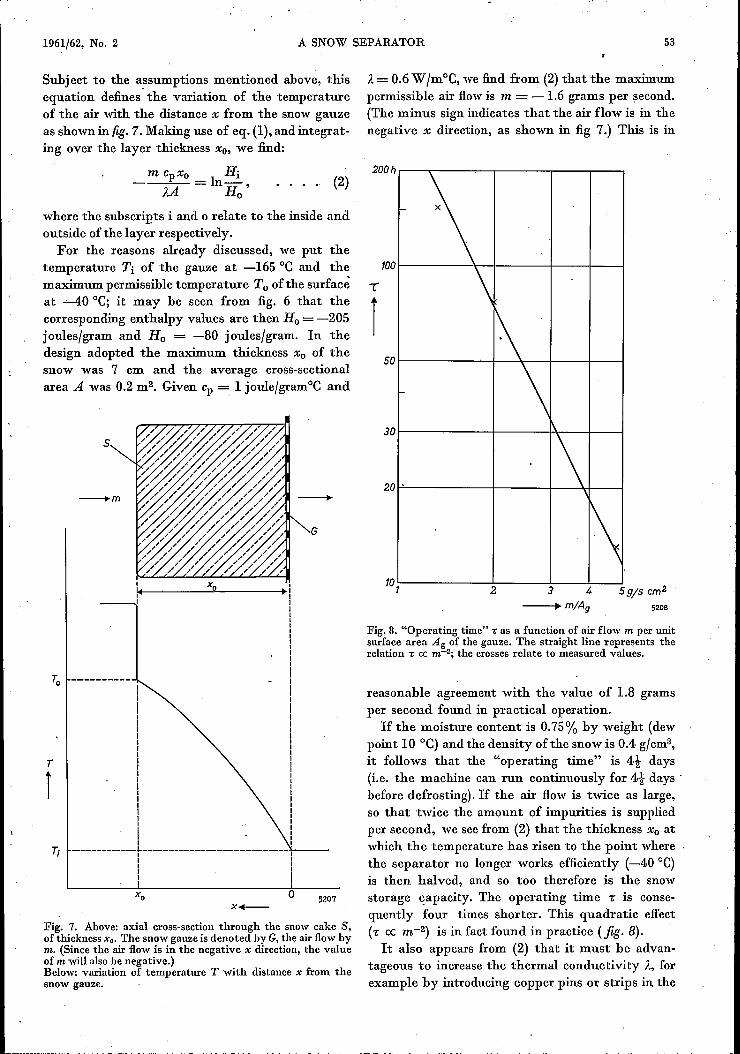
Subj eet to the a~sumptions mentioned above, thisequation defines the variation of the temperatureof the air with the distance x from the snow gauzeas shown in fig. 7. Making use of eq. (1), andintegrat-ing over the layer thickness xo, we find:
m cp Xo = InHi ,U Ho
where the subscripts i and 0 relate to the inside andoutside of the layer respectively.
For the reasons already discussed, we put thetemperature Ti of the gauze at -165°C and themaximum permissible temperature To of the surfacèat -40 °C; it may be seen from fig. 6 that thecorresponding enthalpy values are then Ho= -205joules/gram and Ho = -80 joules/gram. In thedesign adopted the maximum thickness Xo of thesnow was 7 cm and the average cross-sectionalarea A was 0.2 m2• Given cp . 1 joule/gramOC and
5
To ----------
T
ÎI
Ti -------------t----------------------------r---IIIII
o 5207x~
Fig. 7. Above: axial cross-section through the snow cake S,of thickness xo. The snow gauze is denoted by G, the air Howbym. (Since the air How is in the negative x direction, the valueof m will also be negative.)Below: variation of temperature T with distance x from thesnow gauze.
A = 0.6 W /moC, we find from (2) that the maximumpermissible air flow is m = - 1.6 grams per second.(The minus sign indicates that the air flow is in thenegative x direction, as shown in fig 7.) This is in
200h
l- x
\\\
r\
. \\
~
(2)
100
T
r50
30
20
2 59/5 cm25208
Fig. 8. "Operating time" 7: as a function of air flow m per unitsurface area Ag of the gauze. The straight line represents therelation 7: ex: m-2; the crosses relate to measured values.
reasonable agreement with the value of 1.8 gramsper second found in practical operation.If the moisture content is 0.75% by weight (dew
point 10°C) and the density ofthc snow is 0.4 g/cm3,
it follows that the "operating time" is 4t days(i.e. the machine can run continuously for 4t days'before defrosting). If the air flow is twice as large,so that twice the amount of impurities is suppliedper second, we see from (2) that the thickness Xo atwhich the temperature has risen to the point wherethe separator no longer works efficiently (-40°C)is then halved, and so too therefore is the snowstorage capacity, The operating time .. is conse-quently four times shorter. This quadratic effect(-r ex: m-2) is in fact found in practice (fig. 8).It also appears from (2) that it must be advan-
tageous to increase the thermal conductivity A, forexample by introducing copper pins or strips in the

54 PHILlPS TECHNICAL REVIEW
Fig. 11
4'94 b
Fig. 9
VOLUME 23
Fig. 10
Fig. 9. In the gas refrigerating machine the snow gauze is brazed to the radial coppergrid illustrated here, which is bolted to the cold head of the machine and thence dissipatesthe heat directly.
Fig. 10. In air-fractionating installations for producing liquid nitrogen, the snow gauze(here partly removed) is brazed to a crown of copper pipes, through which liquid oxygenof about -180°C flows.
Fig. 11. Air-fractionating colnmn (without refrigerating machine) for supplying liquidnitrogen 3). The bottom, dark section is an insulating jacket. in which the structureshown in fig. 10 islocated.
snow. The concertina gauze mentioned above also works along these lines.Finally, the snow separator as used in a liquid-air machine and in an
air-fractionating column 3) is illustrated in fig. 9, 10 anel 11. Variousstructural details are mentioned in the captions.
3) J. van der Ster and J. W. L. Köhler, A small air fractionating column used with agas refrigerating machine for producing liquid nitrogen, Philips tech. Rev. 20,177-187, 1958/59.J. van der Ster, The production of liquid nitrogen from atmospheric air using a gasrefrigerating machine, thesis, Delft 1960.
Summary. Before liquefying air, it is necessary to remove the moisture and carbondioxide it contains. Until recently, the Philips gas refrigerating machine used a sepa-rator on which these impurities settled in the form of ice and snow. A drawback of thisseparator was that it had to be defrosted once a day. An entirely new design ofseparator is discussed here, consisting of a cylindrical jacket of copper gauze, which iskept at a temperature of -165 oe and through which the air feed is passed. Water vapourand carbon dioxide settle on the gauze as a layer of porous snow (hence the name "snowseparator"). The layer remains porous for days and causes no appreciable pressure drop.Defrosting is necessary only after a continuous production of 600 litres of liquid air(five times as much as before), i.e. once or twice a week. The snow separator is alsobeing used with advantage in air-fractionating systems.