a sequential methodology for integrated physical and simulation experiments daniele romano dept. of...
TRANSCRIPT

A Sequential Methodology for Integrated Physical and Simulation Experiments
Daniele Romano
Dept. of Mechanical Engineering, University of CagliariPiazza d’Armi, Cagliari, Italy
e-mail: [email protected]
DEMA 2008 Workshop
Cambridge, 11-15 August 2008
Isaac Newton Institute for Mathematical Sciences
joint with Alessandra Giovagnoli

The problem
Design or improve a physical system by combined use of physical and simulation experiments
Schematisation
Two-treatment sequential experiment
T0: physical experimentT1: simulation experiment
T1 T0 T1 T1… … T0 Stop
Stopping rule is an essential part of the approach
Additional task: design of the experiments at each stage (i.e. choice of doses in clinical trials)
Assumptions• Physical observations are more reliable (closer to reality)• Simulation runs cost less

Questions
1. Is this problem relevant to applications?
2. Has it already been investigated?
Partially in “Calibration of computer models” but the objective is different and sometimes field data are not designed (Kennedy and O’Hagan, 2001, Bayarri et al., 2007).Calibration could be part of the method.

Analogies with other statistical problems
1. George Box’s sequential experimentation (Box and Wilson, 1957). However, there are no simulation experiments in that methodology and experiments are decided based mainly on expert judgment.
2. Sample surveys by questionnaires. Information can be obtained directly or by proxy, and a main question is how many resources to allocate to direct observations and how many to proxy ones. We are not aware however of a sequential approach.
3. Computer models with different level of accuracy (Qian et al., 2004)
4. Sequential experiments in clinical trials

Two motivating applications
Design of a robotic device (Manuello et al., 2003)
Improvement of a manufacturing process (Masala et al. 2008)
Sequence of experiments is based on judgement

Climbing robot
M
PLC
PC con scheda di acquisizione dati
Controllore a logica programmabile interfacciato al PC
Elettrovalvola 3/2unistabile
Regolatore di flussounidirezionale
Potenziometro lineare a rotazione
Trasduttore di pressione
Riduttore di pressione
Compressore
Gruppo alimentatoristrumenti di misura
21 factors investigated
simulation model developed in Working Model

Computerexperiments
Expert reasoning
12
34
56
7
89
12
13
10
11
1415
16
Physicalexperiments
1718
113 runs
6 runs
1 run
74 runs
18 runs
4 runs
9 runs
9 runs
6 runs
Total runs: 212 Total runs: 28
88% 12%
Computer modelmodification
Extensive exploration
Feasibility check on the prototype
Optimization
Confirmation
Exploration of the feasible region
Note the efficient allotment of experimental effort

The robot can climb steadily with speed seven times higher than in the initial design configuration and virtually on any post surface (robustness) better design
We just built one physical prototype instead of tens to investigate on 21 factors cost saving
Computer exploration makes us discover that the robot can descend passively, by using gravity innovation
The comparison of physical vs numerical gave the designer the idea of how to modify the code improving the model simulation model improved
Benefits

0 0.417 0.45-400
-350
-300
-250
-200
-150
-100
-50
0
50evo 2
tempo [s]
Allu
ngam
ento
[m
m] fall
0 0.417 0.833 1.25 1.667-200
-180
-160
-140
-120
-100
-80
-60
-40
-20
0
20evo 8
tempo [s]
Allu
ngam
ento
[m
m]
no move
0 0.25 0.5 0.75 1
-200
-150
-100
-50
0
50evo 22
tempo [s]
Allu
ngam
ento
[m
m]
fall in controlclimb steadily
0 1 2-80
-60
-40
-20
0
20
40
tempo [s]
allu
ngam
ento
[mm
]
evo 3
innovation
0 0.2 0.4 0.6 0.8 1 1.2-800
-700
-600
-500
-400
-300
-200
-100
0
100evo 35
tempo [s]
Allu
ngam
ento
[m
m]
climb and then fall
operating modes of the robot

Improvement of the flocking process
threadflock
Car component covered by flock fabric
Flock yarns Two simulation models developed: one for the electric field inside the chamber (FEMLAB), one for the motion of the flock (MATLAB).
9 factors investigated

63% 37%
Simulation experiments Expert reasoning
12
34
56
7
12
9
10
13
11
Physical experiments
9 runs
11 runs
144 runs
Simulation runs: 153 (63%) Physical runs: 90 (37%)
Electric field simulator
Pilot plant
22 runs Pilot plant
Production line
22 runs
8 35 runs
Lab
Electric field simulator + flock motion simulator

Operating conditions considered potentially unsafe have been tried on the simulator, obtaining golden information for improving the process. These conditions would never have been tried in the field. process efficiency increases
Increased process efficiency can be exploited to raise productivity (up to 50%) ( process improvement) or to produce yarns with new characteristics product innovation
Results from physical and simulation experiments were used for tuning some unknown parameters of the simulator computer model calibration
A mechanistic model of the whole process was developed by combining the simulation models with the results of a physical experiment (determining the rate of lifted flock). new process design tool
Benefits

Response models
Reality
Physical trials
Simulation
)(R xy
)()( RP xx yy
)()()( RS xxx byy
are taken as response surfaces and are estimated by polynomial regression over the region of interest
SP yy and
(0,2) with independent errors,
b(x) is the bias function, estimated by )(ˆ)(ˆ PS xx yy
Locate a sufficiently high value of the true response over the domain D by using simulation as much as possible, provided that simulation is found reliable enough.
Objective
x D (a hyper-rectangle)

Sequential procedure
k=0: the experiment is physical Pk
k=1: the experiment is numerical Sk
At each step k of the procedure we must decide on:
the type of the experiment
the region where the experiment is run, Rk
the runs size, nk
the design, k
We make simple choices on the type of the region and the design throughout:
Rk is a hypercube of fixed size (centre Ck)
k is a Latin Hypercube Design
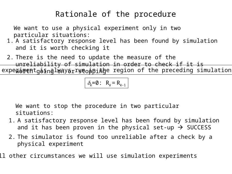
Rationale of the procedure
We want to use a physical experiment only in two particular situations:
1. A satisfactory response level has been found by simulation and it is worth checking it
2. There is the need to update the measure of the unreliability of simulation in order to check if it is worth going on or stopping
We want to stop the procedure in two particular situations:
1. A satisfactory response level has been found by simulation and it has been proven in the physical set-up SUCCESS
2. The simulator is found too unreliable after a check by a physical experiment
In all other circumstances we will use simulation experiments
A physical experiment is always run in the region of the preceding simulation experiment
k=0: Rk = Rk-1

Sk
Sk+1
Pk+1
S1 P2
Pk
Sk+1
Stop
Allowed transitions
START:
Sk Stop
Pk Pk+1

Performance measures at stage k
Satisfaction
Expected improvement in next simulation experiment
Total cost
)(ˆmax)(R
SAT xx
ykk
k
iPiiSiik cncnc
1
))1((
Increment in satisfaction wrt the last experiment of the same kind
DSATk) = SATk) - SATk-l*)
)(ˆ * xSmky
gradient
Rk
)(ˆmax)( *
0n̂ˆ
IMPR
*
xx
Smk
y
ykmk
k
n̂
kfrontier

Unreliability of the simulation(after Pk)
2
2
UNREL ˆ
/)(ˆ)(ˆ
)(k
RR
PS
kk
ddyy
k
xxxx
: error variance estimated at step k2ˆ k
jdm
Ck
k
j k
kj
m
1
i
iUNRELUNREL
)C,(d1)(ˆ
mk: number of regions where both kind of experiments were done up to step k
d : length of the hypercube edge
continued
Unreliability of the simulation(after Sk)

Sk
Sk+1
Pk
Pk
Sk+1
Stop
SAT(k)>sC or >uC
otherwise
or (r1,r2,r3,r4) = 1
How are transitions ruled?
otherwise
Satisfaction (after a physical experiment) is high
Simulation is too unreliable
r1: SAT(k)>sC
r2: UNREL(k)>uC
r3:
r4:
maxcck
0)(D) -(1max SAT0
k-ik-i
l
i Too many stages without any
actual improvement
Allowable cost exceeded
)(ˆUNREL k

k=1
S1
k=k+1
Pk
Check stopN
Y
STOP
k=k+1
Sk
Check S->PN
Y
High-level flow diagram of the procedure
Only high level decision is made explicit here

Block Sk or Pk
Select Rk,nk, k
Run k
Estimate y(x)
Compute performance measures SAT(k), DSAT(k), UNREL(k), IMPR(k), c(k)

Low-level decisions: select region, run size and design
k=0: Rk = Rk-1
k=1: Rk ≠ Rk-1
IMPR(k)>0NY
Compute Ck
(Rk adjacent to Rk-1)Draw Ck
at random
)(ˆ)(ˆ
)n̂)(ˆ(2 max*
max*max*max max x
xxx x
mk
mkmkk y
yy
dC
Region

A
B
D
R1=R2
R3
R4
R5
R6
C1= C2
C3
C4
C5
C6
sample space
x1
x2

nk = nk-1, = cS/cP , 0<<1
k=1:
Run size
Run size of each physical experiment is such that it costs as much as the simulation experiment preceding it
Run size of simulation experiments is proportional to the expected increase of the response (if any) at the centre, Ck, of the next region, i.e.,
)()C,( IMPRmax1 kdhcn ksk x
Parameter h can be tuned by setting the willingness to pay for obtaining an improvement y, for example
yhcnc Skk
)()C,( IMPRmax kd k x
When region Rk is drawn at random, we put nk= n1
k=0: Pk
k=1: Sk

A
B
D
R1=R2
R3
R4
R5
R6
C1=C2
C3
C4
C5
C6
sample space
x1
x2
+
+
+
+
++
+
+
++
+
+
+
+
+
+
+
+
+
+
+
+
+
+
+
+
+
+
+

Demonstrative case
A computer code for implementing the procedure has been developed in Matlab
-10 -5 0 5 10-120
-100
-80
-60
-40
-20
0
20
40
x
y
simulation
reality

-1 0 1 2 3 4 5 6 7 8 9-15
-10
-5
0
5
10
15
20
25
case 1
reality
* simulation experiment
prediction
* physical experimentprediction
R1= R2R3 R4= R5
sequence of experiments: S1P2S3S4P5Stopactive stopping rule: UNREL(k)>uC
2

-2 -1 0 1 2 3 4 5-15
-10
-5
0
5
10
15
20
case 2
reality
* simulation experiment
prediction
* physical experimentprediction
R1= R2 R3= R4
sequence of experiments: S1P2S3P4Stopactive stopping rule: SAT(4)>uS
3

-2 0 2 4 6 8 10-10
-5
0
5
10
15
20
25
30
R1= R2 R3 R4 = R5
reality
* simulation experiment
prediction
* physical experimentprediction
case 3
sequence of experiments: S1P2S3S4 P5 Stopactive stopping rule: SAT(5)>uS
simulation = reality
2

-8 -6 -4 -2 0 2 4 6 8 10-25
-20
-15
-10
-5
0
5
10
15
20
25
R1= R2 R3 R4 R5 R6 = R7
reality
* simulation experiment
prediction
* physical experimentprediction
case 4
sequence of experiments: S1P2S3S4 S5 S6 P7 Stopactive stopping rule: SAT(7)>uS
simulation = reality
2

Conclusions
The scope of the approach is wide. In general, it is apt to deal with any situation where the response can be measured by two (or more) instruments realizing a different quality-cost trade-off.
The method is aimed at performance optimisation (maximisation of a distance measure in the output space). However, the basic sequential mechanism can be applied to different goals.
Testing and validation in real applications is needed.

“The reader should notice the degree to which informed human judgement decides the final outcome”.
George Box, commenting on the sequential experimentation method:
Box, G. P. E., Hunter, W. G., Hunter, J. S. (1978): Statistics for experimenters, p. 537.
human judgement or automation?
Shall we ask Newton?

Kennedy, M.C., O’Hagan, A.: Bayesian calibration of computer models. Journal of the Royal Statistical Society: Series B, 63 Part 3, 425-464 (2001)
Qian, Z., Seepersad, C.C., Joseph, V.R., Allen, J.K., Wu, C.F.J.: Building Surrogate Models Based on Detailed and Approximate Simulations. ASME 30th Conf. of Design Automation, Salt Lake City, USA. Chen, W. (Ed.), ASME Paper no. DETC2004/DAC-57486 (2004)
Bayarri, M.J., Berger, J.O., Paulo, R., Sacks, J., Cafeo, J.A., Cavendish, J., Lin, C.-H., Tu, J.: A Framework for Validation of Computer Models, Technometrics, 49(2), 138-154 (2007)
Manuello, A., Romano, D., Ruggiu, M.: Development of a Pneumatic Climbing Robot by Computer Experiments. 12th Int. Workshop on Robotics in Alpe-Adria-Danube Region, Cassino, Italy. Ceccarelli, M. (Ed.), available on CD Rom (2003)
Masala, S., Pedone, P., Sandigliano, M. and Romano, D.: Improvement of a manufacturing process by integrated physical and simulation experiments: a case-study in the textile industry. Quality and Reliability Engineering Int., to appear
References
Box, G.E.P., Wilson, K.B.: On the Experimental Attainment of Optimum Conditions, Journal of the Royal Statistical Society: Series B, 13, 1-45 (1951)