a septic tank for farm homes - internet archive
TRANSCRIPT

CALIFORNIA AGRICULTURAL EXTENSION SERVICE
CIRCULAR 82 REVISED JANUARY 1949
AsEM^riOR
FARI*HOMES
H. L BELTON
AND
J. P. FAIRBANK
THE COLLEGE OF AGRICULTURE
UNIVERSITY OF CALIFORNIA BERKELEY
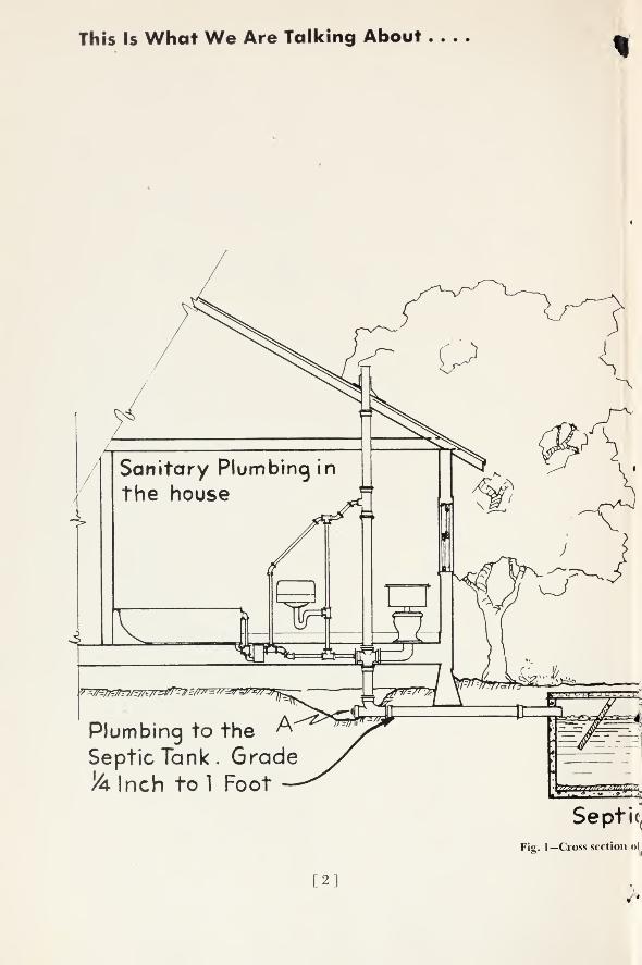
This Is What We Are Talking About
Plumbing to the
Septic Tank. Grade&lnch tol Foot
Septic(
Fig. 1—Cross section oi
2]

fank>he complete system.
Subsurface drainage system -
Wood or Concrete pipe a r». Grade
1 Inch in 20 Feet.
[3]

And This Is What You Will Need
MATERIALS REQUIRED
MATERIALS AMOUNT DOLLARS CENTS
CONCRETEMATERIALS
2 cubic yards crushed rock %-inch to 1-inch size.
l 1/^ cubic yards sand.
16 sacks cement.
(If crushed rock is not available, 3^2 cubic
yards of clean, well-graded gravel, suitable for
good concrete, may be substituted for the rock
and sand.)
1 vitrified single-branch Y sewer tile, size 4-inch.
Vitrified bell-neck sewer tile, size 4-inch.
(Amounts of sewer tile and drainage line not
given, as local conditions govern quantity re-
quired.)
2" x 10" and 2" x 12" heart common grade red-
wood or preservative-treated lumber, or half sec-
tion of 12-inch concrete pipe.
1% cubic feet of %-inch to 1%-inch rock for
each foot of drainage line.
1 pound 20d nails for each 25 feet of trough.
(Amounts of drainage line not given, as local
conditions govern quantity required.)
1 piece 2" x 10" x 14' rough common redwood or
cedar.
2 pieces 2" X 10" x 10' rough common redwood
or cedar.
(6-inch and 12-inch widths may be substituted
if 10-inch is not available.)
2 pieces 1" x 4" x 12'.
2 pieces 1" x 4" x 10'.
Side walls, 21 pieces 1" x 6" X 10'.
End walls and braces, 8 pieces 1" x 6" x 12'.
2 pieces 1" x 6" x 8'.
Hanging boards and boxes, 1 piece 1" x 6" x 12'.
Baffle cleats and corner strips, 3 pieces
1" x 3" x 12'.
Long and center studding, 2 pieces 2" x 4" x 14'.
3 pieces 2" x 4" x 10'.
Corner studding, 2 pieces 2" x 3" x 10'.
2 pounds 8d common wire nails.
2 pounds 6d box nails.
( )
TILE
DRAINAGE LINE
BAFFLE BOARDS
COVER FORMS (com-mon lumber surfaced
one side)
surfaced one side)
NAILS
TOTAL
Take This with You When Pricing or Ordering Materials
[4]

Our Purpose
is to tell you how to build a concrete
septic tank and drainage system for farm
homes.
This circular has been reviewed by the
State of California, Department of Public
Health, Bureau of Sanitary Engineering.
Although the details of the septic tank
described herein differ from those shown
in the Health Bureau's Bulletin 56A, the
design complies with the general prin-
ciples; but the capacity, which is the
most important feature, is the same.
If you decide to build the septic tank
and sewerage system described in this
circular it is imperative that you check
county ordinances first.Do not proceed
with any type of installation until you
have checked with your county health
department.
THE AUTHORS:
H. L. Belton is Associate in Agricultural Engineering and Asso-ciate in the Experiment Station.
J. P. Fairbank is Lecturer and Associate Agricultural Engineerin the Experiment Station.
[5]

Nearly three fourths of the farms in California have piped water into the house.
There is little advantage to this unless it is combined with an adequate sewage dis-
posal system. This system must be safe and operate effectively.
The combination of a septic tank and a subsurface drainage system is a satisfactory
method of sewage disposal for most farm homes.
What about Leaching Cesspools?
The combination of a septic tank anda subsurface drainage system is generally
safer than a leaching cesspool for absorb-
ing sewage.
A leaching cesspool may be used, how-
ever, where the top soil is impervious to
water, yet layers of sand and loam are
under the top soil.
A leaching cesspool should never be
used if there is a danger of contaminat-
ing wells or springs.
What Is a Septic Tank?
A septic tank is only one unit of a
complete sewage disposal system. Other
important parts are:
Sanitary plumbing in the house.
Plumbing to the septic tank.
The subsurface drainage system.
The above are shown in figure 1.
All sewage and waste water from the
house plumbing fixtures flow into the
septic tank.
A septic tank is a watertight container.
The chief function of the tank is to
serve as a settling basin wherein the solids
settle out of the liquids much as mud set-
tles out of water.
Bacterial action starts shortly after the
solids have settled. It breaks down the
coarse material and reduces the volumeof solid matter.
The partly clarified but still impureliquid "effluent" passes out of the tank
through an outlet near its top and into
the drainage system.
When once in the drainage system the
effluent filters into the soil.
A Common Cause of Stoppage
Some finely divided particles of sew-
age are carried out with the effluent.
Some settle to the bottom of the tank.
In time those which settle to the bottomof the tank accumulate to a considerable
depth. When this happens the finely di-
vided particles of sewage pass out of the
tank at an increased rate.
This causes stoppage in the drainage
system.
Cleaning the Septic Tank
A septic tank must be cleaned out at
intervals.
Frequency depends on the size of the
tank and the amount of sewage.
Depth of sludge in the bottom of the
tank—not the scum or mat which usually
forms on the liquid surface—determines
the need for cleaning.
CAUTION
Although the water entering the drain-
age system is almost clear, it is not purewater.
It must not be allowed to enter wells
or other sources of domestic water supply.
Final purification takes place in the
upper layer of soil both by filtering andbacterial action.
The effluent, when exposed to the openair as in ditches or pools, will give off
foul odors. It will also be a source of con-
tamination that may be carried by insects
or animals.
Typhoid stools and other infectious
matter should be disinfected before dis-
posal through toilets.
[6]
TYPE OF TANKThe tank must be large enough, water-
tight, adequately baffled, accessible for
cleaning, and constructed of materials
which do not quickly decay or rust.
Simplicity of construction is desirable,
but some form of baffling should be used
to minimize agitation of the tank's con-
tents and reduce the escape of solids
through the tank outlet.
Ready-built septic tanks of different
types and sizes are manufactured com-mercially and sold ready to install. Theyare made of steel, of wood, and of large-
sized concrete pipe or vitrified clay pipe.
In general, they have proved satisfactory
when of adequate size and correctly in-
stalled. Their most common fault is lack
of capacity.
The purchaser should be sure to select
a size suitable for his needs.
Check County and Local Ordinances
Persons who plan to build septic tanks
in counties which have ordinances gov-
erning septic tank design, capacity andinstallation should first confer with their
County Health Department before pro-
ceeding with construction.
The septic tank described in this cir-
cular is larger but similar in design to
the type of tank recommended by the
University of California since 1917.
Thousands of these tanks have given sat-
isfactory service.
The sizes meet the recommendationsof the California State Department of
Public Health, Bureau of Sanitary Engi-
neering, as outlined in their Special Bul-
letin 56A, which is used generally as a
standard by the County Health officers
for approval for FHA and VA loans.
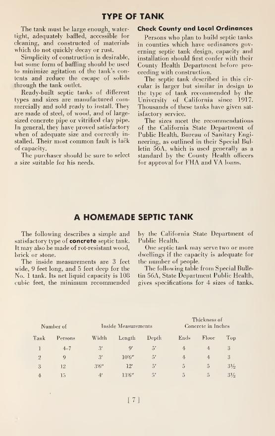
A HOMEMADE SEPTIC TANK
The following describes a simple andsatisfactory type of concrete septic tank.
It may also be made of rot-resistant wood,brick or stone.
The inside measurements are 3 feet
wide, 9 feet long, and 5 feet deep for the
No. 1 tank. Its net liquid capacity is 108
cubic feet, the minimum recommended
by the California State Department of
Public Health.
One septic tank may serve two or moredwellings if the capacity is adequate for
the number of people.
The following table from Special Bulle-
tin 56A, State Department Public Health,
gives specifications for 4 sizes of tanks.
Thickness of
Number of Inside Measurements Concrete in Inches
Tank Persons Width Length Depth Ends Floor Top
1 4-7 3' 9' 5' 4 4 3
2 9 3' 10'6" 5' 4 4 3
3 12 3'6" 12' 5' 5 5 3V2
4 15 4' 13'6" 5' 5 5 3%
[7]

This Is One Unit of the System .... A Half-
Section View of the Concrete Septic Tank
Inlet.
Fig. 2 —Half-section view of septic tank.
And
The Side View of the Tank.
This Size Is For Not MoreThan Seven Persons
[8]

TANK LOCATIONThe septic tank is normally located not
farther than 50 feet from the house, but
in some instances it may he as close as 10
feet.
The tank should not be placed undera foundation, permanent walk, or drive-
way. This might prevent its being uncov-
ered for cleaning.
The tank is usually constructed so that
the cover is flush with the ground or
slightly lower. Accordingly, the top of the
tank outlet line will be 12 to 16 inches
below the ground level. This depth has
proved satisfactory when favorable soil
conditions for drainage exist.
A high water table at certain seasons,
heavy clay loam, or hardpan near the sur-
face may make it advisable to keep the
top of the tank above ground level to pro-
vide a drainage outlet near the surface.
The Fall, or Grade, of the SewerPipe Line Is Important
The fall of the sewer pipe from the
house plumbing fixtures into the tank
should be not less than % inch to the foot,
which is 12% inches in 50 feet. The fall
must be taken into consideration whenchoosing a location for the tank.
If the tank is located a considerable
distance from the house and the groundis level, the tank must be placed deep
enough to provide sufficient fall for the
sewer line. This means a deeper drainage
system which, in general, is undesirable
and more costly.
The Drainage Line out of the Tank
The grade for the drainage line need
not be more than 1 inch in 20 feet, which
is 2% inches in 50 feet. Therefore, the
use of a sufficient length of vitrified sewer
pipe with cemented joints from the septic
tank to the distribution lines makes it pos-
sible to:
Locate the tank near the house.
Permit installation of the drainage area
nearer to the ground surface.
Provide a method whereby the drain-
age area may be located at a safe dis-
tance from a well or spring.
The sewer pipe may enter the tank oneither side of the center in the end wall
if that placing is more convenient.
ReinforcementVz" round rods or heovv hog ^fencing
EiI^EgS5J£gInlet4" Vit. ti
1&2 JK
Voter levely^
2"* 10" Redvood Planks
9-0"
\^A vTZT
Fig. 3—Half-section side view of septic tank.
[9]

This Is the Wooden Form You Will Have To Build .
.
Fig. 4—Wooden form for concrete septic tank.
Build it carefully • . . pay close attention to construction details.
You will avoid trouble later.
The above drawing is also reproduced on page 23. Cut it out
for ready reference while reading or building the form.
[10

DIRECTIONS FOR BUILDING
The following directions apply to the No. 1 tank for a family up to 7 persons.
For larger tanks, the dimensions should be increased in accordance with sizes given
in the foregoing table.
Preparing for Excavation
After choosing the tank location makea rectangular frame. Two planks 3 feet
8 inches apart should be laid level andheld in a flat position against stakes
driven into the ground (fig. 5).
Nail two 1x6 inch boards across the
planks to form a rectangular frame with
inside dimensions of 9 feet 8 inches by 3
feet 8 inches.
This frame about the top of the hole
prevents earth crumbling on the freshly
poured concrete during construction. It
also provides a working edge from which
a plumb bob may be suspended to aid in
digging perpendicular walls.
If the earth is such that it might cave
in, the hole must be made larger to ac-
commodate an outside form.
Under ordinary conditions the hole is
dug to a depth between 5 feet 7 inches and6 feet below the bottom of the frame. This
places the tank cover to 5 inches, and
the top of the outlet pipe 11 to 16 inches,
below the surface.
Local conditions, however, determine
the depth of the tank.
The Forms
Forms are designed so that they can be
easily removed in sections without dam-age.
They may be used repeatedly.
Many farm centers own sets of forms
which they rent at a nominal charge to
pay for the lumber and minor repairs.
Sets have been used twenty to thirty
times.
Forms should be made of commonlumber surfaced on one side. They should
be oiled before use. This adds to their life
and prevents concrete from sticking to
the wood.Figure 4 gives the dimensions for con-
structing the inside form.
Outside measurements should corre-
spond to the inside measurements of the
tank.
•. >;,,,,-....,,,..:,.,.,:;.,,:;.:. ::,;
Fig. 5 — Rectangularframe about the hole. The2xl0-inch planks arelater used as baffle boards.
ii]

BUILDING
Side Panels
See figure 4. The sheathing, which may be 1 x 6 inches, is nailed firmly to the 2x4-inch studding—A and D.
The 1 x 2-inch baffle cleats—F—are then nailed on the side of the panels as grooves
for the baffle boards. The cleats should be slightly beveled on the edges to insure easy
removal of the side panels.
Figures 6 through 9 also show the construction.
Fig. 6—Squaring up and starting the side-wall form.
Fig. 7—The side-wall sheathing should be well nailed,
and the boards drawn close together.
[12]

Fig. 8—Nail the 1 x 2-inch baffle cleats firmly in position
after trimming the side-wall sheathing.
Fig. 9—Assemblingside-wall forms andplacing the 1 x 6-inch
cross ties in the properposition.
[13

Cross Braces
See figure 4. Ten 1 x 6-inch cross
braces—E—five above and five below,
hold the side panels to the proper width.
The five bottom braces should be 6
inches above the bottom of the form.
End Panels
See figures 4 and 10. The end panels,
constructed as shown in figure 10. are
held to the 2 x 3-inch studding—B—whichfits against the studding—A—and the end
of the side wall sheathing.
Two 8d common nails—C—at each cor-
ner hold the studding—B—in proper po-
sition.
Four 6d nails are enough to hold the
end panel to the studding—B.
Corner Strips
See figure 4.
The corner strips—G—are held to the
studding—B—by one small nail each,
tacked near the top. These nails should
be pulled out before the concrete is
poured above them.
Hanging the Form
See figures 4 and 11.
As an aid to setting the form in posi-
tion, the studding—A—should project 2
feet above the top edge of the wall sheath-
ing. After being lowered into the hole,
the form should be blocked up level to
allow for a 4-inch bottom of concrete, and
squared up in the hole so that all walls
will be of the same thickness.
See figure 12.
Next, 1 x 6-inch hanging boards should
be nailed firmly to the 2x4 studding—
A—and to the 2 x 10-inch plank frame
that was first placed about the top edges
of the hole.
The blocking used to allow for a 4-inch
bottom of concrete can now be removed,and the form is ready for the concrete.
Vidth of end panels is 36"
minus tvice the vidthof corner strip "G"
Fig. 10—End panel. Four 6d nails, one at
each corner, hold the end panels to the 2x3-inch studding B, figure 4.
Fig. 11—The completed form being loweredinto the hole.
[14

2*10" baffle-board
r^n
Fig. 12—End view of the
completed form suspendedin the hole.
I x 6"
1 Vru.fc>
CONSTRUCTION OF TANK
The tank should have 4-inch sides anda 4-inch bottom.
The top must be 3 inches thick and re-
inforced.
The Concrete Mix
A 1 : 2^4 '• 3 concrete mixture is recom-mended. This means
:
1 : 1 sack or 1 cubic foot of cement.
2 1/4 : 2 1
/4 cubic feet of sand.
3 : 3 cubic feet of crushed rock.
Both the sand and the rock should beclean and free from organic matter.
The sand should vary from fine to %inch in size.
The rock should vary from % to %inch.
Clean, well-graded gravel may be sub-
stituted for the rock and sand. This mixcalls for 1 sack of cement to 41
/i> cubic
feet of gravel.
The Amount of Water Used
Enough water should be added to the
dry mix to give the entire mixture a plas-
tic consistency.
Too much water is bad. It reduces the
strength of the concrete.
Use only enough water to make a work-
able mixture.
Pouring the Concrete
Tamp the concrete thoroughly while it
is being poured. This will insure smoothwatertight walls.
A 1 x 2-inch strip of lumber with a
V-shaped point makes a good tamp for
working the concrete into place.
CAUTIONDon't crowd the forms out of alignment
by pouring too much concrete in oneplace.
[15]

Placing the Inlet and Outlet Boxes
See figure 4.
When the concrete is within 11 inches
of the top at the inlet end of the tank
form, and 14 inches at the outlet end,
place the 6 x 6 x 4-inch boxes in their
proper positions against the form.
Small nails driven into the form before
it is lowered into the hole will help to lo-
cate the exact position of these boxes.
When the boxes are in position, con-
tinue pouring the walls.
True the top edge of the form with a
trowel or block.
Pouring the Concrete Tank Floor
Since the walls are poured first, someconcrete will work out from under the
wall forms and spread over the bottom of
the hole. This concrete should be tampedand smoothed into place along with the
tank floor which is poured immediatelyafter the walls.
The concrete floor should not extend
any higher than the bottom of the forms.
If it does it will make the forms difficult
to remove later.
Constructing the Tank Cover
See figure 13.
Concrete slabs are used for the tank
cover.
Level off some nearby ground as a workarea for building a form.
Cut two 1 x 4-inch boards into lengths
of 10 feet. Stake them on edge parallel
to one another. They should be 3 feet 8
inches apart.
Cut the crosspieces. These should be
1 x 4's in lengths of 3 feet 8 inches.
Nail the crosspieces into position to
form five rectangular compartments with
inside dimensions 23 inches by 3 feet 8
inches.
Fill the bottoms of these compartmentswith fine damp earth or with sand.
Smooth to a level surface.
Leave 3 inches for the concrete.
Pour %: mcn °f concrete into the com-partments over the earth or sand.
Immediately place the reinforcing in
each compartment. This may be heavyhog fencing or three %-inch steel rods.
Continue pouring the concrete until the
compartments are filled.
ReinforcementVz" f rods or heavy^,
hog fenci
Fig. 13—Form for cover slabs.
[16]

Leave smooth and level with the top
edge of the form.
Removing the Tank Forms
See figure 4.
After the concrete has taken its initial
set, which is usually within 1 hour, the
1 x 2-inch strips—G—at the far corners
may be tapped lightly with a hammerand drawn out. Their removal tends to
prevent cracking of the concrete at the
corners.
When the concrete has set 16 to 24
hours, the forms may be taken out in this
order.
1. The 1 x 6-inch hanging boards
shown in figure 12.
2. The cross braces—E.
3. The 2 x 3-inch corner studding—B.
Take off by prying them inward after re-
moving nails—C.
4. The end panels.
5. The side panels. These may be lifted
out intact. Care should be taken not to
break the concrete around the edges of
the grooves into which the baffle boards
are to be inserted.
6. The 6 x 6 x 4-inch boxes.
Curing the Concrete
The concrete should not be allowed to
dry rapidly.
After the concrete has taken its initial
set (usually within 1 hour) the exposed
surfaces may be covered with wet sacks
until the forms are taken out (usually 16
to 24 hours for the tank)
.
The tank should be kept wet for several
days after the forms have been removed.
The cover slabs may be protected with
wet sacks for a few hours and then kept
wet for one week by flooding or using wet
earth.
Completing the Tank
See figure 2.
Any porous areas in the concrete
should be pointed up with a mortar madeof equal parts of fine sand and cement.
The outlet Y branch should be inserted
into position as shown. Use sand-cement
mortar to secure a watertight joint in the
wall.
[
The upper branch of the Y should be
plugged with mortar, except for a small
vent at the top.
The 2 x 10-inch baffle boards should be
fitted loosely in the grooves.
Apply a small amount of mortar in the
grooves at the ends of the top baffle
boards. This will stop them from floating
when the tank is filled with sewage.
The inlet pipe from the house projects
2 inches into the tank. It should be mor-
tared in place.
The cover slabs may be placed in posi-
tion after the concrete has been cured for
at least one week. Install these so that the
reinforcing steel is near the bottom.
Unless the tank is covered with several
inches of dirt, the cover slabs should be
sealed with a lean mortar so that they maybe taken off more easily.
A lean mortar is a mixture of 1 part
cement to 6 parts of sand.
Connecting the Tank
The pipe leading from the house to the
septic tank should be laid to a grade of
not less than % inch to the foot. It should
be embedded firmly in the ground.
Cast-iron pipe with tightly caulked
joints is recommended, but vitrified clay
or other approved sewer pipe may be used
between the house foundation and the
tank.
To clean out any mortar which might
be in the line and obstruct the inflowing
sewage, a swab made from a piece of bur-
lap and a stick should be run through
each length of pipe after the joint is ce-
mented.
The plumbing fixtures and sewer line
should be installed in accordance with
standard sanitary plumbing practice.
CAUTIONThe sewer pipe at the point of
leaving the house should be kept as
high as possible so that the sewer
line Teading from the house to the
tank may be kept as near to the
ground surface as possible. This
avoids having to bury the tank too
deeply.
17]

It is not necessary to have a trap in the
sewer line between the house and the
tank, nor a vent in the septic tank.
A clean-out plug shown at A in figure
1 is recommended.
Mosquito Control
Vent stacks should be capped or
plugged with 16-mesh copper screen cloth.
Tar paper or composition roofing
should be laid over the cover slabs of the
tank before earth is backfilled on the com-
pleted tank.
It has been found that plumbing vent
stacks, and cracks in the backfilled earth
over improperly sealed septic tank covers,
have been places through which mosqui-
toes enter the tank and lay their eggs.
FINAL DISPOSAL OF THE EFFLUENT
Safe and trouble-free disposal of the
effluent from the tank is of prime impor-
tance.
The following suggestions and recom-
mendations are made in collaboration
with the Bureau of Sanitary Engineering,
California State Department of Public
Health.
The means for the final disposal of the
effluent depend upon local conditions.
The effluent must not be allowed to
flow on the top of the ground, into open
ditches or streams, nor within 75 feet of
wells or springs. If the subsurface soil is
waterlogged, then a distance of at least
200 feet from wells and springs is recom-
mended.
There Are State Laws Governing
Sewage Disposal—Violation
Carries Heavy Penalties
State law forbids the disposal of sew-
age into deep drains or "sewer wells," or
deep cesspools which reach to water strata
that may be used, or that even are usable
for domestic purposes. Violation of this
law carries heavy penalties. Its purpose
is to preserve the purity of underground
water supplies, not merely for the present,
but for the future as well. Nowhere is this
more important than in the country.
In general, the recommended disposal
of the effluent from septic tanks is by un-
derground trenches. The drainage lines
may be under lawns or among shrubs or
trees. This serves as subirrigation.
The use of the sewage water by vege-
tation helps to prevent waterlogging,
BUT the regulations of the State Board
[18
of Health forbid the use of sewage water
to irrigate vegetables or edible berries.
The text of the regulations is as fol-
lows:
Rule 3. Settled or Undisinfected Sew-age Effluents.
Effluents of septic tanks, Imhoff tanks
or of other settling tanks, or partially
disinfected effluents of sprinkling
filters or activated sludge plants or
similar sewages, shall not be used to
water any growing vegetables, gar-
den truck, berries, or low-growing
fruits such that the fruit is in contact
with the ground, or to water vine-
yards or orchard crops during sea-
sons in which the windfalls or fruit lie
on the ground. Such sewage, efflu-
ents, or any sludge or screenings
shall not be permitted in ditches or
pipes which may be used to irrigate
vegetables, garden truck, berries, or
low-growing fruit.
However, such sewage may beused for irrigating growing vege-
tables grown exclusively for seedpurposes in fields where crops are
raised and watered not in conflict
with this rule.
Nursery stock, cotton, and such
field crops as hay, grain, rice, al-
falfa, sugar beets, fodder corn, cow-beets, and fodder carrots may bewatered with such settled or undisin-
fected or partially disinfected sew-
age effluents provided that no milch
cows are pastured on the land while
it is moist with sewage, or have ac-
cess to ditches carrying such sewage.

THE SEWER LINE FOR THE SUBSURFACE
DRAINAGE SYSTEMSee figures 14 and 15.
A vitrified sewer line, at least 6 feet
long, with cement joints is used to carry
the effluent from the tank into the subsur-
face drain line.
A satisfactory type of drain line is aninverted V-trough, laid at a grade of 1
inch in 20 feet.
Regardless of the type of soil for drain-
age, 6 inches of rock or gravel % inch to
lVii inches in size is placed beneath andat the sides of the trough.
This prevents gophers entering the
drainage line.
The trough may be made of common-grade redwood or preservative-treated
lumber, the planks being 2 x 10 inches
and 2x12 inches.
The lumber should be of heartwoodsuch as is used for irrigation flumes.
Fig. 14—Cross section of V-trough drain line.
Fig. 15—View of V-trough intrench. Joints should be stag-
gered as at A and B.
r 19
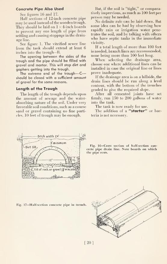
Concrete Pipe Also Used
See figures 16 and 17.
Half sections of 12-inch concrete pipe
may be used instead of the wooden trough.
They should be laid on 1 x 4-inch boards
to prevent any one length of pipe from
settling and causing stoppage in the drain-
age line.
See figure 1. The vitrified sewer line
from the tank should extend at least 6
inches into the trough—B.The opening between the sides of the
trough and the pipe should be filled with
gravel and mortar. This will stop dirt andgophers getting into the trough.
The extreme end of the trough—C
—
should be closed with a sufficient amountof gravel for the same reasons.
Length of the Trough
The length of the trough depends uponthe amount of sewage and the water-
absorbing nature of the soil. Under very
favorable soil conditions, such as a course
sand or gravel containing no fine parti-
cles, 10 feet of trough may be enough.
But, if the soil is "tight," or compara-tively impervious, as much as 100 feet per
person may be needed.
No definite rule can be laid down. But
some idea can be had by observing howrapidly rain or irrigation water pene-
trates the soil, and by talking with others
who have septic tanks in the immediate
vicinity.
If a total length of more than 100 feet
is needed, branch lines are recommended,none being more than 100 feet long.
When selecting the drainage area,
choose one where additional lines can be
installed in case the original line or lines
prove inadequate.
If the drainage area is on a hillside, the
drain lines should be run along a level
contour, with the bottom of the trenches
graded to give the required slope.
After all cemented joints have set
firmly, run 150 to 200 gallons of water
into the tank.
The tank is now ready for use.
The addition of a "starter" or bac-
teria is not necessary.
Fig. 16—Cross section of half-section con-
crete pipe drain line. Note boards on whichthe pipe rests.
Fig. 17—Half-section concrete pipe in trench.
r 20

MAINTENANCE OF THE SEWERAGE SYSTEM
Careful attention to construction de-
tails reduces the possibility of future
trouble in the septic tank sewerage sys-
tem.
Use of Disinfectants
Moderate amounts may be used. Large
amounts of disinfectants or cleaning
agents are detrimental to bacterial activ-
ity in the tank.
Grease Traps
If waste fats and grease are deposited
with the garbage, a grease trap need not
be installed. However, a trap may be de-
sirable if an excessive amount of greasy
water is discharged into the tank.
Grease trap designs are given in U. S.
Dept. Agr. Farmers' Bulletin 1950: 1-30.
1944 under the title "Sewage and GarbageDisposal on the Farm" by J. W. Rockeyand J. W. Simons.
Stoppage
The most common complaint concern-
ing sewerage systems is that waste water
leaves the plumbing fixtures slowly, or
that toilets overflow. This is caused bystoppage in the pipe, tank, or drain line.
Here is the way to locate the stoppage
and to remedy it.
Open drain line near the tank.
If, when the line is opened, water rushes
from the drain line, then the trouble is in
the drainage line.
If the soil around the line is saturated
along the length of line (not because of a
natural high water table) , then the drain
is plugged, or more drain line is needed.
If there is no rush of water when the
line is opened, the stoppage is at the inlet
of the tank or in the sewer line betweenthe house and the tank. To correct this:
1. Remove the second cover slab fromthe inlet end of the tank.
2. Remove the scum from in front of
the inlet baffle.
3. Probe around the inlet.
[
If this does not clear up the stoppage,
then the trouble is in the sewer line.
If this be the case, run heavy wire, a
rod, or a hose with nozzle jetting water,
through the sewer line.
If there are no clean-out plugs in the
sewer line, break a joint to gain entrance.
After the line is cleaned, repair the
broken joint with mortar.
Sometimes Pipe Must Be Relaid
In many disposal systems 4-inch drain
tile has been used for the drainage line.
In time the soil about the joints of the
tile becomes impervious. If this happens
often, the drain pipe should be relaid in
a bed of coarse gravel ; or the open-bottom
drain line described in this circular
should be substituted for the 4-inch tile
line.
Cleaning the Tank
The authors studied the performance
of a number of septic tanks that had been
in use for three to ten years.
The results of this study, which cov-
ered the major portion of California, indi-
cated that sludge accumulated in the
bottom of the No. 1 tank at the rate of
about 1 inch per person per year.
Due to sludge accumulation the ca-
pacity of the tank gradually diminished.
This results in increasing quantities of
sludge being discharged into the drain
line. In time, this causes stoppage in the
drainage system.
On the basis of the study, it is recom-
mended that the No. 1 tank described in
this circular be cleaned in 5 years if 6
persons are in the household, or in 10
years for an average of 3 persons.
How to Clean the Tank
1. Remove the second and third cover
slabs from the inlet end.
2. Remove the scum or mat with a
shovel.
3. Remove the liquid and the sludge.
21]

The liquid and a portion of the sludge
may be removed by a pump if the con-
tents are agitated during pumping.
Allowing water to flow into the tank
aids in pumping.
Bailing the liquid is often the practical
method.
A Good Bailing Pail
A 5-gallon oil can makes a very satis-
factory bailing pail (fig. 18). Strap iron
is bolted or riveted to the edges about the
top and on two sides of the can to rein-
force it. This also provides a suitable sup-
port for the swinging metal handle. Thewooden handle should be at least 6 feet
long.
Disposal
Disposal is simple. Bury the scum, and
run the liquid into a trench that can be
backfilled after a few hours.
'/s"x/\jtr&p /ro/?
j
Fig. 18—Home-made bailing pail.
30m-l,'49(B2020)
22]

Cut Out This Page For Ready Reference
Form for septic tank.
