a review on design, manufacture and mechanics of composite ... · pdf file1 a review on...
TRANSCRIPT
1
A review on design, manufacture and mechanics of composite risers
Pham Dinh Chi*, Sridhar Narayanaswamy
Engineering Mechanics Department, Institute of High Performance Computing
1 Fusionopolis Way, #16-16 Connexis, Singapore 138632
Qian Xudong
Department of Civil and Environmental Engineering, National University of Singapore
1 Engineering Drive 2, E1A 07-03, Singapore 117576
Adam Sobey, Mithila Achintha and Ajit Shenoi
Faculty of Engineering and the Environment, University of Southampton
University Road, Southampton, UK, SO17 1BJ
ABSTRACT
Exploration of deeper oceans for oil and gas requires increasingly lightweight solutions.
A key enabler in this aspect is the use of fiber-reinforced composite materials to replace
metals in risers. However, design synthesis and analyses of composite risers are more
challenging than for conventional metals due to the complex behavior and damage
mechanisms which composite materials exhibit. Composite risers are predicted to be a
high-impact technology that will be mainstream in the medium term but there is still
relatively little literature pertaining directly to the behavior of these materials under the
complex loading scenarios arising from their use in deep water structures. Therefore there
is a need to perform a review and assessment of the available technologies and
methodologies in the literature to gain a good understanding of their predictive
capabilities, efficiency and drawbacks. This article provides a comprehensive review of
published research on manufacture, experimental investigations and numerical analyses
of composite risers in deepwater conditions determining the gaps and key challenges for
the future to increase their application.
Keywords: Composite Riser, Mechanics, Manufacture, oil and gas platforms
*Corresponding author. Tel: +65 64191354; Fax: +65 64674350
Email address: [email protected]
1. Introduction
Fiber reinforced polymer composites are increasingly being used in the marine
and offshore industries. This is especially the case for pipelines/risers, stress joints and
fluid handling since composites offer many important advantages over metals due to their
high specific strength and stiffness, good durability, low thermal conductivity and good
corrosion resistance (Meniconi et al., 2001; Salama et al., 2002; Smith and Leveque,

2
2005; Suresh et al., 2004; Tamarelle and Sparks, 1987). The current trend for the offshore
industry is towards deeper applications; there were 44 fields over 500 m depth in 2000
and 200 in 2007 (Quest Offshore, 2011). The production of oil from deep waters is
expected to increase from 2.5 million barrels per day in 2004 to 8.25 million barrels in
2015 (Lloyd’s Register, 2013).
During this production process the oil must be transported from the well-bore at
the seabed to the connecting rig on the surface and this is generally performed through
tubes called risers. These risers are long and relatively thin, with predicted depths of 4 km
and typical diameters of 100 – 300 mm (Tarnopol'skii et al., 1999). Risers are also used
for drilling which transfer mud to the surface or for production which transport
hydrocarbons, control fluids or gas. Depending on the operating depth range, different
riser configurations are used. Fig. 1 schematically shows different riser/platform
configurations together with a range of operating depths. For some riser applications,
such as the Tension Leg platform, a problem is that the required top tension escalates
considerably with increasing length of the risers.
A number of studies have demonstrated the potential for fiber reinforced polymer
(FRP) composites in deep-water risers at water depths more than 1500 m (Tarnopol'skii
et al., 1999), (Beyle et al., 1997). According to Tarnopol'skii et al. (Tarnopol'skii et al.,
1999), thermoplastic composite risers (TPCR) offer good solutions to current limited
technologies in Top Tensioned Risers (TTRs) and Steel Catenary Risers (SCRs). Both the
metal TTRs and SCRs are generally not able to support their own weights at water depths
higher than 1500 m and the costs for these buoyancy and compensation systems may
further increase with water depth. Ochoa and Salama (Ochoa and Salama, 2005)
acknowledged the potential application of composite risers to extend this capability to a
depth of 3000 m with Tarnopol'skii et al. (Tarnopol'skii et al., 1999) showing a
calculation for steel and composite riser design showing that conventional steel risers
would be 90,000 tonnes compared to a similar composite riser which would be
approximately 20,000 tonnes. Ward et al. (Ward et al., 2007) compared the performance
of steel and CFRP composite production risers operating in the Gulf of Mexico. The
risers have an approximate length of 1800 m, an outer diameter of 0.3 m and a wall
thickness of 0.25 m. The top tension required for the composite riser was reported by
Ward et al. (Ward et al., 2007) 2.7 times less than for the steel using load cases of normal
shut-in with 1-year winter storm and 100-year hurricane. Furthermore, the size of the
tensioner joint and tapered stress joint needed at the top and bottom of the composite riser
system are considerably smaller than the all steel system. Ward et al. (Ward et al., 2007)
also reported risk analyses, in terms of the failure modes and hazard, of the steel and
composite risers. It was shown that composite risers offer better resistance against many
failure modes over steel including burst, collapse, axial yielding of liner, leakage and
crack through the liner and the composite tube. However, there are some issues with
composites in deep water conditions. Tan et al. (Tan et al., 2015) concluded that
composite risers are more vulnerable to vortex-induced-vibrations (VIV) than steel
configurations and therefore fatigue damage for the composite yielded 25.5% higher root
mean square (RMS) strains. It is suggested that some of these effects could be negated by
increasing the fiber-winding angle increasing the load bearing properties and raising
eigenfrequencies, mitigating the VIV. These affects are increased by the degradation of
the material properties due to water. Rege and Lakkad (Rege and Lakkad, 1983) showed
3
the effects of salt water on glass and carbon fibre materials where the results show that
there is a reduction in strength related to the percentage of weight gained, the flexural
strength is more severely degraded than other properties. The strength values decrease is
related to temperature where an increase leads to greater deterioration, which could be
problematic for deeper reservoirs. Siriruk and Penumadu (Siriruk and Penumadu, 2014)
studied the effect of sea condition on cyclic fatigue showing that there was a degradation
in fatigue, compared to testing of dry laminates in air, of 30% for wet laminate tested in
air which compared to 71% for dry laminates immersed in water and 84% for wet
laminates immersed in water. This shows a dramatic reduction in the fatigue life of the
composite. The results obtained for water confined samples with exposed edges, may
overstate the case for marine structures since in many cases only one face will be exposed
to sea water and these results show that dry laminated with one side immersed lost 42%
of their cyclic life and wet one side immersed lost 47%. Kaboudian et al. (Kaboudian et
al., 2014) looked at the distribution of tension along a composite riser showing that this
was relatively constant and that therefore failures will be more scattered than for steel.
They found that the addition of buoys along the riser causes kinks in the tension
distribution and advised that long continuous buoys should be added along the bottom-
half of the riser, instead of shorter buoys with gaps. The longer buoys reduce high
bending strains at the buoy edges and longer modules are also better at reducing the
effects of VIV. Chen et al. (Chen et al., 2013) performed a further study into the effects
of VIV in composite risers and showed that the high stiffness of the liner reduces the
overall performance of the riser as the high strength of the composite can't be fully
utilized. The composite risers require lower top-tension and less or even no buoyancy
leads to a significant reduction in the weight hanging from the platform deck, this is
economically beneficial which increase with increasing length. Tan et al. (Tan et al.,
2015) performed an analysis of coupled fluid-structure simulations against full scale
experiments of 1500 m steel and composite risers. The results show a close correlation
and goes on to compare aluminium, steel and titanium liners showing this is the weakest
link for composite riser design. The titanium liner riser yielded 20% lower RMS strains
than the aluminum liner riser and 10% lower RMS stress than the steel liner riser
concluding that titanium alloys are a better choice than steel due to their density, wear
and corrosion resistance.
Composite risers can be classified into two main types: bonded where there is
binding between the riser’s layers, and un-bonded where riser’s components are able to
move relative to each other, shown in Fig. 2. Bonded risers often include a core fiber-
reinforced angle ply laminate sandwiched between a metallic/elastomeric inner liner and
an outer liner made of thermoplastic or thermoset materials or metal alloys where the
primary role of the liners is to prevent weeping and leakage of the pressurized media as
composite materials are porous (Gibson, 2003). Unbonded flexible risers often comprise
an inner steel carcass layer, to prevent buckling and collapse of the riser; steel pressure
armor layers, to prevent corrosion from inner fluids; anti-wear homogeneous layers;
helically wound tensile armors, to provide axial and bending stiffnesses for the riser, and
an outer polymeric layer for external protection (American Petroleum Institute, 2008).
One of the first examples of composite risers was for a tension leg platform (Sparks,
1986; Sparks et al., 1998). The risers had an external diameter of about 230 mm, a joint
length of 15 m and were made of hybrid ±200 carbon and 90
0 glass composites and can
4
sustain a fatigue life 3 times longer than a steel riser. Other early uses of composites
include the development of production (Baldwin et al., 1998; Baldwin et al., 1997) and
drilling risers (Andersen et al., 1998a; Andersen et al., 1998b) for deepwater. An example
specification of a typical composite riser by Kim (Kim, 2007) is presented in Table 1.
The first application of composite risers in the Norwegian North Sea more than 10
years ago (Salama et al., 2002). Salama et al. (Salama et al., 2002) reported a composite
riser joint installation in the Heidrun tension leg platform (TLP), which experienced
severe loading and operating conditions together with strict regulatory requirements. The
qualification program of the Heirdun TLP composite risers included impact, burst
pressure and bending fatigue tests on full-scale composite specimens. The composite riser
joint was certified by DNV, which participated in the verification and proof testing of the
field joint prior to the installation. The offshore field demonstration established a feasible
installation process together with an in-service inspection strategy. Despite the high cost
of composite risers and riser joints, Salama et al. (Salama et al., 2002) confirmed that
composite risers impact the life cycle economics by improving payload capacity,
increasing water depth capability, improving overall system safety and reliability, and
reducing maintenance costs. In a more recent effort, Miyazaki et al. (Miyazaki et al.)
reported the development of a 4000 m CFRP drilling riser for deep sea drilling vessels.
Their research confirmed, via testing of small-scale riser models, the performance of the
CFRP risers in the deep-water environment. However, the full implementation of the
composite riser requires further enhancement of the connection between the steel flange
and the composite pipe, as well as validations of its performance under fatigue and torque
loadings. A number of companies have already invested in the development of composite
risers around the world, including Conoco, Petrabras, Shell and Statoil. (Gibson, 2003).
Composites demonstrate great potential for deep-sea operations. A recent
assessment of industry trends and drivers (Bowden et al., 2014) lists composite risers as a
high-impact technology that will be mainstream in the medium term, 2020. However,
composites have not been used to their full potential within riser applications. There are
examples such as the large safety factors, in the order of 15-50, were recommended by
some design standards such as DNV-RP-F202 (Det Norske Veritas, 2009), reflecting the
lack of reliable life prediction and lack of rationale and standardization in experiments
and modelling. Thus there is a need to advance the understanding on the subject and
reduce error and uncertainty margins underpinning safety factors. There has been no
recent review of the literature to consolidate this knowledge despite earlier attempts to
consolidate an understanding of the behaviour and problems related to composite riser
design (Ochoa and Salama, 2005). Therefore the current paper reviews existing work in
designing, testing and modelling composite materials at the component and structural
levels, summarizes the current state of the art research and identifies key challenges for
the future.
2. Design loads for composite riser
Summerscales (Summerscales, 2014) described riser environments as “being for
long periods of time, often greater than 20 years, with a minimal amount of maintenance
under high hydrostatic loads and high thermal gradients”. Guesnon et al. (Guesnon et al.,
5
2002) expanded on these difficulties for ultra-deep water drilling to include water depth,
mud weight, auxiliary line diameters and working pressures, sea states and current
profiles and maximum rig offset.
The loading scenario is complex as different loads are created by the currents and
surface waves, the pressures due to the change in depth and the interaction of the risers
with other systems or risers. DNV-OS-F201 (Det Norske Veritas, 2010b) classifies the
loads acting on risers under deepwater environments as pressure loads, functional loads,
environmental loads and accidental loads, examples of which are given in Table 2. More
specifically the design criteria for risers should consider hydrostatic collapse due to
buckling load, mechanical collapse under tension, compression, torsion, ovalization, the
squashing of the circular risers into an oval shape, and service life factors given in DNV-
OSS-302 (Det Norske Veritas, 2010a). Each of these loads must be treated differently
and there are a number of methods to model each. This review focuses on riser structures
and materials aspects but a summary of the environment and loads are included as an
integral background to these models.
Risers are subject to pressure loads such as external hydrostatic pressure, internal
fluid pressure, both static and dynamic, and the pressure caused by the depth at which the
risers operate.
The functional loads include the applied top-tension of risers during the
installation or construction, thermal loads due to thermal differences between the sea
water and riser structure, or the weight of internal fluid, riser, casings, coatings or
buoyancy modules.
Environmental loads are mostly due to the different currents and surface waves.
As an example for a riser, Larsen (Larsen, 1992) predicts the currents to be in the region
of 1 m/s with a wave height of 15 m and a wave period of 12 s. Some estimated values
for the loads and utilization factors of a riser with an internal diameter of 150 mm at high
depth of ~3000 m are given by Hill et al. (Hill et al., 2006) and reproduced in Table 3.
For more details, Patel and Seyed (Patel and Seyed, 1995) provide a review on the
modeling and analysis techniques available to make a hydrodynamic assessment of
flexible risers giving a good basis for static and dynamic analysis, internal and external
pressure effects and includes information on fluid flows.
For many applications, calculations of the hydrodynamic loads typically use
Morrison’s equation, outlined in (Morison et al., 1950) and (Guesnon et al., 2002). This
approach incorporates the drag force due to the relative fluid velocity, the inertia force
due to the structural acceleration and the inertia force due to the wave acceleration, albeit
that the viscous effects are not accounted for. The fluid velocity and acceleration are
specified to estimate fluid drag and inertia loads and the pressure field fluctuation is used
to calculate the buoyancy load. However, these equations cannot account for some of the
more complex fluid phenomena such as vortex induced vibrations. As the fluid flows
pass the body, they can separate creating a pattern of vortices changing the pressure
distribution along the body surface. These periodical irregularities of the flow can create
vortex induced vibrations with motions in the region of 0.6 diameters (He and Low,
2012). These flows are difficult to predict and when the riser is flexible these can result in
complex fluid-structure interactions. The longer and more slender the structure is, the
more important such interactions become. The vortex-induced vibrations (VIV) are
predominant in fatigue of riser structures as investigated by Gao et al. (Gao et al., 2011)

6
and the American Bureau of Shipping (ABS) design guide (ABS, 2006) recommends
explicit VIV fatigue analysis to mitigate vibration. He and Low (He and Low, 2012)
highlighted the importance of vortex-induced vibrations and wake-induced oscillations
for predicting the behavior of multiple risers due to clashing. This is an area of much
current interest with improvements to the methodologies being presented by many
authors including Modarres-Sadeghi et al. (Modarres-Sadeghi et al., 2011) and Dahl et al.
(Dahl et al., 2007).
Different from the afore-mentioned loads, accidental loads, such as dropped
objects, trawl board impacts or unintended flooding, are defined by a risk analysis and
should be assessed with regards to a target failure probability. This ensures that the
annual probability of these accidents occurring is less often than a predetermined value,
usually in the region of 10-3
to 10-5
. This is done by estimation of the load effects on the
riser design and structure to ensure that the overall failure probability is less than the
target failure probability. Standard practices such as DNV-OS-F201 (Det Norske Veritas,
2010b) assume an annual failure probability of 10-4
for accidental loads on risers with a
safety factor of 1.
Overall, risers are subjected to variable and uncertain loads owing to the harsh
environment in which they function. Large wave and current loads can be exacerbated by
vortex-induced vibrations and wave-induced oscillations significantly contributing to
damage and failure of risers. Structural calculation methods must be capable of dealing
with these loading scenarios, and more importantly, the complex interactions that result.
Many current analysis methods use simplified loading scenarios to estimate these loads
and more complex scenarios must be investigated to see the long terms effects of these
additional loads.
3. Manufacture
Fiber reinforced polymer composite risers have higher initial material and
manufacturing costs than conventional metals but the maintenance costs are lower
(Fowler et al., 1998) and there are predictions of a 37% reduction in overall installation
costs (Ochoa and Salama, 2005).
Design and manufacture of composite risers can be mainly considered at the
composite riser body, the metal end fittings where multiple risers are joined together and
the metal-to-composite interface (MCI). DNV-OSS-302 (Det Norske Veritas, 2010a)
provides detailed design criteria for bonded FRP risers in terms of design parameters. The
key parameters for bonded risers are the strains of the elastomer layers and the stresses of
the reinforcement layers, the liners and the connection mechanisms by the MCI design.
The manufacture section of risers can therefore be discussed through two main aspects:
the riser body and the MCI and end fittings.
3.1 Composite riser body
Composite risers are often manufactured with short segments, called riser joints,
fabricated first which are connected together to form a long riser. Composite riser joints
are manufactured with a laminated pipe body and metal end fittings with circumferential
7
grooves at riser terminations. Pultrusion and filament winding methods are the two main
methods to produce FRP composite tubes with constant and tubular cross-sections. The
pultrusion method is capable of producing long FRP tubes with small diameters but may
not be preferred for fabrication of risers as relatively large diameters are often employed.
On the other hand, filament winding is able to make large diameter composite tube
though it is restricted to a few-meter length due to the limitation of the mandrel length.
This requires that many sections must be joined together to create a suitable length by
filament winding. Furthermore, this process is labour intensive increasing the cost and
reducing the take up of the material. Nevertheless, wet filament winding is the most
popular technique for manufacturing of composite risers (Ochoa, 2006; Pierce, 1987;
Salama and Spencer, 2010; Thomas, 2004).
Cocks (Cocks, 1982) patented a method for manufacture of a steel reinforced pipe
based on the filament winding. The pipe includes: an inner liner made of wound layers of
resin-impregnated glass fibers, a middle structural section made of at least three layers of
steel strips of 0.25 mm – 0.75 mm thickness and 100 mm – 200 mm width which are
helically wound about the longitudinal axis of the pipe, axially spaced about 3 mm and
radially spaced smaller than 0.25 mm from one another; and an outer liner of successive
woven glass fiber layers. Such a steel reinforced pipe structure can achieve much higher
strength to weight ratio than traditional steel pipes and provide a weight saving of 50
percent of a steel pipe with the same size.
Williams (Williams, 1994) later discovered a composite laminated tubing for
marine production risers which is suitable for high temperature change under the sea
environment. The pipe comprises multiple FRP composite layers with at least one layer
oriented in the longitudinal direction of the pipe and has a low thermal coefficient of
expansion and a Poisson ratio from 0.4 – 0.6. Such a pipe is highly desirable for use in
the environment where small change in pipe’s length due to high temperature and
pressure variation is expected.
The steps for manufacturing a composite production riser by filament winding
were given by Thomas (Thomas, 2004). The first manufacturing step is often to machine
the trap-lock MCI which consists of multiple grooves to trap a series of composite layers
(Ochoa, 2006; Salama and Spencer, 2010; Thomas, 2004) and installing them on a
mandrel. An elastomer layer such as the uncured hydrogen resistant rubber (HNBR) is
then wrapped on the mandrel and the MCI to produce an inner liner of the riser. Next,
helically wound glass/carbon fibers impregnated with epoxy resin are placed over the
HNBR and secured by the trap locking mechanisms of the MCI. Additional
circumferential impregnated-fiber layers can be wound to the assembly to provide hoop
strengths for the pipe. Subsequently, the mandrel is removed from the assembly and heat
is applied to compact all of the layers. After the curing, another layer of HNBR and
impregnated fiber may be added and heated again to provide external protection of the
assembly against abrasion and external pressure. In this application, the use of HNBR
layers allows small relative motions between the metal liner and composite layers; thus
helping accommodate for differences in CTE of these layers helping to reduce stress
induced microcracks. Recent research efforts (Ramirez and Engelhardt, 2009) have
confirmed the performance of the large-scale composite riser tubes under high external
pressures. The world’s first composite riser installed for the Heidrun platform has used
the filament wound technology in the fabrication of the risers (Spencer, 2002). Spencer

8
(Spencer, 2002) summarized the manufacturing process, testing and field use of this
composite riser project.
For future developments in composite riser manufacture, Salama et al. (Salama
and Spencer, 2010) recently invented a method of manufacturing a composite riser
section and MCI through filament winding and a horizontal liner assembly, as depicted in
Fig. 3. The proposed liner assembly is held in a horizontal position by two supports
without inserting a mandrel and rotated about its longitudinal axis by a number of rollers.
As described by Salama and Spencer (Salama and Spencer, 2010), composite risers can
be constructed with a thin tubular titanium or steel liner which is secured to a connector
assembly. Both the metal liner and connector assembly are covered by an elastomer shear
ply. A number of helical windings of composite fibers are then placed to form a
composite riser section in which at least one winding layer of resin impregnated fibers is
oriented at an angle perpendicular to the longitudinal axis of the liner assembly. This
composite section is heated to cure the shear ply and composite plies. After this step,
external elastomer jackets can be applied and additional composite layers can be wound
to secure the jacket and supply external resistance to the composite section. It was
claimed that the composite section manufactured with the aforementioned liner assembly
will offer excellent strength weight characteristics and durability in comparison with steel
risers. Bailey and Miller (Bailey and Miller, 2011) have developed a method to
manufacture very long large diameter pipes. This method utilizes a number of pultruded
segments which are joined side-by-side rather than end-to-end. Each pultruded segment
therefore has a length equal to the length of the desired pipe with as many sections as
required for the diameter of the pipe. This reduces the number of joints, and the
associated cost while making it easy to transport. Anderson and Altan (Anderson and
Altan, 2012) have proposed a method for bladder assisted composite manufacture. This
method was reported to be a cost effective method for production of medium to large
structural composite components and can be considered as a viable alternative to filament
winding, pultrusion, or autoclave curing. The process is similar to flexible bladder
molding but the heating source is moved inside the uncured layup. This leads to accurate
control of the temperature but also reduces energy requirements by 50% for cylinders
than the traditional bladder approach. Another potential method for composite riser
manufacture is pull-winding, a process which is a combination of filament winding and
pultrusion. Filament winding is the cheapest method and the easiest to manufacture but
can lead to asymmetric layups. Pull braiding is the most expensive process and also the
most difficult from manufacturer point of view. Pull-winding is between these two
processes providing a compromise between quality and cost (Guz et al., 2015).In the pull
winding process, the 0° oriented material is either fed into the process as a prefabricated
rod or fed into the assembly as a pre-preg tape or wet layout. Cross-ply material is then
wound onto the tube and the assembly is pulled through a die for integral curing. The
pultrusion process may utilize material which is prepared by weaving or braiding the
fibers. Woven or braided material can be prepared as feed stock or can be fabricated on-
line as a part of the pultrusion operation (Williams and Sas-Jaworsky, 1999). There were
also a number of manufacture methods for spoolable pipes at Deepflex documented in a
number of patents: Kalman et al. (Kalman et al., 2013), Chen (Chen, 2014), and Bryant
(Bryant, 2006) covering a manufacturing method for an armour layer of a spoolable pipe,
a method for flexible pipe structures with a T-shaped cross section and a method of
9
securing the inner polymeric core to the first layer of reinforcement for internal fluid
pressure resistance. These methods help provide spoolable pipe with increased collapse
resistance and enhanced compressive strength.
3.2 Metal to composite interface and end fitting
The MCI is mainly used to provide a strong interface/connection between the
composite pipe body and the metallic end fittings at pipe’s terminations thus may help
effectively transfer loads between the pipes. Efficient designs of the MCI are important
since their length and mass may significantly affect the weight-effective use of composite
risers and failure often occurs at this point during operation.
Roberts and Hatton (Roberts and Hatton, 2013) addressed the importance and
design challenges of metallic end fittings at termination of composite pipes. Efficient
designs of end fitting are essential to ensure good load transferring between composite
and metallic materials as well as to avoid potential failures at the interfaces. Roberts and
Hatton (Roberts and Hatton, 2013) presented various arrangement designs for the end
fitting of composite risers, as shown in Fig. 4, including the trap-lock end fitting, swaged
end fitting, metallic liner end fitting and Magma end fitting. The trap lock end fitting
(Fig. 4a) has been the most popular design allowing load transfer between composite and
metal components. Another design is the swaged end fitting, shown in Fig. 4b, where
metallic inner and outer sleeves are used to sandwich the composite pipe. The inner
sleeve fits with the composite bore whilst the outer sleeve is swaged to get an
interference fit with the composite pipe. Load transfer is achieved through friction and
mechanical interferences. However, there are possibly high stress concentrations and
potential damage at the interfaces between the outer sleeve and composite material and at
the region where the inner mandrel is inserted. Thus, this design may be suitable only for
composite pipes with small diameters. Another design is the metal liner end fitting shown
in Fig 4c which is often used in hybrid composite tubes (Cederberg, 2011; Guesnon and
Schaeffner, 2002). By this design, the metal liner is directly welded with the end fitting
and composite materials are wound over the metal liner. A rubber layer also needs to be
applied before winding the composite materials. This design enables the axial load to be
handled separately by the metal liner whereas the hoop load is carried by the composite
material. It is observed that a long metal liner is required for this configuration reducing
the weight saved by using the composite pipes. Recently, Magma has developed another
end fitting design, shown in Fig. 4d for a new monolithic structure from bore to surface
riser, with high strength carbon fiber and PEEK thermoplastic polymer (Damon, 2011;
Magma, 2012; Stephen, 2011). As highlighted by Roberts and Hatton (Roberts and
Hatton, 2013), this design allows the thickness at the pipe end to be built up and it is
possible to replace of the end fitting, increasing the strength to that of the pipe. Two
thickening stages for the composite pipe are suggested to increase the local strength of
the pipe at the interface between the pipe and steel outer collar. Sealing between the
composite pipe and metal fitting is provided by the use of a preloaded bore seal which
can be made of stainless steel or PEEK. It is found that the Magma end fitting design is
able to provide good structural interface and increase fatigue performance for both the
end fitting and the composite pipe (Roberts and Hatton, 2013).
10
While there is a large body of research covering analyses of composite tube under
different load applications, studies on the MCI still remain limited. Cederberg
(Cederberg, 2011) presented both experimental and numerical analyses of a composite
riser joint including the MCI for a pre-stressing step by autofrettage and a factory
acceptance test (FAT). Composite and steel components were modelled using a general
purpose FE code and their interaction was defined by a surface contact. The FE model of
the riser joint is shown in Fig. 5. Tension and pressures following the autofrettage and
FAT were applied through five steps: 1) pulling the steel pipe in the axial direction; 2)
applying internal pressure at a level greater than its yielding strength; 3) removing the
internal pressure; 4) re-applying the pressure at a lower level and 5) releasing the
pressure. The stress (ksi) – strain responses of both the steel pipe (X80) and CFRP tube
for each step are plotted in Fig. 6. The material responses during the autofrettage and
FAT show a high hoop stress and relatively lower axial stress predicted for the composite
layers. At the end of the autofrettage step, an interference fit between the steel and
composite components is obtained, leaving the composite tube in tension and the pipe in
compression. Compressive hoop stress of the steel pipe is shown in Fig. 7. For the
composite tube, high fiber stress in each layer is predicted within the constant cross-
section region of the composite body and the stress decreases towards the MCI end (Fig.
8).
3.3 Summary
Disadvantages on manufacturing techniques such as filament winding or
pultrusion form an inhibitor to composite riser construction while keeping the initial
production costs relatively high. More difficulties are imposed when there is a lack of
infrastructure for mass production of large-diameter and long tubular pipes required for
deepwater risers. Filament winding has so far been shown to be one of the most popular
fabrication methods for the composite material. Whilst this process has been proven to be
beneficial for short-length risers in the future, as manufacture moves towards increased
lengths, this might not be the case. This technique will need to be combined with drawing
of the tubular shape such as in the pultrusion process though current pultrusion
techniques are incapable of the diameters required for offshore applications. A number of
new manufacturing processes have emerged such as additive manufacturing providing
added benefits in producing long pipes over the current filament winding processes.
However, for their introduction surpassing the technical barriers will not be enough.
There must be a culture shift to embrace new technologies which will need to be
balanced with proof that new techniques ensure a reliable and economic alternative. At
the ends of the riser, end fittings with sealing mechanisms are needed to connect different
pipe segments to form a long riser. The elastomer liners that are used can easily fail and
are therefore not preferred for production and drilling risers. Various types of end fitting
designs are discussed in Roberts and Hatton (Roberts and Hatton, 2013) allowing more
flexible choices of pipe designs and MCI configurations for the connection between the
composite body and metal end fitting. Efficient designs for end fitting are crucial for
minimizing the damages at the composite/metal interfaces as well as guarantee good load
transferring between the composite pipe and metal components. Apart from these end
fitting design, an effective choice of composite material candidates such as the high

11
performance Carbon PEEK composite (Damon, 2011; Magma, 2012; Roberts and
Hatton, 2013; Stephen, 2011) is also seen to improve the performance of the pipe.
4. Experimental testing on composite risers
Over the past decades, numerous experimental programs have been performed to
examine the mechanical performance of composite risers under static and fatigue tests to
ensure their applicability in the deep-water environment. The testing programs can be
grouped into those performed at the material, small-scale structural and full-scale riser
levels. While most of the tests are done at the coupon level and some can be found on the
small-length risers, existing studies on the large scale risers are still limited.
4.1 Small-scale material and structural testing
Ochoa and Ross (Ochoa and Ross, 1998) and Grant and Bradley (Grant and
Bradley, 1995) examined the degradation of glass-epoxy and graphite-epoxy composite
tubes due to different seawater levels and obtained a good correlation between the
analysis and experimental data for flexural response of the composite tubes. Rodriguez
and Ochoa (Rodriguez and Ochoa, 2004) reported a four-point bending test comparison
between carbon-fiber and glass-fiber epoxy tubes. The composite tube specimens
reported have a fixed diameter of 54.8 mm with a thickness from 2.6 mm to 3.3 mm. The
dominant failure mechanism observed during the test was sub-laminate buckling
followed by fracture, located in the axially compressive dies of the composite tube.
Other experimental studies have focused on enhancing the toughness and ductility
of the composite riser materials. Sobrinho et al. (Sobrinho et al., 2010; Sobrinho et al.,
2011) reported an experimental effort to enhance the toughness of the composite risers by
introducing a toughening agent, rubber, into the epoxy resin which increases the
elongation of the composite material but results in a compromised tensile strength and a
reduced elastic modulus. For riser components and their connections, DNV-RP-F202
(Det Norske Veritas, 2009) suggests test requirements of the MCI on the design phase
and after fabrication including axial, bending fatigue tests, stress rupture and external
pressure tests of both the MCI and end fittings.
For fatigue, studies on composite tubes include (Soden et al., 1993), (Ellyin et al.,
1997), (Ellyin and Martens, 2001), (Mertiny et al., 2004) where the fatigue responses of
FRP composite tubes under uniaxial and bi-axial loadings and the effects of fiber
orientations on the structural responses were analyzed. Soden et al. (Soden et al., 1993)
highlighted the necessity for fatigue testing using tri-axial loads. Ellyin et al. (Ellyin et
al., 1997) developed stress-strain curves and biaxial failure envelopes for filament wound
specimens. An extension of the study was done by Ellyin and Martens (Ellyin and
Martens, 2001) where it is shown that optimum fiber placement in principal directions
sometimes lead to weak behavior for intermediate loads and imperfections in the
manufacturing process can contribute to damage initiation at the early stage and shorten
the fatigue lives of composites. Mertiny et al. (Mertiny et al., 2004) revealed the benefits
of the multi-angle winding technology providing more resistance to damage.
With efforts to develop testing methods for full-length composite tubes,
Chouchaoui (Chouchaoui and Ochoa, 1999; Chouchaoui et al., 1999) and Rodriguez and

12
Ochoa (Rodriguez and Ochoa, 2004) addressed the scaling effects of composite tubes
under different loading cases taking into account various geometries, material properties
and fiber orientations. However, the developed scaling methods may be applicable to
small-scale tubes but have not been fully verified for large-scale specimens.
4.2 Full-scale riser testing
Salama et al. (Salama et al., 1998) reported a research program to develop testing
and qualification procedures to validate the design and long-term performance of
composite production risers for a tension leg platform in the Gulf of Mexico. The testing
program developed in their research efforts aims at identifying the performance
limitations, failure envelopes and the manufacturing requirements for the composite
production risers.
Sparks et al. (Sparks et al., 1998) reported the first mechanical testing of six high-
performance composite tubes to be used as production risers for tension-leg-platforms to
be used at water depths of 500 to 1000 m showing that there was an economic benefit in
using composite materials for tension-leg-platforms. Salama et al. (Salama et al., 2002)
performed mechanical and fatigue tests on full-scale, 15 m length and 550 mm diameter,
samples demonstrating that composite risers can be designed to satisfy all operational,
environmental, and regulatory requirements. Gibson (Gibson, 2003) summarized research
on the cost-effective use of FRPs for offshore applications over a 13-year period from
1988 to 2001. This extensive research effort covers a wide spectrum of uses for
composite materials in the offshore environment including fire, blast and impact loading
and durability.
Recent programs on large scale composite testing have been performed by
Ramirez and Engelhardt (Ramirez and Engelhardt, 2009) in which a collapse pressure
test was performed on full-scale carbon fiber-epoxy filament-wound tubes of 4.57 m
long, 564 mm wide and 30.5 mm thick to determine the capacity of the composite pipes
against internal pressure. The study indicates that the delamination in the wall of the
composite pipe can cause a significant decrease in the pressure resistance. Other
programs on large scale design and manufacturing are reported by Thomas (Thomas,
2004) where drilling and production risers were both assessed statically and for fatigue.
75 short full-scale specimens and 9 MCI joints were tested to empirically characterize
strength and fatigue. The program also demonstrated that composite materials would lead
to a cost reduction with minimal improvements to the manufacturing process.
4.3 Summary
A review of the literature is given in Table 4 which shows that there has been
some initial experimental development in investigating the design and mechanical
performance of composite risers in deepwater applications. Much of the current analysis
has been drawn from experiments on generic composite materials and cylinders. Whilst
this allows the general behavior of the materials to be analyzed, specific properties and
behavior are still rare. Experimental work mainly focuses on the mechanical behavior of
small-scale composite tubes subjected to tension, bending, and burst pressure under
different environmental conditions. These developments lead to the subsequent

13
development of guidelines on the qualification tests for composite risers in the design
codes. However, full-scale tests for the composite pipes are still limited and the
significance of scaling effects of risers from small scale to large scale have not been fully
addressed in the literature which can reduce the associated manufacture and testing costs
required for full-length risers. There is considerably less documented research related to
axisymmetric loadings, such as torsion, or related to accidental type loadings, such as
burst. This is compounded by the lack of available data related to in-situ behavior of
current riser applications making the determination of behavior of composite risers
difficult. Through this testing there is little consensus reached on the methods for testing
different mechanical or thermo-mechanical conditions that replicate real riser conditions.
This will be required to develop accurate testing for components of risers and is a barrier
in enabling wider application of composites.
5. Mechanical behavior modeling
Current numerical analyses and modeling methods of composite risers originate
from the studies on local mechanical behavior of composite tubes under static and fatigue
loading and further developed to composite risers considering riser’s components and
deep water environmental effects. The review on analysis method can be categorized into
three main groups covering combined loading, replication of realistic environments and
fatigue.
5.1 Mechanical behavior modeling of composites under combined loading
There are various studies in literature covering mechanics and nonlinear failure
analyses of composite cylinders under complicated load applications which are similar to
the conditions that composite risers may undergo under deepwater condition. Most of the
studies focus on realistic replication of buckling of composite cylinders under bending
and combined loads. Corona and Rodrigues (Corona and Rodrigues, 1995) carried out a
study on the bending response of long and thin-walled cross-ply composite cylinders
including three phases: pre-buckling response, material failure by Tsai-Wu criterion, and
shell-type bifurcation buckling. The bending moment-curvature behavior of the linear
elastic composite tube was observed to be nonlinear due to the progressive ovalization of
the cross-section, which correlates well with the reports by Brazier (Brazier, 1927) and
Reissner and Weinitschke (Reissner and Weinitschke, 1962). Buckling failure can also
be considered to occur when maximum compressive stress in the structure reaches the
critical stress under pure compression (Seide and Weingarten, 1961) or when the pre-
buckling load significantly contributes to the bifurcation load through ovalization
(Axelrad, 1965, 1987). Higher maximum bucking load of the cylinder is to be attained if
the fibers in the inner and outer layers are oriented circumferentially in an analysis
without consideration of the nonlinear pre-buckling behavior (Cheng and Ugural, 1968).
For buckling-induced delamination, Theotokoglou (Theotokoglou, 2006)
investigated the response of Carbon/PEEK composite tubes with an internal diameter of
177 mm and thickness of 16 mm for deepwater applications subjected to external
pressure. Although cylinder tubes can fail in multiple ways under combined axial-
14
pressure loadings (Marinucci and de Andrade, 2006; Tafreshi, 2004; Wiggenraad et al.,
1996), delamination-type failure was commonly encountered in thick composite cylinders
(Bai et al., 1997; Rasheed and Tassoulas, 2001; Zhao et al., 2000). Potential delamination
of the cylinder can be annular delamination (Kachanov, 1988), strip-type delamination
(Timoshenko and Gere, 1961) and buckling of the delamination regions. In
(Theotokoglou, 2006), failed elements were removed to reflect the loss of load-carrying
capability of the cylinder due to three mode cases: external pressure, thermal loading and
buckling load. It is suggested that the delaminated areas may not grow under the design
external pressure if no buckling occurs. When buckling is identified, a portion of the
delaminated regions cannot carry load and the cylinder will fail at a pressure below the
critical design pressure. However, only 2D finite element models were used and 3D finite
element models are recommended to verify the results and the effects of length and depth
of delamination on the calculation of buckling loads.
5.2 Mechanical behavior modeling of composite risers under deepwater
environment
Based on numerical methods developed for composite materials, extensions and
application of the analysis methods for FRP composite risers requires full consideration
of the riser’s components, the connection mechanisms and the fluid structure interaction
between the structural domain of risers and the sea water domain.
To address the plasticity of liners in composite pipes, Vedvik and Gustafson
(Vedvik and Gustafson, 2008) analyzed filament wound thick shells with metal liners
subjected to progressive matrix cracking and plastic flow under axial loading. The
developed damage models based on the minimum potential energy approach were able to
simultaneously predict the progressive transverse cracking of [±550] and [±45
0] laminates
and plastic yielding of the metal liner. Mendelson (Mendelson, 1968) employed the
successive elastic solution with von Mises yield criterion for plastically modeling the
liner. It was found that when both methods were applied in parallel, the equilibrium
conditions and two convergence criteria must be fulfilled for every load increment.
Andersen (Andersen, 1996) further coupled minimum potential energy approach based
on the displacement field with the average maximum stress, average maximum strain,
maximum point stress and maximum point strain criteria to effectively model progressive
damage.
Recently, Sun et al. (Sun et al., 2013) proposed a homogenization approach for
stress analysis of multilayer production risers where composite risers were considered as
one homogenized orthotropic layer with blended elastic properties. Stress analyses were
performed under typical loading conditions of axial tension, pressure loads, bending and
torsion. The stress/strain distribution of the homogenized model follows the orthotropic
method presented by Lekhnitskii (Lekhnitskii, 1981), with each layer calculated from
those of the homogenized layer through the coefficient matrices. The predicted
stress/strain distribution agrees favorably with solutions developed by Xia et al. (Xia et
al., 2001) or Tarn and Wang (Tarn and Wang, 2001) who uses a state space
approach indicating that extension, torsion and pressuring interact. These deformations
are uncoupled with bending of the tube. This method may be accurate for balanced angle-
ply composite laminates but the accuracy must be investigated for composite cylinders

15
with unbalanced angle plies. It is also noted that a number of methods can be used for
determination of homogenized constants such as those based on constant stress/strain
assumption for flat composites by Sun and Li (Sun and Sijian Li, 1988) and Enie and
Rizzo (Enie and Rizzo, 1970) or self-consistent mechanics methods for general
composites with micro-cracks by Huang et al. (Huang et al., 1993) and Huang and Hu
(Huang and Hu, 1994).
Additional efforts to account for environmental effects in the global analysis of
riser’s behavior include Meniconi et al. (Meniconi et al., 2001) who used hydrodynamic
finite element methods to estimate the axial forces and bending moments of the hybrid
carbon and glass epoxy composite risers for a tension leg platform considering different
environmental loads. Progressive failure analyses of composite taper joints were also
carried out and stresses at various sections of the joint were evaluated based on the thick
cylinder theory. The maximum stress criterion and progressive failure approach proposed
in Hinton et al. (Hinton et al., 1996) was adopted for delamination analysis of the taper
joints, an initial crack was assumed and a virtual crack closure technique was applied.
The results show that composite risers which satisfy design and strength requirements can
weigh half as much as an equivalent steel riser. In addition, Pina et al. (Pina et al., 2011)
and Vieira et al. (Vieira et al., 2008) utilized an analytical catenary solver to perform a
global analysis of bonded composite risers. Abouhamze and Shakeri (Abouhamze and
Shakeri, 2007), Larson and Hanson (Larsen and Hanson, 1999) and Lima et al. (Leite
Pires de Lima et al., 2005) carried out static finite analyses to estimate the axial force of
the risers and account for the inextensibility conditions of the riser under distributed
vertical load. Ramos and Pesce (Ramos and Pesce, 2004) presented an analytical model
to predict the behavior of flexible risers under complex combination of loads including
bending, twisting, tension with the presence of internal and external pressure. The
successful modeling of stick-slip behaviors between the riser layers allows a coupling
between bending and axisymmetric loads. Whilst advocating the benefits of optimization
techniques for composite risers, due to their complexity, Silva et al. (Silva et al., 2013)
showed a global-local method which was used instead of shell models, which have a
prohibitively high computational cost for full riser structures. The model was based on a
simplified catenary solver for the global model and classical laminate plate theory for the
local model. Though it is proposed as a robust implementation environmental loads and
fatigue were ignored making it unsuitable for detailed studies. Recently, Pham et al.
(Pham et al., 2014) and Edmans et al. (Edmans et al., 2014) have described a sequential
local-global approach for multiscale modeling of unbonded flexible risers subjected to
combined loadings. RVE analyses of flexible pipes were first performed to derive non-
linear constitutive model for flexible risers based on homogenization theory and the
analogy between slipping mechanisms observed in flexible pipe and the elasto-plastic
behavior of materials. Global analysis or risers were then performed using hybrid beam
elements and the developed constitutive model to effectively predict the response of the
risers under axial loading, bending, torsion and internal and external pressures. Sun et al.
(Sun et al., 2014) propose another homogenization method for anisotropic composite
cylindrical structures comparing the results to two different FEA methods, one based on
multiple solid elements through the thickness and the second where the liner, the outer
layer, the 20 composite layers are modeled with one through-thickness element each. The
results demonstrate excellent correlation across a number of different loading conditions,
16
axial force, internal and external pressure, axial and in-plane shear, bending moments and
torsion whilst also showing that both FEM methods provide similar results. The examples
showed that the material anisotropy may have significant effects on the effective axial,
torsional and coupling stiffness coefficients of composite cylindrical structures but
insignificant effects on the effective bending stiffness coefficient.
A key part of the riser analysis is the linkage between the global and local models.
Chen et al. (Chen et al., 2013) use the critical moments, pressures and tensions obtained
from a global analysis to check the local structural strength which provides a simple and
effective method of linking the global and local analysis. A similar method is utilized by
Silva et al. (Silva et al., 2013) using load and amplification factors to account for
pressure, bending moments and environmental loads through the tension forces of
classical laminate plate theory. Pham et al. (Pham et al., 2015) described a nested
multiscale method for flexible risers to concurrently link the global analysis of the
flexible pipe and the RVE analysis of the local regions of interests in every load step. A
linking procedure between the scales has been implemented through Python scripting and
restart analyses.
5.3 Fatigue analysis
Fatigue of composites may start from the microscopic scale which involves
microscopic failure in constituent fiber, matrix or fiber/matrix interface to the
macroscopic scale that considers failure at structural level. Fatigue of composites
significantly differs from metals since stiffness degradation can be observed early during
the initial stages of fatigue and may potentially lead to major stiffness reduction during
the fatigue process.
Determination of the fatigue behavior of composites at the material level is driven
primarily by other industries and specific investigations into the fatigue performance of a
FRP riser product remains scant. As highlighted by Ochoa and Salama (Ochoa and
Salama, 2005), the lack of experimental database for long-term damage mechanisms
required by the accurate fatigue life prediction remains as one of the basic technical
barriers for wide industrial applications of composite risers. A reliable S-N curve has not
yet evolved for composite risers. The lack of experimental efforts on the composite risers
leads to a large factor of safety (15 to 50) in the offshore design recommendations (Det
Norske Veritas, 2009). The fatigue failure of a composite riser product is evidently a
complex process, involving multiple failure mechanisms. Huybrechts (Huybrechts, 2002)
highlighted that the design of the CFRP composite riser should ensure that the fatigue
failure is determined predominantly by the fiber-failure to ensure a long lifetime of the
riser. The fatigue design procedure outlined in the design guideline thus follows primarily
the approach developed for wind turbine blades (Echtermeyer et al., 1996), of which the
fatigue failure mechanism remains mainly the fiber failure. The high uncertainties in the
DNV guidelines, as reflected by the large factors of safety, derive essentially from the
Miner’s rule, which does not provide a satisfactory description of the fatigue performance
of composite materials, as demonstrated by experimental investigations (Broutman and
Sahu, 1972). The development of a comprehensive fatigue design procedure requires
extensive experimental data for composite riser prototypes fabricated following the exact
procedure as that for commercial products. Some research, led by industrial companies
17
(Cederberg, 2011; Huybrechts, 2002), have started fatigue tests on composite riser
specimens. However, no detailed results are available in public literature.
5.4 Summary
Overall, research on composite pipes over the last few decades has covered the
buckling responses and possible delamination-type failures in composites due to bending,
compression or combined axial-bending loadings which can be representative of
complicated loading conditions that composite risers are subject to. Table 5 highlights
numerical methods for composite risers and it is possible to see that the modelling is
often performed at a simple and analytical level. As highlighted the environmental
conditions for risers lead to a complex interaction of loads but there are limited
investigations into composite risers under realistic deepwater conditions fully considering
the interaction effects between different mechanical and environmental loads. Further
developments on effective numerical models of composite risers subject to mimicked
deepwater environment are crucial. It is suggested that efficient multiscale approaches
with consistent scale bridging methods may be used to allow for prediction of both global
response of risers under realistic deep sea environment and local responses of riser
structures and their components. It has also been shown that long-term fatigue database
for composite risers are not fully available in the literature. Finally, an important element
in the determination of safety is stochastic approaches and Thomas (Thomas, 2004) has
shown the benefits of a reliability based approach for risers. A review of the literature
pertaining to the generation of safety factors for composite risers shows no freely
available studies have been performed. Studies into the reliability of composite risers in
deepwater will provide an important step in increasing the safety associated with riser
design.
6. Conclusion
With the growing importance of deep-water exploitation there is an increasing
benefit in deploying composite risers. There is currently no state of the art review
focusing on the design, manufacture and associated mechanics of composite materials in
risers, this article aims to provide such a review. The most notable barriers that hinder the
application of composite risers to its full potential are (i) manufacturing techniques and
infrastructure to cost-effectively produce long tubular composite structures (ii) a lack of
full-scale and in-situ results for verification and certification, thus resulting in a
requirement for material properties to assess long term damage and (iii) modelling that
takes into account the interaction of the wide range of loads that risers see in-situ and
stochastic analysis techniques to help reduce the large safety factors in the currently
available design standards. The review shows that the predicted benefits of using
composite materials for risers are large with potential weight savings, decreased costs and
increased structural strengths. Reviews on experimental studies signify the importance of
multiscale level testing of composite risers including the scaling effects to bring the
research testing close to practical applications. In addition, effective numerical
approaches accounting for fluid-structure interaction are essential for better predicting the

18
response of composite risers under harsh deep sea environment. Reliability and fatigue
studies of composite risers are limited, it is recommended that further research in these
fields are crucial to ensure expanded utilization of composite risers in deepwater
applications.
Acknowledgment
Funding support for this work from the Science and Engineering Research Council
(SERC) of the Agency of Science, Technology and Research (A*STAR), Singapore is
gratefully acknowledged.
References Abouhamze, M., Shakeri, M., 2007. Multi-objective stacking sequence optimization of
laminated cylindrical panels using a genetic algorithm and neural networks. Composite
Structures 81 (2), 253-263.
ABS, 2006. Guide for building and classing subsea riser systems.
American Petroleum Institute, 2008. Specification for Unbonded Flexible Pipe,
ANSI/API Specification 17J/ ISO 13628-2.
Andersen, R., 1996. Analysis of transverse cracking in composite structures. PhD Thesis,
Norwegian Institute of Technology of Science, Trondheim, Norway, ISBN 82-7119-908-
0, ISSN 0802-3271.
Andersen, W.F., Anderson, J.J., Landriault, L.S., 1998a. Full-Scale Testing of Prototype
Composite Drilling Riser Joints-Interim Report. Offshore Technology Conference.
Andersen, W.F., Burgdorf, O., Jr., Sweeney, T.F., 1998b. Comparative Analysis of
12,500 ft. Water Depth Steel and Advanced Composite Drilling Risers. Offshore
Technology Conference.
Anderson, J.P., Altan, M.C., 2012. Properties of Composite Cylinders Fabricated by
Bladder Assisted Composite Manufacturing. Journal of Engineering Materials and
Technology 134 (4), 044501-044501.
Axelrad, E.L., 1965. Refinement of critical load analysis for tube flexure by way of
considering precritical deformation. Izvestiia AN SSSR OTN, Mekhanikai,
Mashinostroenie, 123-129.
Axelrad, E.L., 1987. Theory of Flexible Shells, North-Holland, Amsterdam.
Bai, J., Seeleuthner, P., Bompard, P., 1997. Mechanical behaviour of ± 55 ° filament-
wound glass-fibre/epoxy-resin tubes: I. Microstructural analyses, mechanical behaviour
and damage mechanisms of composite tubes under pure tensile loading, pure internal
pressure, and combined loading. Composites Science and Technology 57 (2), 141-153.
19
Bailey, S.L., Miller, A.K., 2011. Pultruded Arc-Segmented Pipe. Google Patents.
Baldwin, D.D., Lo, K.H., Long, J.R., 1998. Design Verification of a Composite
Production Riser. Offshore Technology Conference.
Baldwin, D.D., Newhouse, N.L., Lo, K.H., Burden, R.C., 1997. Composite Production
Riser Design. Offshore Technology Conference.
Beyle, A.I., Gustafson, C.G., Kulakov, V.L., Tarnopol'skii, Y.M., 1997. Composite risers
for deep-water offshore technology: Problems and prospects. 1. Metal-composite riser.
Mechanics of Composite Materials 33 (5), 403-414.
Bowden, J., Bovingdon, T., Dalton, J., Gavin, J., Kielstra, P., McCauley, D., Solloway,
S., Watson, J., 2014. The Lloyd’s Register Energy Oil And Gas Technology Radar 2014 -
An assessment of the sector’s innovation trends and drivers. Lloyd’s Register Energy
Report.
Brazier, L.G., 1927. On the Flexure of Thin Cylindrical Shells and Other "Thin"
Sections. Proceedings of the Royal Society of London. Series A 116 (773), 104-114.
Broutman, L.J., Sahu, S., 1972. A new theory to predict cumulative fatigue damage in
GRP, Composite Materials: Testing and Design. 2nd ASTM STP 497, 170-188.
Bryant, M.J., 2006. Anti-collapse system and method of manufacture. Google Patents.
Cederberg, C., 2011. Design and Verification Testing Composite-Reinforced Steel
Drilling Riser, Final Report, RPSEA 07121-1401. Lincoln Composites, Inc.
Chen, B., 2014. Composite flexible pipe and method of manufacture. Google Patents.
Chen, Y., Tan, L.B., Jaiman, R.K., Sun, X., Tay, T.E., Tan, V.B.C., 2013. Global-Local
Analysis of a Full-Scale Composite Riser During Vortex-Induced Vibration, ASME 2013
32nd International Conference on Ocean, Offshore and Arctic Engineering, OMAE2013-
11632. ASME.
Cheng, S., Ugural, A.C., 1968. Buckling of composite cylindrical shells under pure
bending. AIAA Journal 6 (2), 349-354.
Chouchaoui, C.S., Ochoa, O.O., 1999. Similitude study for a laminated cylindrical tube
under tensile, torsion, bending, internal and external pressure. Part I: governing
equations. Composite Structures 44 (4), 221-229.
Chouchaoui, C.S., Parks, P., Ochoa, O.O., 1999. Similitude study for a laminated
cylindrical tube under tension, torsion, bending, internal and external pressure Part II:
scale models. Composite Structures 44 (4), 231-236.
Cocks, P.J., 1982. Steel reinforced pipe. Google Patents.
20
Corona, E., Rodrigues, A., 1995. Bending of long cross-ply composite circular cylinders.
Composites Engineering 5 (2), 163-182.
Dahl, J.M., Hover, F.S., Triantafyllou, M.S., Dong, S., Karniadakis, G.E., 2007. Resonant
Vibrations of Bluff Bodies Cause Multivortex Shedding and High Frequency Forces.
Physical Review Letters 99 (14), 144503.
Damon, R., 2011. Carbon/polymer pipes for critical jumper spool applications, ASME
IOPF.
Det Norske Veritas, 2009. Recommended Practice for Composite Risers DNV-RP-F202
Det Norske Veritas, 2010a. Offshore riser system, Offshore service specification DNV-
OSS-302
Det Norske Veritas, 2010b. Recommended Practice for Dynamic Risers, DNV-OS-F201
Echtermeyer, A.T., Kensche, C., Bach, P., Poppen, M., Lilholt, H., Andersen, S.I.,
Brøndsted, P., 1996. Method to predict fatigue lifetimes of GRP wind turbines blades and
comparison with experiments, in: Helm, P. (Ed.), 1996 European Union wind energy
conference. Proceedings. H.S. Stephens & Associates, Bedford, pp. 907-913.
Edmans, B., Pham, D.C., Guo, T.F., Zhang, Z., Narayanaswamy, S., Stewart, G., 2014.
Multiscale Finite Element Analysis of Unbonded Flexible Risers, ASME 2014 33rd
International Conference on Ocean, Offshore and Arctic Engineering. Volume 6B:
Pipeline and Riser Technology, San Francisco, California, USA.
Ellyin, F., Carroll, M., Kujawski, D., Chiu, A.S., 1997. The behavior of multidirectional
filament wound fibreglass/epoxy tubulars under biaxial loading. Composites Part A:
Applied Science and Manufacturing 28 (9–10), 781-790.
Ellyin, F., Martens, M., 2001. Biaxial fatigue behaviour of a multidirectional filament-
wound glass-fiber/epoxy pipe. Composites Science and Technology 61 (4), 491-502.
Enie, R.B., Rizzo, R.R., 1970. Three-Dimensional Laminate Moduli. Journal of
Composite Materials 4 (1), 150-154.
Fowler, H., Feechan, M., Berning, S., 1998. Development update and applications of an
advanced composite spoolable tubing, Offshore Technology Conference, , Houston,
Texas.
Gao, Y., Zong, Z., Sun, L., 2011. Numerical prediction of fatigue damage in steel
catenary riser due to vortex-induced vibration. Journal of Hydrodynamics, Ser. B 23 (2),
154-163.
Gibson, A.G., 2003. The cost effective use of fiber reinforced composites offshore.
Research Report for the Health and Safety Executive, University of Newcastle Upon
Tyne.
21
Grant, T.S., Bradley, W.L., 1995. In-Situ Observations in SEM of Degradation of
Graphite/Epoxy Composite Materials due to Seawater Immersion. Journal of Composite
Materials 29 (7), 852-867.
Guesnon, J., Gaillard, C., Richard, F., 2002. Ultra Deep Water Drilling Riser Design and
Relative Technology. Oil and Gas Science and Technology 57 (1), 39-57.
Guesnon, J., Schaeffner, P., 2002. Hybrid Tubes for Choke and Kill Lines. Offshore
Technology Conference.
Guz, I.A., Menshykova, M., Paik, J.K., 2015. Thick-walled composite tubes for offshore
applications: an example of stress and failure analysis for filament-wound multi-layered
pipes. Ships and Offshore Structures, 1-19.
He, J.W., Low, Y.M., 2012. An approach for estimating the probability of collision
between marine risers. Applied Ocean Research 35 (0), 68-76.
Hill, T., Zhang, Y., Kolanski, T., 2006. The future for flexible pipe riser technology in
deep water: case study, Offshore Technology Conference, , Houston, Texas.
Hinton, M.J., Soden, P.D., Kaddour, A.S., 1996. Strength of composite laminates under
biaxial loads. Applied Composite Materials 3 (3), 151-162.
Huang, C., 2012. Structural Health Monitoring System for Deepwater Risers with
Vortex-induced Vibration: Nonlinear Modeling, Blind Identification Fatigue/Damage
Estimation and Local Monitoring using Magnetic Flux Leakage, PhD final report of
RPSEA project, 07121-DW1603D, Rice University.
Huang, Y., Hu, K.X., 1994. Elastic moduli of a microcracked composite with spherical
inclusions of cubic anisotropy. Composites Science and Technology 50 (2), 149-156.
Huang, Y., Hu, K.X., Chandra, A., 1993. The effective elastic moduli of microcracked
composite materials. International Journal of Solids and Structures 30 (14), 1907-1918.
Huybrechts, D.G., 2002. Composite Riser Lifetime Prediction. Offshore Technology
Conference.
Kaboudian, A., Tan, L.B., Jaiman, R.K., Chen, Y., Tan, V.B.C., 2014. Semi-Empirical
VIV Analysis of Full-Scale Deepwater Composite Risers, ASME 2014 33rd International
Conference on Ocean, Offshore and Arctic Engineering, OMAE2014-23529., San
Francisco, California, USA.
Kachanov, L., 1988. Delamination Buckling of Composite Materials. Kluwer Academic
Publishers, Boston.
Kalman, M.D., Yu, L., Moosberg, D.G., McCall, D.M., Seymour, M.A., 2013. Spoolable
pipe with increased compressive strength and method of manufacture. Google Patents.
22
Kim, W.K., 2007. Composite production riser assessment. PhD dissertation, Texas A&M
University.
Larsen, C.M., 1992. Flexible riser analysis — comparison of results from computer
programs. Marine Structures 5 (2–3), 103-119.
Larsen, C.M., Hanson, T., 1999. Optimization of Catenary Risers. Journal of Offshore
Mechanics and Arctic Engineering 121 (2), 90-94.
Leite Pires de Lima, B.d.S., Pinheiro Jacob, B., Francisco Favilla Ebecken, N., 2005. A
hybrid fuzzy/genetic algorithm for the design of offshore oil production risers.
International Journal for Numerical Methods in Engineering 64 (11), 1459-1482.
Lekhnitskii, S.G., 1981. Theory of Elasticity of an Anisotropic Body. Mir Publishers,
Moscow.
Lindsey, C.G., Masudi, H., 1999. Tensile fatigue testing of composite tubes in seawater,
ASME Energy Sources Technology Conference, , Houston, Texas.
Lloyd’s Register, 2013. Global Marine Trends 2030 Lloyd’s Register’s Strategic
Research Group, QinetiQ and The University of Strathclyde.
Magma, G., 2012. Carbon fiber pipe for risers, SUT conference, London.
Marinucci, G., de Andrade, A.H.P., 2006. Microstructural analysis in asymmetric and un-
balanced composite cylinders damaged by internal pressure. Composite Structures 72 (1),
86-90.
Mendelson, A., 1968. Plasticity: theory and applications, New York: MacMillan.
Meniconi, L.C.M., Reid, S.R., Soden, P.D., 2001. Preliminary design of composite riser
stress joints. Composites Part A: Applied Science and Manufacturing 32 (5), 597-605.
Mertiny, P., Ellyin, F., Hothan, A., 2004. An experimental investigation on the effect of
multi-angle filament winding on the strength of tubular composite structures. Composites
Science and Technology 64 (1), 1-9.
Miyazaki, E., Kyo, M., Seki, H., Takasaki, H., Development of 4,000 m Class CFRP
Drilling Riser. Offshore Technology Conference.
Modarres-Sadeghi, Y., Chasparis, F., Triantafyllou, M.S., Tognarelli, M., Beynet, P.,
2011. Chaotic response is a generic feature of vortex-induced vibrations of flexible riser.
Journal of Sound and Vibration 330 (11), 2565-2579.
Morison, J.R., Johnson, J.W., Schaaf, S.A., 1950. The Force Exerted by Surface Waves
on Piles. 2 (5), 149 - 154.

23
Ochoa, O.O., 2006. Composite riser experience and design guidance, Final Project
Report prepared for the Minerals Management Service under the MMS/OTRC
Cooperative Research Agreement 1435-01-04-CA-35515, Task Order 35985, MMS
Project Number 490, , Texas A&M University.
Ochoa, O.O., Ross, G.R., 1998. Hybrid Composites: Models and Tests for Environmental
Aging. Journal of Reinforced Plastics and Composites 17 (9), 787-799.
Ochoa, O.O., Salama, M.M., 2005. Offshore composites: Transition barriers to an
enabling technology. Composites Science and Technology 65 (15–16), 2588-2596.
Oil & Gas Journal, 1998. Flexible market expanding as facility pushes out technical
limits. http://www.offshore-mag.com 58 (10).
Patel, M.H., Seyed, F.B., 1995. Review of flexible riser modelling and analysis
techniques. Engineering Structures 17 (4), 293-304.
Pham, D.C., Guo, T.F., Zhang, Z., Narayanaswamy, S., Edmans, B., 2014. An Effective
Constitutive Model for Unbonded Flexible Risers. Offshore Technology Conference.
Pham, D.C., Zhang, Z., Guo, T., Narayanaswamy, S., Edmans, B., Stewart, G., 2015.
Multiscale modeling approach for flexible risers, 20th International Conference on
Composite Materials. ICCM, Copenhagen.
Pierce, R.H., 1987. Composite Marine Riser System, Patent US4634314 A.
Pina, A., Albrecht, C., Lima, B., Jacob, B., 2011. Tailoring the particle swarm
optimization algorithm for the design of offshore oil production risers. Optimization and
Engineering 12 (1-2), 215-235.
Quest Offshore, 2011. The state of the offshore US oil and gas industry, Prepared for the
American Petroleum Institute, Texas, USA
Ramirez, G., Engelhardt, M.D., 2009. Experimental Investigation of a Large-Scale
Composite Riser Tube Under External Pressure. Journal of Pressure Vessel Technology
131 (5), 051205-051205.
Ramos, J.R., Pesce, C.P., 2004. A Consistent Analytical Model to Predict the Structural
Behavior of Flexible Risers Subjected to Combined Loads. Journal of Offshore
Mechanics and Arctic Engineering 126 (2), 141-146.
Rasheed, H., Tassoulas, J., 2001. Delamination growth in long composite tubes under
external pressure. International Journal of Fracture 108 (1), 1-23.
Rege, S.K., Lakkad, S.C., 1983. Effect of salt water on mechanical properties of fibre
reinforced plastics. Fibre Science and Technology 19 (4), 317-324.
24
Reissner, E., Weinitschke, H.J., 1962. Finite Pure Bending of Circular Cylindrical Tubes.
Defense Technical Information Center, MIT Cambridge.
Roberts, D., Hatton, S.A., 2013. Development and Qualification of End Fittings for
Composite Riser Pipe. Offshore Technology Conference.
Rodriguez, D.E., Ochoa, O.O., 2004. Flexural response of spoolable composite tubulars:
an integrated experimental and computational assessment. Composites Science and
Technology 64 (13–14), 2075-2088.
Salama, M.M., Johnson, D.B., Long, J.R., 1998. Composite Production Riser Testing and
Qualification. Society of Petroleum Engineers 13 (3), 170-177.
Salama, M.M., Spencer, B.E., 2010. Method of manufacturing composite riser. Google
Patents.
Salama, M.M., Stjern, G., Storhaug, T., Spencer, B., Echtermeyer, A., 2002. The first
offshore field installation for a composite riser joint, Offshore technology conference, ,
Houston, TX.
Seide, P., Weingarten, V.I., 1961. On the Buckling of Circular Cylindrical Shells Under
Pure Bending. Journal of Applied Mechanics 28 (1), 112-116.
Silva, R.F.d., Teófilo, F.A.F., Parente Jr, E., Melo, A.M.C.d., Holanda, A.S.d., 2013.
Optimization of composite catenary risers. Marine Structures 33 (0), 1-20.
Siriruk, A., Penumadu, D., 2014. Degradation in fatigue behavior of carbon fiber–vinyl
ester based composites due to sea environment. Composites Part B: Engineering 61, 94-
98.
Smith, K.L., Leveque, M.E., 2005. Ultra-deepwater production systems, Final report,
Houston, TX.
Sobrinho, L.L., Calado, V.M.d.A., and Bastian, F.L., 2010. Development of composite
pipes for riser application in deep water. American Society of Mechanical Engineers,
Pressure Vessels and Piping Division 6, 293-301.
Sobrinho, L.L., Calado, V.M.d.A., Bastian, F.L., 2011. Development and characterization
of composite materials for production of composite risers by filament winding. Materials
Research 14, 287-298.
Soden, P.D., Kitching, R., Tse, P.C., Tsavalas, Y., Hinton, M.J., 1993. Influence of
winding angle on the strength and deformation of filament-wound composite tubes
subjected to uniaxial and biaxial loads. Composites Science and Technology 46 (4), 363-
378.

25
Sparks, C., 1986. Lightweight composite production risers for a deepwater tension leg
platform, 5th International Conference on Offshore Mechanics and Arctic Engineering,
Tokyo, Japan, pp. 86-93.
Sparks, C.P., Odru, P., Bono, H., Metivaud, G., 1998. Mechanical Testing Of High-
Performance Composite Tubes For Tlp Production Risers. Offshore Technology
Conference, Houston, Texas.
Spencer, B.E., 2002. Composite solutions for high pressure drilling risers, 47th
International Sampe symposium and exhibitiion, California, USA, pp. 703-715.
Stephen, H., 2011. Composite pipe for FPSO risers, FPS 2011 conference.
Summerscales, J., 2014. Durability of Composites in the Marine Environment, in:
Davies, P., Rajapakse, Y.D.S. (Eds.), Durability of Composites in a Marine Environment.
Springer Netherlands, pp. 1-13.
Sun, C.T., Sijian Li, 1988. Three-Dimensional Effective Elastic Constants for Thick
Laminates. Journal of Composite Materials 22 (7), 629-639.
Sun, X.S., Chen, Y., Tan, V.B.C., Jaiman, R.K., Tay, T.E., 2013. Homogenization and
Stress Analysis of Multilayered Composite Offshore Production Risers. Journal of
Applied Mechanics 81 (3), 031003-031003.
Sun, X.S., Tan, V.B.C., Chen, Y., Tan, L.B., Jaiman, R.K., Tay, T.E., 2014. Stress
analysis of multi-layered hollow anisotropic composite cylindrical structures using the
homogenization method. Acta Mechanica 225 (6), 1649-1672.
Suresh, B.M., Sangeeta, B., Srikanth, G., Biswas, S., 2004. Composites for Offshore
Applications. SEARCH 7 (9), 64-68.
Tafreshi, A., 2004. Delamination buckling and postbuckling in composite cylindrical
shells under external pressure. Thin-Walled Structures 42 (10), 1379-1404.
Tamarelle, P.J.C., Sparks, C.P., 1987. High-performance composite tubes for offshore
applications, Offshore technology conference, , Houston, TX.
Tan, L.B., Chen, Y., Jaiman, R.K., Sun, X., Tan, V.B.C., Tay, T.E., 2015. Coupled fluid–
structure simulations for evaluating a performance of full-scale deepwater composite
riser. Ocean Engineering 94, 19-35.
Tarn, J.-Q., Wang, Y.-M., 2001. Laminated composite tubes under extension, torsion,
bending, shearing and pressuring: a state space approach. International Journal of Solids
and Structures 38 (50–51), 9053-9075.
Tarnopol'skii, Y.M., Kulakov, V.L., Mungaiov, D.D., 1999. Composites in Offshore
Technology in The Next Century. Mekhanika Kompozitnykh Matvrialov 35 (5), 549-560.
26
Theotokoglou, E.E., 2006. Behaviour of thick composite tubes considering of
delamination. Theoretical and Applied Fracture Mechanics 46 (3), 276-285.
Thomas, P., 2004. Composites manufacturing technologies: applications in automotive,
petroleum, and civil infrastructure industries: economic study of a cluster of ATP-funded
projects. NIST report, Delta Research Co., Chicago, IL.
Timoshenko, S.P., Gere, J.M., 1961. Theory of Elastic Stability. McGraw-Hill, New
York.
Vedvik, N.P., Gustafson, C.-G., 2008. Analysis of thick walled composite pipes with
metal liner subjected to simultaneous matrix cracking and plastic flow. Composites
Science and Technology 68 (13), 2705-2716.
Vieira, I., Lima, B.L.P., Jacob, B., 2008. Optimization of Steel Catenary Risers for
Offshore Oil Production Using Artificial Immune System, in: Bentley, P., Lee, D., Jung,
S. (Eds.), Artificial Immune Systems. Springer Berlin Heidelberg, pp. 254-265.
Ward, E.G., Ochoa, O., Gilbert, R., 2007. A Comparative Risk Analysis of Composite
and Steel Production Risers. Texas A&M University.
Wiggenraad, J.F.M., Aoki, R., Gädke, M., Greenhalgh, E., Hachenberg, D., Wolf, K.,
Bübl, R., 1996. Damage propagation in composite structural elements — analysis and
experiments on structures. Composite Structures 36 (3–4), 173-186.
Williams, J.G., 1994. Dimensional stability. Google Patents.
Williams, J.G., Sas-Jaworsky, A., 1999. Spoolable composite tubular member with
energy conductors. Google Patents.
Xia, M., Takayanagi, H., Kemmochi, K., 2001. Analysis of multi-layered filament-wound
composite pipes under internal pressure. Composite Structures 53 (4), 483-491.
Zhao, J.H., Chen, X., Dharani, L.R., Ji, F.S., 2000. Stress analysis of a multilayered
composite cylinder with defects. Theoretical and Applied Fracture Mechanics 34 (2),
143-153.
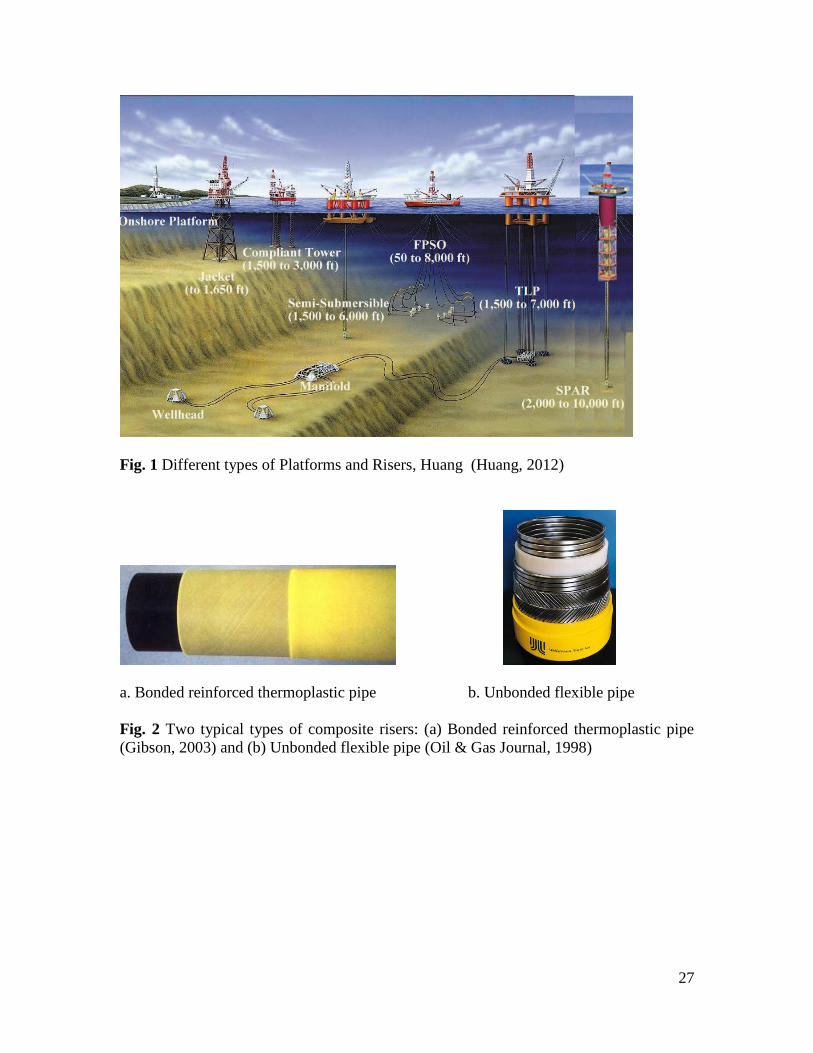
27
Fig. 1 Different types of Platforms and Risers, Huang (Huang, 2012)
a. Bonded reinforced thermoplastic pipe b. Unbonded flexible pipe
Fig. 2 Two typical types of composite risers: (a) Bonded reinforced thermoplastic pipe
(Gibson, 2003) and (b) Unbonded flexible pipe (Oil & Gas Journal, 1998)
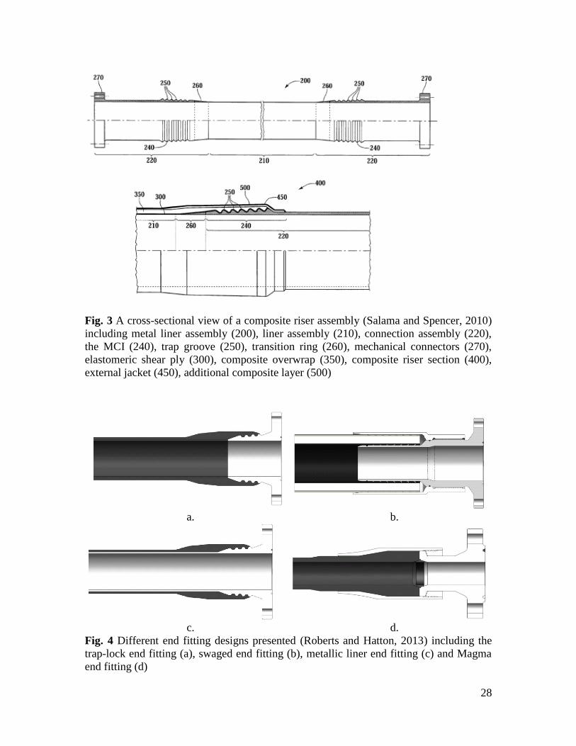
28
Fig. 3 A cross-sectional view of a composite riser assembly (Salama and Spencer, 2010)
including metal liner assembly (200), liner assembly (210), connection assembly (220),
the MCI (240), trap groove (250), transition ring (260), mechanical connectors (270),
elastomeric shear ply (300), composite overwrap (350), composite riser section (400),
external jacket (450), additional composite layer (500)
a. b.
c. d.
Fig. 4 Different end fitting designs presented (Roberts and Hatton, 2013) including the
trap-lock end fitting (a), swaged end fitting (b), metallic liner end fitting (c) and Magma
end fitting (d)

29
Steel pipe Composite layers
Fig. 5 FE local model of riser joint
Autofrettage Factory acceptance test
Hoop fiber
Axial fiber
Fig. 6 Stress-strain responses of the steel and composite pipes for different tests

30
Fig. 7 Compression stress in the steel pipe

31
Relative position to the open end of the tube body
MCI end0
Stre
ss in
co
mp
osi
te la
yer
(ksi
)
Fig. 8 Hoop stress in composite layers at relative position from the open plane
Table 1. Typical composite riser wall specification (Kim, 2007)
Overall Inner diameter (in) 9.72
Outer diameter (in) 12.414
Internal Liner Thickness (in) 0.25
Structural Composite Thickness 0.972
Cross-Sectional Area (in2) 34.176
External Liner Thickness (in) 0.125
Carbon-Epoxy
Composite Laminate
Layer 1 (880) thickness (in) 0.081
Layer 2 (00) thickness (in) 0.045
Layer 3 (880) thickness (in) 0.081
Layer 4 (00) thickness (in) 0.045
Layer 5 (880) thickness (in) 0.081
Layer 6 (00) thickness (in) 0.045
Layer 7 (880) thickness (in) 0.081
Layer 8 (00) thickness (in) 0.045
Layer 9 (880) thickness (in) 0.0405
Layer 10 (00) thickness (in) 0.045
Layer 11 (880) thickness (in) 0.0405
Layer 12 (00) thickness (in) 0.045
Layer 13 (880) thickness (in) 0.0405

32
Layer 14 (00) thickness (in) 0.045
Layer 15 (880) thickness (in) 0.0405
Layer 16 (00) thickness (in) 0.045
Layer 17 (880) thickness (in) 0.0405
Layer 18 (00) thickness (in) 0.045
Layer 19 (880) thickness (in) 0.0405
Table 2. Examples of Categorization of Loads, adapted from DNV (Det Norske
Veritas, 2010b)
Functional Loads Accidental Loads
Weight and buoyancy of riser, tubing,
coatings, marine growth, anodes,
buoyancy modules, contents and
attachments.
Weight of internal fluid.
Applied Tension for top-tension risers
Installation induced residual loads or
pre-stressing.
Pre-load of connectors.
Applied displacements and guidance
loads, including active positioning of
support floater.
Thermal loads.
Soil pressure on buried risers.
Differential Settlements.
Loads from drilling operations.
Construction loads and loads caused by
tools.
Fires and explosions
Impact/collisions: o riser collisions
o impact from dropped objects and
anchors
o impact from floater/floating objects
Hook/snag loads: o dragging anchor
Failure of support systems: o heave compensating system
malfunction (loss or stuck),
o loss of buoyancy,
o loss of mooring line or tendon
o dynamic positioning (DP) failure
o disconnect of Lower Marine Riser
package
Exceedence of internal overpressure: o loss of pressure safety system
o failure of well tubing or packers,
etc.
o pressure surge
o well kill – bullheading
Environmental events: o earthquake
o tsunamis
o iceberg
Pressure Loads Environmental Loads
External Hydrostatic pressure
Internal fluid pressure: hydrostatic,
static and dynamic contributions
Water Level
Waves
Internal waves and other effects due to
difference in water density
Current
Earthquake
Ice
Floater motions induced by wind,
waves and current i.e.: o Mean offset including steady wave

33
drift, wind and current forces
o Wave frequency motions
o Low frequency motions
Table 3. Key Design Load Cases, Hill et al. (Hill et al., 2006)
Total Net
Buoyancy (tons)
Maximum Riser
Tension (tons)
Buoyancy Close Distribution with maximum
Buoyancy Module of 3100 ft
275 300
Buoyancy Loose Distribution with maximum
Buoyancy Module of 7200 ft
425 135
Hoop Utilization Tensile
Utilization
Factory Acceptance test:
- No Tension
- Internal Pressure: 1.5 times of Design Pressure
0.91 0.91
Collapse of the internal carcass layer:
- Flooded pipe annulus
- Internal pressure = atmospheric
0.85 N/A
Extreme Operation:
- 100 year wave, 100 year current
- Design Pressure
0.85 0.67
Table 4. Summary of experimental programs on composite risers
Test modes
Small-Scale riser testing Large-Scale riser testing
Buckling/
Collapse tests
Gibson (Gibson, 2003)
Ramirez and Engelhardt (Ramirez
and Engelhardt, 2009)
Flexure/Tension Grant (Grant and Bradley,
1995)
Ochoa (Ochoa and Ross, 1998)
Rodriguez and Ochoa
(Rodriguez and Ochoa, 2004)
Sparks et al. (Sparks et al., 1998)
Gibson (Gibson, 2003)
Thomas (Thomas, 2004)
Axisymmetric
Burst Gibson (Gibson, 2003)
Fatigue tests Soden et al. (Soden et al.,
1993),
Ellyin et al. (Ellyin et al., 1997)
Ellyin and Martens (Ellyin and
Martens, 2001)
Mertiny et al. (Mertiny et al.,
Salama et al. (Salama et al., 1998)
Sparks et al. (Sparks et al., 1998)
Salama et al. (Salama et al., 2002)
Thomas (Thomas, 2004),
Cederberg(Cederberg, 2011)
Huybrechts (Huybrechts, 2002)

34
2004)
Chouchaoui and Ochoa
(Chouchaoui and Ochoa, 1999;
Chouchaoui et al., 1999)
Lindsey and Masudi (Lindsey
and Masudi, 1999)
Gibson (Gibson, 2003)
Rodriguez and Ochoa
(Rodriguez and Ochoa, 2004);
Application
based
Sobrinho et al. (Sobrinho et al.,
2010)
Table 5. Summary of mechanics and numerical analysis methods for composite
risers
Analysis
modes
Analytical approaches 2D FEA 3D FEA
Buckling/
Collapse
analysis
Brazier (Brazier, 1927)
Seide and Weingarten
(Seide and Weingarten,
1961)
Reissner and Weinitschke
(Reissner and Weinitschke,
1962)
Cheng and Ugural (Cheng
and Ugural, 1968)
Axelrad (Axelrad, 1965,
1987)
Corona et al. (Corona and
Rodrigues, 1995)
Silva et al. (Silva et al.,
2013)
Theotokoglou
(Theotokoglou, 2006)
Delamination Timoshenko and Gere
(Timoshenko and Gere,
1961)
Kachanov (Kachanov,
1988)
Wiggenraad et al.
(Wiggenraad et al., 1996)
Bai et al. (Bai et al., 1997)
Zhao et al. (Zhao et al.,
2000)
Rasheed and Tassoulas
(Rasheed and Tassoulas,
Tafreshi (Tafreshi,
2004)
Theotokoglou
(Theotokoglou, 2006)
Marinucci and de
Andrade (Marinucci
and de Andrade, 2006)
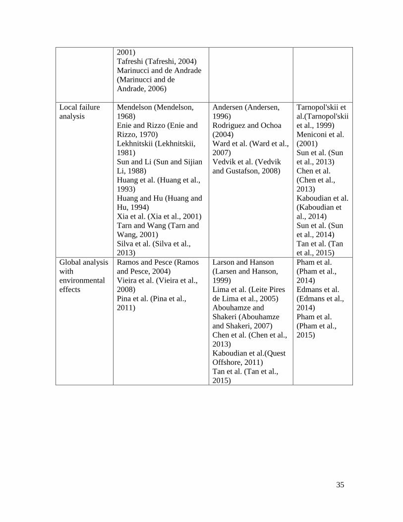
35
2001)
Tafreshi (Tafreshi, 2004)
Marinucci and de Andrade
(Marinucci and de
Andrade, 2006)
Local failure
analysis
Mendelson (Mendelson,
1968)
Enie and Rizzo (Enie and
Rizzo, 1970)
Lekhnitskii (Lekhnitskii,
1981)
Sun and Li (Sun and Sijian
Li, 1988)
Huang et al. (Huang et al.,
1993)
Huang and Hu (Huang and
Hu, 1994)
Xia et al. (Xia et al., 2001)
Tarn and Wang (Tarn and
Wang, 2001)
Silva et al. (Silva et al.,
2013)
Andersen (Andersen,
1996)
Rodriguez and Ochoa
(2004)
Ward et al. (Ward et al.,
2007)
Vedvik et al. (Vedvik
and Gustafson, 2008)
Tarnopol'skii et
al.(Tarnopol'skii
et al., 1999)
Meniconi et al.
(2001)
Sun et al. (Sun
et al., 2013)
Chen et al.
(Chen et al.,
2013)
Kaboudian et al.
(Kaboudian et
al., 2014)
Sun et al. (Sun
et al., 2014)
Tan et al. (Tan
et al., 2015)
Global analysis
with
environmental
effects
Ramos and Pesce (Ramos
and Pesce, 2004)
Vieira et al. (Vieira et al.,
2008)
Pina et al. (Pina et al.,
2011)
Larson and Hanson
(Larsen and Hanson,
1999)
Lima et al. (Leite Pires
de Lima et al., 2005)
Abouhamze and
Shakeri (Abouhamze
and Shakeri, 2007)
Chen et al. (Chen et al.,
2013)
Kaboudian et al.(Quest
Offshore, 2011)
Tan et al. (Tan et al.,
2015)
Pham et al.
(Pham et al.,
2014)
Edmans et al.
(Edmans et al.,
2014)
Pham et al.
(Pham et al.,
2015)