a review of airside heat transfer augmentation …...energies review a review of airside heat...
TRANSCRIPT
energies
Review
A Review of Airside Heat Transfer Augmentationwith Vortex Generators on Heat Transfer Surface
Lei Chai * and Savvas A. Tassou
RCUK Centre for Sustainable Energy Use in Food Chains (CSEF), Institute of Energy Futures, Brunel UniversityLondon, Uxbridge, Middlesex UB8 3PH, UK; [email protected]* Correspondence: [email protected]; Tel.: +44-189-526-5834
Received: 13 September 2018; Accepted: 10 October 2018; Published: 12 October 2018
Abstract: Heat exchanger performance can be improved via the introduction of vortex generators tothe airside surface, based on the mechanism that the generated longitudinal vortices can disrupt theboundary layer growth, increase the turbulence intensity and produce secondary fluid flows over theheat transfer surfaces. The key objective of this paper is to provide a critical overview of publishedworks relevant to such heat transfer surfaces. Different types of vortex generator are presented,and key experimental techniques and numerical methodologies are summarized. Flow phenomenaassociated with vortex generators embedded, attached, punched or mounted on heat transfer surfacesare investigated, and the thermohydraulic performance (heat transfer and pressure drop) of fourdifferent heat exchangers (flat plate, finned circular-tube, finned flat-tube and finned oval-tube) withvarious vortex-generator geometries, is discussed for different operating conditions. Furthermore,the thermohydraulic performance of heat transfer surfaces with recently proposed vortex generatorsis outlined and suggestions on using vortex generators for airside heat transfer augmentation arepresented. In general, the airside heat transfer surface performance can be substantially enhancedby vortex generators, but their impact can also be significantly influenced by many parameters,such as Reynolds number, tube geometry (shape, diameter, pitch, inline/staggered configuration),fin type (plane/wavy/composite, with or without punched holes), and vortex-generator geometry(shape, length, height, pitch, attack angle, aspect ratio, and configuration). The finned flat-tubeand finned oval-tube heat exchangers with recently proposed vortex generators usually show betterthermohydraulic performance than finned circular tube heat exchangers. Current heat exchangeroptimization approaches are usually based on the thermohydraulic performance alone. However,to ensure quick returns on investment, heat exchangers with complex geometries and surfacevortex generators, should be optimized using cost-based objective functions that consider thethermohydraulic performance alongside capital cost, running cost of the system as well as safety andcompliance with relevant international standards for different applications.
Keywords: heat transfer augmentation; pressure-drop penalty; heat transfer surface; vortex generators
1. Introduction
Heat exchangers are used for heat transfer between two or more fluids with temperature difference,which are widely used in many diverse industries and applications, including the process and chemicalindustries, transportation, air conditioning and refrigeration [1]. High-efficiency heat exchangers canreduce the fluid inventory, cost of materials and energy consumption, leading to increased efficiencyand return on investment, and lower environmental impacts. Significant research has been carried outto date on improving heat exchanger performance since the first published paper on the subject byJoule in 1861 [2]. For the typical applications of an air-cooled heat exchanger, due to the inherentlylower thermal conductivity of gas, and thus the lower heat transfer coefficient, than that of liquid
Energies 2018, 11, 2737; doi:10.3390/en11102737 www.mdpi.com/journal/energies
Energies 2018, 11, 2737 2 of 45
or two-phase flow, the airside resistance generally accounts for 85% or more of the total thermalresistance. To improve performance to meet the demands for high efficiency and low cost, the mostcommon way is to use heat transfer surfaces those are periodically interrupted along the streamwisedirection [3,4]. Some typical examples are heat transfer surfaces mounted with louvred fin, offsetfin, offset strip fin, rectangular plate-fin, and vortex generators (VGs) such as fins, ribs and wings.Their mechanisms for heat transfer augmentation are usually to disrupt the boundary layer growth, toincrease the turbulence intensity, and to generate secondary flows such as swirl or vortices [5–7].
These interrupted surfaces can significantly improve the heat transfer performance, but are usuallyassociated with a high pressure-drop penalty. In contrast to the main-flow-interrupted enhancementsurfaces with louvres or strip fins, the secondary-flow-interrupted ones with VGs not only improvethe heat transfer performance but also offer comparatively low pressure drop [6–9]. These advantagesmake them suitable for industrial thermal energy recovery systems, where, the high-pressure fluidflows inside the channels or tubes, and the high-temperature low pressure exhaust gas flows acrossthe channels or tubes [10,11]. However, VGs also lead to complex flow through heat transfer surfaces,with heat transfer enhancement becoming dependent on many important length scales and geometricfeatures [12]. Therefore, a deeper understanding of the thermohydraulic performance of heat transfersurfaces with VGs is needed to enable designers to assess the feasibility and viability of vortex-inducedairside heat transfer enhancement for specific applications.
To contribute to this effort, this paper presents a critical review of published works on thethermohydraulic performance of heat transfer surfaces with different VGs, with the purpose ofdeveloping a systematic evaluation of vortex-induced airside heat transfer enhancement. Different VGenhancement methods are presented for four different heat transfer surfaces, including VGs on flatplates, VGs in finned circular-tube heat exchangers, VGs in finned flat-tube heat exchangers and VGs infinned oval-tube heat exchangers, and their flow and heat transfer interactions are carefully analyzedunder different operating conditions. The effects of operating conditions and various design parameterson thermohydraulic performance, particularly for the heat transfer surfaces with recently proposedVGs, are demonstrated with the goal of contributing to an improved understanding of heat exchangerdesigns, with a view to developing higher-performance heat transfer surfaces—particularly forapplications with specific constraints on size and extreme limitations on thermohydraulic performance.
2. Vortex Generators
As constructional details, heat exchangers are classified into tubular heat exchangers, plate heatexchangers, extended surface heat exchangers and regenerators [1]. Plate-fin heat exchangers andfinned-tube heat exchangers are the most common examples of extended surface heat exchangers.VGs are commonly used in the extended fin surface to further increase the heat transfer rate, whichenhance the heat transfer by interacting with and disturbing the thermal boundary layer between theheat exchanger surface and the secondary fluid flowing across the surface. Depending on the specificapplication, the VG devices differ in their geometry, dimensions and integration on the heat exchangersurface, leading to two main categories of generated vortex: transverse and longitudinal. Generally,the longitudinal vortices are more effective than transverse vortices in enhancing heat transfer withonly a small increase in pressure drop [13]. Four surface protrusion designs are commonly used forlongitudinal-vortex-induced heat transfer enhancement. As shown in Figure 1, they are delta wing,rectangular wing, delta winglet and rectangular winglet [8,12,14]. The geometry parameters of theseVGs, such as the angle of attack (α) and aspect ratio (Λ), can have a significant influence on their heattransfer capability, and have thus received increased research attention.

Energies 2018, 11, 2737 3 of 45Energies 2018, 11, x FOR PEER REVIEW 3 of 41
Figure 1. Common vortex generators and the associated geometrical definitions [8,12,14].
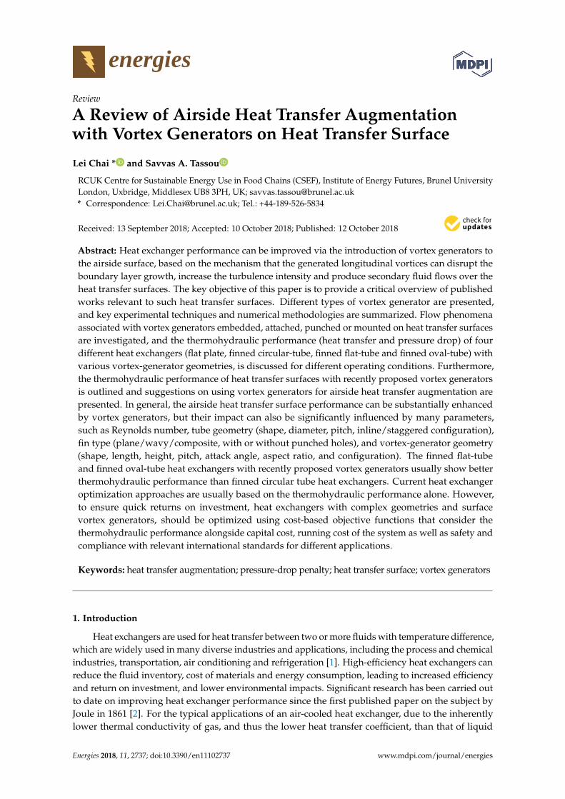
Alongside the four main types, several other VGs have been proposed and investigated in recent years. Wang et al. [6,9], Lin et al. [15] and Gong et al. [16] proposed annular winglets and wave-element VGs, as shown in Figure 2a, particularly for application to finned-tube heat exchangers. He et al. [17] proposed V-deployed VG arrays, as shown in Figure 2b, to emulate locomotion of animals in nature. Zhou et al. [18,19] investigated several straight- and curved-surface winglet VGs with or without punched holes, namely: rectangular winglet, trapezoidal winglet, delta winglet, curved rectangular winglet, curved trapezoidal winglet and curved delta winglet, as shown in Figure 2c, respectively abbreviated as RW, TW, DW, CRW, CTW and CDW. Lotfi et al. [20,21] considered the application of four different VG types on smooth wavy-finned oval-tube heat exchangers, as shown in Figure 2d, which were the rectangular trapezoidal winglet, angle rectangular winglet, curved angle rectangular winglet and wheeler wishbone, respectively abbreviated as RTW, ARW, CARW and WW. Wu et al. [22] proposed composite fin designs incorporating VGs on slit fins, as shown in Figure 2e. All the newly proposed VGs demonstrate improvements to the thermohydraulic performance of the heat exchangers. Of particular note is the novel longitudinal tube fin designs proposed by Stehlík et al. [10], shown in Figure 2f, which provides the heat transfer intensification through the increased heat transfer area and the flow turbulence, and could have the applications in heat recovery in power plants, where fin geometry and enhancement can effectively reduce the heat exchanger size and costs.
(a) (b) (c)
Figure 1. Common vortex generators and the associated geometrical definitions [8,12,14].
Alongside the four main types, several other VGs have been proposed and investigated in recentyears. Wang et al. [6,9], Lin et al. [15] and Gong et al. [16] proposed annular winglets and wave-elementVGs, as shown in Figure 2a, particularly for application to finned-tube heat exchangers. He et al. [17]proposed V-deployed VG arrays, as shown in Figure 2b, to emulate locomotion of animals in nature.Zhou et al. [18,19] investigated several straight- and curved-surface winglet VGs with or withoutpunched holes, namely: rectangular winglet, trapezoidal winglet, delta winglet, curved rectangularwinglet, curved trapezoidal winglet and curved delta winglet, as shown in Figure 2c, respectivelyabbreviated as RW, TW, DW, CRW, CTW and CDW. Lotfi et al. [20,21] considered the application offour different VG types on smooth wavy-finned oval-tube heat exchangers, as shown in Figure 2d,which were the rectangular trapezoidal winglet, angle rectangular winglet, curved angle rectangularwinglet and wheeler wishbone, respectively abbreviated as RTW, ARW, CARW and WW. Wu et al. [22]proposed composite fin designs incorporating VGs on slit fins, as shown in Figure 2e. All the newlyproposed VGs demonstrate improvements to the thermohydraulic performance of the heat exchangers.Of particular note is the novel longitudinal tube fin designs proposed by Stehlík et al. [10], shown inFigure 2f, which provides the heat transfer intensification through the increased heat transfer areaand the flow turbulence, and could have the applications in heat recovery in power plants, where fingeometry and enhancement can effectively reduce the heat exchanger size and costs.
Energies 2018, 11, x FOR PEER REVIEW 3 of 41
Figure 1. Common vortex generators and the associated geometrical definitions [8,12,14].
Alongside the four main types, several other VGs have been proposed and investigated in recent years. Wang et al. [6,9], Lin et al. [15] and Gong et al. [16] proposed annular winglets and wave-element VGs, as shown in Figure 2a, particularly for application to finned-tube heat exchangers. He et al. [17] proposed V-deployed VG arrays, as shown in Figure 2b, to emulate locomotion of animals in nature. Zhou et al. [18,19] investigated several straight- and curved-surface winglet VGs with or without punched holes, namely: rectangular winglet, trapezoidal winglet, delta winglet, curved rectangular winglet, curved trapezoidal winglet and curved delta winglet, as shown in Figure 2c, respectively abbreviated as RW, TW, DW, CRW, CTW and CDW. Lotfi et al. [20,21] considered the application of four different VG types on smooth wavy-finned oval-tube heat exchangers, as shown in Figure 2d, which were the rectangular trapezoidal winglet, angle rectangular winglet, curved angle rectangular winglet and wheeler wishbone, respectively abbreviated as RTW, ARW, CARW and WW. Wu et al. [22] proposed composite fin designs incorporating VGs on slit fins, as shown in Figure 2e. All the newly proposed VGs demonstrate improvements to the thermohydraulic performance of the heat exchangers. Of particular note is the novel longitudinal tube fin designs proposed by Stehlík et al. [10], shown in Figure 2f, which provides the heat transfer intensification through the increased heat transfer area and the flow turbulence, and could have the applications in heat recovery in power plants, where fin geometry and enhancement can effectively reduce the heat exchanger size and costs.
(a) (b) (c)
Figure 2. Cont.
Energies 2018, 11, 2737 4 of 45Energies 2018, 11, x FOR PEER REVIEW 4 of 41
(d) (e) (f)
Figure 2. Recently proposed vortex generators (VGs). (a) Annular winglet and wave-element VGs [6,9,15,16]. (b) V-deployed VG array [17]. (c) Curved winglet VGs with or without punched holes [18,19]. (d) Wavy fin and oval-tube bank with mounted VGs [20,21]. (e) Composite fin with VGs and slit fin [22]. (f) Longitudinally finned tubes by Stehlík et al. [10].
3. Experimental and Numerical Methods
3.1. Experiment Techniques
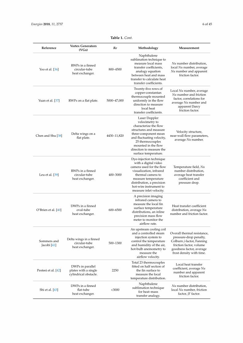
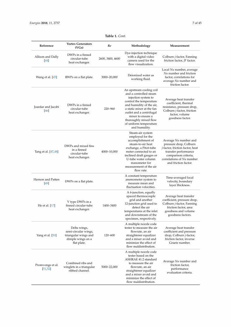
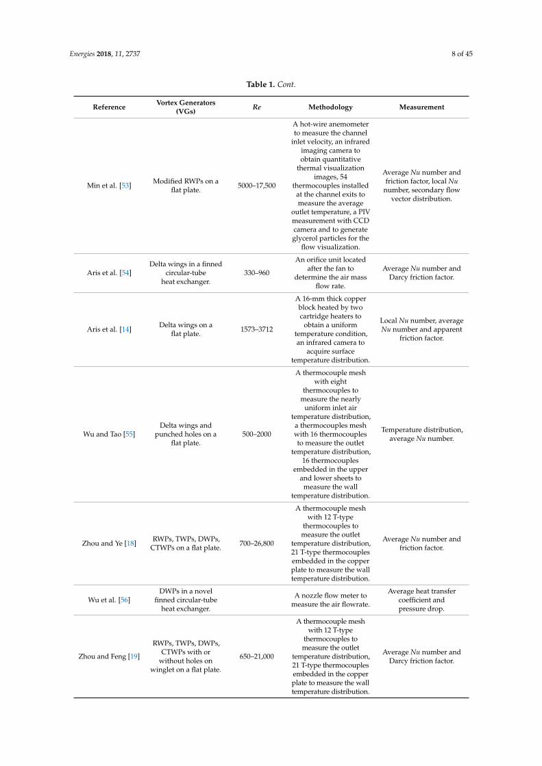
Experimentation is so important in engineering and science that the researchers should be familiar with the measurement methods and the analysis techniques for data reduction. Measurement of thermohydraulic performance frequently require accurate flow rate, pressure and temperature measurements. The experiment techniques investigating the thermohydraulic performance of the airside heat transfer surfaces include laser light sheets (LLS), laser doppler velocimetry (LDV), hot-wire anemometry, particle image velocimetry (PIV), liquid crystal thermography (LCT), the naphthalene sublimation technique and infrared thermography. Table 1 indicates the representative experiment techniques for flow rate, pressure and temperature measurements in chronological order. These experiment techniques commonly concentrate on the extended fin surfaces, regardless of the tube type of heat exchanger, and one technique can be used for different heat transfer surfaces and different VGs; therefore, these techniques are not separately presented based on the types of either the tube or the VGs. In this section, we seek to demonstrate the experimental methods and show the generalized experimental systems, and pay particular attention to the measurements of flow visualization and temperature distribution, because they are very important for a deeper understanding of flow and heat transfer interactions.
Table 1. Representative experimental investigations of airside thermohydraulic performance with vortex generators on heat transfer surfaces.
Reference Vortex Generators
(VGs) Re Methodology Measurement
Garimella and Eibeck [23]
Two different half-delta wings in a
horizontal channel.
700–5200
An array of 30 heated copper elements mounted on the
detachable hatch in six spanwise rows for heat
transfer.
Heat transfer enhancement, pressure drop.
Fiebig et al. [24] Delta and
rectangular wings on a flat plate.
1360–2270
A laser light sheet used for the flow visualization, unsteady liquid crystal
thermography to determine the local heat transfer
coefficients.
Flow pattern, local heat transfer coefficient, drag
coefficient, Colburn j-factor, normalized heat transfer
enhancement.
Tiggelbeck et al. [25,26]
Single and double rows of half-delta
wings on a flat plate.
1600–8000
Tracer particles of evaporating glycerine used for observations of the flow
structure, laser light sheets to observe the visible flow field, a liquid crystal thermography
used for local heat transfer measurements.
Flow pattern and vortex property, local Nu number,
average Nu number and drag coefficient.
Figure 2. Recently proposed vortex generators (VGs). (a) Annular winglet and wave-elementVGs [6,9,15,16]. (b) V-deployed VG array [17]. (c) Curved winglet VGs with or without punchedholes [18,19]. (d) Wavy fin and oval-tube bank with mounted VGs [20,21]. (e) Composite fin with VGsand slit fin [22]. (f) Longitudinally finned tubes by Stehlík et al. [10].
3. Experimental and Numerical Methods
3.1. Experiment Techniques
Experimentation is so important in engineering and science that the researchers should befamiliar with the measurement methods and the analysis techniques for data reduction. Measurementof thermohydraulic performance frequently require accurate flow rate, pressure and temperaturemeasurements. The experiment techniques investigating the thermohydraulic performance of theairside heat transfer surfaces include laser light sheets (LLS), laser doppler velocimetry (LDV),hot-wire anemometry, particle image velocimetry (PIV), liquid crystal thermography (LCT), thenaphthalene sublimation technique and infrared thermography. Table 1 indicates the representativeexperiment techniques for flow rate, pressure and temperature measurements in chronological order.These experiment techniques commonly concentrate on the extended fin surfaces, regardless of the tubetype of heat exchanger, and one technique can be used for different heat transfer surfaces and differentVGs; therefore, these techniques are not separately presented based on the types of either the tube orthe VGs. In this section, we seek to demonstrate the experimental methods and show the generalizedexperimental systems, and pay particular attention to the measurements of flow visualization andtemperature distribution, because they are very important for a deeper understanding of flow andheat transfer interactions.
Table 1. Representative experimental investigations of airside thermohydraulic performance withvortex generators on heat transfer surfaces.
Reference Vortex Generators(VGs) Re Methodology Measurement
Garimella andEibeck [23]
Two differenthalf-delta wings in ahorizontal channel.
700–5200
An array of 30 heatedcopper elementsmounted on the
detachable hatch in sixspanwise rows for
heat transfer.
Heat transferenhancement,pressure drop.
Fiebig et al. [24] Delta and rectangularwings on a flat plate. 1360–2270
A laser light sheet usedfor the flow
visualization, unsteadyliquid crystal
thermography todetermine the local heat
transfer coefficients.
Flow pattern, local heattransfer coefficient, drag
coefficient, Colburnj-factor, normalized heattransfer enhancement.

Energies 2018, 11, 2737 5 of 45
Table 1. Cont.
Reference Vortex Generators(VGs) Re Methodology Measurement
Tiggelbeck et al.[25,26]
Single and doublerows of half-delta
wings on a flat plate.1600–8000
Tracer particles ofevaporating glycerine
used for observations ofthe flow structure, laserlight sheets to observethe visible flow field, a
liquid crystalthermography used for
local heattransfer measurements.
Flow pattern and vortexproperty, local Nu number,
average Nu number anddrag coefficient.
Fiebig et al. [27]DWPs in a finned
circular-tubeheat exchanger.
600–2700
A hot-wire anemometerat 2 mm intervals to
measure the axialvelocity, a liquid crystalthermography used for
local heattransfer measurements.
Nu number distribution,local Nu number, averageNu number and apparent
friction factor.
Tiggelbeck et al.[28]
Delta wing,rectangular wing,
DWPs and RWPs on aflat plate.
2000–9000
A thermochromic liquidcrystal thermography tomeasure the local heattransfer on the wall.
Local Nu number.
Fiebig et al. [29]DWPs in finned
circular and flat-tubeheat exchangers.
600–3000
A liquid crystalthermography used for
local heattransfer measurements.
Nu number distribution,local Nu number, averageNu number and apparent
friction factor.
Gentry and Jacobi[30]
Delta wings on aflat plate. 600, 800, 1000
A laser light sheet usedfor flow visualization,
naphthalene sublimationexperiments to provideconvection coefficients.
Sherwood number,drag coefficient.
Kotcioglu et al. [31] RWPs on a flat plate. 3000–30,000
A smoke generator usedfor laminar main flow
visualization in aHele–Shaw apparatus.
Flow pattern, average Nunumber and friction factor.
Wang et al. [6,9]
Interrupted annularand delta winglets in a
finned circular-tubeheat exchanger.
500, 1500, 3300
Water tunnel apparatusused to visualize the
flow pattern, adye-injection technique
with a digital videocamera used for theflow visualization.
Flow pattern.
Torii et al. [32–34]DWPs in a finned
circular-tubeheat exchanger.
350–2100
A stainless steel ribbonheating screen uniformly
spread over an entirecross section at the inletof the test section to heat
the flow quicklyand uniformly.
Colburn j-factor,friction factor.
Gentry and Jacobi[35]
Delta wings on aflat plate. 300–2000
A laser light sheet usedfor flow visualization,
naphthalene sublimationexperiments to provide
convection coefficients, avane-type vortex meter
and a potential-flowmodel with flow
visualization to infervortex strength.
Flow pattern,dimensionless vortexcirculation, Sherwoodnumber distribution,average Sherwood
number, heat transferenhancement,
pressure-drop penalty.
Energies 2018, 11, 2737 6 of 45
Table 1. Cont.
Reference Vortex Generators(VGs) Re Methodology Measurement
Yoo et al. [36]RWPs in a finned
circular-tubeheat exchanger.
800–4500
Naphthalenesublimation technique to
measure local masstransfer coefficients,
analogy equationbetween heat and mass
transfer to calculate heattransfer coefficients.
Nu number distribution,local Nu number, averageNu number and apparent
friction factor.
Yuan et al. [37] RWPs on a flat plate. 5000–47,000
Twenty-five rows ofcopper-constantan
thermocouple mounteduniformly in the flowdirection to measure
local heattransfer coefficients.
Local Nu number, averageNu number and frictionfactor, correlations for
average Nu number andapparent Darcyfriction factor.
Chen and Shu [38] Delta wings on aflat plate. 4430–11,820
Laser Dopplervelocimetry to
characterize the flowstructures and measurethree-component meanand fluctuating velocity,
25 thermocouplesmounted in the flow
direction to measure thesurface temperature.
Velocity structure,near-wall flow parameters,
average Nu number.
Leu et al. [39]RWPs in a finned
circular-tubeheat exchanger.
400–3000
Dye-injection techniquewith a digital video
camera used for the flowvisualization, infrared
thermal camera tomeasure temperature
distribution, a precisionhot-wire instrument tomeasure inlet velocity.
Temperature field, Nunumber distribution,average heat transfer
coefficient andpressure drop.
O’Brien et al. [40]DWPs in a finned
oval-tubeheat exchanger.
600–6500
A precision imaginginfrared camera to
measure the local finsurface temperature
distributions, an inlineprecision mass flowmeter to monitor the
airflow rate.
Heat transfer coefficientdistribution, average Nu
number and friction factor.
Sommers andJacobi [41]
Delta wings in a finnedcircular-tube
heat exchanger.500–1300
An upstream cooling coiland a controlled steam
injection system tocontrol the temperatureand humidity of the air,hot-bulb anemometry to
measure theairflow velocity.
Overall thermal resistance,pressure-drop penalty,
Colburn j-factor, Fanningfriction factor, volume
goodness factor, averagefrost density with time.
Pesteei et al. [42]DWPs in parallel
plates with a singlecylindrical obstacle.
2250
Total 23 thermocouplesfitted on half section of
the fin surface tomeasure the local
temperature distribution.
Local heat transfercoefficient, average Nunumber and apparent
friction factor.
Shi et al. [43]DWPs in a finned
flat-tubeheat exchanger.
<3000
Naphthalenesublimation technique
for heat–masstransfer analogy.
Nu number distribution,local Nu number, friction
factor, JF factor.
Energies 2018, 11, 2737 7 of 45
Table 1. Cont.
Reference Vortex Generators(VGs) Re Methodology Measurement
Allison and Dally[44]
DWPs in a finnedcircular-tube
heat exchanger.2600, 3400, 4600
Dye-injection techniquewith a digital videocamera used for theflow visualization.
Colburn j-factor, Fanningfriction factor, JF factor.
Wang et al. [45] RWPs on a flat plate. 3000–20,000 Deionized water asworking fluid.
Local Nu number, averageNu number and frictionfactor, correlations for
average Nu number andfriction factor.
Joardar and Jacobi[46]
DWPs in a finnedcircular-tube
heat exchanger.220–960
An upstream cooling coiland a controlled steam
injection system tocontrol the temperatureand humidity of the air,a static mixer at the fanoutlet and a centrifugal
mixer to ensure athoroughly mixed flowof uniform temperature
and humidity.
Average heat transfercoefficient, thermal
resistance, pressure drop,Colburn j-factor, friction
factor, volumegoodness factor.
Tang et al. [47,48]
DWPs and mixed finsin a finned
circular-tubeheat exchanger.
4000–10,000
Steam-air systememployed for the
accomplishment ofsteam-to-air heat
exchange, a Pitot-tubemeter connected to an
inclined draft gauges orU-tube water column
manometer formeasurement of the air
flow rate.
Average Nu number andpressure drop, Colburn
j-factor, friction factor, heattransfer performancecomparison criteria,
correlations of Nu numberand friction factor.
Hernon and Patten[49] DWPs on a flat plate.
A constant temperatureanemometer system to
measure mean andfluctuation velocities.
Time-averaged localvelocity, boundary
layer thickness.
He et al. [17]V type DWPs in a
finned circular-tubeheat exchanger.
1400–3400
A 6-junction, equallyspaced thermocouple
grid and another12-junction grid used to
detect the airtemperatures at the inletand downstream of thespecimen, respectively.
Average heat transfercoefficient, pressure drop,Colburn j-factor, Fanning
friction factor, areagoodness and volume
goodness factors.
Yang et al. [50]
Delta wings,semi-circular wings,
triangular wings anddimple wings on a
flat plate.
120–600
A multiple nozzle codetester to measure the air
flowrate, an airstraightener equalizerand a mixer avoid andminimize the effect offlow maldistribution.
Average heat transfercoefficient and pressuredrop, Colburn j-factor,friction factor, inverse
Graetz number.
Promvonge et al.[51,52]
Combined ribs andwinglets in a triangular
ribbed channel.5000–22,000
A multiple nozzle codetester based on the
ASHRAE 41.2 standardto measure the air
flowrate, an airstraightener equalizerand a mixer avoid andminimize the effect offlow maldistribution.
Average Nu number andfriction factor,performance
evaluation criteria.
Energies 2018, 11, 2737 8 of 45
Table 1. Cont.
Reference Vortex Generators(VGs) Re Methodology Measurement
Min et al. [53] Modified RWPs on aflat plate. 5000–17,500
A hot-wire anemometerto measure the channel
inlet velocity, an infraredimaging camera toobtain quantitative
thermal visualizationimages, 54
thermocouples installedat the channel exits tomeasure the average
outlet temperature, a PIVmeasurement with CCDcamera and to generateglycerol particles for the
flow visualization.
Average Nu number andfriction factor, local Nu
number, secondary flowvector distribution.
Aris et al. [54]Delta wings in a finned
circular-tubeheat exchanger.
330–960
An orifice unit locatedafter the fan to
determine the air massflow rate.
Average Nu number andDarcy friction factor.
Aris et al. [14] Delta wings on aflat plate. 1573–3712
A 16-mm thick copperblock heated by twocartridge heaters to
obtain a uniformtemperature condition,an infrared camera to
acquire surfacetemperature distribution.
Local Nu number, averageNu number and apparent
friction factor.
Wu and Tao [55]Delta wings and
punched holes on aflat plate.
500–2000
A thermocouple meshwith eight
thermocouples tomeasure the nearly
uniform inlet airtemperature distribution,a thermocouples meshwith 16 thermocouplesto measure the outlet
temperature distribution,16 thermocouples
embedded in the upperand lower sheets to
measure the walltemperature distribution.
Temperature distribution,average Nu number.
Zhou and Ye [18] RWPs, TWPs, DWPs,CTWPs on a flat plate. 700–26,800
A thermocouple meshwith 12 T-type
thermocouples tomeasure the outlet
temperature distribution,21 T-type thermocouplesembedded in the copperplate to measure the walltemperature distribution.
Average Nu number andfriction factor.
Wu et al. [56]DWPs in a novel
finned circular-tubeheat exchanger.
A nozzle flow meter tomeasure the air flowrate.
Average heat transfercoefficient andpressure drop.
Zhou and Feng [19]
RWPs, TWPs, DWPs,CTWPs with or
without holes onwinglet on a flat plate.
650–21,000
A thermocouple meshwith 12 T-type
thermocouples tomeasure the outlet
temperature distribution,21 T-type thermocouplesembedded in the copperplate to measure the walltemperature distribution.
Average Nu number andDarcy friction factor.
Energies 2018, 11, 2737 9 of 45
Table 1. Cont.
Reference Vortex Generators(VGs) Re Methodology Measurement
Wang et al. [57]
Semi-dimple wingletpairs in plain or louvre
finned circular-tubeheat exchanger.
A multiple nozzle codetester to measure the air
flowrate, an airstraightener equalizerand a mixer avoid andminimize the effect offlow maldistribution.
Average heat transfercoefficient andpressure drop.
Abdelatie et al. [58]RWPs in a
wing-shaped-tubes-bundleheat exchanger.
1850–9700
Eight thermocouples ontwo grids at the entranceand the exit to measure
inlet and outlet airaverage temperatures,
an alcohol thermometerwith wet wick
surrounded bulb tomeasure the wet bulb
temperatures at the inletand the exit.
Average Nu number anddrag coefficient.
Wu et al. [59]Curved DWPs in afinned circular-tube
heat exchanger.500–4200
Eight thermocouples ontwo grids at the entranceand the exit to measure
inlet and outlet airtemperatures, an alcoholthermometer with wet
wick surrounded bulb tomeasure the wet bulb
temperatures at the inletand the exit.
Average Nu number andfriction factor, averageheat transfer coefficientand pressure drop, JFfactor, correlations for
average Nu number andDarcy friction factor.
DWPs: delta winglet pairs; RWPs: rectangular winglet pairs; TWPs: trapezoidal winglet pairs; CTWPs: curvedtrapezoidal winglet pairs.
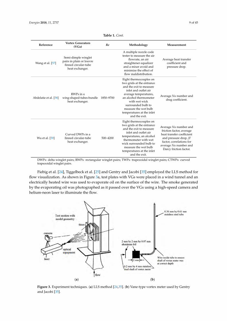
Fiebig et al. [24], Tiggelbeck et al. [25] and Gentry and Jacobi [35] employed the LLS method forflow visualization. As shown in Figure 3a, test plates with VGs were placed in a wind tunnel and anelectrically heated wire was used to evaporate oil on the surface of the wire. The smoke generatedby the evaporating oil was photographed as it passed over the VGs using a high-speed camera andhelium-neon laser to illuminate the flow.
Energies 2018, 11, x FOR PEER REVIEW 8 of 41
to measure the wall temperature distribution.
Wang et al. [57]
Semi-dimple winglet pairs in plain or louvre finned circular-
tube heat exchanger.
A multiple nozzle code tester to measure the air flowrate, an air straightener equalizer
and a mixer avoid and minimize the effect of flow
maldistribution.
Average heat transfer coefficient and pressure
drop.
Abdelatie et al. [58]
RWPs in a wing-shaped-tubes-
bundle heat exchanger.
1850–9700
Eight thermocouples on two grids at the entrance and the
exit to measure inlet and outlet air average
temperatures, an alcohol thermometer with wet wick surrounded bulb to measure the wet bulb temperatures at
the inlet and the exit.
Average Nu number and drag coefficient.
Wu et al. [59]
Curved DWPs in a finned circular-
tube heat exchanger.
500–4200
Eight thermocouples on two grids at the entrance and the
exit to measure inlet and outlet air temperatures, an
alcohol thermometer with wet wick surrounded bulb to
measure the wet bulb temperatures at the inlet and
the exit.
Average Nu number and friction factor, average heat
transfer coefficient and pressure drop, JF factor,
correlations for average Nu number and Darcy friction
factor.
DWPs: delta winglet pairs; RWPs: rectangular winglet pairs; TWPs: trapezoidal winglet pairs; CTWPs: curved trapezoidal winglet pairs.
Fiebig et al. [24], Tiggelbeck et al. [25] and Gentry and Jacobi [35] employed the LLS method for flow visualization. As shown in Figure 3a, test plates with VGs were placed in a wind tunnel and an electrically heated wire was used to evaporate oil on the surface of the wire. The smoke generated by the evaporating oil was photographed as it passed over the VGs using a high-speed camera and helium-neon laser to illuminate the flow.
(a) (b)
Figure 3. Experiment techniques. (a) LLS method [24,35]. (b) Vane-type vortex meter used by Gentry and Jacobi [35].
Wang et al. [6,9], Gentry and Jacobi [35], Leu et al. [39], Allison and Dally [44] and Wang et al. [45] performed flow visualization in a transparent water tunnel using the dye-injection technique.
Figure 3. Experiment techniques. (a) LLS method [24,35]. (b) Vane-type vortex meter used by Gentryand Jacobi [35].

Energies 2018, 11, 2737 10 of 45
Wang et al. [6,9], Gentry and Jacobi [35], Leu et al. [39], Allison and Dally [44] and Wang et al. [45]performed flow visualization in a transparent water tunnel using the dye-injection technique.The velocity in the water tunnel was measured by recording the time required for a dye markerto traverse a known distance. The vortex strength can be determined with two different techniques:by direct measurement, using the vane-type vortex meter as illustrated in Figure 3b, and apotential-flow model and flow visualization from the observed trajectories of the vortices at severalstreamwise locations from the leading edge.
Chen and Shu [38] conducted three-component mean and fluctuating velocity measurementsusing the LDV to obtain the near-wall axial mean velocity, axial vorticity and the correspondingturbulent kinetic energy for a heated plate installed at the bottom wall of a duct. A smoke wire waslocated upstream of the apparatus to generate sub-micron particles. Flow structure measurementswere conducted at four cross-sectional planes and two planes vertically perpendicular to the crosssection, and the near-wall axial vorticity was obtained from the mean component velocities.
Hernon and Patten [49] conducted hot-wire measurements to obtain the velocity profilesdownstream of a delta winglet pair (DWP) placed on an unheated flat surface. The mean andfluctuating velocities were measured by a TSI IFA300 constant temperature anemometer system, whichcan obtain the boundary layer profile shape and measure the boundary layer thickness. The authorshighlighted advantages of hot-wire measurements over other measurement techniques, these includedincreased temporal and spatial resolution, enabling further elucidation of critical flow features that canenhance understanding of the flow and heat transfer processes taking place.
Min et al. [53] applied the PIV measurement technique using glycerol particles with a chargedcoupled device (CCD) camera to carry out flow visualization on a heated flat plate. The glycerolparticle generator produced particles of approximately 1 µm in diameter and high concentration, sothat sufficient light could be scattered in the visualization domain for detection by the CCD camera.
Fiebig et al. [24,27,29] and Tiggelbeck et al. [25] used the transient LCT technique to investigatethe impact of longitudinal vortices on the local heat transfer coefficient. With this technique, a thin filmof liquid crystals was coated on the heat transfer surface and the development of specific isothermsduring transient heating was recorded using laser light and the property of thermochromic liquidcrystals to reflect incident monochromatic light from the laser only at specific temperatures.
Gentry and Jacobi [30], Yoo et al. [36] and Shi et al. [43] investigated the interactions between thevortex and boundary layer using naphthalene sublimation experimental techniques. During theexperiment, the Naphthalene formed part of the plate surface on solidification and polishing.The naphthalene surface can extend over the entire streamwise length of the plate and developa thin lip at the leading and trailing edges. The local sublimation depths were measured using anon-contact, optical technique (known as laser triangulation) to yield the local and average masstransfer coefficients, then to also find the local and average heat transfer coefficients through the heatand mass analogy.
O’Brien et al. [40] employed a transient technique for heat transfer measurements, in whicha heated airflow was suddenly introduced to the test section and the high-resolution local finsurface temperature distributions were obtained by an imaging infrared camera (FLIR PRISM DS).Leu et al. [39], Min et al. [53] and Aris et al. [14] also applied infrared thermography to measuresurface temperature distributions. This method presents several advantages over the thermochromicliquid crystals to measure the surface temperature distribution, which can be applied over a wideavailable temperature range, obtain high spatial resolution and excellent thermal resolution, andemploy full-field direct digital data acquisition and processing.
3.2. Numerical Methodology
Numerical modelling is a science that can be helpful for studying fluid flow and heat transfer bysolving mathematical equations. It has been proven an effective and reliable tool to provide detailedinsight into flow structure, velocity field, pressure distribution and temperature gradient at a lower

Energies 2018, 11, 2737 11 of 45
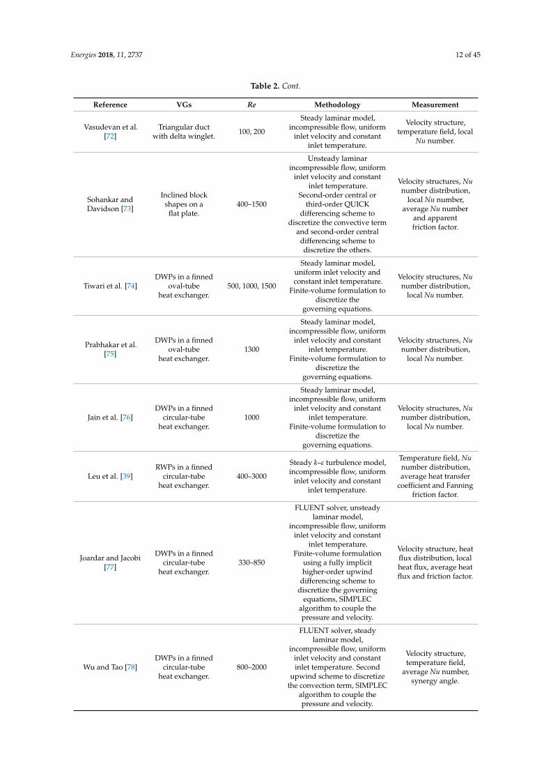
cost due to its reduced requirement for experiments [60,61], which is important for comprehensiveinvestigation of fluid flow and heat transfer interaction and novel VG design and optimization beforeprototype construction. Because the same numerical methodology can be used for different heattransfer surfaces, in this section we present the mentioned approaches, not according to the heatexchanger type, but the numerical aspects, e.g., solver, assumption, model, boundary condition,discretization, etc. Table 2 presents the key numerical methodology applied in the numerical studies ofthe published works in chronological order.
Table 2. Representative numerical studies of airside thermohydraulic performance with vortexgenerators on heat transfer surfaces.
Reference VGs Re Methodology Measurement
Fiebig et al. [62]Delta winglets ordelta wings on a
flat plate.500–2000
SOLA algorithm, unsteadylaminar model,
incompressible flow,hydrodynamically developed
inlet velocity and constantinlet temperature.
Velocity structure,temperature field.
Biswas et al. [63] Delta wings on aflat plate. 500–1815
Modified MAC algorithm,unsteady laminar model,
uniform inlet velocity andconstant inlet temperature.
Velocity structure,temperature field, local
Nu number andfriction factor.
Biswas et al. [64]Delta wings and
punched holes on aflat plate.
500–1815
Modified MAC algorithm,unsteady laminar model,
uniform inlet velocity andconstant inlet temperature.
Velocity structure,temperature field, local
Nu number andfriction factor.
Zhu et al. [65] DWPs on aflat plate. 67,000
SOLA algorithm, unsteady k–εturbulence model,
incompressible flow, inletvelocity component profile
from experiment.
Velocity structure.
Zhu et al. [66]
Delta wings,rectangular wings,DWPs and RWPs
on a flat plate.
50,000
SOLA algorithm, unsteady k–εturbulence model,
incompressible flow,hydrodynamically developed
inlet velocity and constantinlet temperature.
Velocity structure,temperature field, local
Nu number, averageNu number and
apparentfriction factor.
Biswas et al. [67]DWPs in a
circular-tubeheat exchanger.
500–1000
Modified MAC algorithm,unsteady laminar model, fullydeveloped inlet velocity andconstant inlet temperature.
Velocity structure,temperature field, local
Nu number.
Biswas et al. [68]Delta wings and
DWPs on aflat plate.
500–3000
Modified MAC algorithm,unsteady laminar model,
incompressible flow, uniforminlet velocity and constant
inlet temperature.
Velocity structure, localNu number and skinfriction coefficient.
Deb et al. [69] DWPs on aflat plate. 400–1000
Modified MAC algorithm,unsteady laminar model and
k–ε turbulence model,incompressible flow.
Velocity structure, localNu number and skinfriction coefficient.
Biswas et al. [70] Delta winglets on aflat plate. 1580
Modified MAC algorithm,unsteady laminar model, fullydeveloped inlet velocity andconstant inlet temperature.
Velocity structure, localNu number andquality factor.
Chen et al. [71]
Punched deltawinglets in a
finned oval-tubeheat exchanger.
300
Steady laminar model,incompressible flow, fully
developed inlet velocity andconstant inlet temperature.
Velocity structure,temperature field,
pressure distributions,local Nu number and
pressure drop.
Energies 2018, 11, 2737 12 of 45
Table 2. Cont.
Reference VGs Re Methodology Measurement
Vasudevan et al.[72]
Triangular ductwith delta winglet. 100, 200
Steady laminar model,incompressible flow, uniform
inlet velocity and constantinlet temperature.
Velocity structure,temperature field, local
Nu number.
Sohankar andDavidson [73]
Inclined blockshapes on a
flat plate.400–1500
Unsteady laminarincompressible flow, uniform
inlet velocity and constantinlet temperature.
Second-order central orthird-order QUICK
differencing scheme todiscretize the convective term
and second-order centraldifferencing scheme todiscretize the others.
Velocity structures, Nunumber distribution,
local Nu number,average Nu number
and apparentfriction factor.
Tiwari et al. [74]DWPs in a finned
oval-tubeheat exchanger.
500, 1000, 1500
Steady laminar model,uniform inlet velocity andconstant inlet temperature.
Finite-volume formulation todiscretize the
governing equations.
Velocity structures, Nunumber distribution,
local Nu number.
Prabhakar et al.[75]
DWPs in a finnedoval-tube
heat exchanger.1300
Steady laminar model,incompressible flow, uniform
inlet velocity and constantinlet temperature.
Finite-volume formulation todiscretize the
governing equations.
Velocity structures, Nunumber distribution,
local Nu number.
Jain et al. [76]DWPs in a finned
circular-tubeheat exchanger.
1000
Steady laminar model,incompressible flow, uniform
inlet velocity and constantinlet temperature.
Finite-volume formulation todiscretize the
governing equations.
Velocity structures, Nunumber distribution,
local Nu number.
Leu et al. [39]RWPs in a finned
circular-tubeheat exchanger.
400–3000
Steady k–ε turbulence model,incompressible flow, uniform
inlet velocity and constantinlet temperature.
Temperature field, Nunumber distribution,average heat transfer
coefficient and Fanningfriction factor.
Joardar and Jacobi[77]
DWPs in a finnedcircular-tube
heat exchanger.330–850
FLUENT solver, unsteadylaminar model,
incompressible flow, uniforminlet velocity and constant
inlet temperature.Finite-volume formulation
using a fully implicithigher-order upwind
differencing scheme todiscretize the governing
equations, SIMPLECalgorithm to couple thepressure and velocity.
Velocity structure, heatflux distribution, localheat flux, average heatflux and friction factor.
Wu and Tao [78]DWPs in a finned
circular-tubeheat exchanger.
800–2000
FLUENT solver, steadylaminar model,
incompressible flow, uniforminlet velocity and constantinlet temperature. Second
upwind scheme to discretizethe convection term, SIMPLEC
algorithm to couple thepressure and velocity.
Velocity structure,temperature field,
average Nu number,synergy angle.
Energies 2018, 11, 2737 13 of 45
Table 2. Cont.
Reference VGs Re Methodology Measurement
Wu and Tao [79,80]Rectangularwinglet in a
rectangular channel.800–3000
FLUENT solver, steadylaminar model,
incompressible flow, uniforminlet velocity and constant
inlet temperature.Second-order upwind scheme
to discretize the convectiveterm, central differencescheme to discretize the
diffusion term, SIMPLECalgorithm to couple thepressure and velocity.
Velocity structure,temperature field, local
pressure and Nunumber, average Nunumber and Fanning
friction factor.
Song et al. [81]DWPs in a finned
flat-tubeheat exchanger.
200–1900
Steady laminar model,incompressible flow,
periodicity conditions in theinlet and exit. Power schemeto discretize the convectiveterms, SIMPLE algorithm to
couple the velocityand pressure.
Nu numberdistribution, local Nunumber, average Nu
number andfriction factor.
Chang et al. [82]DWPs in a finned
flat-tubeheat exchanger.
300–1700
FLUENT solver, steadylaminar model,
incompressible flow, uniforminlet velocity and constantinlet temperature. Powerscheme to discretize the
convective terms, SIMPLEalgorithm to couple thevelocity and pressure.
Absolute vorticity fluxand Nu number
distributions, localabsolute vorticity flux
and Nu number,average Nu numberand friction factor.
Tang et al. [48]DWPs in a finned
circular-tubeheat exchanger.
4000–100,000
FLUENT solver, standard k–εturbulence model,
incompressible flow, uniforminlet velocity and constantinlet temperature. QUICK
scheme to discretize theconvection terms and central
finite differencing to discretizethe diffusion terms, SIMPLEC
algorithm to solve thepressure field.
Correlations of Nunumber and
friction factor.
Tian et al. [4]
DWPs in atriangular wavy
fin-tubeheat exchanger.
500–5000
FLUENT solver, steady RNGk–ε turbulence model,
incompressible flow, uniforminlet velocity and constantinlet temperature. Central
difference scheme to discretizethe diffusion term, and the
SIMPLEC algorithm to couplethe pressure and velocity.
Velocity structure,temperature field, local
heat transfercoefficient, average Nu
number and frictionfactor, area goodness
and volumegoodness factors.
Tian et al. [83] Delta winglets on aflat plate. 470–1700
FLUENT solver, steadylaminar model,
incompressible flow, uniforminlet velocity and constant
inlet temperature. SIMPLECalgorithm to couple thepressure and velocity,
second-order upwind schemeto discretize the convection
terms, central differencescheme to discretize the
diffusion term.
Velocity structure,temperature field, local
pressure coefficient,heat transfer coefficient,
average Nu numberand friction factor,intersection angle.

Energies 2018, 11, 2737 14 of 45
Table 2. Cont.
Reference VGs Re Methodology Measurement
Chu et al. [84]RWPs in a finned
circular-tubeheat exchanger.
500–880
FLUENT solver, steadylaminar model,
incompressible flow, uniforminlet velocity and constant
inlet temperature.Second-order upwind scheme
to discretize the governingequations, SIMPLE algorithm
to couple the pressureand velocity.
Velocity structure,temperature field, local
Nu number, averageNu number andfriction factor,
intersection angle.
Onishi et al. [85]
Rectangularwinglets in a finless
flat-tubeheat exchanger.
710–2130
FLUENT solver, unsteadylaminar model, uniform inlet
velocity and constant inlettemperature. QUICK schemeto discretize the convection
terms and central finitedifferencing to discretize the
diffusion terms, SIMPLEalgorithm to solve the
pressure field.
Velocity structure,temperature field,
average Nu numberand pressure
coefficient, areagoodness and volume
goodness factors.
Lei et al. [86]DWPs in a finned
circular-tubeheat exchanger.
600–2600
FLUENT solver, steadylaminar model,
incompressible flow, uniforminlet velocity and constant
inlet temperature. SIMPLECalgorithm to couple the
pressure and velocity, QUICKscheme with third-order
precision to discretize theconvection terms.
Velocity structure,temperature field, local
Nu number, averageheat transfer coefficient
and friction factor,intersection angle.
Zeng et al. [87]DWPs in a finned
circular-tubeheat exchanger.
4200–12,200
FLUENT solver, steady k–εturbulence model,
incompressible flow, uniforminlet velocity and constant
inlet temperature. SIMPLECalgorithm to couple thepressure and velocity.
Average Nu numberand Darcy friction
factor, performanceevaluation criteria.
Lemouedda et al.[88]
DWPs in a finnedcircular-tube
heat exchanger.200–1200
STAR-CD solver, steadylaminar model,
incompressible flow, uniforminlet velocity and constant
inlet temperature. A centralscheme of second-orderaccuracy for the spatial
discretization of thecomputational domain.
Velocity structure,temperature field, heat
transfer rate,power input.
Aris et al. [54]
Delta wings in afinned
circular-tubeheat exchanger.
300Steady laminar model,
uniform inlet velocity andconstant inlet temperature.
Temperature field,local Nu number.
Wu and Tao [89]
DWPs in a novelfinned
circular-tubeheat exchanger.
800–2000
FLUENT solver, steadylaminar model, uniform inlet
velocity and constant inlettemperature. Second-order
upwind scheme to discretizethe convective terms,
SIMPLEC algorithm to couplethe pressure and velocity.
Average Nu numberand pressure drop.
Energies 2018, 11, 2737 15 of 45
Table 2. Cont.
Reference VGs Re Methodology Measurement
Hwang et al. [90]DWPs in a finned
circular-tubeheat exchanger.
130–5180
RNG k–ε turbulence model,incompressible flow, uniform
inlet velocity and constantinlet temperature.
Velocity structure,pressure distribution,
temperature field,Colburn j-factor,friction factor.
Pal et al. [91]DWPs in a finned
circular-tubeheat exchanger.
<800
FLUENT solver, steadylaminar model,
incompressible flow, uniforminlet velocity and constant
inlet temperature.
Velocity structure,temperature field, local
Nu number, areagoodness factor.
He et al. [92]
Punched wingletpairs in a finned
circular-tubeheat exchanger.
600–2600
FLUENT solver, steadylaminar model,
incompressible flow, uniforminlet velocity and constant
inlet temperature.
Velocity structure, localNu number, average
heat transfer coefficientand pressure drop,area goodness and
volumegoodness factors.
He et al. [93]RWPs in a finned
circular-tubeheat exchanger.
550–880
FLUENT solver, steadylaminar model,
incompressible flow, uniforminlet velocity and constant
inlet temperature.Second-order upwind scheme
to discretize the convectiveterms, SIMPLE algorithm to
couple the pressureand velocity.
Velocity structure,temperature field,
average heat transfercoefficient andpressure drop,
overall performance.
Sinha et al. [94] DWPs on aflat plate. 250–1580
Modified MAC algorithm,laminar model, fully
developed inlet velocityprofile and constantinlet temperature.
Velocity structure,temperature field, local
Nu number,overall performance.
Huisseune et al.[95]
DWPs in alouvred-fin-tubeheat exchanger.
220–915
FLUENT solver, steadylaminar model,
incompressible flow, uniforminlet velocity and constantinlet temperature. SIMPLEalgorithm to implement thecoupling between pressureand velocity, second-order
upwind scheme to discretizethe convection terms, central
difference scheme to discretizethe diffusion term.
Velocity structure,Colburn j-factor,
Fanning friction factor.
Jang et al. [96]
Pairs of inclinedblock-shape VGs in
a finnedcircular-tube
heat exchanger.
400–1200
FLUENT solver, steadylaminar model,
incompressible flow, uniforminlet velocity and constant
inlet temperature. Third-orderupwind scheme to model the
convective terms,second-order centraldifference schemes to
discretize the viscous andsource terms.
Velocity structure,temperature field,Colburn j-factor,
Fanning friction factor.

Energies 2018, 11, 2737 16 of 45
Table 2. Cont.
Reference VGs Re Methodology Measurement
Hu et al. [97]DWPs in a finned
circular-tubeheat exchanger.
200–1900
Laminar model,incompressible flow, uniform
inlet velocity and constantinlet temperature. A control
volume to integrate thegoverning equations, power
scheme approximation todiscretize the convective
terms, second-order centraldifference scheme to discretizethe diffusion terms, SIMPLE
algorithm to couple thevelocity and pressure.
Local heat transfercoefficient and Nu
number, average Nunumber and friction
factor, secondaryflow intensity.
Song and Wang[98]
DWPs in a finnedflat-tube
heat exchanger.200–1600
Steady laminar model,incompressible flow,
periodical fully developedheat transfer and fluid flowconditions. Power scheme,
and central difference todiscretize the convective and
diffusion terms, SIMPLEalgorithm to couple thevelocity and pressure.
Local Nu number andabsolute vorticity flux,
average Nu numberand friction factor.
Lotfi et al. [20]
DWPs in a smoothwavy fin
elliptical-tubeheat exchanger.
500–3000
SST k–ε turbulence model,incompressible flow, uniform
inlet velocity and constantinlet temperature.
Nu numbe distribution,average Nu numberand friction factor,
Colburn j-factor, areagoodness and volume
goodness factors.
Saha et al. [99] DWPs and RWPson a flat plate. 50–200
Modified MAC algorithm,unsteady laminar model, andincompressible flow, periodicboundary conditions for bothinlet velocity and temperature.
Velocity structure,temperature field, Nunumber distribution,local Nu number and
frictional loss, averageNu number andfriction factor.
Gholami et al. [100]
Wavy RWPs in afinned
circular-tubeheat exchanger.
400–800
FLUENT solver, steadylaminar model,
incompressible flow, uniforminlet velocity and constant
inlet temperature.
Velocity structure,pressure distribution,
temperature field,average Nu numberand friction factor.
Zhao et al. [101]RWPs in an H-type
finned oval-tubeheat exchanger.
22,504–40,509
RNG k–ε turbulence model,incompressible flow, uniform
inlet velocity and constantinlet temperature.
Velocity structure,temperature field,
average Nu number,performance
evaluation criteria.
Wu et al. [22]
DWPs in a slitfinned
circular-tubeheat exchanger.
304–2130
Steady laminar model,incompressible flow, uniform
inlet velocity and constantinlet temperature.
Velocity structure,temperature field,
average Nu numberand friction factor, JFfactor, field synergy
angle, equivalentthermal resistance.

Energies 2018, 11, 2737 17 of 45
Table 2. Cont.
Reference VGs Re Methodology Measurement
Lin and Wang [102]DWPs in a finned
flat-tubeheat exchanger.
1300–2400
Steady laminar model,incompressible flow, uniform
inlet velocity and constantinlet temperature. Control
volume method, astability-guaranteed
second-order differencescheme and a second-ordercentral difference scheme
respectively to discretize thegoverning equations, theconvective terms, and the
viscous terms.
Velocity structure,average Nu numberand friction factor,local integral meanmain flow velocity.
Lin et al. [15]
Interruptedannular groove fins
in a finnedcircular-tube
heat exchanger.
600–2500
Steady laminar model,incompressible flow, uniform
inlet velocity and constantinlet temperature. Control
volume method, astability-guaranteed
second-order differencescheme and a second-ordercentral difference scheme
respectively to discretize thegoverning equations, theconvective terms and the
viscous terms.
Velocity structure,average Nu numberand friction factor,local integral meanmain flow velocity.
Gong et al. [16]
Curved RWPs in afinned
circular-tubeheat exchanger.
800–3000
FLUENT solver, steadylaminar model,
incompressible flow, uniforminlet velocity and constant
inlet temperature.
Velocity structure, Nunumber distribution,average Nu numberand friction factor,
JF factor.
Behfard andSohankar [103]
DWPs in a finnedcircular-tube
heat exchanger.1000
FLUENT solver, steady SSTk–ε turbulence model, uniform
inlet velocity and constantinlet temperature.
Second-order upwind schemeto discretize the convectiveterms, SIMPLE algorithm to
couple the pressureand velocity.
Velocity structure,temperature field, localpressure, average Nunumber and Fanning
friction factor,performance
evaluation criteria.
Lin et al. [104]
Curved DWPs in afinned
circular-tube heatexchanger.
1100–3000
Steady laminar model,incompressible flow, uniform
inlet velocity and constantinlet temperature. Control
volume method to discretizethe governing equations.
Second-order centraldifference scheme employed
for the viscous terms.
Velocity structure, Nunumber distribution,
local intensity ofsecondary flow and Nu
number, average Nunumber and friction
factor, JF factor.
Lotfi et al. [21]
RTW, ARW, CARWand WW in a wavyfin elliptical-tubeheat exchanger.
500–3000
CFX solver, steady SST k–εturbulence model, uniforminlet velocity and constant
inlet temperature.
Velocity structure,temperature field,
average Nu number,synergy angle.
Energies 2018, 11, 2737 18 of 45
Table 2. Cont.
Reference VGs Re Methodology Measurement
Sinha et al. [105]RWPs in a finned
circular-tubeheat exchanger.
250–1500
FLUENT solver, steadylaminar model, fully
developed velocity profile forthe axial inlet velocity,finite-volume scheme.
SIMPLE algorithm to couplethe pressure and velocity,
second-order upwind schemeto discretize the convection
terms, central differencescheme to discretize the
diffusion terms.
Velocity structure,temperature field, localNu number, Fanning
friction factor,quality factor.
Oneissi et al. [106] DWPs on aflat plate. 270–30,000
FLUENT solver, steadylaminar and SST k–ε
turbulence model, uniforminlet velocity and constant
inlet temperature.
Velocity structure, localNu number, Fanning
friction factor,vorticity property.
Esmaeilzadeh et al.[107]
TWPs and curvedTWPs on aflat plate.
7000–35,000
FLUENT solver, steadyReynolds stress turbulencemodel, incompressible flow,uniform inlet velocity andconstant inlet temperature.
SIMPLEC algorithm to couplethe pressure and velocity.
Velocity structure, localheat transfer
coefficient, average Nunumber and friction
factor,overall performance.
Abdelatie et al. [58]
RWPs in awing-shapedtubes-bundle
heat exchanger.
1850–9700
RNG k–ε turbulence model,incompressible flow, uniform
inlet velocity and constantinlet temperature. SIMPLE
pressure-based solutionalgorithm to implement thevelocity–pressure coupling.
Average Nu numberand friction factor, heattransfer effectiveness,area goodness factorand efficiency index.
RTW: rectangular trapezoidal winglet; ARW: angle rectangular winglet; CARW: curved angle rectangular winglet;WW: wheeler wishbone.
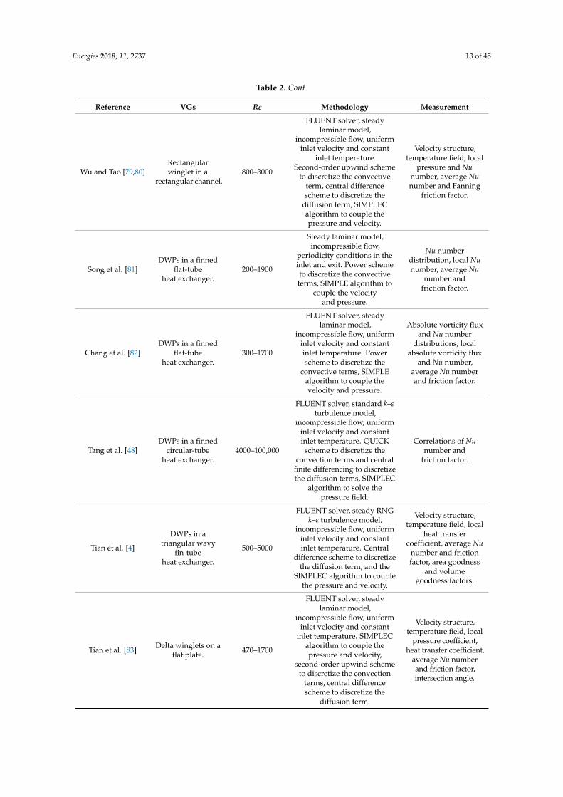
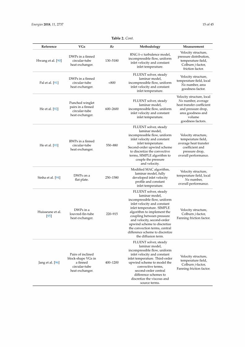
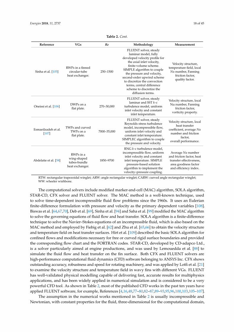
The computational solvers include modified marker-and-cell (MAC) algorithm, SOLA algorithm,STAR-CD, CFX solver and FLUENT solver. The MAC method is a well-known technique, usedto solve time-dependent incompressible fluid flow problems since the 1960s. It uses an Eulerianfinite-difference formulation with pressure and velocity as the primary dependent variables [108].Biswas et al. [64,67,70], Deb et al. [69], Sinha et al. [94] and Saha et al. [99] modified the MAC algorithmto solve the governing equations of fluid flow and heat transfer. SOLA algorithm is a finite-differencetechnique to solve the Navier–Stokes equations of an incompressible fluid, which is also based on theMAC method and employed by Fiebig et al. [62] and Zhu et al. [65,66] to obtain the velocity structureand temperature field on heat transfer surfaces. Hirt et al. [109] described the basic SOLA algorithm forconfined flows and modifications necessary for free or curved rigid surface boundaries and providedthe corresponding flow chart and the FORTRAN codes. STAR-CD, developed by CD-adapco Ltd.,is a solver particularly aimed at engine productions, and was used by Lemouedda et al. [88] tosimulate the fluid flow and heat transfer on the fin surface. Both CFX and FLUENT solvers arehigh-performance computational fluid dynamics (CFD) software belonging to ANSYS Inc. CFX showsoutstanding accuracy, robustness and speed for rotating machinery, and was applied by Lotfi et al. [21]to examine the velocity structure and temperature field in wavy fins with different VGs. FLUENThas well-validated physical modelling capable of delivering fast, accurate results for multiphysicsapplications, and has been widely applied in numerical simulation and is considered to be a verypowerful CFD tool. As shown in Table 2, most of the published CFD works in the past ten years haveapplied FLUENT software, for example, References [4,16,48,77–80,82–87,89–93,95,96,100,103,105–107].
The assumption in the numerical works mentioned in Table 2 is usually incompressible andNewtonian, with constant properties for the fluid, three-dimensional for the computational domain,

Energies 2018, 11, 2737 19 of 45
and with negligible buoyance force and viscous dissipation. To the best of the authors’ knowledge,these assumptions are valid for low-pressure flow covering short temperature variation. However,some engineering problems involve high-pressure flow and cover large temperature variation, leadingto deviation from the assumption of incompressible fluid, constant properties and negligible buoyanceforce. In those cases, the temperature-dependent thermophysical properties, or even the real-gas modelof thermodynamic properties, should be employed in the numerical modelling, and the influence of thegravity should be considered. In addition, for highly compressible flows, the temperature distributionnear the heat transfer surface may be significantly different from the bulk flow; in that case, the heatingby viscous dissipation should be taken into account.
From Table 2, it is noted that the standard k–ε model, RNG k–ε model and SST k–ε model areusually applied to investigate the effect of turbulence on the flow field caused by VGs. As pointedout by Cebeci et al. [110], the standard k–ε model is the most widely used and validated model,but does not function well for flows involving significant curvature, swirl, sudden acceleration,separation and low-Re regions. The RNG k–ε model and SST k–ε model modify the standard k–ε
model to improve simulations for swirling flows and flow separation, but the RNG k–ε model is notas stable as the standard k–ε model and the SST k–ε model needs fine mesh close to the wall andalso over-predicts turbulence in regions with large normal strain, e.g., stagnation regions and regionswith strong acceleration. The choice of turbulence model depends on many considerations, e.g., fluidthermophysical properties, calculation accuracy, computational resource, simulation time, capabilityand limitations of various models, etc. For example, if the real-gas thermodynamic properties areconsidered in the numerical modellings, the simulation time will be much longer than those employingan assumption of fluid constant properties.
As indicated in Table 2, the uniform inlet velocity and constant inlet temperature are generallyassumed at the inlet of the computational domain, while a few researchers apply periodical fullydeveloped fluid flow conditions at the inlet and outlet of the flow passage. To simplify the physicalmodel and save the computational time, a geometrical element with periodic or symmetry boundaryconditions is usually applied as the simulation domain. The periodic boundary condition is used forcomputation geometries and flow patterns with a periodically repeating nature, while the symmetryboundary condition is for those having mirror symmetry; both of them can significantly reduce therequired simulation time. However, to the best of the authors’ knowledge, for periodic and symmetryboundary conditions, it is important to verify the obtained solution critically, because it may introduceunphysical correlations.
For applying numerical methods to solve the governing equations, the finite-volume methodhas been successfully applied in simulations using the local conservation principle. As demonstratedin Table 2, the second-order upwind scheme, the power scheme and the third-order QUICK schemeare usually used to discretize the convection terms, the second-order central difference schemeis always applied to discretize the diffusion terms and the SIMPLE or SIMPLEC algorithms aregenerally employed in order to implement the coupling between pressure and velocity. The choice ofdiscretization scheme also relies on many considerations, e.g., ratio of convective term to diffusiveone, accuracy, robustness, etc. The second-order upwind scheme and the QUICK scheme are good forall ratios of convective terms to diffusive ones, while the power scheme is suitable for intermediatevalues. The power scheme and the QUICK scheme can be more accurate than the second-order upwindscheme, but at the expense of numerical stability. The SIMPLE algorithm employs a starting guess ofpressure and velocity to solve the momentum equation, but the starting guess may not be correct, sothat the obtained velocities will not satisfy continuity. SIMPLEC, as a modified form of the SIMPLEalgorithm, usually performs better in situations in which the rate of convergence is limited by thepressure–velocity coupling, such as non-complex laminar flow cases [110].
Energies 2018, 11, 2737 20 of 45
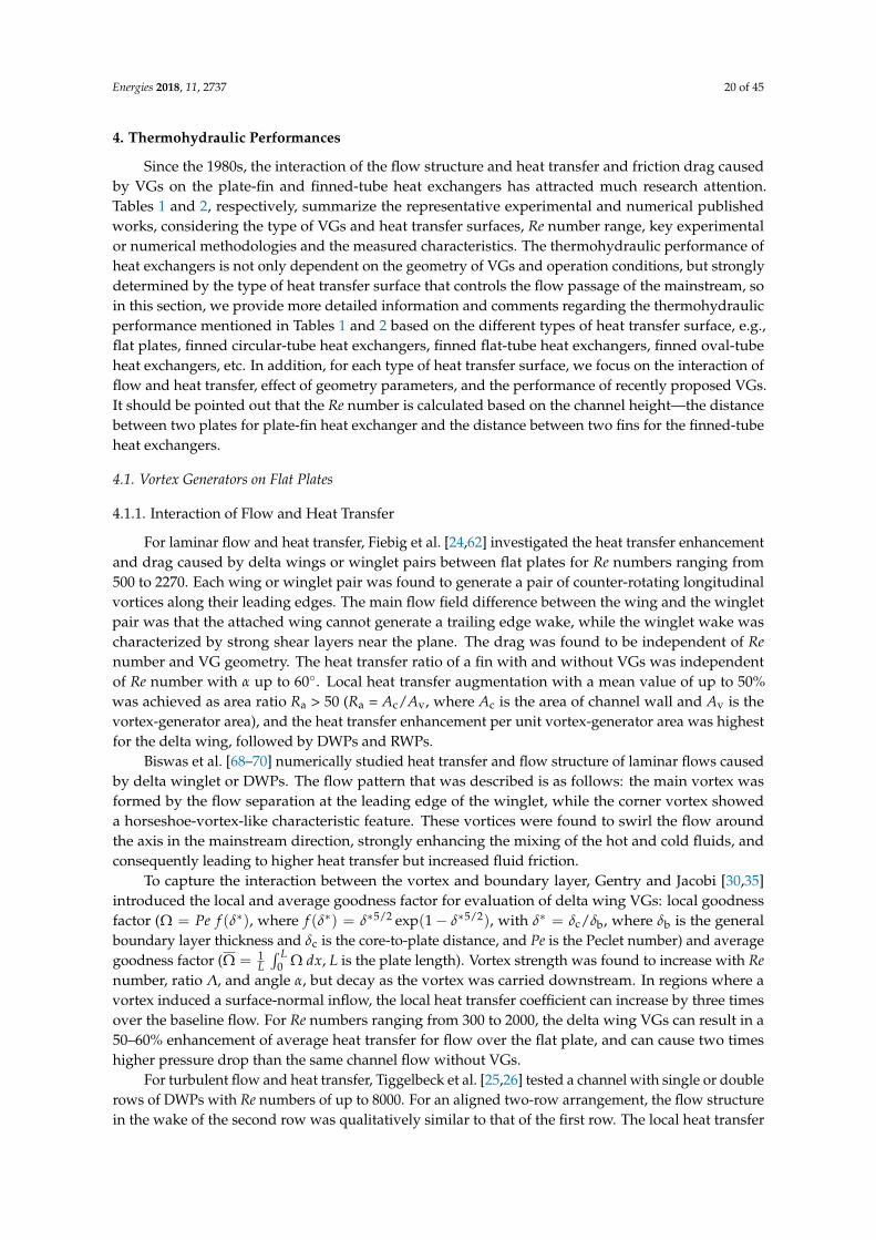
4. Thermohydraulic Performances
Since the 1980s, the interaction of the flow structure and heat transfer and friction drag causedby VGs on the plate-fin and finned-tube heat exchangers has attracted much research attention.Tables 1 and 2, respectively, summarize the representative experimental and numerical publishedworks, considering the type of VGs and heat transfer surfaces, Re number range, key experimentalor numerical methodologies and the measured characteristics. The thermohydraulic performance ofheat exchangers is not only dependent on the geometry of VGs and operation conditions, but stronglydetermined by the type of heat transfer surface that controls the flow passage of the mainstream, soin this section, we provide more detailed information and comments regarding the thermohydraulicperformance mentioned in Tables 1 and 2 based on the different types of heat transfer surface, e.g.,flat plates, finned circular-tube heat exchangers, finned flat-tube heat exchangers, finned oval-tubeheat exchangers, etc. In addition, for each type of heat transfer surface, we focus on the interaction offlow and heat transfer, effect of geometry parameters, and the performance of recently proposed VGs.It should be pointed out that the Re number is calculated based on the channel height—the distancebetween two plates for plate-fin heat exchanger and the distance between two fins for the finned-tubeheat exchangers.
4.1. Vortex Generators on Flat Plates
4.1.1. Interaction of Flow and Heat Transfer
For laminar flow and heat transfer, Fiebig et al. [24,62] investigated the heat transfer enhancementand drag caused by delta wings or winglet pairs between flat plates for Re numbers ranging from500 to 2270. Each wing or winglet pair was found to generate a pair of counter-rotating longitudinalvortices along their leading edges. The main flow field difference between the wing and the wingletpair was that the attached wing cannot generate a trailing edge wake, while the winglet wake wascharacterized by strong shear layers near the plane. The drag was found to be independent of Renumber and VG geometry. The heat transfer ratio of a fin with and without VGs was independentof Re number with α up to 60. Local heat transfer augmentation with a mean value of up to 50%was achieved as area ratio Ra > 50 (Ra = Ac/Av, where Ac is the area of channel wall and Av is thevortex-generator area), and the heat transfer enhancement per unit vortex-generator area was highestfor the delta wing, followed by DWPs and RWPs.
Biswas et al. [68–70] numerically studied heat transfer and flow structure of laminar flows causedby delta winglet or DWPs. The flow pattern that was described is as follows: the main vortex wasformed by the flow separation at the leading edge of the winglet, while the corner vortex showeda horseshoe-vortex-like characteristic feature. These vortices were found to swirl the flow aroundthe axis in the mainstream direction, strongly enhancing the mixing of the hot and cold fluids, andconsequently leading to higher heat transfer but increased fluid friction.
To capture the interaction between the vortex and boundary layer, Gentry and Jacobi [30,35]introduced the local and average goodness factor for evaluation of delta wing VGs: local goodnessfactor (Ω = Pe f (δ∗), where f (δ∗) = δ∗5/2 exp(1− δ∗5/2), with δ∗ = δc/δb, where δb is the generalboundary layer thickness and δc is the core-to-plate distance, and Pe is the Peclet number) and averagegoodness factor (Ω = 1
L∫ L
0 Ω dx, L is the plate length). Vortex strength was found to increase with Renumber, ratio Λ, and angle α, but decay as the vortex was carried downstream. In regions where avortex induced a surface-normal inflow, the local heat transfer coefficient can increase by three timesover the baseline flow. For Re numbers ranging from 300 to 2000, the delta wing VGs can result in a50–60% enhancement of average heat transfer for flow over the flat plate, and can cause two timeshigher pressure drop than the same channel flow without VGs.
For turbulent flow and heat transfer, Tiggelbeck et al. [25,26] tested a channel with single or doublerows of DWPs with Re numbers of up to 8000. For an aligned two-row arrangement, the flow structurein the wake of the second row was qualitatively similar to that of the first row. The local heat transfer
Energies 2018, 11, 2737 21 of 45
enhancement, normalized at the wake of the second row, was strongly dependent on the spacing ofthe two rows, and the maximum local heat transfer enhancement was found behind the second-rowwinglets for row spacings of 7–10 channel heights. For a staggered double-row configuration, lowerheat transfer enhancement was found than for the aligned configuration, particularly for angle α nearthe critical value of 70 for the first row and 55 for the second.
Kotcioglu et al. [31] investigated the heat transfer and flow structure for a rectangular channeldeveloped between flat plates containing RWPs for Re numbers between 3000 and 30,000. Study ofdifferent winglet arrangements showed that an increased winglet inclination angle improved the heattransfer by increasing the mixing effect in the intermediate region between wing cascades. Frictionfactor f and average Nu number strongly depended on Re number and an increase in heat transfercoefficient was usually accompanied by a large pressure drop. Average Nu number and factor fcorrelations were derived with the geometry (a: width of the duct; b: height of the duct; c: length ofwinglet in streamwise direction; and β: inclination angle).
Nu = 1.48Re0.63(ab)
0.70(
cL)
0.65(tan β)1.42 (1)
f = C0Re−m (2)
for Pr = 0.71 and 0 < β < 27. The values of C0 and m were different for each channel configuration.For much higher Re numbers (>50,000), Zhu et al. [65,66] found that the longitudinal vortices
produced by the VGs can significantly elevate the level of turbulence kinetic energy in theflows, strongly disturb the thermal boundary layer near the wall, and thus result in clear heattransfer augmentation.
4.1.2. Effect of Geometry Parameters
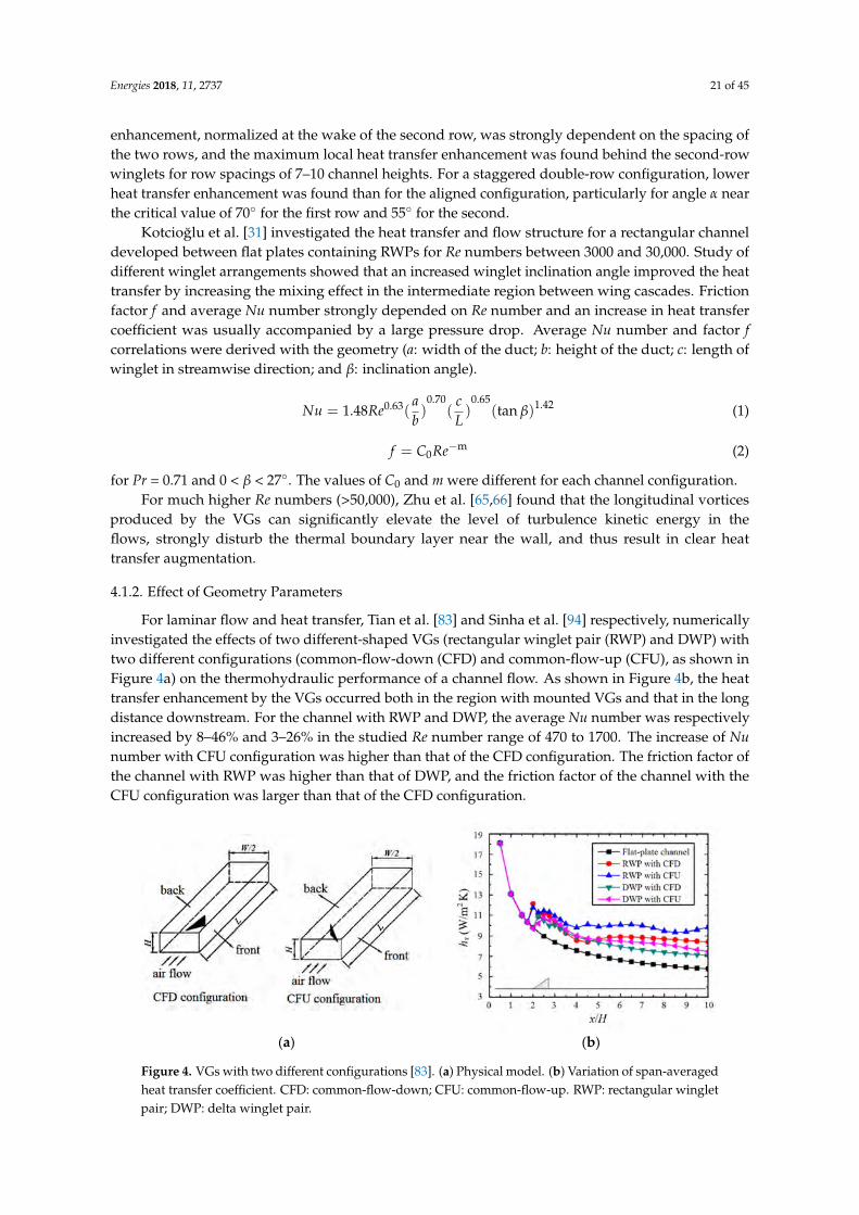
For laminar flow and heat transfer, Tian et al. [83] and Sinha et al. [94] respectively, numericallyinvestigated the effects of two different-shaped VGs (rectangular winglet pair (RWP) and DWP) withtwo different configurations (common-flow-down (CFD) and common-flow-up (CFU), as shown inFigure 4a) on the thermohydraulic performance of a channel flow. As shown in Figure 4b, the heattransfer enhancement by the VGs occurred both in the region with mounted VGs and that in the longdistance downstream. For the channel with RWP and DWP, the average Nu number was respectivelyincreased by 8–46% and 3–26% in the studied Re number range of 470 to 1700. The increase of Nunumber with CFU configuration was higher than that of the CFD configuration. The friction factor ofthe channel with RWP was higher than that of DWP, and the friction factor of the channel with theCFU configuration was larger than that of the CFD configuration.
Energies 2018, 11, x FOR PEER REVIEW 18 of 41
coefficient was usually accompanied by a large pressure drop. Average Nu number and factor f correlations were derived with the geometry (a: width of the duct; b: height of the duct; c: length of winglet in streamwise direction; and β: inclination angle).
0.63 0.70 0.65 1.421.48 ( ) ( ) (tan )a c
Nu Reb L
β= (1)
m0f C Re−= (2)
for Pr = 0.71 and 0 < β < 27°. The values of C0 and m were different for each channel configuration. For much higher Re numbers (>50,000), Zhu et al. [65,66] found that the longitudinal vortices
produced by the VGs can significantly elevate the level of turbulence kinetic energy in the flows, strongly disturb the thermal boundary layer near the wall, and thus result in clear heat transfer augmentation.
4.1.2. Effect of Geometry Parameters
For laminar flow and heat transfer, Tian et al. [83] and Sinha et al. [94] respectively, numerically investigated the effects of two different-shaped VGs (rectangular winglet pair (RWP) and DWP) with two different configurations (common-flow-down (CFD) and common-flow-up (CFU), as shown in Figure 4a) on the thermohydraulic performance of a channel flow. As shown in Figure 4b, the heat transfer enhancement by the VGs occurred both in the region with mounted VGs and that in the long distance downstream. For the channel with RWP and DWP, the average Nu number was respectively increased by 8–46% and 3–26% in the studied Re number range of 470 to 1700. The increase of Nu number with CFU configuration was higher than that of the CFD configuration. The friction factor of the channel with RWP was higher than that of DWP, and the friction factor of the channel with the CFU configuration was larger than that of the CFD configuration.
(a) (b)
Figure 4. VGs with two different configurations [83]. (a) Physical model. (b) Variation of span-averaged heat transfer coefficient. CFD: common-flow-down; CFU: common-flow-up. RWP: rectangular winglet pair; DWP: delta winglet pair.
Sinha et al. [94] investigated the effects of different orientations of winglet arrays on the thermohydraulic performance for Re numbers ranging from 250 to 1580. Five different strategic placements were considered, including common-flow-up in series, common-flow-down in series, combined, inline rows of winglet, and staggered rows of winglet. These placements were respectively abbreviated as CFU-CFU, CFD-CFD, CFD-CFU, IRW and SRW. Among the different types of arrangements of VGs, the CFD-CFU configuration was found to perform best in terms of heat
transfer, as well as quality factor ( f
jQ
f= , where j is the Colburn factor
1 / 3
Nuj
Re Pr= ).
Wu and Tao [55] studied the effects of four different angle α: 15°, 30°, 45° and 60° for DWP on the heat transfer of channel flows for Re numbers in a range of 500–2000. The average Nu number was found to increase with increased α compared with that of a plain plate without DWP.
Figure 4. VGs with two different configurations [83]. (a) Physical model. (b) Variation of span-averagedheat transfer coefficient. CFD: common-flow-down; CFU: common-flow-up. RWP: rectangular wingletpair; DWP: delta winglet pair.
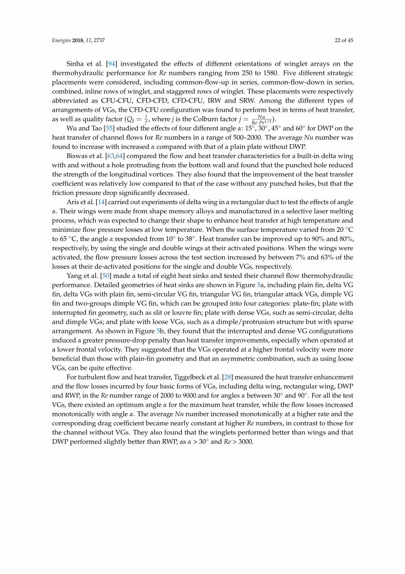
Energies 2018, 11, 2737 22 of 45
Sinha et al. [94] investigated the effects of different orientations of winglet arrays on thethermohydraulic performance for Re numbers ranging from 250 to 1580. Five different strategicplacements were considered, including common-flow-up in series, common-flow-down in series,combined, inline rows of winglet, and staggered rows of winglet. These placements were respectivelyabbreviated as CFU-CFU, CFD-CFD, CFD-CFU, IRW and SRW. Among the different types ofarrangements of VGs, the CFD-CFU configuration was found to perform best in terms of heat transfer,as well as quality factor (Qf =
jf , where j is the Colburn factor j = Nu
Re Pr1/3 ).Wu and Tao [55] studied the effects of four different angle α: 15, 30, 45 and 60 for DWP on the
heat transfer of channel flows for Re numbers in a range of 500–2000. The average Nu number wasfound to increase with increased α compared with that of a plain plate without DWP.
Biswas et al. [63,64] compared the flow and heat transfer characteristics for a built-in delta wingwith and without a hole protruding from the bottom wall and found that the punched hole reducedthe strength of the longitudinal vortices. They also found that the improvement of the heat transfercoefficient was relatively low compared to that of the case without any punched holes, but that thefriction pressure drop significantly decreased.
Aris et al. [14] carried out experiments of delta wing in a rectangular duct to test the effects of angleα. Their wings were made from shape memory alloys and manufactured in a selective laser meltingprocess, which was expected to change their shape to enhance heat transfer at high temperature andminimize flow pressure losses at low temperature. When the surface temperature varied from 20 Cto 65 C, the angle α responded from 10 to 38. Heat transfer can be improved up to 90% and 80%,respectively, by using the single and double wings at their activated positions. When the wings wereactivated, the flow pressure losses across the test section increased by between 7% and 63% of thelosses at their de-activated positions for the single and double VGs, respectively.
Yang et al. [50] made a total of eight heat sinks and tested their channel flow thermohydraulicperformance. Detailed geometries of heat sinks are shown in Figure 5a, including plain fin, delta VGfin, delta VGs with plain fin, semi-circular VG fin, triangular VG fin, triangular attack VGs, dimple VGfin and two-groups dimple VG fin, which can be grouped into four categories: plate-fin; plate withinterrupted fin geometry, such as slit or louvre fin; plate with dense VGs, such as semi-circular, deltaand dimple VGs; and plate with loose VGs, such as a dimple/protrusion structure but with sparsearrangement. As shown in Figure 5b, they found that the interrupted and dense VG configurationsinduced a greater pressure-drop penalty than heat transfer improvements, especially when operated ata lower frontal velocity. They suggested that the VGs operated at a higher frontal velocity were morebeneficial than those with plain-fin geometry and that an asymmetric combination, such as using looseVGs, can be quite effective.
For turbulent flow and heat transfer, Tiggelbeck et al. [28] measured the heat transfer enhancementand the flow losses incurred by four basic forms of VGs, including delta wing, rectangular wing, DWPand RWP, in the Re number range of 2000 to 9000 and for angles α between 30 and 90. For all the testVGs, there existed an optimum angle α for the maximum heat transfer, while the flow losses increasedmonotonically with angle α. The average Nu number increased monotonically at a higher rate and thecorresponding drag coefficient became nearly constant at higher Re numbers, in contrast to those forthe channel without VGs. They also found that the winglets performed better than wings and thatDWP performed slightly better than RWP, as α > 30 and Re > 3000.

Energies 2018, 11, 2737 23 of 45
Energies 2018, 11, x FOR PEER REVIEW 19 of 41
Biswas et al. [63,64] compared the flow and heat transfer characteristics for a built-in delta wing with and without a hole protruding from the bottom wall and found that the punched hole reduced the strength of the longitudinal vortices. They also found that the improvement of the heat transfer coefficient was relatively low compared to that of the case without any punched holes, but that the friction pressure drop significantly decreased.
Aris et al. [14] carried out experiments of delta wing in a rectangular duct to test the effects of angle α. Their wings were made from shape memory alloys and manufactured in a selective laser melting process, which was expected to change their shape to enhance heat transfer at high temperature and minimize flow pressure losses at low temperature. When the surface temperature varied from 20 °C to 65 °C, the angle α responded from 10° to 38°. Heat transfer can be improved up to 90% and 80%, respectively, by using the single and double wings at their activated positions. When the wings were activated, the flow pressure losses across the test section increased by between 7% and 63% of the losses at their de-activated positions for the single and double VGs, respectively.
Yang et al. [50] made a total of eight heat sinks and tested their channel flow thermohydraulic performance. Detailed geometries of heat sinks are shown in Figure 5a, including plain fin, delta VG fin, delta VGs with plain fin, semi-circular VG fin, triangular VG fin, triangular attack VGs, dimple VG fin and two-groups dimple VG fin, which can be grouped into four categories: plate-fin; plate with interrupted fin geometry, such as slit or louvre fin; plate with dense VGs, such as semi-circular, delta and dimple VGs; and plate with loose VGs, such as a dimple/protrusion structure but with sparse arrangement. As shown in Figure 5b, they found that the interrupted and dense VG configurations induced a greater pressure-drop penalty than heat transfer improvements, especially when operated at a lower frontal velocity. They suggested that the VGs operated at a higher frontal velocity were more beneficial than those with plain-fin geometry and that an asymmetric combination, such as using loose VGs, can be quite effective.
(a) (b)
Figure 5. VGs with different configurations [50]. (a) Physical model and relevant geometrical parameters. (b) Pressure drop and heat transfer coefficients.
For turbulent flow and heat transfer, Tiggelbeck et al. [28] measured the heat transfer enhancement and the flow losses incurred by four basic forms of VGs, including delta wing, rectangular wing, DWP and RWP, in the Re number range of 2000 to 9000 and for angles α between 30° and 90°. For all the test VGs, there existed an optimum angle α for the maximum heat transfer, while the flow losses increased monotonically with angle α. The average Nu number increased monotonically at a higher rate and the corresponding drag coefficient became nearly constant at higher Re numbers, in contrast to those for the channel without VGs. They also found that the winglets performed better than wings and that DWP performed slightly better than RWP, as α > 30° and Re > 3000.
Figure 5. VGs with different configurations [50]. (a) Physical model and relevant geometricalparameters. (b) Pressure drop and heat transfer coefficients.
4.1.3. Performance of Recently Proposed Vortex Generators
Min et al. [53] tested the thermohydraulic performances of three modified RWPs, obtained bycutting off the four corners of a rectangular wing with Re number ranging from 5000 to 17,500. Resultsshow that all the modified RWPs were found to have better thermohydraulic performance than thereference RWPs, and that the average Nu number of the modified ones generally increased with angleα in the range of 0 to 55 and showed slightly lower values with α > 55.
Zhou and Ye [18] experimentally investigated the thermohydraulic performance of curvedtrapezoidal winglet pairs (CTWPs) (as shown in Figure 2c) in the Re number range between 700and 26,800 and compared those with traditional RWPs, DWPs and TWPs. Comparison of threedimensionless factors (j/j0, f /f 0 and (j/j0)/(f /f 0)) showed that the DWPs were the best in the laminarand transitional flow regions, while CTWPs had the best performance in the fully turbulent region asa result of both the streamlined configuration and the decreased pressure drop. A parametric studyon CTWPs showed that smaller angle α, larger curvature and larger angle of inclination gave betterperformance under the tested conditions.
Zhou and Feng [19] examined the performance of plane and curved winglet (rectangular,trapezoidal and delta) VGs with and without punched holes for Re numbers ranging from 650 to21,000. The curved winglet-type VGs were found to again have better heat transfer enhancement andlower flow resistance than the corresponding plane winglet VGs in both laminar and turbulent flowregions. The curved DWPs presented the best performance, followed by the CTWPs, when consideringall flow regions. The punched holes really improved the performance of the VGs and decreased theflow resistance for all cases, but the optimal diameter of the holes needed to be matched with the VGface area.
Esmaeilzadeh et al. [107] numerically investigated the thermal and fluid flow characteristics ofTWPs and CTWPs in a flat channel with Re numbers in the range 7000–35,000. The flow structureconsisted of a corner (horseshoe) vortex, an induced vortex and the main vortex, which causedsignificant heat transfer effects in the downstream region, as shown in Figure 6. According to theperformance evaluation parameter ((Nu/Nu0)/(f /f 0)), the channel with CTWPs had a better overallperformance, whereby the mean Nu number was augmented by 6–8% and 9–12% and the globalfriction factor increased by 24–29% and 38–48% with CTWPs and TWPs, respectively, compared with asmooth channel.
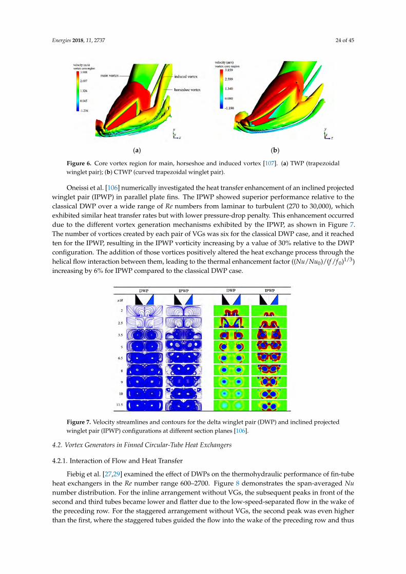
Energies 2018, 11, 2737 24 of 45
Energies 2018, 11, x FOR PEER REVIEW 20 of 41
4.1.3. Performance of Recently Proposed Vortex Generators
Min et al. [53] tested the thermohydraulic performances of three modified RWPs, obtained by cutting off the four corners of a rectangular wing with Re number ranging from 5000 to 17,500. Results show that all the modified RWPs were found to have better thermohydraulic performance than the reference RWPs, and that the average Nu number of the modified ones generally increased with angle α in the range of 0° to 55° and showed slightly lower values with α > 55°.
Zhou and Ye [18] experimentally investigated the thermohydraulic performance of curved trapezoidal winglet pairs (CTWPs) (as shown in Figure 2c) in the Re number range between 700 and 26,800 and compared those with traditional RWPs, DWPs and TWPs. Comparison of three dimensionless factors (j/j0, f/f0 and (j/j0)/(f/f0)) showed that the DWPs were the best in the laminar and transitional flow regions, while CTWPs had the best performance in the fully turbulent region as a result of both the streamlined configuration and the decreased pressure drop. A parametric study on CTWPs showed that smaller angle α, larger curvature and larger angle of inclination gave better performance under the tested conditions.
Zhou and Feng [19] examined the performance of plane and curved winglet (rectangular, trapezoidal and delta) VGs with and without punched holes for Re numbers ranging from 650 to 21,000. The curved winglet-type VGs were found to again have better heat transfer enhancement and lower flow resistance than the corresponding plane winglet VGs in both laminar and turbulent flow regions. The curved DWPs presented the best performance, followed by the CTWPs, when considering all flow regions. The punched holes really improved the performance of the VGs and decreased the flow resistance for all cases, but the optimal diameter of the holes needed to be matched with the VG face area.
Esmaeilzadeh et al. [107] numerically investigated the thermal and fluid flow characteristics of TWPs and CTWPs in a flat channel with Re numbers in the range 7000–35,000. The flow structure consisted of a corner (horseshoe) vortex, an induced vortex and the main vortex, which caused significant heat transfer effects in the downstream region, as shown in Figure 6. According to the performance evaluation parameter ((Nu/Nu0)/(f/f0)), the channel with CTWPs had a better overall performance, whereby the mean Nu number was augmented by 6–8% and 9–12% and the global friction factor increased by 24–29% and 38–48% with CTWPs and TWPs, respectively, compared with a smooth channel.
(a) (b)
Figure 6. Core vortex region for main, horseshoe and induced vortex [107]. (a) TWP (trapezoidal winglet pair); (b) CTWP (curved trapezoidal winglet pair).
Oneissi et al. [106] numerically investigated the heat transfer enhancement of an inclined projected winglet pair (IPWP) in parallel plate fins. The IPWP showed superior performance relative to the classical DWP over a wide range of Re numbers from laminar to turbulent (270 to 30,000), which exhibited similar heat transfer rates but with lower pressure-drop penalty. This enhancement occurred due to the different vortex generation mechanisms exhibited by the IPWP, as shown in Figure 7. The number of vortices created by each pair of VGs was six for the classical DWP case, and it reached ten for the IPWP, resulting in the IPWP vorticity increasing by a value of 30% relative to
Figure 6. Core vortex region for main, horseshoe and induced vortex [107]. (a) TWP (trapezoidalwinglet pair); (b) CTWP (curved trapezoidal winglet pair).
Oneissi et al. [106] numerically investigated the heat transfer enhancement of an inclined projectedwinglet pair (IPWP) in parallel plate fins. The IPWP showed superior performance relative to theclassical DWP over a wide range of Re numbers from laminar to turbulent (270 to 30,000), whichexhibited similar heat transfer rates but with lower pressure-drop penalty. This enhancement occurreddue to the different vortex generation mechanisms exhibited by the IPWP, as shown in Figure 7.The number of vortices created by each pair of VGs was six for the classical DWP case, and it reachedten for the IPWP, resulting in the IPWP vorticity increasing by a value of 30% relative to the DWPconfiguration. The addition of those vortices positively altered the heat exchange process through thehelical flow interaction between them, leading to the thermal enhancement factor ((Nu/Nu0)/(f /f 0)1/3)increasing by 6% for IPWP compared to the classical DWP case.
Energies 2018, 11, x FOR PEER REVIEW 21 of 41
the DWP configuration. The addition of those vortices positively altered the heat exchange process through the helical flow interaction between them, leading to the thermal enhancement factor ((Nu/Nu0)/(f/f0)1/3) increasing by 6% for IPWP compared to the classical DWP case.
Figure 7. Velocity streamlines and contours for the delta winglet pair (DWP) and inclined projected winglet pair (IPWP) configurations at different section planes [106].
4.2. Vortex Generators in Finned Circular-Tube Heat Exchangers
4.2.1. Interaction of Flow and Heat Transfer
Fiebig et al. [27,29] examined the effect of DWPs on the thermohydraulic performance of fin-tube heat exchangers in the Re number range 600–2700. Figure 8 demonstrates the span-averaged Nu number distribution. For the inline arrangement without VGs, the subsequent peaks in front of the second and third tubes became lower and flatter due to the low-speed-separated flow in the wake of the preceding row. For the staggered arrangement without VGs, the second peak was even higher than the first, where the staggered tubes guided the flow into the wake of the preceding row and thus reduced the wake. In addition, the increased velocity in front of the second tube caused a stronger horseshoe vortex and a higher heat transfer peak. The third peak caused by the horseshoe vortex region was lower than that of the second row because the third tube row lay in the wake of the first row.
Figure 8. Span-averaged Nu number for various configurations [27].
Biswas et al. [67,76] numerically investigated the flow structure and heat transfer enhancement with DWPs for Re numbers ranging from 500 to 1000. In the absence of VGs, the recirculation region,
Figure 7. Velocity streamlines and contours for the delta winglet pair (DWP) and inclined projectedwinglet pair (IPWP) configurations at different section planes [106].
4.2. Vortex Generators in Finned Circular-Tube Heat Exchangers
4.2.1. Interaction of Flow and Heat Transfer
Fiebig et al. [27,29] examined the effect of DWPs on the thermohydraulic performance of fin-tubeheat exchangers in the Re number range 600–2700. Figure 8 demonstrates the span-averaged Nunumber distribution. For the inline arrangement without VGs, the subsequent peaks in front of thesecond and third tubes became lower and flatter due to the low-speed-separated flow in the wake ofthe preceding row. For the staggered arrangement without VGs, the second peak was even higherthan the first, where the staggered tubes guided the flow into the wake of the preceding row and thus

Energies 2018, 11, 2737 25 of 45
reduced the wake. In addition, the increased velocity in front of the second tube caused a strongerhorseshoe vortex and a higher heat transfer peak. The third peak caused by the horseshoe vortexregion was lower than that of the second row because the third tube row lay in the wake of the first row.
Energies 2018, 11, x FOR PEER REVIEW 21 of 41
the DWP configuration. The addition of those vortices positively altered the heat exchange process through the helical flow interaction between them, leading to the thermal enhancement factor ((Nu/Nu0)/(f/f0)1/3) increasing by 6% for IPWP compared to the classical DWP case.
Figure 7. Velocity streamlines and contours for the delta winglet pair (DWP) and inclined projected winglet pair (IPWP) configurations at different section planes [106].
4.2. Vortex Generators in Finned Circular-Tube Heat Exchangers
4.2.1. Interaction of Flow and Heat Transfer
Fiebig et al. [27,29] examined the effect of DWPs on the thermohydraulic performance of fin-tube heat exchangers in the Re number range 600–2700. Figure 8 demonstrates the span-averaged Nu number distribution. For the inline arrangement without VGs, the subsequent peaks in front of the second and third tubes became lower and flatter due to the low-speed-separated flow in the wake of the preceding row. For the staggered arrangement without VGs, the second peak was even higher than the first, where the staggered tubes guided the flow into the wake of the preceding row and thus reduced the wake. In addition, the increased velocity in front of the second tube caused a stronger horseshoe vortex and a higher heat transfer peak. The third peak caused by the horseshoe vortex region was lower than that of the second row because the third tube row lay in the wake of the first row.
Figure 8. Span-averaged Nu number for various configurations [27].
Biswas et al. [67,76] numerically investigated the flow structure and heat transfer enhancement with DWPs for Re numbers ranging from 500 to 1000. In the absence of VGs, the recirculation region,
Figure 8. Span-averaged Nu number for various configurations [27].
Biswas et al. [67,76] numerically investigated the flow structure and heat transfer enhancementwith DWPs for Re numbers ranging from 500 to 1000. In the absence of VGs, the recirculationregion, with low velocity fluid in the downstream of the circular tube, resulted in relatively littleheat transfer, while the presence of the DWPs in the wake region significantly enhanced heat transferthere. They attributed the enhancement to the nozzle-like flow passages and the strong swirlingmotion originating from the streamwise longitudinal vortices behind the DWPs. The nozzle-like flowpassages promoted acceleration and thereby removed the zone of poor heat transfer from the nearwake. The swirling motion caused intermixing of the fluid layers to disrupt the growth of the thermalboundary layer.
Joardar and Jacobi [77] explored the flow and heat transfer with three different wingletconfigurations in a CFU arrangement in a seven-row compact fin-tube heat exchanger, as shownin Figure 9a, including a single VG pair, a 3VG-inline array and a 3VG-staggered array, for Renumbers ranging from 330 to 850. The heat transfer from the leading tube was significantly higherthan for the other tubes due to the horseshoe vortex system. As shown in Figure 9b, due to theflow confinement effects of the inline tube pattern, the winglet-generated vortices were periodicallysubjected to accelerated and decelerated flow, leading to an important heat transfer augmentationmechanism. These local effects caused vortex straining and increased or decreased vortex strength,depending on whether the vortex was stretched or compressed. A constricted, nozzle-like passagebetween the winglet and tube surface was also found and the flow accelerated in this region to suppressthe wake and delay separation. At Re = 850 with a constant tube-wall temperature, the 3VG-inline-arrayconfiguration achieved enhancements of up to 32% in total heat flux and 74% in Colburn j-factorover the baseline case, with an associated pressure-drop increase of about 41%. Pal et al. [91] andSinha et al. [105] also emphasized the effects of the strong swirling motion behind DWPs or RWPs onheat transfer.
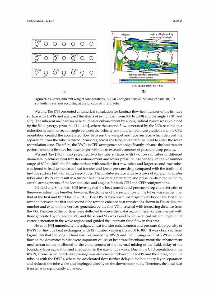
Energies 2018, 11, 2737 26 of 45
Energies 2018, 11, x FOR PEER REVIEW 22 of 41
with low velocity fluid in the downstream of the circular tube, resulted in relatively little heat transfer, while the presence of the DWPs in the wake region significantly enhanced heat transfer there. They attributed the enhancement to the nozzle-like flow passages and the strong swirling motion originating from the streamwise longitudinal vortices behind the DWPs. The nozzle-like flow passages promoted acceleration and thereby removed the zone of poor heat transfer from the near wake. The swirling motion caused intermixing of the fluid layers to disrupt the growth of the thermal boundary layer.
Joardar and Jacobi [77] explored the flow and heat transfer with three different winglet configurations in a CFU arrangement in a seven-row compact fin-tube heat exchanger, as shown in Figure 9a, including a single VG pair, a 3VG-inline array and a 3VG-staggered array, for Re numbers ranging from 330 to 850. The heat transfer from the leading tube was significantly higher than for the other tubes due to the horseshoe vortex system. As shown in Figure 9b, due to the flow confinement effects of the inline tube pattern, the winglet-generated vortices were periodically subjected to accelerated and decelerated flow, leading to an important heat transfer augmentation mechanism. These local effects caused vortex straining and increased or decreased vortex strength, depending on whether the vortex was stretched or compressed. A constricted, nozzle-like passage between the winglet and tube surface was also found and the flow accelerated in this region to suppress the wake and delay separation. At Re = 850 with a constant tube-wall temperature, the 3VG-inline-array configuration achieved enhancements of up to 32% in total heat flux and 74% in Colburn j-factor over the baseline case, with an associated pressure-drop increase of about 41%. Pal et al. [91] and Sinha et al. [105] also emphasized the effects of the strong swirling motion behind DWPs or RWPs on heat transfer.
(a) (b)
Figure 9. VGs with different winglet configurations [77]. (a) Configurations of the winglet pairs. (b) 3D iso-vorticity surfaces occurring at the junction of fin and tube.
Wu and Tao [78] presented a numerical simulation for laminar flow heat transfer of the fin-tube surface with DWPs and analyzed the effects of Re number (from 800 to 2000) and the angle α (30° and 45°). The inherent mechanism of heat transfer enhancement by a longitudinal vortex was explained by the field synergy principle [111–114], where the second flow generated by the VGs resulted in a reduction in the intersection angle between the velocity and fluid temperature gradient and the CFU orientation created the accelerated flow between the winglet and tube surface, which delayed the separation from the tube, reduced form-drag across the tube, and aided the fluid to enter the wake recirculation zone. Therefore, the DWPs in CFU arrangement can significantly enhance the heat transfer performance of a fin-tube heat exchanger without an excessive amount of pressure-drop penalty.
Wu and Tao [56,89] also presented two fin-tube surfaces with two rows of tubes of different diameters to achieve heat transfer enhancement and lower pressure loss penalty. In the Re number range of 800 to 2000, the fin-tube surface with smaller first-row tubes and larger second-row tubes
Figure 9. VGs with different winglet configurations [77]. (a) Configurations of the winglet pairs. (b) 3Diso-vorticity surfaces occurring at the junction of fin and tube.
Wu and Tao [78] presented a numerical simulation for laminar flow heat transfer of the fin-tubesurface with DWPs and analyzed the effects of Re number (from 800 to 2000) and the angle α (30 and45). The inherent mechanism of heat transfer enhancement by a longitudinal vortex was explainedby the field synergy principle [111–114], where the second flow generated by the VGs resulted in areduction in the intersection angle between the velocity and fluid temperature gradient and the CFUorientation created the accelerated flow between the winglet and tube surface, which delayed theseparation from the tube, reduced form-drag across the tube, and aided the fluid to enter the wakerecirculation zone. Therefore, the DWPs in CFU arrangement can significantly enhance the heat transferperformance of a fin-tube heat exchanger without an excessive amount of pressure-drop penalty.
Wu and Tao [56,89] also presented two fin-tube surfaces with two rows of tubes of differentdiameters to achieve heat transfer enhancement and lower pressure loss penalty. In the Re numberrange of 800 to 2000, the fin-tube surface with smaller first-row tubes and larger second-row tubeswas found to lead to increased heat transfer and lower pressure drop compared with the traditionalfin-tube surface but with same sized tubes. The fin-tube surface with two rows of different diametertubes and DWPs can result in a further heat transfer augmentation and pressure-drop reduction bycareful arrangements of the location, size and angle α for both CFU and CFD configurations.
Behfard and Sohankar [103] investigated the heat transfer and pressure-drop characteristics ofthree-row inline tube bundles; however, the diameter of the second row of the tubes was smaller thanthat of the first and third for Re = 1000. Two DWPs were installed respectively beside the first tuberow and between the first and second tube rows to enhance heat transfer. As shown in Figure 10a, thenumber and extent of the vortices generated by the first VG increased with increasing distance fromthe VG. The core of the vortices were deflected towards the wake region; these vortices merged withthose generated by the second VG, and the second VG was found to play a crucial role for longitudinalvortex generation in the wake regions and guided the upstream fluid flow in this area.
He et al. [93] numerically investigated heat transfer enhancement and pressure-drop penalty ofRWPs for fin-tube heat exchangers with Re number varying from 550 to 880. It was observed fromFigure 10b that the longitudinal vortices caused by RWPs and the impingement of RWP-directedflow on the downstream tube were important causes of heat transfer enhancement; the enhancementmechanism can be attributed to the enhancement of the thermal mixing of the fluid, delay of theboundary layer separation and a reduction in the size of tube wake. Due to the CFU orientation of theRWPs, a constricted nozzle-like passage was also created between the RWPs and the aft region of thetube, as with the DWPs, where the accelerated flow further delayed the boundary layer separationand reduced the tube wake and impinged directly on the downstream tube. Therefore, the local heattransfer was significantly enhanced.
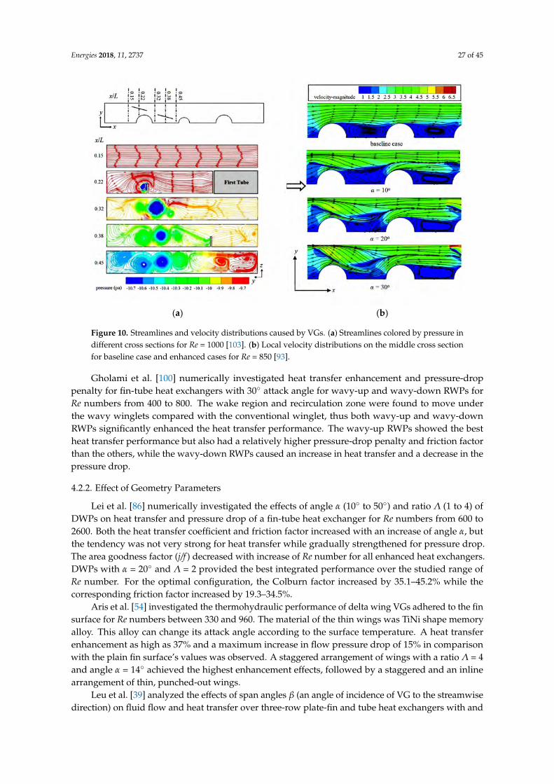
Energies 2018, 11, 2737 27 of 45
Energies 2018, 11, x FOR PEER REVIEW 23 of 41
was found to lead to increased heat transfer and lower pressure drop compared with the traditional fin-tube surface but with same sized tubes. The fin-tube surface with two rows of different diameter tubes and DWPs can result in a further heat transfer augmentation and pressure-drop reduction by careful arrangements of the location, size and angle α for both CFU and CFD configurations.
Behfard and Sohankar [103] investigated the heat transfer and pressure-drop characteristics of three-row inline tube bundles; however, the diameter of the second row of the tubes was smaller than that of the first and third for Re = 1000. Two DWPs were installed respectively beside the first tube row and between the first and second tube rows to enhance heat transfer. As shown in Figure 10a, the number and extent of the vortices generated by the first VG increased with increasing distance from the VG. The core of the vortices were deflected towards the wake region; these vortices merged with those generated by the second VG, and the second VG was found to play a crucial role for longitudinal vortex generation in the wake regions and guided the upstream fluid flow in this area.
(a) (b)
Figure 10. Streamlines and velocity distributions caused by VGs. (a) Streamlines colored by pressure in different cross sections for Re = 1000 [103]. (b) Local velocity distributions on the middle cross section for baseline case and enhanced cases for Re = 850 [93].
He et al. [93] numerically investigated heat transfer enhancement and pressure-drop penalty of RWPs for fin-tube heat exchangers with Re number varying from 550 to 880. It was observed from Figure 10b that the longitudinal vortices caused by RWPs and the impingement of RWP-directed flow on the downstream tube were important causes of heat transfer enhancement; the enhancement mechanism can be attributed to the enhancement of the thermal mixing of the fluid, delay of the boundary layer separation and a reduction in the size of tube wake. Due to the CFU orientation of the RWPs, a constricted nozzle-like passage was also created between the RWPs and the aft region of the tube, as with the DWPs, where the accelerated flow further delayed the boundary layer separation and reduced the tube wake and impinged directly on the downstream tube. Therefore, the local heat transfer was significantly enhanced.
Gholami et al. [100] numerically investigated heat transfer enhancement and pressure-drop penalty for fin-tube heat exchangers with 30° attack angle for wavy-up and wavy-down RWPs for Re numbers from 400 to 800. The wake region and recirculation zone were found to move under the wavy winglets compared with the conventional winglet, thus both wavy-up and wavy-down RWPs significantly enhanced the heat transfer performance. The wavy-up RWPs showed the best heat transfer performance but also had a relatively higher pressure-drop penalty and friction factor than
Figure 10. Streamlines and velocity distributions caused by VGs. (a) Streamlines colored by pressure indifferent cross sections for Re = 1000 [103]. (b) Local velocity distributions on the middle cross sectionfor baseline case and enhanced cases for Re = 850 [93].
Gholami et al. [100] numerically investigated heat transfer enhancement and pressure-droppenalty for fin-tube heat exchangers with 30 attack angle for wavy-up and wavy-down RWPs forRe numbers from 400 to 800. The wake region and recirculation zone were found to move underthe wavy winglets compared with the conventional winglet, thus both wavy-up and wavy-downRWPs significantly enhanced the heat transfer performance. The wavy-up RWPs showed the bestheat transfer performance but also had a relatively higher pressure-drop penalty and friction factorthan the others, while the wavy-down RWPs caused an increase in heat transfer and a decrease in thepressure drop.
4.2.2. Effect of Geometry Parameters
Lei et al. [86] numerically investigated the effects of angle α (10 to 50) and ratio Λ (1 to 4) ofDWPs on heat transfer and pressure drop of a fin-tube heat exchanger for Re numbers from 600 to2600. Both the heat transfer coefficient and friction factor increased with an increase of angle α, butthe tendency was not very strong for heat transfer while gradually strengthened for pressure drop.The area goodness factor (j/f ) decreased with increase of Re number for all enhanced heat exchangers.DWPs with α = 20 and Λ = 2 provided the best integrated performance over the studied range ofRe number. For the optimal configuration, the Colburn factor increased by 35.1–45.2% while thecorresponding friction factor increased by 19.3–34.5%.
Aris et al. [54] investigated the thermohydraulic performance of delta wing VGs adhered to the finsurface for Re numbers between 330 and 960. The material of the thin wings was TiNi shape memoryalloy. This alloy can change its attack angle according to the surface temperature. A heat transferenhancement as high as 37% and a maximum increase in flow pressure drop of 15% in comparisonwith the plain fin surface’s values was observed. A staggered arrangement of wings with a ratio Λ = 4and angle α = 14 achieved the highest enhancement effects, followed by a staggered and an inlinearrangement of thin, punched-out wings.
Leu et al. [39] analyzed the effects of span angles β (an angle of incidence of VG to the streamwisedirection) on fluid flow and heat transfer over three-row plate-fin and tube heat exchangers with and

Energies 2018, 11, 2737 28 of 45
without a pair of inclined block-shape VGs for Re numbers ranging from 400 to 3000. The inclinedblock-shape VGs with β = 45 arrangement was found to provide the best relative heat transferenhancement across the Re range, whereby the Colburn factor increased by 8–30% while the frictionfactor was only increased by 11–15%. The heat transfer enhancement using inclined block VGs wasfound to be more useful for low and moderate Re numbers.
Jang et al. [96] investigated the effects of VG span angle (30 < β < 60) and the VG transverselocation (2 mm < Ly < 20 mm) on the thermohydraulic characteristics of fin-tube heat exchangers withblock type VGs. For both the inline and staggered arrangements, the strength of the longitudinalvortex was intensified and both the j and f factors increased with an increase of both β and Ly.The inline arrangement was found to be more effective for heat transfer enhancement than the
staggered arrangement, with area reduction ratio ( AAref
= ( ffref
)1/2
( jjref
)3/2
) ranges of 14.9–25.5% for theinline arrangement and 7.9–13.6% for the staggered arrangement for 400 < Re < 1200.
Torii et al. [32–34] investigated the heat transfer and pressure-drop penalty for various numbers oftransverse rows in staggered finned-tube bundles for Re numbers ranging from 350 to 2100. As shownin Figure 11a, the DWPs were installed beside a single or two transverse tube row(s). For the one-rowCFU configuration, the three-row staggered tube bundle resulted in heat transfer augmentation of10–30% and a pressure-drop reduction of 34–55%, while for the inline tube bank configuration, thesewere found to be 10–20% augmentation and 8–15% reduction. For the one-row CFD configuration,the three-row staggered tube bundle brought about 5–15% increase in heat transfer enhancement and2–10% increase in pressure-drop penalty, compared with fin-tube bundles without VGs. In addition, forthe two-row CFU configuration, the heat transfer and pressure loss increased by 6–15% and 61–117%in the staggered arrangement, while they increased by 7–9% and 3–9% in an inline arrangement,respectively, compared with the single transverse row case.
Energies 2018, 11, x FOR PEER REVIEW 25 of 41
core( )m
E PA
βρ
= Δ (4)
where Z was the heat transferred by per unit temperature difference and per unit core volume, while E was the fan pumping power consumed by per unit core volume. The 3VG array was found to yield better heat transfer performance compared to the single VG pair but also resulted in a higher pressure-drop penalty. For the single-row winglet arrangement, the airside heat transfer coefficient increased by 16.5% to 44% and the pressure drop increased by less than 12%, while for the 3VG array, the heat transfer coefficient increased by 29.9% to 68.8%, and the pressure drop increased by 26% to 87.5%.
(a) (b)
Figure 11. Geometric arrangements of tube rows and VGs. (a) Geometric arrangements of test core with three tube rows and VGs tested by Torii et al. [32]. (b) Geometric arrangements of test core with tube rows and VGs tested by Joardar and Jacobi et al. [46].
Chu et al. [84] compared the heat transfer characteristics of fin-tube heat exchangers with RWPs for Re numbers ranging from 500 to 880. Three enhanced configurations, including the inline-1RWP case, the inline-3RWP case, and the inline-7RWP case, were mentioned. The airside heat transfer coefficient increased by 28.1–43.9%, 71.3–87.6%, and 98.9–131%, respectively, for the three enhanced configurations. The associated pressure drop increased by 11.3–25.1%, 54.4–72%, and 88.8–121.4%, respectively. The area goodness factor (j/f1/3 versus Re) was used to evaluate the overall performance and the inline-1RWP case showed the best overall performance, followed by the inline-3RWP case and then the inline-7RWP case.
Tian et al. [4] studied the airside heat transfer and fluid flow characteristics of a wavy fin-tube heat exchanger with DWPs for Re numbers varying from 500 to 5000 and analyzed the effects of different geometrical parameters with varying angle α (30°, 45° and 60°), tube row number (2–4), and wavy angle of the fin θ (0–20°). Nu number and factor f both increased with the increase in the angle α, and the case of α = 30° had the maximum value of factor j/f. The effects of the tube row number on Nu number and factor f were very small, and the case of θ = 5° showed the minimum Nu number, while factor f always increased with an increase in wavy angle.
Figure 11. Geometric arrangements of tube rows and VGs. (a) Geometric arrangements of test corewith three tube rows and VGs tested by Torii et al. [32]. (b) Geometric arrangements of test core withtube rows and VGs tested by Joardar and Jacobi et al. [46].

Energies 2018, 11, 2737 29 of 45
Sommers and Jacobi et al. [41] and Joardar and Jacobi et al. [46] examined the effectiveness ofa 3VG alternate-tube inline array for airside heat transfer enhancement (as shown in Figure 11b).The DWPs were placed in a CFU orientation and were conducted over Re number range of 220 to 960.Volume goodness factors were proposed to evaluate the heat transfer and pressure drop performance,and were defined as:
Z = η0hβ (3)
E = ∆Pcore(mAρ
)β (4)
where Z was the heat transferred by per unit temperature difference and per unit core volume, whileE was the fan pumping power consumed by per unit core volume. The 3VG array was found toyield better heat transfer performance compared to the single VG pair but also resulted in a higherpressure-drop penalty. For the single-row winglet arrangement, the airside heat transfer coefficientincreased by 16.5% to 44% and the pressure drop increased by less than 12%, while for the 3VG array,the heat transfer coefficient increased by 29.9% to 68.8%, and the pressure drop increased by 26%to 87.5%.
Chu et al. [84] compared the heat transfer characteristics of fin-tube heat exchangers with RWPsfor Re numbers ranging from 500 to 880. Three enhanced configurations, including the inline-1RWPcase, the inline-3RWP case, and the inline-7RWP case, were mentioned. The airside heat transfercoefficient increased by 28.1–43.9%, 71.3–87.6%, and 98.9–131%, respectively, for the three enhancedconfigurations. The associated pressure drop increased by 11.3–25.1%, 54.4–72%, and 88.8–121.4%,respectively. The area goodness factor (j/f 1/3 versus Re) was used to evaluate the overall performanceand the inline-1RWP case showed the best overall performance, followed by the inline-3RWP case andthen the inline-7RWP case.
Tian et al. [4] studied the airside heat transfer and fluid flow characteristics of a wavy fin-tube heatexchanger with DWPs for Re numbers varying from 500 to 5000 and analyzed the effects of differentgeometrical parameters with varying angle α (30, 45 and 60), tube row number (2–4), and wavyangle of the fin θ (0–20). Nu number and factor f both increased with the increase in the angle α, andthe case of α = 30 had the maximum value of factor j/f. The effects of the tube row number on Nunumber and factor f were very small, and the case of θ = 5 showed the minimum Nu number, whilefactor f always increased with an increase in wavy angle.
Tang et al. [47,48] investigated the airside heat transfer and fluid friction of nine fin-tube heatexchangers. They investigated three numbers of tube rows (6, 9, and 12) and three types of finconfigurations (plain fin, slit fin and fin with DWPs). For Re numbers of 4000 to 10,000, the slit finwas found to provide better overall performance than that with a vortex-generator fin, especially athigh Re numbers, and resulted in both higher heat transfer and pressure drop than the other two finswhen the tube number was larger than six. Then, five kinds of fin-and-tube heat exchangers, includingcrimped spiral fin, plain fin, slit fin, fin with DWPs and mixed fin with front six-row vortex-generatorfin and rear six-row slit fin (as shown in Figure 12) were studied. It was found that a crimped spiral finprovided greater heat transfer and pressure drop than the other four fins, and that the heat exchangerwith the mixed fin had better overall performance than the fin with DWPs and that the slit fin offeredbest heat transfer performance at high Re numbers.
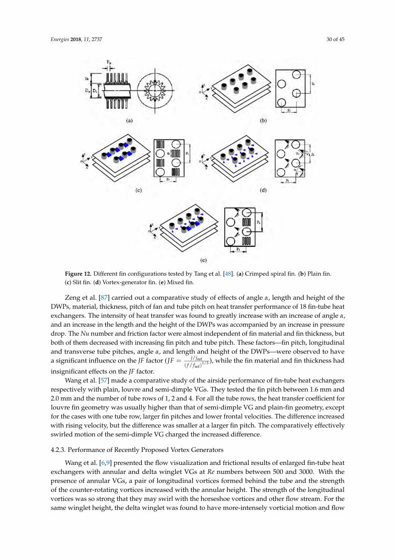
Energies 2018, 11, 2737 30 of 45
Energies 2018, 11, x FOR PEER REVIEW 26 of 41
Tang et al. [47,48] investigated the airside heat transfer and fluid friction of nine fin-tube heat exchangers. They investigated three numbers of tube rows (6, 9, and 12) and three types of fin configurations (plain fin, slit fin and fin with DWPs). For Re numbers of 4000 to 10,000, the slit fin was found to provide better overall performance than that with a vortex-generator fin, especially at high Re numbers, and resulted in both higher heat transfer and pressure drop than the other two fins when the tube number was larger than six. Then, five kinds of fin-and-tube heat exchangers, including crimped spiral fin, plain fin, slit fin, fin with DWPs and mixed fin with front six-row vortex-generator fin and rear six-row slit fin (as shown in Figure 12) were studied. It was found that a crimped spiral fin provided greater heat transfer and pressure drop than the other four fins, and that the heat exchanger with the mixed fin had better overall performance than the fin with DWPs and that the slit fin offered best heat transfer performance at high Re numbers.
Figure 12. Different fin configurations tested by Tang et al. [48]. (a) Crimped spiral fin. (b) Plain fin. (c) Slit fin. (d) Vortex-generator fin. (e) Mixed fin.
Zeng et al. [87] carried out a comparative study of effects of angle α, length and height of the DWPs, material, thickness, pitch of fan and tube pitch on heat transfer performance of 18 fin-tube heat exchangers. The intensity of heat transfer was found to greatly increase with an increase of angle α, and an increase in the length and the height of the DWPs was accompanied by an increase in pressure drop. The Nu number and friction factor were almost independent of fin material and fin thickness, but both of them decreased with increasing fin pitch and tube pitch. These factors—fin pitch, longitudinal and transverse tube pitches, angle α, and length and height of the DWPs—were
observed to have a significant influence on the JF factor ( ref1/ 3
ref
/
( / )
j jJF
f f= ), while the fin material and
fin thickness had insignificant effects on the JF factor. Wang et al. [57] made a comparative study of the airside performance of fin-tube heat
exchangers respectively with plain, louvre and semi-dimple VGs. They tested the fin pitch between 1.6 mm and 2.0 mm and the number of tube rows of 1, 2 and 4. For all the tube rows, the heat transfer coefficient for louvre fin geometry was usually higher than that of semi-dimple VG and plain-fin
Figure 12. Different fin configurations tested by Tang et al. [48]. (a) Crimped spiral fin. (b) Plain fin.(c) Slit fin. (d) Vortex-generator fin. (e) Mixed fin.
Zeng et al. [87] carried out a comparative study of effects of angle α, length and height of theDWPs, material, thickness, pitch of fan and tube pitch on heat transfer performance of 18 fin-tube heatexchangers. The intensity of heat transfer was found to greatly increase with an increase of angle α,and an increase in the length and the height of the DWPs was accompanied by an increase in pressuredrop. The Nu number and friction factor were almost independent of fin material and fin thickness, butboth of them decreased with increasing fin pitch and tube pitch. These factors—fin pitch, longitudinaland transverse tube pitches, angle α, and length and height of the DWPs—were observed to havea significant influence on the JF factor (JF = j/jref
( f / fref)1/3 ), while the fin material and fin thickness had
insignificant effects on the JF factor.Wang et al. [57] made a comparative study of the airside performance of fin-tube heat exchangers
respectively with plain, louvre and semi-dimple VGs. They tested the fin pitch between 1.6 mm and2.0 mm and the number of tube rows of 1, 2 and 4. For all the tube rows, the heat transfer coefficient forlouvre fin geometry was usually higher than that of semi-dimple VG and plain-fin geometry, exceptfor the cases with one tube row, larger fin pitches and lower frontal velocities. The difference increasedwith rising velocity, but the difference was smaller at a larger fin pitch. The comparatively effectivelyswirled motion of the semi-dimple VG charged the increased difference.
4.2.3. Performance of Recently Proposed Vortex Generators
Wang et al. [6,9] presented the flow visualization and frictional results of enlarged fin-tube heatexchangers with annular and delta winglet VGs at Re numbers between 500 and 3000. With thepresence of annular VGs, a pair of longitudinal vortices formed behind the tube and the strengthof the counter-rotating vortices increased with the annular height. The strength of the longitudinalvortices was so strong that they may swirl with the horseshoe vortices and other flow stream. For thesame winglet height, the delta winglet was found to have more-intensely vorticial motion and flow
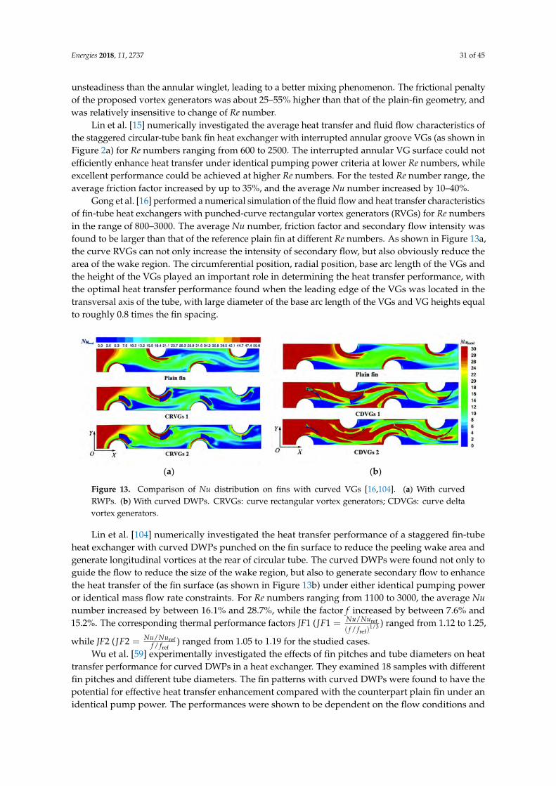
Energies 2018, 11, 2737 31 of 45
unsteadiness than the annular winglet, leading to a better mixing phenomenon. The frictional penaltyof the proposed vortex generators was about 25–55% higher than that of the plain-fin geometry, andwas relatively insensitive to change of Re number.
Lin et al. [15] numerically investigated the average heat transfer and fluid flow characteristics ofthe staggered circular-tube bank fin heat exchanger with interrupted annular groove VGs (as shown inFigure 2a) for Re numbers ranging from 600 to 2500. The interrupted annular VG surface could notefficiently enhance heat transfer under identical pumping power criteria at lower Re numbers, whileexcellent performance could be achieved at higher Re numbers. For the tested Re number range, theaverage friction factor increased by up to 35%, and the average Nu number increased by 10–40%.
Gong et al. [16] performed a numerical simulation of the fluid flow and heat transfer characteristicsof fin-tube heat exchangers with punched-curve rectangular vortex generators (RVGs) for Re numbersin the range of 800–3000. The average Nu number, friction factor and secondary flow intensity wasfound to be larger than that of the reference plain fin at different Re numbers. As shown in Figure 13a,the curve RVGs can not only increase the intensity of secondary flow, but also obviously reduce thearea of the wake region. The circumferential position, radial position, base arc length of the VGs andthe height of the VGs played an important role in determining the heat transfer performance, withthe optimal heat transfer performance found when the leading edge of the VGs was located in thetransversal axis of the tube, with large diameter of the base arc length of the VGs and VG heights equalto roughly 0.8 times the fin spacing.
Energies 2018, 11, x FOR PEER REVIEW 27 of 41
geometry, except for the cases with one tube row, larger fin pitches and lower frontal velocities. The difference increased with rising velocity, but the difference was smaller at a larger fin pitch. The comparatively effectively swirled motion of the semi-dimple VG charged the increased difference.
4.2.3. Performance of Recently Proposed Vortex Generators
Wang et al. [6,9] presented the flow visualization and frictional results of enlarged fin-tube heat exchangers with annular and delta winglet VGs at Re numbers between 500 and 3000. With the presence of annular VGs, a pair of longitudinal vortices formed behind the tube and the strength of the counter-rotating vortices increased with the annular height. The strength of the longitudinal vortices was so strong that they may swirl with the horseshoe vortices and other flow stream. For the same winglet height, the delta winglet was found to have more-intensely vorticial motion and flow unsteadiness than the annular winglet, leading to a better mixing phenomenon. The frictional penalty of the proposed vortex generators was about 25–55% higher than that of the plain-fin geometry, and was relatively insensitive to change of Re number.
Lin et al. [15] numerically investigated the average heat transfer and fluid flow characteristics of the staggered circular-tube bank fin heat exchanger with interrupted annular groove VGs (as shown in Figure 2a) for Re numbers ranging from 600 to 2500. The interrupted annular VG surface could not efficiently enhance heat transfer under identical pumping power criteria at lower Re numbers, while excellent performance could be achieved at higher Re numbers. For the tested Re number range, the average friction factor increased by up to 35%, and the average Nu number increased by 10–40%.
Gong et al. [16] performed a numerical simulation of the fluid flow and heat transfer characteristics of fin-tube heat exchangers with punched-curve rectangular vortex generators (RVGs) for Re numbers in the range of 800–3000. The average Nu number, friction factor and secondary flow intensity was found to be larger than that of the reference plain fin at different Re numbers. As shown in Figure 13a, the curve RVGs can not only increase the intensity of secondary flow, but also obviously reduce the area of the wake region. The circumferential position, radial position, base arc length of the VGs and the height of the VGs played an important role in determining the heat transfer performance, with the optimal heat transfer performance found when the leading edge of the VGs was located in the transversal axis of the tube, with large diameter of the base arc length of the VGs and VG heights equal to roughly 0.8 times the fin spacing.
(a) (b)
Figure 13. Comparison of Nu distribution on fins with curved VGs [16,104]. (a) With curved RWPs. (b) With curved DWPs. CRVGs: curve rectangular vortex generators; CDVGs: curve delta vortex generators.
Lin et al. [104] numerically investigated the heat transfer performance of a staggered fin-tube heat exchanger with curved DWPs punched on the fin surface to reduce the peeling wake area and generate longitudinal vortices at the rear of circular tube. The curved DWPs were found not only to guide the flow to reduce the size of the wake region, but also to generate secondary flow to enhance the heat transfer of the fin surface (as shown in Figure 13b) under either identical pumping power or
Figure 13. Comparison of Nu distribution on fins with curved VGs [16,104]. (a) With curvedRWPs. (b) With curved DWPs. CRVGs: curve rectangular vortex generators; CDVGs: curve deltavortex generators.
Lin et al. [104] numerically investigated the heat transfer performance of a staggered fin-tubeheat exchanger with curved DWPs punched on the fin surface to reduce the peeling wake area andgenerate longitudinal vortices at the rear of circular tube. The curved DWPs were found not only toguide the flow to reduce the size of the wake region, but also to generate secondary flow to enhancethe heat transfer of the fin surface (as shown in Figure 13b) under either identical pumping poweror identical mass flow rate constraints. For Re numbers ranging from 1100 to 3000, the average Nunumber increased by between 16.1% and 28.7%, while the factor f increased by between 7.6% and15.2%. The corresponding thermal performance factors JF1 (JF1 = Nu/Nuref
( f / fref)1/3 ) ranged from 1.12 to 1.25,
while JF2 (JF2 = Nu/Nureff / fref
) ranged from 1.05 to 1.19 for the studied cases.Wu et al. [59] experimentally investigated the effects of fin pitches and tube diameters on heat
transfer performance for curved DWPs in a heat exchanger. They examined 18 samples with differentfin pitches and different tube diameters. The fin patterns with curved DWPs were found to have thepotential for effective heat transfer enhancement compared with the counterpart plain fin under anidentical pump power. The performances were shown to be dependent on the flow conditions and
Energies 2018, 11, 2737 32 of 45
the fin’s geometry parameters. The correlations of Nu number and factor f with Re number, fin collaroutside diameter (D) and fin pitch (T) were obtained for the studied Re number range from 500 to 4200.
For the plain fin:
Nu = 0.1317Re0.6130(T
Tref)
0.3244(
DDref
)0.1482
(5)
f = 0.8918Re−0.2350(T
Tref)
0.7381(
DDref
)0.1527
(6)
For the fin with curved DWPs:
Nu = 0.1874Re0.5883(T
Tref)
0.2722(
DDref
)−0.3062
(7)
f = 1.17Re−0.2507(T
Tref)
0.6142(
DDref
)−0.4182
(8)
where the counterpart plain fin without VGs was selected as a reference for comparison.He et al. [17] experimentally investigated the heat transfer enhancement by V-deployed VG arrays
as shown in Figure 2b in a fin-tube heat exchanger for Re numbers in the range of 1400 to 3400. The 10
VG array induced little thermal improvement, the small pair resulted in heat transfer improvement ofup to 32%, and both introduced additional pressure loss of approximately 20–40%. The 30 VG arrayand the large pair similarly led to augmentation of 25–55% associated with average pressure-droppenalties of 90% and 140%, respectively, indicating that the 30 VG array reduced the wake zone ofthe trailing winglet and mitigates the pressure difference between its fore and aft sides. Performanceevaluation using the criteria of the modified area goodness factor (j/f 1/3 versus Re) and the volumegoodness factor (the heat transfer coefficient versus the pumping power per unit heat transfer area)indicated the superiority of the heat exchanger with the 30 VG array.
He et al. [92] examined the heat transfer performance of two DWPs with two layout modes ofcontinuous and discontinuous winglets for Re numbers ranging from 600 to 2600, and investigatedthe effects of different geometry parameters including the angle (α = 10, 20, 30) and the layoutlocations. The VG arrays were found to generate more vortices, and the vortices influenced each other.The vortices generated by the continuous small winglet array can weaken the swirling movementof the fluid. The vortices generated by the large winglets can even affect the whole region along thefin channel height. The increase of angle α resulted in the increase of both heat transfer coefficientand pressure drop, and the arrays with discontinuous winglets for the 30 case showed the best heattransfer enhancement with a significant augmentation of up to 33.8–70.6% in heat transfer coefficientwith a pressure-drop penalty of 43.4–97.2% compared to the plain fin.
Huisseune et al. [95] numerically studied the thermohydraulic performance of a compound heatexchanger with louvre and DWPs for Re numbers ranging from 220 to 915. As shown in Figure 14, asmall fin pitch and large louvre angle caused a strong flow deflection and thus a large contributionof the louvres, but in this case, the generation of longitudinal vortices was suppressed, and thus theeffect of the delta winglets was very small, while the delta winglet geometry itself had an importantinfluence for plate-fin-tube heat exchangers.
Wu et al. [22] investigated the heat transfer and fluid flow performance of the composite finwith DWPs and slit fin as shown in Figure 2e for Re numbers ranging from 304 to 2130. The eddiesdeveloped behind the X-shaped slit and delta winglet, which not only decreased the wake regionsize, but also increased the flow velocity in the wake zone, and thus produced some disruptions tofluid flow and enhance heat transfer, leading to better heat transfer performance of the composite fincompared with the plain fin and slit fin. In contrast to the heat exchanger with a plain fin or slit fin, theheat transfer of that with the composite fin can be improved by 77.16–90.21% or 6–36%, and the overallperformance can be increased by 26.18–50.89% or 45–14%.

Energies 2018, 11, 2737 33 of 45
Energies 2018, 11, x FOR PEER REVIEW 29 of 41
effect of the delta winglets was very small, while the delta winglet geometry itself had an important influence for plate-fin-tube heat exchangers.
Figure 14. Velocity contours in a compound fin with louvre and DWPs for Vin = 1.26 m/s [95].
Wu et al. [22] investigated the heat transfer and fluid flow performance of the composite fin with DWPs and slit fin as shown in Figure 2e for Re numbers ranging from 304 to 2130. The eddies developed behind the X-shaped slit and delta winglet, which not only decreased the wake region size, but also increased the flow velocity in the wake zone, and thus produced some disruptions to fluid flow and enhance heat transfer, leading to better heat transfer performance of the composite fin compared with the plain fin and slit fin. In contrast to the heat exchanger with a plain fin or slit fin, the heat transfer of that with the composite fin can be improved by 77.16–90.21% or 6–36%, and the overall performance can be increased by 26.18–50.89% or 45–14%.
4.3. Vortex Generators in Finned Flat-Tube Heat Exchangers
Fiebig et al. [29] measured the heat transfer performance of DWPs in fin-tube heat exchangers with either flat or circle tubes in a staggered arrangement for a Re number range of 600 to 3000. As shown in Figure 15, the DWPs did not have much influence on either the location or the value of this peak for circle tubes, while resulted in dramatically increased Nu numbers in both peak values and fin areas for flat tubes. Nu number peaks for the flat tubes appeared in front of the tubes and at the trailing edge of the DWPs, while they only appeared in front of the tubes for the circle tubes, and were also not as dramatic as those for the flat tubes, because the zone of influence of the longitudinal vortices on the fin was much larger for the flat tubes than for the circle tubes. The heat exchanger element with the flat tubes and DWPs was found to provide nearly twice as much heat transfer and only half as much pressure loss as the corresponding heat exchanger element with round tubes.
Yoo et al. [36] compared the thermohydraulic performances of the staggered flat and circle tube heat exchangers with RWPs for Re numbers varying from 800 to 4500. Average heat transfer coefficients of fin-flat-tube heat exchangers without VGs were much lower than those of fin-circular-tube heat exchangers, but fin-flat-tube heat exchangers with VGs had much higher heat transfer value than fin-circular-tube heat exchangers, where the overall average heat transfer coefficient with VGs increased by 75% and 45%, respectively for fin-flat-tube and fin-circle-tube heat exchangers, compared to those without VGs. The fin-flat-tube heat exchangers with VGs were also found to have higher heat transfer efficiency and lower pressure loss than the fin-circular-tube heat exchangers.
Allison and Dally [44] compared the heat transfer performance of a fin-flat-tube heat exchanger with DWPs to a standard louvre fin surface and found that the DWPs had 87% of the heat transfer capacity, but only 53% of the pressure drop of the louvre fin surface.
Figure 14. Velocity contours in a compound fin with louvre and DWPs for Vin = 1.26 m/s [95].
4.3. Vortex Generators in Finned Flat-Tube Heat Exchangers
Fiebig et al. [29] measured the heat transfer performance of DWPs in fin-tube heat exchangers witheither flat or circle tubes in a staggered arrangement for a Re number range of 600 to 3000. As shownin Figure 15, the DWPs did not have much influence on either the location or the value of this peak forcircle tubes, while resulted in dramatically increased Nu numbers in both peak values and fin areas forflat tubes. Nu number peaks for the flat tubes appeared in front of the tubes and at the trailing edgeof the DWPs, while they only appeared in front of the tubes for the circle tubes, and were also not asdramatic as those for the flat tubes, because the zone of influence of the longitudinal vortices on thefin was much larger for the flat tubes than for the circle tubes. The heat exchanger element with theflat tubes and DWPs was found to provide nearly twice as much heat transfer and only half as muchpressure loss as the corresponding heat exchanger element with round tubes.
Energies 2018, 11, x FOR PEER REVIEW 30 of 41
Shi et al. [43] focused on the optimal fin spacing (T) for three-row flat-tube bank fins mounted with DWPs. It was found that increasing the fin spacing resulted in a decrease in both average Nu number and factor f, and the optimal fin spacing of about 2 mm in industrial application for the studied configuration of tube bank was suggested based on the performance factor
ref1/ 3 1/ 3
ref ref
/
( / ) ( / )
j jJF
f f T T= .
(a) (b)
Figure 15. Span-averaged fin Nu number for different fin-tube heat exchangers [29]. (a) For round tubes without and with VGs. (b) For flat tubes without and with VGs.
Song et al. [81] studied heat transfer enhancement of a fin-tube heat exchanger with DWPs mounted on both surfaces of the fin for Re numbers between 200 and 1900. DWPs mounted on both surfaces can significantly enhance heat transfer on the fin, but the enhancement depends on the height of the DWPs, whereby large height usually contributes larger enhancement, but is also associated with too high a cost in terms of pumping power, and DWPs with small height mounted on both surfaces of the fin can lead to heat transfer enhancement with less power cost.
Chang et al. [82] numerically studied the relationship between the intensity of the secondary flow and the strength of convective heat transfer in a channel formed by a flat-tube bank with DWPs for Re numbers ranging 300 to 1700. The secondary flow was found not to greatly change the boundary layer characteristics, particularly for beginning region of boundary layer. A cross-averaged
absolute vorticity flux ( nABS
n
AdA
JA
ω= , ω is the vorticity) was proposed to account for the secondary
flow effects on the convective heat transfer. However, it could not quantify the effects of developing boundary layer.
Song and Wang [98] developed nondimensional parameters of ratio of inertial force to viscous
force induced by secondary flow (cross-section-average value 2
s
n
Ad dA
SeA
ρ ωμ
= and volume
average value2
m
n
Vd dV
SeV
ρ ωμ
= ) based on the absolute vorticity flux to specify the intensity of
secondary flow. Close relationships were found not only between the span-average parameter Ses and the span-average Nu number but also between the volume average parameter Sem and the overall average Nu number. For the studied configurations under the periodically fully developed heat
Figure 15. Span-averaged fin Nu number for different fin-tube heat exchangers [29]. (a) For roundtubes without and with VGs. (b) For flat tubes without and with VGs.

Energies 2018, 11, 2737 34 of 45
Yoo et al. [36] compared the thermohydraulic performances of the staggered flat and circle tubeheat exchangers with RWPs for Re numbers varying from 800 to 4500. Average heat transfer coefficientsof fin-flat-tube heat exchangers without VGs were much lower than those of fin-circular-tube heatexchangers, but fin-flat-tube heat exchangers with VGs had much higher heat transfer value thanfin-circular-tube heat exchangers, where the overall average heat transfer coefficient with VGs increasedby 75% and 45%, respectively for fin-flat-tube and fin-circle-tube heat exchangers, compared to thosewithout VGs. The fin-flat-tube heat exchangers with VGs were also found to have higher heat transferefficiency and lower pressure loss than the fin-circular-tube heat exchangers.
Allison and Dally [44] compared the heat transfer performance of a fin-flat-tube heat exchangerwith DWPs to a standard louvre fin surface and found that the DWPs had 87% of the heat transfercapacity, but only 53% of the pressure drop of the louvre fin surface.
Shi et al. [43] focused on the optimal fin spacing (T) for three-row flat-tube bank fins mountedwith DWPs. It was found that increasing the fin spacing resulted in a decrease in both average Nunumber and factor f, and the optimal fin spacing of about 2 mm in industrial application for the studiedconfiguration of tube bank was suggested based on the performance factor JF = j/jref
( f / fref)1/3(T/Tref)
1/3 .
Song et al. [81] studied heat transfer enhancement of a fin-tube heat exchanger with DWPsmounted on both surfaces of the fin for Re numbers between 200 and 1900. DWPs mounted on bothsurfaces can significantly enhance heat transfer on the fin, but the enhancement depends on the heightof the DWPs, whereby large height usually contributes larger enhancement, but is also associated withtoo high a cost in terms of pumping power, and DWPs with small height mounted on both surfaces ofthe fin can lead to heat transfer enhancement with less power cost.
Chang et al. [82] numerically studied the relationship between the intensity of the secondary flowand the strength of convective heat transfer in a channel formed by a flat-tube bank with DWPs for Renumbers ranging 300 to 1700. The secondary flow was found not to greatly change the boundary layercharacteristics, particularly for beginning region of boundary layer. A cross-averaged absolute vorticity
flux (JnABS =
sA ωndA
A , ω is the vorticity) was proposed to account for the secondary flow effects on theconvective heat transfer. However, it could not quantify the effects of developing boundary layer.
Song and Wang [98] developed nondimensional parameters of ratio of inertial force to viscous
force induced by secondary flow (cross-section-average value Ses =ρd2s
A |ωn |dA
µA and volume average
value Sem =ρd2s
V |ωn |dV
µV ) based on the absolute vorticity flux to specify the intensity of secondary flow.Close relationships were found not only between the span-average parameter Ses and the span-averageNu number but also between the volume average parameter Sem and the overall average Nu number.For the studied configurations under the periodically fully developed heat transfer and fluid flowconditions, the correlations of Sem, average Nu and average friction factor f with Re were developed.For a channel with mounted VGs:
Sem = 0.0941Re1.3427 (9)
Nu = 0.21344Re0.57855 (10)
f = 8.4127Re−0.5570 (11)
For the plain-fin channel:Sem = 0.0973Re1.2939 (12)
Nu = 0.1023Re0.6186 (13)
f = 25.8040Re−0.7829 (14)
4.4. Vortex Generators in Finned Oval-Tube Heat Exchanger
Chen et al. [71] numerically investigated the thermohydraulic performance of finned oval-tubeheat exchanger elements with two to four staggered DWPs (α = 30, Λ = 2, h = H, h and H are the
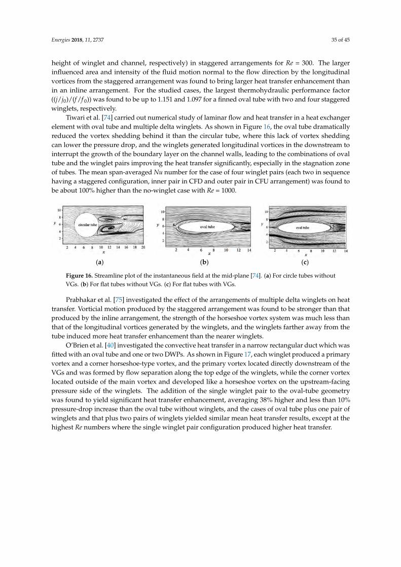
Energies 2018, 11, 2737 35 of 45
height of winglet and channel, respectively) in staggered arrangements for Re = 300. The largerinfluenced area and intensity of the fluid motion normal to the flow direction by the longitudinalvortices from the staggered arrangement was found to bring larger heat transfer enhancement thanin an inline arrangement. For the studied cases, the largest thermohydraulic performance factor((j/j0)/(f /f 0)) was found to be up to 1.151 and 1.097 for a finned oval tube with two and four staggeredwinglets, respectively.
Tiwari et al. [74] carried out numerical study of laminar flow and heat transfer in a heat exchangerelement with oval tube and multiple delta winglets. As shown in Figure 16, the oval tube dramaticallyreduced the vortex shedding behind it than the circular tube, where this lack of vortex sheddingcan lower the pressure drop, and the winglets generated longitudinal vortices in the downstream tointerrupt the growth of the boundary layer on the channel walls, leading to the combinations of ovaltube and the winglet pairs improving the heat transfer significantly, especially in the stagnation zoneof tubes. The mean span-averaged Nu number for the case of four winglet pairs (each two in sequencehaving a staggered configuration, inner pair in CFD and outer pair in CFU arrangement) was found tobe about 100% higher than the no-winglet case with Re = 1000.
Energies 2018, 11, x FOR PEER REVIEW 31 of 41
transfer and fluid flow conditions, the correlations of Sem, average Nu and average friction factor f with Re were developed. For a channel with mounted VGs:
1.3427m 0.0941Se Re= (9)
0.578550.21344Nu Re= (10) 0.55708.4127f Re−= (11)
For the plain-fin channel: 1.2939
m 0.0973Se Re= (12) 0.61860.1023Nu Re= (13) 0.782925.8040f Re−= (14)
4.4. Vortex Generators in Finned Oval-Tube Heat Exchanger
Chen et al. [71] numerically investigated the thermohydraulic performance of finned oval-tube heat exchanger elements with two to four staggered DWPs (α = 30°, Λ = 2, h = H, h and H are the height of winglet and channel, respectively) in staggered arrangements for Re = 300. The larger influenced area and intensity of the fluid motion normal to the flow direction by the longitudinal vortices from the staggered arrangement was found to bring larger heat transfer enhancement than in an inline arrangement. For the studied cases, the largest thermohydraulic performance factor ((j/j0)/(f/f0)) was found to be up to 1.151 and 1.097 for a finned oval tube with two and four staggered winglets, respectively.
Tiwari et al. [74] carried out numerical study of laminar flow and heat transfer in a heat exchanger element with oval tube and multiple delta winglets. As shown in Figure 16, the oval tube dramatically reduced the vortex shedding behind it than the circular tube, where this lack of vortex shedding can lower the pressure drop, and the winglets generated longitudinal vortices in the downstream to interrupt the growth of the boundary layer on the channel walls, leading to the combinations of oval tube and the winglet pairs improving the heat transfer significantly, especially in the stagnation zone of tubes. The mean span-averaged Nu number for the case of four winglet pairs (each two in sequence having a staggered configuration, inner pair in CFD and outer pair in CFU arrangement) was found to be about 100% higher than the no-winglet case with Re = 1000.
(a) (b) (c)
Figure 16. Streamline plot of the instantaneous field at the mid-plane [74]. (a) For circle tubes without VGs. (b) For flat tubes without VGs. (c) For flat tubes with VGs.
Prabhakar et al. [75] investigated the effect of the arrangements of multiple delta winglets on heat transfer. Vorticial motion produced by the staggered arrangement was found to be stronger than that produced by the inline arrangement, the strength of the horseshoe vortex system was much less than that of the longitudinal vortices generated by the winglets, and the winglets farther away from the tube induced more heat transfer enhancement than the nearer winglets.
O’Brien et al. [40] investigated the convective heat transfer in a narrow rectangular duct which was fitted with an oval tube and one or two DWPs. As shown in Figure 17, each winglet produced a primary vortex and a corner horseshoe-type vortex, and the primary vortex located directly downstream of the VGs and was formed by flow separation along the top edge of the winglets, while
Figure 16. Streamline plot of the instantaneous field at the mid-plane [74]. (a) For circle tubes withoutVGs. (b) For flat tubes without VGs. (c) For flat tubes with VGs.
Prabhakar et al. [75] investigated the effect of the arrangements of multiple delta winglets on heattransfer. Vorticial motion produced by the staggered arrangement was found to be stronger than thatproduced by the inline arrangement, the strength of the horseshoe vortex system was much less thanthat of the longitudinal vortices generated by the winglets, and the winglets farther away from thetube induced more heat transfer enhancement than the nearer winglets.
O’Brien et al. [40] investigated the convective heat transfer in a narrow rectangular duct which wasfitted with an oval tube and one or two DWPs. As shown in Figure 17, each winglet produced a primaryvortex and a corner horseshoe-type vortex, and the primary vortex located directly downstream of theVGs and was formed by flow separation along the top edge of the winglets, while the corner vortexlocated outside of the main vortex and developed like a horseshoe vortex on the upstream-facingpressure side of the winglets. The addition of the single winglet pair to the oval-tube geometrywas found to yield significant heat transfer enhancement, averaging 38% higher and less than 10%pressure-drop increase than the oval tube without winglets, and the cases of oval tube plus one pair ofwinglets and that plus two pairs of winglets yielded similar mean heat transfer results, except at thehighest Re numbers where the single winglet pair configuration produced higher heat transfer.
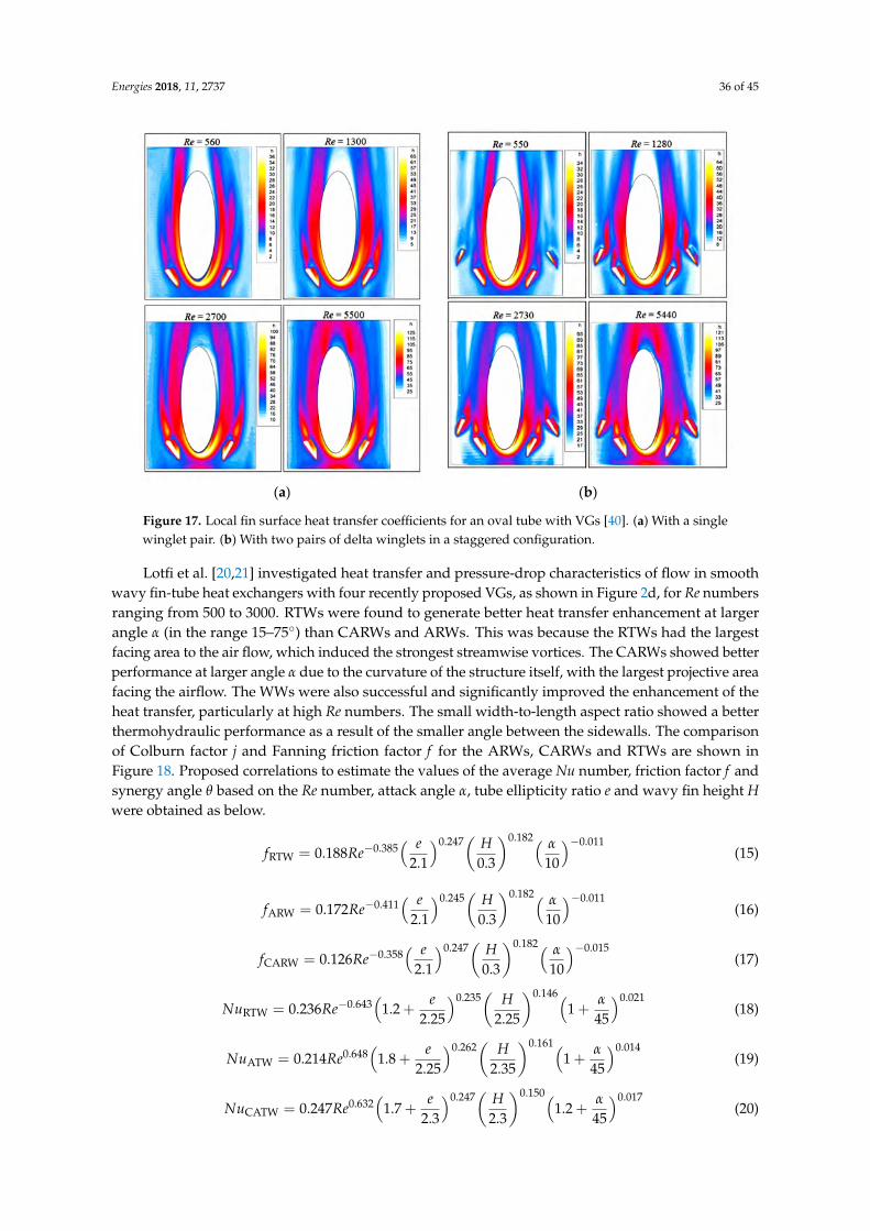
Energies 2018, 11, 2737 36 of 45
Energies 2018, 11, x FOR PEER REVIEW 32 of 41
the corner vortex located outside of the main vortex and developed like a horseshoe vortex on the upstream-facing pressure side of the winglets. The addition of the single winglet pair to the oval-tube geometry was found to yield significant heat transfer enhancement, averaging 38% higher and less than 10% pressure-drop increase than the oval tube without winglets, and the cases of oval tube plus one pair of winglets and that plus two pairs of winglets yielded similar mean heat transfer results, except at the highest Re numbers where the single winglet pair configuration produced higher heat transfer.
(a) (b)
Figure 17. Local fin surface heat transfer coefficients for an oval tube with VGs [40]. (a) With a single winglet pair. (b) With two pairs of delta winglets in a staggered configuration.
Lotfi et al. [20,21] investigated heat transfer and pressure-drop characteristics of flow in smooth wavy fin-tube heat exchangers with four recently proposed VGs, as shown in Figure 2d, for Re numbers ranging from 500 to 3000. RTWs were found to generate better heat transfer enhancement at larger angle α (in the range 15–75°) than CARWs and ARWs. This was because the RTWs had the largest facing area to the air flow, which induced the strongest streamwise vortices. The CARWs showed better performance at larger angle α due to the curvature of the structure itself, with the largest projective area facing the airflow. The WWs were also successful and significantly improved the enhancement of the heat transfer, particularly at high Re numbers. The small width-to-length aspect ratio showed a better thermohydraulic performance as a result of the smaller angle between the sidewalls. The comparison of Colburn factor j and Fanning friction factor f for the ARWs, CARWs and RTWs are shown in Figure 18. Proposed correlations to estimate the values of the average Nu number, friction factor f and synergy angle θ based on the Re number, attack angle α, tube ellipticity ratio e and wavy fin height H were obtained as below.
0.247 0.182 0.011
0.385RTW 0.188
2.1 0.3 10
e Hf Re
α −− =
(15)
0.245 0.182 0.011
0.411ARW 0.172
2.1 0.3 10
e Hf Re
α −− =
(16)
0.247 0.182 0.015
0.358CARW 0.126
2.1 0.3 10
e Hf Re
α −− =
(17)
Figure 17. Local fin surface heat transfer coefficients for an oval tube with VGs [40]. (a) With a singlewinglet pair. (b) With two pairs of delta winglets in a staggered configuration.
Lotfi et al. [20,21] investigated heat transfer and pressure-drop characteristics of flow in smoothwavy fin-tube heat exchangers with four recently proposed VGs, as shown in Figure 2d, for Re numbersranging from 500 to 3000. RTWs were found to generate better heat transfer enhancement at largerangle α (in the range 15–75) than CARWs and ARWs. This was because the RTWs had the largestfacing area to the air flow, which induced the strongest streamwise vortices. The CARWs showed betterperformance at larger angle α due to the curvature of the structure itself, with the largest projective areafacing the airflow. The WWs were also successful and significantly improved the enhancement of theheat transfer, particularly at high Re numbers. The small width-to-length aspect ratio showed a betterthermohydraulic performance as a result of the smaller angle between the sidewalls. The comparisonof Colburn factor j and Fanning friction factor f for the ARWs, CARWs and RTWs are shown inFigure 18. Proposed correlations to estimate the values of the average Nu number, friction factor f andsynergy angle θ based on the Re number, attack angle α, tube ellipticity ratio e and wavy fin height Hwere obtained as below.
fRTW = 0.188Re−0.385( e
2.1
)0.247(
H0.3
)0.182( α
10
)−0.011(15)
fARW = 0.172Re−0.411( e
2.1
)0.245(
H0.3
)0.182( α
10
)−0.011(16)
fCARW = 0.126Re−0.358( e
2.1
)0.247(
H0.3
)0.182( α
10
)−0.015(17)
NuRTW = 0.236Re−0.643(
1.2 +e
2.25
)0.235(
H2.25
)0.146(1 +
α
45
)0.021(18)
NuATW = 0.214Re0.648(
1.8 +e
2.25
)0.262(
H2.35
)0.161(1 +
α
45
)0.014(19)
NuCATW = 0.247Re0.632(
1.7 +e
2.3
)0.247(
H2.3
)0.150(1.2 +
α
45
)0.017(20)

Energies 2018, 11, 2737 37 of 45
for 500 ≤ Re ≤ 3000, 15 ≤ α ≤ 75, 0.65 ≤ e ≤ 1, and 0.8 mm ≤ H ≤ 1.6 mm.
Energies 2018, 11, x FOR PEER REVIEW 33 of 41
0.235 0.146 0.021
0.643RTW 0.236 1.2 1
2.25 2.25 45
e HNu Re
α− = + +
(18)
0.262 0.161 0.014
0.648ATW 0.214 1.8 1
2.25 2.35 45
e HNu Re
α = + +
(19)
0.247 0.150 0.017
0.632CATW 0.247 1.7 1.2
2.3 2.3 45
e HNu Re
α = + +
(20)
for 500 ≤ Re ≤ 3000, 15° ≤ α ≤ 75°, 0.65 ≤ e ≤ 1, and 0.8 mm ≤ H ≤ 1.6 mm.
(a) (b)
Figure 18. Effects on Colburn factor j and friction factor f at attack angles 30° and 60° [20]. (a) Colburn factor j. (b) Friction factor f. RTW: rectangular trapezoidal winglet; ARW: angle rectangular winglet; CARW: curved angle rectangular winglet.
5. Concluding Remarks
The airside thermohydraulic performance of heat transfer surfaces associated with VGs has been reviewed for the purpose of generating a better understanding of the complex interactions of flow and heat transfer and the goal of developing higher-performance heat transfer surfaces for specific applications. Different types of VGs are reported, with particular attention to VGs developed in recent years. Key experimental techniques and numerical methodologies are summarized, with special attention to flow visualization and local heat transfer measurement. Flow phenomena and thermohydraulic performance are studied for different heat transfer surfaces employing VGs attached on flat plates and VGs mounted on fins in finned tube heat exchangers. The effects of the geometry parameters of the heat transfer surfaces and flow conditions on the thermohydraulic performance are presented and discussed. Furthermore, special attention is given to the thermohydraulic performance of the heat transfer surfaces with recently proposed VGs. The key findings in the paper are following.
VGs attached on flat plates lead to heat transfer enhancement by the mixing of fluid between the wall and the core region for a laminar flow and the secondary flow and the frequent boundary layer interruptions for a turbulent flow. VGs mounted on finned tube heat exchangers can significantly improve the overall performance due to the nozzle-like flow passages and the strong swirling motion originating from the streamwise longitudinal vortices those result in the enhancement of the thermal mixing of the fluid, a delay of the boundary layer separation and a reduction of the size of the tube wake. Finned flat-tube heat exchanger with VGs can have higher heat transfer potential than finned circular-tube heat exchangers; this can be attributed to the horseshoe vortices formed around the tube, which enhance the heat transfer considerably. The combinations of oval tube and VGs can improve the heat transfer significantly, especially in the stagnation zone of tubes, due to the lack of vortex shedding behind oval tubes and generated longitudinal vortices in the downstream of the VGs. All studies (analytic, numerical and experimental) show that both heat transfer and pressure drop increase with Re number, and the overall performance of heat transfer surfaces with VGs usually
Figure 18. Effects on Colburn factor j and friction factor f at attack angles 30 and 60 [20]. (a) Colburnfactor j. (b) Friction factor f. RTW: rectangular trapezoidal winglet; ARW: angle rectangular winglet;CARW: curved angle rectangular winglet.
5. Concluding Remarks
The airside thermohydraulic performance of heat transfer surfaces associated with VGs hasbeen reviewed for the purpose of generating a better understanding of the complex interactionsof flow and heat transfer and the goal of developing higher-performance heat transfer surfaces forspecific applications. Different types of VGs are reported, with particular attention to VGs developedin recent years. Key experimental techniques and numerical methodologies are summarized, withspecial attention to flow visualization and local heat transfer measurement. Flow phenomena andthermohydraulic performance are studied for different heat transfer surfaces employing VGs attachedon flat plates and VGs mounted on fins in finned tube heat exchangers. The effects of the geometryparameters of the heat transfer surfaces and flow conditions on the thermohydraulic performance arepresented and discussed. Furthermore, special attention is given to the thermohydraulic performanceof the heat transfer surfaces with recently proposed VGs. The key findings in the paper are following.
VGs attached on flat plates lead to heat transfer enhancement by the mixing of fluid betweenthe wall and the core region for a laminar flow and the secondary flow and the frequent boundarylayer interruptions for a turbulent flow. VGs mounted on finned tube heat exchangers can significantlyimprove the overall performance due to the nozzle-like flow passages and the strong swirling motionoriginating from the streamwise longitudinal vortices those result in the enhancement of the thermalmixing of the fluid, a delay of the boundary layer separation and a reduction of the size of thetube wake. Finned flat-tube heat exchanger with VGs can have higher heat transfer potential thanfinned circular-tube heat exchangers; this can be attributed to the horseshoe vortices formed aroundthe tube, which enhance the heat transfer considerably. The combinations of oval tube and VGscan improve the heat transfer significantly, especially in the stagnation zone of tubes, due to thelack of vortex shedding behind oval tubes and generated longitudinal vortices in the downstreamof the VGs. All studies (analytic, numerical and experimental) show that both heat transfer andpressure drop increase with Re number, and the overall performance of heat transfer surfaces with VGsusually improves with an increase in Re number, but that the rate of heat transfer coefficient increasereduces with Re number. Many investigations focused on VGs attached on flat plates and finnedcircular-tube heat exchangers, while few studies concentrated on VGs mounted in finned flat-tubeand finned oval-tube heat exchangers. The indications of heat transfer augmentation are usuallydimensionless factors comparing the heat transfer and fluid friction, including j/j0, f /f 0, (j/j0)/(f /f 0),(Nu/Nu0)/(f /f 0), j/f 1/3, (j/j0)/(f /f 0)1/3, (Nu/Nu0)/(f /f 0)1/3. From a thermodynamic point of view,j/f 1/3, (j/j0)/(f /f 0)1/3, (Nu/Nu0)/(f /f 0)1/3 are recommended for performance evaluation. The VG
Energies 2018, 11, 2737 38 of 45
type, attack angle, attack angle ratio and configurations of the tube and VGs can have importantinfluences on the overall performance and show combined effects. Winglets are usually more effectivethan the wings and delta pairs are commonly a little more efficient than rectangular pairs. The increaseof attack angle and attack angle ratio up to a maximum commonly leads to improvement of heattransfer enhancement. The tube row configuration with changed diameters can result in betterthermohydraulic performance. Recently proposed vortex generators, including rectangular wings withthe four corners cut off, interrupted annular VGs, V-deployed VG arrays, curved generator surfaces,punched holes, compound surfaces and DWPs in CFU arrangement, can all result in improved overallthermohydraulic performance of heat transfer surfaces compared with those employing traditionalVGs. In conclusion, fundamental understanding of the interactions of flow and heat transfer causedby VGs in extended surface heat exchangers has been indicated, and the most important designcorrelations for the optimal performance have been established.
6. Recommendations for Future Works
Based on the investigations published on airside heat transfer augmentation on heat transfersurfaces using vortex generators, several suggestions and recommendations are listed for future works.In comparison to finned circular-tube heat exchangers with VGs, finned flat-tube and finned oval-tubeheat exchangers with VGs are expected to have a smaller airside pressure drop and improved airsideheat transfer coefficients; therefore, more effort should be made to conduct experiments and simulationsover a wider range of test parameters for these two types of heat exchanger. Further research needsto be carried out to develop the universal design correlations for the optimal performance of heatexchangers using VGs in the extended surfaces. When investigators develop these correlations, it isstrongly suggested that the geometry parameters and the data reduction methods are clearly addressed.In addition, before using certain correlations, the designer and engineer should carefully examinethe detailed data of heat transfer surface geometry and operation condition and the applicabilityand limitation of the correlation. The present optimization of heat exchange is often based onthermohydraulic performance, but manufacturing difficulty and fin efficiency must always be bornein mind. Therefore, optimization methods with cost-based objective functions that consider thethermohydraulic performance and capital cost reduction, as well as safety and compliance withrelevant international standards, are recommended. Considering that the heat exchanger is a vitalthermodynamic system component and its thermohydraulic performance is a key parameter in overallsystem design, more work is required on the influence of the improved heat transfer surfaces on thewhole system size and lifecycle cost.
Author Contributions: L.C. performed most of the bibliographic review and prepared the original draft of thework. S.A.T. reviewed and provided comments on the different versions of the paper and obtained the fundingthat supported the work.
Funding: This research received funding from the UK Engineering and Physical Sciences Research Council(EPSRC), under grant numbers EP/P004636/1 and EP/K011820/1, and the European Union’s Horizon 2020research and innovation programme grant number No. 680599.
Acknowledgments: The authors would like to acknowledge the financial support received by the project fundersand the industry partners. All data used are included in the paper but if any additional information is required itcan be obtained by contacting the corresponding author.
Conflicts of Interest: The authors declare no conflict of interest.
Nomenclature
a geometry parameterA area, m2
b geometry parameterc geometry parametercp specific heat, J·kg−1·K−1
CD drag coefficient

Energies 2018, 11, 2737 39 of 45
d diameter, mD total drag force, NDh hydraulic diameter, me ellipticity ratioE fan power per unit core volumef friction factor; frequency, Hz; formulah heat transfer coefficient, W·m−2·K−1; height, mH height, m; distance between two plates, mj Colburn factorJ vorticity fluxk thermal conductivity, W·m−1·K−1
L length, mNu Nusselt numberp pressure, PaPe Peclet numberPr Prandtl numberQ quality factorRa area ratioRe Reynolds numberS projected area, m2; Strouhal numberSe dimensionless parameterSt Stanton numberT temperature, Ku velocity, m·s−1
V velocity, m·s−1
x,y,z Cartesian coordinates, mZ heat transfer per unit temperature difference and per unit core volumeGreek lettersα angle of attackβ inclination angle; span angleθ skew angle; momentum thickness of boundary layer, mρ density, kg·m−3
µ dynamic viscosity, Pa·sν kinematic viscosity, m2·s−1
δ thickness, mΛ aspect ratioΓ vortex circulationδ99 boundary layer thicknessΩ goodness factorSubscripts0 referenceb boundary layerc channel; core-to-platee crossj jetm volume averageref references cross-section averagex streamwise directiony transverse directionv vortex generator
Energies 2018, 11, 2737 40 of 45
AbbreviationsARW angle rectangular wingletCARW curved angle rectangular wingletCCD charged coupled deviceCDVGs curve delta vortex generatorsCDW curved delta wingletCFD computational fluid dynamics; common-flow-downCFD-CFD common-flow-down in seriesCFD-CFU combined common-flow-down and common-flow-upCFU common-flow-upCFU-CFU common-flow-up in seriesCRW curved rectangular wingletCRVGs curve rectangular vortex generatorsCTW curved trapezoidal wingletCTWPs curved trapezoidal winglet pairsDW delta wingletDWP delta winglet pairDWPs delta winglet pairsIRW inline rows of wingletLCT liquid crystal thermographyLDV laser doppler velocimetryLLS laser light sheetsMAC marker-and-cellPIV particle image velocimetryRTW rectangular trapezoidal wingletRW rectangular wingletRWP rectangular winglet pairRWPs rectangular winglet pairsRVGs rectangular vortex generatorsSRW staggered rows of wingletTW trapezoidal wingletTWPs trapezoidal winglet pairsVGs vortex generatorsWW wheeler wishbone
References
1. Thulukkanam, K. Heat Exchanger Design Handbook; CRC Press: Boca Raton, FL, USA, 2013.2. Joule, J.P. On the surface-condensation of steam. Philos. Trans. R. Soc. Lond. 1861, 151, 133–160. [CrossRef]3. Wang, C.C. Recent progress on the air-side performance of fin-and-tube heat exchangers. Int. J. Heat Exch.
2000, 1, 49–76.4. Tian, L.; He, Y.; Chu, P.; Tao, W. Numerical study of flow and heat transfer enhancement by using delta
winglets in a triangular wavy fin-and-tube heat exchanger. J. Heat Transf. 2009, 131, 091901. [CrossRef]5. Fiebig, M. Vortices, generators and heat transfer. Chem. Eng. Res. Des. 1998, 76, 108–123. [CrossRef]6. Wang, C.C.; Lo, J.; Lin, Y.T.; Liu, M.S. Flow visualization of wave-type vortex generators having inline
fin-tube arrangement. Int. J. Heat Mass Transf. 2002, 45, 1933–1944. [CrossRef]7. Depaiwa, N.; Chompookham, T.; Promvonge, P. Thermal enhancement in a solar air heater channel using
rectangular winglet vortex generators. In Proceedings of the IEEE 2010 Proceedings of the InternationalConference on Energy and Sustainable Development: Issues and Strategies (ESD), Chiang Mai, Thailand,2–4 June 2010; pp. 1–7.
8. Jacobi, A.M.; Shah, R.K. Heat transfer surface enhancement through the use of longitudinal vortices: A reviewof recent progress. Exp. Therm. Fluid Sci. 1995, 11, 295–309. [CrossRef]
9. Wang, C.C.; Lo, J.; Lin, Y.T.; Wei, C.S. Flow visualization of annular and delta winglet vortex generators infin-and-tube heat exchanger application. Int. J. Heat Mass Transf. 2002, 45, 3803–3815. [CrossRef]
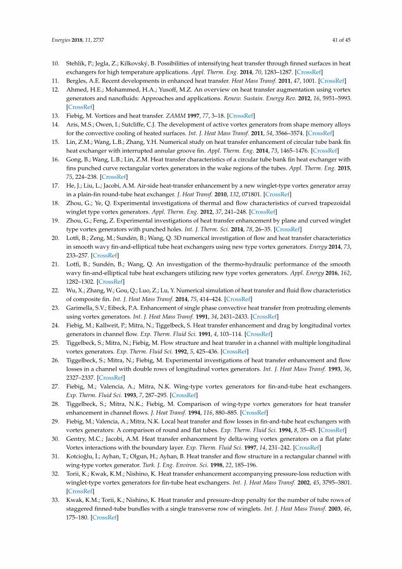
Energies 2018, 11, 2737 41 of 45
10. Stehlík, P.; Jegla, Z.; Kilkovský, B. Possibilities of intensifying heat transfer through finned surfaces in heatexchangers for high temperature applications. Appl. Therm. Eng. 2014, 70, 1283–1287. [CrossRef]
11. Bergles, A.E. Recent developments in enhanced heat transfer. Heat Mass Transf. 2011, 47, 1001. [CrossRef]12. Ahmed, H.E.; Mohammed, H.A.; Yusoff, M.Z. An overview on heat transfer augmentation using vortex
generators and nanofluids: Approaches and applications. Renew. Sustain. Energy Rev. 2012, 16, 5951–5993.[CrossRef]
13. Fiebig, M. Vortices and heat transfer. ZAMM 1997, 77, 3–18. [CrossRef]14. Aris, M.S.; Owen, I.; Sutcliffe, C.J. The development of active vortex generators from shape memory alloys
for the convective cooling of heated surfaces. Int. J. Heat Mass Transf. 2011, 54, 3566–3574. [CrossRef]15. Lin, Z.M.; Wang, L.B.; Zhang, Y.H. Numerical study on heat transfer enhancement of circular tube bank fin
heat exchanger with interrupted annular groove fin. Appl. Therm. Eng. 2014, 73, 1465–1476. [CrossRef]16. Gong, B.; Wang, L.B.; Lin, Z.M. Heat transfer characteristics of a circular tube bank fin heat exchanger with
fins punched curve rectangular vortex generators in the wake regions of the tubes. Appl. Therm. Eng. 2015,75, 224–238. [CrossRef]
17. He, J.; Liu, L.; Jacobi, A.M. Air-side heat-transfer enhancement by a new winglet-type vortex generator arrayin a plain-fin round-tube heat exchanger. J. Heat Transf. 2010, 132, 071801. [CrossRef]
18. Zhou, G.; Ye, Q. Experimental investigations of thermal and flow characteristics of curved trapezoidalwinglet type vortex generators. Appl. Therm. Eng. 2012, 37, 241–248. [CrossRef]
19. Zhou, G.; Feng, Z. Experimental investigations of heat transfer enhancement by plane and curved winglettype vortex generators with punched holes. Int. J. Therm. Sci. 2014, 78, 26–35. [CrossRef]
20. Lotfi, B.; Zeng, M.; Sundén, B.; Wang, Q. 3D numerical investigation of flow and heat transfer characteristicsin smooth wavy fin-and-elliptical tube heat exchangers using new type vortex generators. Energy 2014, 73,233–257. [CrossRef]
21. Lotfi, B.; Sundén, B.; Wang, Q. An investigation of the thermo-hydraulic performance of the smoothwavy fin-and-elliptical tube heat exchangers utilizing new type vortex generators. Appl. Energy 2016, 162,1282–1302. [CrossRef]
22. Wu, X.; Zhang, W.; Gou, Q.; Luo, Z.; Lu, Y. Numerical simulation of heat transfer and fluid flow characteristicsof composite fin. Int. J. Heat Mass Transf. 2014, 75, 414–424. [CrossRef]
23. Garimella, S.V.; Eibeck, P.A. Enhancement of single phase convective heat transfer from protruding elementsusing vortex generators. Int. J. Heat Mass Transf. 1991, 34, 2431–2433. [CrossRef]
24. Fiebig, M.; Kallweit, P.; Mitra, N.; Tiggelbeck, S. Heat transfer enhancement and drag by longitudinal vortexgenerators in channel flow. Exp. Therm. Fluid Sci. 1991, 4, 103–114. [CrossRef]
25. Tiggelbeck, S.; Mitra, N.; Fiebig, M. Flow structure and heat transfer in a channel with multiple longitudinalvortex generators. Exp. Therm. Fluid Sci. 1992, 5, 425–436. [CrossRef]
26. Tiggelbeck, S.; Mitra, N.; Fiebig, M. Experimental investigations of heat transfer enhancement and flowlosses in a channel with double rows of longitudinal vortex generators. Int. J. Heat Mass Transf. 1993, 36,2327–2337. [CrossRef]
27. Fiebig, M.; Valencia, A.; Mitra, N.K. Wing-type vortex generators for fin-and-tube heat exchangers.Exp. Therm. Fluid Sci. 1993, 7, 287–295. [CrossRef]
28. Tiggelbeck, S.; Mitra, N.K.; Fiebig, M. Comparison of wing-type vortex generators for heat transferenhancement in channel flows. J. Heat Transf. 1994, 116, 880–885. [CrossRef]
29. Fiebig, M.; Valencia, A.; Mitra, N.K. Local heat transfer and flow losses in fin-and-tube heat exchangers withvortex generators: A comparison of round and flat tubes. Exp. Therm. Fluid Sci. 1994, 8, 35–45. [CrossRef]
30. Gentry, M.C.; Jacobi, A.M. Heat transfer enhancement by delta-wing vortex generators on a flat plate:Vortex interactions with the boundary layer. Exp. Therm. Fluid Sci. 1997, 14, 231–242. [CrossRef]
31. Kotcioglu, I.; Ayhan, T.; Olgun, H.; Ayhan, B. Heat transfer and flow structure in a rectangular channel withwing-type vortex generator. Turk. J. Eng. Environ. Sci. 1998, 22, 185–196.
32. Torii, K.; Kwak, K.M.; Nishino, K. Heat transfer enhancement accompanying pressure-loss reduction withwinglet-type vortex generators for fin-tube heat exchangers. Int. J. Heat Mass Transf. 2002, 45, 3795–3801.[CrossRef]
33. Kwak, K.M.; Torii, K.; Nishino, K. Heat transfer and pressure-drop penalty for the number of tube rows ofstaggered finned-tube bundles with a single transverse row of winglets. Int. J. Heat Mass Transf. 2003, 46,175–180. [CrossRef]
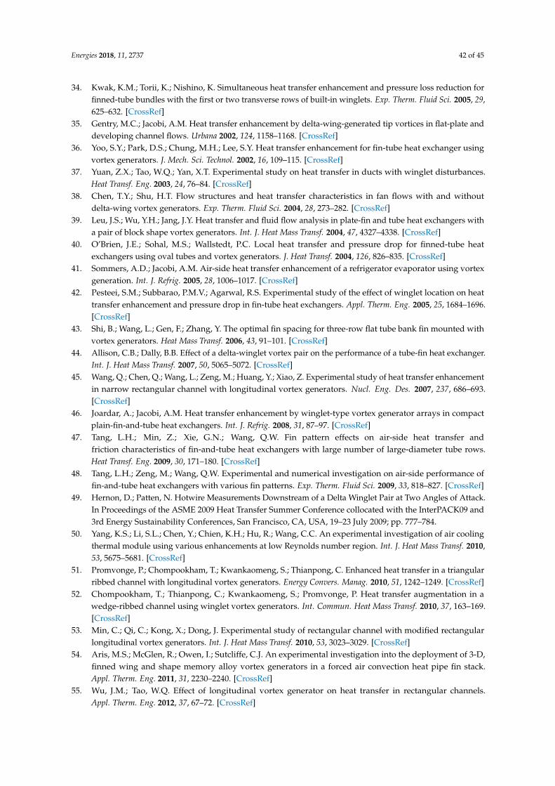
Energies 2018, 11, 2737 42 of 45
34. Kwak, K.M.; Torii, K.; Nishino, K. Simultaneous heat transfer enhancement and pressure loss reduction forfinned-tube bundles with the first or two transverse rows of built-in winglets. Exp. Therm. Fluid Sci. 2005, 29,625–632. [CrossRef]
35. Gentry, M.C.; Jacobi, A.M. Heat transfer enhancement by delta-wing-generated tip vortices in flat-plate anddeveloping channel flows. Urbana 2002, 124, 1158–1168. [CrossRef]
36. Yoo, S.Y.; Park, D.S.; Chung, M.H.; Lee, S.Y. Heat transfer enhancement for fin-tube heat exchanger usingvortex generators. J. Mech. Sci. Technol. 2002, 16, 109–115. [CrossRef]
37. Yuan, Z.X.; Tao, W.Q.; Yan, X.T. Experimental study on heat transfer in ducts with winglet disturbances.Heat Transf. Eng. 2003, 24, 76–84. [CrossRef]
38. Chen, T.Y.; Shu, H.T. Flow structures and heat transfer characteristics in fan flows with and withoutdelta-wing vortex generators. Exp. Therm. Fluid Sci. 2004, 28, 273–282. [CrossRef]
39. Leu, J.S.; Wu, Y.H.; Jang, J.Y. Heat transfer and fluid flow analysis in plate-fin and tube heat exchangers witha pair of block shape vortex generators. Int. J. Heat Mass Transf. 2004, 47, 4327–4338. [CrossRef]
40. O’Brien, J.E.; Sohal, M.S.; Wallstedt, P.C. Local heat transfer and pressure drop for finned-tube heatexchangers using oval tubes and vortex generators. J. Heat Transf. 2004, 126, 826–835. [CrossRef]
41. Sommers, A.D.; Jacobi, A.M. Air-side heat transfer enhancement of a refrigerator evaporator using vortexgeneration. Int. J. Refrig. 2005, 28, 1006–1017. [CrossRef]
42. Pesteei, S.M.; Subbarao, P.M.V.; Agarwal, R.S. Experimental study of the effect of winglet location on heattransfer enhancement and pressure drop in fin-tube heat exchangers. Appl. Therm. Eng. 2005, 25, 1684–1696.[CrossRef]
43. Shi, B.; Wang, L.; Gen, F.; Zhang, Y. The optimal fin spacing for three-row flat tube bank fin mounted withvortex generators. Heat Mass Transf. 2006, 43, 91–101. [CrossRef]
44. Allison, C.B.; Dally, B.B. Effect of a delta-winglet vortex pair on the performance of a tube-fin heat exchanger.Int. J. Heat Mass Transf. 2007, 50, 5065–5072. [CrossRef]
45. Wang, Q.; Chen, Q.; Wang, L.; Zeng, M.; Huang, Y.; Xiao, Z. Experimental study of heat transfer enhancementin narrow rectangular channel with longitudinal vortex generators. Nucl. Eng. Des. 2007, 237, 686–693.[CrossRef]
46. Joardar, A.; Jacobi, A.M. Heat transfer enhancement by winglet-type vortex generator arrays in compactplain-fin-and-tube heat exchangers. Int. J. Refrig. 2008, 31, 87–97. [CrossRef]
47. Tang, L.H.; Min, Z.; Xie, G.N.; Wang, Q.W. Fin pattern effects on air-side heat transfer andfriction characteristics of fin-and-tube heat exchangers with large number of large-diameter tube rows.Heat Transf. Eng. 2009, 30, 171–180. [CrossRef]
48. Tang, L.H.; Zeng, M.; Wang, Q.W. Experimental and numerical investigation on air-side performance offin-and-tube heat exchangers with various fin patterns. Exp. Therm. Fluid Sci. 2009, 33, 818–827. [CrossRef]
49. Hernon, D.; Patten, N. Hotwire Measurements Downstream of a Delta Winglet Pair at Two Angles of Attack.In Proceedings of the ASME 2009 Heat Transfer Summer Conference collocated with the InterPACK09 and3rd Energy Sustainability Conferences, San Francisco, CA, USA, 19–23 July 2009; pp. 777–784.
50. Yang, K.S.; Li, S.L.; Chen, Y.; Chien, K.H.; Hu, R.; Wang, C.C. An experimental investigation of air coolingthermal module using various enhancements at low Reynolds number region. Int. J. Heat Mass Transf. 2010,53, 5675–5681. [CrossRef]
51. Promvonge, P.; Chompookham, T.; Kwankaomeng, S.; Thianpong, C. Enhanced heat transfer in a triangularribbed channel with longitudinal vortex generators. Energy Convers. Manag. 2010, 51, 1242–1249. [CrossRef]
52. Chompookham, T.; Thianpong, C.; Kwankaomeng, S.; Promvonge, P. Heat transfer augmentation in awedge-ribbed channel using winglet vortex generators. Int. Commun. Heat Mass Transf. 2010, 37, 163–169.[CrossRef]
53. Min, C.; Qi, C.; Kong, X.; Dong, J. Experimental study of rectangular channel with modified rectangularlongitudinal vortex generators. Int. J. Heat Mass Transf. 2010, 53, 3023–3029. [CrossRef]
54. Aris, M.S.; McGlen, R.; Owen, I.; Sutcliffe, C.J. An experimental investigation into the deployment of 3-D,finned wing and shape memory alloy vortex generators in a forced air convection heat pipe fin stack.Appl. Therm. Eng. 2011, 31, 2230–2240. [CrossRef]
55. Wu, J.M.; Tao, W.Q. Effect of longitudinal vortex generator on heat transfer in rectangular channels.Appl. Therm. Eng. 2012, 37, 67–72. [CrossRef]
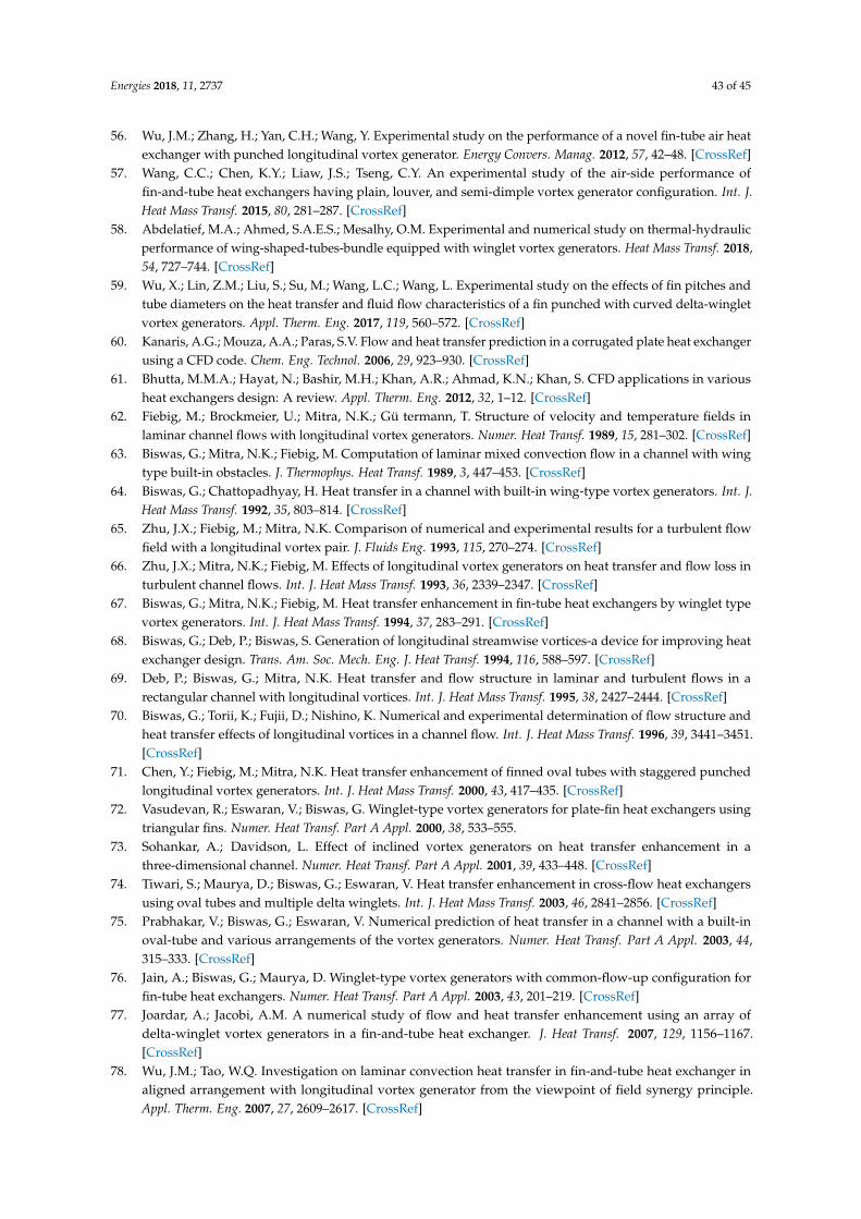
Energies 2018, 11, 2737 43 of 45
56. Wu, J.M.; Zhang, H.; Yan, C.H.; Wang, Y. Experimental study on the performance of a novel fin-tube air heatexchanger with punched longitudinal vortex generator. Energy Convers. Manag. 2012, 57, 42–48. [CrossRef]
57. Wang, C.C.; Chen, K.Y.; Liaw, J.S.; Tseng, C.Y. An experimental study of the air-side performance offin-and-tube heat exchangers having plain, louver, and semi-dimple vortex generator configuration. Int. J.Heat Mass Transf. 2015, 80, 281–287. [CrossRef]
58. Abdelatief, M.A.; Ahmed, S.A.E.S.; Mesalhy, O.M. Experimental and numerical study on thermal-hydraulicperformance of wing-shaped-tubes-bundle equipped with winglet vortex generators. Heat Mass Transf. 2018,54, 727–744. [CrossRef]
59. Wu, X.; Lin, Z.M.; Liu, S.; Su, M.; Wang, L.C.; Wang, L. Experimental study on the effects of fin pitches andtube diameters on the heat transfer and fluid flow characteristics of a fin punched with curved delta-wingletvortex generators. Appl. Therm. Eng. 2017, 119, 560–572. [CrossRef]
60. Kanaris, A.G.; Mouza, A.A.; Paras, S.V. Flow and heat transfer prediction in a corrugated plate heat exchangerusing a CFD code. Chem. Eng. Technol. 2006, 29, 923–930. [CrossRef]
61. Bhutta, M.M.A.; Hayat, N.; Bashir, M.H.; Khan, A.R.; Ahmad, K.N.; Khan, S. CFD applications in variousheat exchangers design: A review. Appl. Therm. Eng. 2012, 32, 1–12. [CrossRef]
62. Fiebig, M.; Brockmeier, U.; Mitra, N.K.; Gü termann, T. Structure of velocity and temperature fields inlaminar channel flows with longitudinal vortex generators. Numer. Heat Transf. 1989, 15, 281–302. [CrossRef]
63. Biswas, G.; Mitra, N.K.; Fiebig, M. Computation of laminar mixed convection flow in a channel with wingtype built-in obstacles. J. Thermophys. Heat Transf. 1989, 3, 447–453. [CrossRef]
64. Biswas, G.; Chattopadhyay, H. Heat transfer in a channel with built-in wing-type vortex generators. Int. J.Heat Mass Transf. 1992, 35, 803–814. [CrossRef]
65. Zhu, J.X.; Fiebig, M.; Mitra, N.K. Comparison of numerical and experimental results for a turbulent flowfield with a longitudinal vortex pair. J. Fluids Eng. 1993, 115, 270–274. [CrossRef]
66. Zhu, J.X.; Mitra, N.K.; Fiebig, M. Effects of longitudinal vortex generators on heat transfer and flow loss inturbulent channel flows. Int. J. Heat Mass Transf. 1993, 36, 2339–2347. [CrossRef]
67. Biswas, G.; Mitra, N.K.; Fiebig, M. Heat transfer enhancement in fin-tube heat exchangers by winglet typevortex generators. Int. J. Heat Mass Transf. 1994, 37, 283–291. [CrossRef]
68. Biswas, G.; Deb, P.; Biswas, S. Generation of longitudinal streamwise vortices-a device for improving heatexchanger design. Trans. Am. Soc. Mech. Eng. J. Heat Transf. 1994, 116, 588–597. [CrossRef]
69. Deb, P.; Biswas, G.; Mitra, N.K. Heat transfer and flow structure in laminar and turbulent flows in arectangular channel with longitudinal vortices. Int. J. Heat Mass Transf. 1995, 38, 2427–2444. [CrossRef]
70. Biswas, G.; Torii, K.; Fujii, D.; Nishino, K. Numerical and experimental determination of flow structure andheat transfer effects of longitudinal vortices in a channel flow. Int. J. Heat Mass Transf. 1996, 39, 3441–3451.[CrossRef]
71. Chen, Y.; Fiebig, M.; Mitra, N.K. Heat transfer enhancement of finned oval tubes with staggered punchedlongitudinal vortex generators. Int. J. Heat Mass Transf. 2000, 43, 417–435. [CrossRef]
72. Vasudevan, R.; Eswaran, V.; Biswas, G. Winglet-type vortex generators for plate-fin heat exchangers usingtriangular fins. Numer. Heat Transf. Part A Appl. 2000, 38, 533–555.
73. Sohankar, A.; Davidson, L. Effect of inclined vortex generators on heat transfer enhancement in athree-dimensional channel. Numer. Heat Transf. Part A Appl. 2001, 39, 433–448. [CrossRef]
74. Tiwari, S.; Maurya, D.; Biswas, G.; Eswaran, V. Heat transfer enhancement in cross-flow heat exchangersusing oval tubes and multiple delta winglets. Int. J. Heat Mass Transf. 2003, 46, 2841–2856. [CrossRef]
75. Prabhakar, V.; Biswas, G.; Eswaran, V. Numerical prediction of heat transfer in a channel with a built-inoval-tube and various arrangements of the vortex generators. Numer. Heat Transf. Part A Appl. 2003, 44,315–333. [CrossRef]
76. Jain, A.; Biswas, G.; Maurya, D. Winglet-type vortex generators with common-flow-up configuration forfin-tube heat exchangers. Numer. Heat Transf. Part A Appl. 2003, 43, 201–219. [CrossRef]
77. Joardar, A.; Jacobi, A.M. A numerical study of flow and heat transfer enhancement using an array ofdelta-winglet vortex generators in a fin-and-tube heat exchanger. J. Heat Transf. 2007, 129, 1156–1167.[CrossRef]
78. Wu, J.M.; Tao, W.Q. Investigation on laminar convection heat transfer in fin-and-tube heat exchanger inaligned arrangement with longitudinal vortex generator from the viewpoint of field synergy principle.Appl. Therm. Eng. 2007, 27, 2609–2617. [CrossRef]
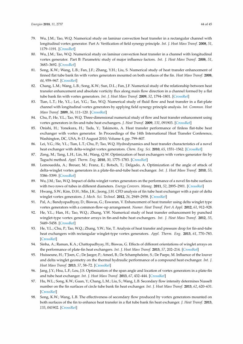
Energies 2018, 11, 2737 44 of 45
79. Wu, J.M.; Tao, W.Q. Numerical study on laminar convection heat transfer in a rectangular channel withlongitudinal vortex generator. Part A: Verification of field synergy principle. Int. J. Heat Mass Transf. 2008, 51,1179–1191. [CrossRef]
80. Wu, J.M.; Tao, W.Q. Numerical study on laminar convection heat transfer in a channel with longitudinalvortex generator. Part B: Parametric study of major influence factors. Int. J. Heat Mass Transf. 2008, 51,3683–3692. [CrossRef]
81. Song, K.W.; Wang, L.B.; Fan, J.F.; Zhang, Y.H.; Liu, S. Numerical study of heat transfer enhancement offinned flat tube bank fin with vortex generators mounted on both surfaces of the fin. Heat Mass Transf. 2008,44, 959–967. [CrossRef]
82. Chang, L.M.; Wang, L.B.; Song, K.W.; Sun, D.L.; Fan, J.F. Numerical study of the relationship between heattransfer enhancement and absolute vorticity flux along main flow direction in a channel formed by a flattube bank fin with vortex generators. Int. J. Heat Mass Transf. 2009, 52, 1794–1801. [CrossRef]
83. Tian, L.T.; He, Y.L.; Lei, Y.G.; Tao, W.Q. Numerical study of fluid flow and heat transfer in a flat-platechannel with longitudinal vortex generators by applying field synergy principle analysis. Int. Commun. HeatMass Transf. 2009, 36, 111–120. [CrossRef]
84. Chu, P.; He, Y.L.; Tao, W.Q. Three-dimensional numerical study of flow and heat transfer enhancement usingvortex generators in fin-and-tube heat exchangers. J. Heat Transf. 2009, 131, 091903. [CrossRef]
85. Onishi, H.; Yonekura, H.; Tada, Y.; Takimoto, A. Heat transfer performance of finless flat-tube heatexchanger with vortex generator. In Proceedings of the 14th International Heat Transfer Conference,Washington, DC, USA, 8–13 August 2010; Volume 4, pp. 799–807.
86. Lei, Y.G.; He, Y.L.; Tian, L.T.; Chu, P.; Tao, W.Q. Hydrodynamics and heat transfer characteristics of a novelheat exchanger with delta-winglet vortex generators. Chem. Eng. Sci. 2010, 65, 1551–1562. [CrossRef]
87. Zeng, M.; Tang, L.H.; Lin, M.; Wang, Q.W. Optimization of heat exchangers with vortex-generator fin byTaguchi method. Appl. Therm. Eng. 2010, 30, 1775–1783. [CrossRef]
88. Lemouedda, A.; Breuer, M.; Franz, E.; Botsch, T.; Delgado, A. Optimization of the angle of attack ofdelta-winglet vortex generators in a plate-fin-and-tube heat exchanger. Int. J. Heat Mass Transf. 2010, 53,5386–5399. [CrossRef]
89. Wu, J.M.; Tao, W.Q. Impact of delta winglet vortex generators on the performance of a novel fin-tube surfaceswith two rows of tubes in different diameters. Energy Convers. Manag. 2011, 52, 2895–2901. [CrossRef]
90. Hwang, S.W.; Kim, D.H.; Min, J.K.; Jeong, J.H. CFD analysis of fin tube heat exchanger with a pair of deltawinglet vortex generators. J. Mech. Sci. Technol. 2012, 26, 2949–2958. [CrossRef]
91. Pal, A.; Bandyopadhyay, D.; Biswas, G.; Eswaran, V. Enhancement of heat transfer using delta winglet typevortex generators with a common-flow-up arrangement. Numer. Heat Transf. Part A Appl. 2012, 61, 912–928.
92. He, Y.L.; Han, H.; Tao, W.Q.; Zhang, Y.W. Numerical study of heat transfer enhancement by punchedwinglet-type vortex generator arrays in fin-and-tube heat exchangers. Int. J. Heat Mass Transf. 2012, 55,5449–5458. [CrossRef]
93. He, Y.L.; Chu, P.; Tao, W.Q.; Zhang, Y.W.; Xie, T. Analysis of heat transfer and pressure drop for fin-and-tubeheat exchangers with rectangular winglet-type vortex generators. Appl. Therm. Eng. 2013, 61, 770–783.[CrossRef]
94. Sinha, A.; Raman, K.A.; Chattopadhyay, H.; Biswas, G. Effects of different orientations of winglet arrays onthe performance of plate-fin heat exchangers. Int. J. Heat Mass Transf. 2013, 57, 202–214. [CrossRef]
95. Huisseune, H.; T’Joen, C.; De Jaeger, P.; Ameel, B.; De Schampheleire, S.; De Paepe, M. Influence of the louverand delta winglet geometry on the thermal hydraulic performance of a compound heat exchanger. Int. J.Heat Mass Transf. 2013, 57, 58–72. [CrossRef]
96. Jang, J.Y.; Hsu, L.F.; Leu, J.S. Optimization of the span angle and location of vortex generators in a plate-finand tube heat exchanger. Int. J. Heat Mass Transf. 2013, 67, 432–444. [CrossRef]
97. Hu, W.L.; Song, K.W.; Guan, Y.; Chang, L.M.; Liu, S.; Wang, L.B. Secondary flow intensity determines Nusseltnumber on the fin surfaces of circle tube bank fin heat exchanger. Int. J. Heat Mass Transf. 2013, 62, 620–631.[CrossRef]
98. Song, K.W.; Wang, L.B. The effectiveness of secondary flow produced by vortex generators mounted onboth surfaces of the fin to enhance heat transfer in a flat tube bank fin heat exchanger. J. Heat Transf. 2013,135, 041902. [CrossRef]
Energies 2018, 11, 2737 45 of 45
99. Saha, P.; Biswas, G.; Sarkar, S. Comparison of winglet-type vortex generators periodically deployed in aplate-fin heat exchanger—A synergy based analysis. Int. J. Heat Mass Transf. 2014, 74, 292–305. [CrossRef]
100. Gholami, A.A.; Wahid, M.A.; Mohammed, H.A. Heat transfer enhancement and pressure drop forfin-and-tube compact heat exchangers with wavy rectangular winglet-type vortex generators. Int. Commun.Heat Mass Transf. 2014, 54, 132–140. [CrossRef]
101. Zhao, X.B.; Tang, G.H.; Ma, X.W.; Tao, W.Q. Numerical investigation of heat transfer and erosioncharacteristics for H-type finned oval-tube with longitudinal vortex generators and dimples. Appl. Energy2014, 127, 93–104. [CrossRef]
102. Lin, Z.M.; Wang, L.B. A multi-domain coupled numerical method for a flat tube bank fin heat exchangerwith delta winglet vortex generators. Numer. Heat Transf. Part A Appl. 2014, 65, 1204–1229. [CrossRef]
103. Behfard, M.; Sohankar, A. Numerical investigation for finding the appropriate design parameters of afin-and-tube heat exchanger with delta winglet vortex generators. Heat Mass Transf. 2016, 52, 21–37.[CrossRef]
104. Lin, Z.M.; Liu, C.P.; Lin, M.; Wang, L.B. Numerical study of flow and heat transfer enhancement of circulartube bank fin heat exchanger with curved delta winglet vortex generators. Appl. Therm. Eng. 2015, 88,198–210. [CrossRef]
105. Sinha, A.; Chattopadhyay, H.; Iyengar, A.K.; Biswas, G. Enhancement of heat transfer in a fin-tube heatexchanger using rectangular winglet type vortex generators. Int. J. Heat Mass Transf. 2016, 101, 667–681.[CrossRef]
106. Oneissi, M.; Habchi, C.; Russeil, S.; Bougeard, D.; Lemenand, T. Novel design of delta winglet pair vortexgenerator for heat transfer enhancement. Int. J. Therm. Sci. 2016, 109, 1–9. [CrossRef]
107. Esmaeilzadeh, A.; Amanifard, N.; Deylami, H.M. Comparison of simple and curved trapezoidal longitudinalvortex generators for optimum flow characteristics and heat transfer augmentation in a heat exchanger.Appl. Therm. Eng. 2017, 125, 1414–1425. [CrossRef]
108. Harlow, F.H.; Welch, J.E. Numerical calculation of time-dependent viscous incompressible flow of fluid withfree surface. Phys. Fluids 1965, 8, 2182–2189. [CrossRef]
109. Hirt, C.W.; Nichols, B.D.; Romero, N.C. SOLA: A Numerical Solution Algorithm for Transient Fluid Flows;Los Alamos Scientific Lab.: Los Alamos, NM, USA, 1975.
110. Cebeci, T.; Shao, J.P.; Kafyeke, F.; Laurendeau, E. Computational Fluid Dynamics for Engineers; Springer:Berlin/Heidelberg, Germany, 2005.
111. Guo, Z.Y.; Li, D.Y.; Wang, B.X. A novel concept for convective heat transfer enhancement. Int. J. HeatMass Transf. 1998, 41, 2221–2225. [CrossRef]
112. Tao, W.Q.; Guo, Z.Y.; Wang, B.X. Field synergy principle for enhancing convective heat transfer—Its extensionand numerical verifications. Int. J. Heat Mass Transf. 2002, 45, 3849–3856. [CrossRef]
113. Tao, W.Q.; He, Y.L.; Wang, Q.W.; Qu, Z.G.; Song, F.Q. A unified analysis on enhancing single phase convectiveheat transfer with field synergy principle. Int. J. Heat Mass Transf. 2002, 45, 4871–4879. [CrossRef]
114. Guo, Z.Y.; Tao, W.Q.; Shah, R.K. The field synergy (coordination) principle and its applications in enhancingsingle phase convective heat transfer. Int. J. Heat Mass Transf. 2005, 48, 1797–1807. [CrossRef]
© 2018 by the authors. Licensee MDPI, Basel, Switzerland. This article is an open accessarticle distributed under the terms and conditions of the Creative Commons Attribution(CC BY) license (http://creativecommons.org/licenses/by/4.0/).