a refreshing 3d view of an ancient sediment collapse and ... · a refreshing 3d view of an ancient...
TRANSCRIPT

A refreshing 3D view of an ancient sediment collapseand slope failure
Veerle A. I. Huvenne1*, Peter F. Croker 2 and Jean-Pierre Henriet1
1Renard Centre of Marine Geology, Krijgslaan 281, S8, 9000 Gent, Belgium; 2Petroleum Affairs Division, Beggars Bush, Haddington Road,
Dublin 4, Ireland
Introduction
Slope failures, submarine landslidesand their morphodynamic expressionson the seafloor have been describedover many years and by severalauthors (e.g.Middleton andHampton,1976; Moore, 1978; Hampton et al.,1996; Mulder and Cochonat, 1996).Their implications for submarine andoffshore structures such as pipelinescan be enormous; a well-known exam-ple is the Grand Banks slide with itsassociated cable breaks (Heezen andEwing, 1952). However, the geologicalconsequences of giant (and smaller)events such as the Storrega Slide(Bugge et al., 1988), are at least asimportant. Hence, the extent and ap-pearance of different kinds of slopefailures have been studied by means ofsidescan sonar imagery, multibeambathymetry, sub-bottom profiling andreflection seismics. Although each ofthese techniques gives a particularinsight into the failure processes, only3D seismics allow a truly holistic studyof the morphology of the feature ofinterest (Hart, 1999). In the presentcontribution, it reveals what looks likea buried slab slide, frozen in time dur-ing the first stages of its development.
Setting
The structure presented herein wasfound in the western part of the
Porcupine Basin, SW Ireland (around52°20¢N, 13°00¢W, Fig. 1). The Por-cupine Basin developed in response tothree major rift phases, associatedwith the opening of the North Atlan-tic Ocean (Masson and Miles, 1986;Croker and Shannon, 1987). Sedi-ments were deposited in pre-rift, syn-rift (Jurassic) and post-rift (Creta-ceous to Tertiary) sequences, creatinga total thickness of up to 10 km. Mostof the Tertiary sediments consist ofdeep marine deposits, although in theEarly Tertiary sequences, deltaic andfan deposits were recognized also(Shannon, 1992). From the Mioceneonwards, sedimentation was domin-ated by drift deposition in whichslumping occurred (Moore and Shan-non, 1991). The Quaternary sedimen-tary history is less well known,although it seems that drift sedimen-tation and current influences haveremained important (McDonnellet al., 1998). Large mound structures(coral banks) are found in three prov-inces on the present-day seabed orburied under the most recent sedimen-tary sequences (Hovland et al., 1994;Henriet et al., 1998). The Magellanprovince, containing mainly buriedmounds, partly overlies the structureof interest here (Fig. 1).
Data
The slope failure described in thispaper was first seen, but not directlyrecognized as such, on high-resolution2D reflection seismic data acquired in1997 and 1999. However, the subse-quent seismic analysis of the upper400 ms of an industrial 3D seismic
data volume (provided in 1999 byStatoil Exploration (Ireland) Ltd. andits partners) allowed the interpretationto be completed.The 2D single channel sparker
(200–3000 Hz) and watergun (80–300 Hz) data have a penetration depthof some 350 m and a resolution of1–2 ms. The 3D data were shot withairgun arrays; the horizontal resolu-tion is 12.5 · 12.5 m, the verticalresolution 4 ms, and the total datasetcovers 1040 km2. 2D and 3D inter-pretations were integrated in order toidentify those key reflections thatwould best describe the morphologyof the area and the feature (see Fig. 2):the seafloor (light blue), the reflectionmarking the base of the buriedmounds (yellow), the unconformitylying over the slope failure (TSunconformity, green), and the slideplane of this slope failure (dark blue).Based on an industrial site surveycarried out in the Magellan province(Britsurvey, 1997), the moundbasereflection is dated as ‘near base Qua-ternary’, while the underlying slide isof late Pliocene age. In- and cross-lines, time and horizon slices wereanalysed; gradient and aspect mapswere calculated and studied within aGIS-environment based on GoldenSoftware and Geographix softwarepackages.
A buried collapse
The deformation feature describedhere is located at a depth of 775–1265 ms TWT, and is covered by asediment drape of some 200–220 msTWT. Its base is formed by one
ABSTRACT
The combined analysis of high-resolution 2D seismics and anindustrial 3D seismic data volume from the western PorcupineBasin, offshore SW Ireland, revealed an unusual picture of aburied sediment collapse and slope failure. A proportionallythin (£ 85 m) but vast (> 750 km2) slab of consolidatedsediments started to slide downslope, in the meantime break-ing into hundreds of vertically undisturbed blocks, up to 500 m
in diameter. The most probably overpressured underlyinghorizon seems to have liquefied and acted as a slide planeuntil the excess pore pressure had dissipated. Then – still veryearly in the slide development – the process stopped, freezingthe failure at its initial stage.
Terra Nova, 14, 33–40, 2002
*Correspondence: V. A. I. Huvenne,
Renard Centre of Marine Geology, Krijgs-
laan 281, S8, 9000 Gent, Belgium. Tel.:
+32 9 264 4584; fax: +32 9 264 4967;
e-mail: [email protected]
Ó 2002 Blackwell Science Ltd 33

continuous reflection, subparallel tothe underlying sequences, dippinggently (0.5°) to the SE. The top bound-ary is an unconformity that has beencovered by an onlapping sequence ofpostdeformational sediments (Fig. 2).The feature itself has a chaotic facieswith discontinuous reflections. It hasa sharp downdip termination, andwedges out updip towards a smallscarp in the TS unconformity.
Fig. 1 Location map of the study area. The contour interval in both figures is 100 m.
WE
5 k
m
0.9
00
0.9
00
0.8
00
0.8
00
0.7
00
0.7
00
1.1
00
1.1
00
1.2
00
1.2
00
1.3
00
1.3
00
1.0
00
1.0
00
TSUnco
nform
ity
Slideplane
Sea
floor
Base
ofmounds
Fig.3
headwallscarp
Slidetoe
TWT (s)
Fig. 2 Inline 2158 (0.6–1.3 s) runningNW–SE through the 3D data volume.The identified reflections are indicated indifferent colours. The buried moundsand moats of the Magellan MoundProvince are observed above the chaoticfacies of the slide. The reflection indica-ted in red illustrates their morphology.A possible link between the mounds andthe slope failure is not proven yet.
3D view of an ancient sediment collapse/slope failure • V. A. I. Huvenne et al. Terra Nova, Vol 14, No. 1, 33–40.............................................................................................................................................................
34 Ó 2002 Blackwell Science Ltd

The best overview of the horizontalstructure of the feature is obtainedfrom a horizon amplitude map. InFig. 3 the downslope part of thefeature is presented in this way. Itclearly shows the downdip termin-ation, forming a frontal bulge withapparent compressional ridges.This set of observations allows the
first interpretation of this feature as aburied slope failure, with a small butsignificant headwall scarp and animpressive toe.
Headwall and toe
The location of the headwall scarpwas derived from the gradient map ofthe picked TS unconformity (Fig. 4).Its length (on the 3D map) is » 19 km,
its strike is more or less NE–SW(35°N), and its height varies betweena few to 25 m.The failed slab itself has a maxi-
mum thickness of some 85 m at itsdistal end, on average some 30 kmfurther downslope from the headwallscarp, and wedges out upslope on thedetachment plane. Part of this thick-ness change has a stratigraphic char-acter, coherent with the normalsedimentary thickness change on theslope. Part of it however, is the resultof compressional dynamics in the toeof the failure.This toe could also be identified on
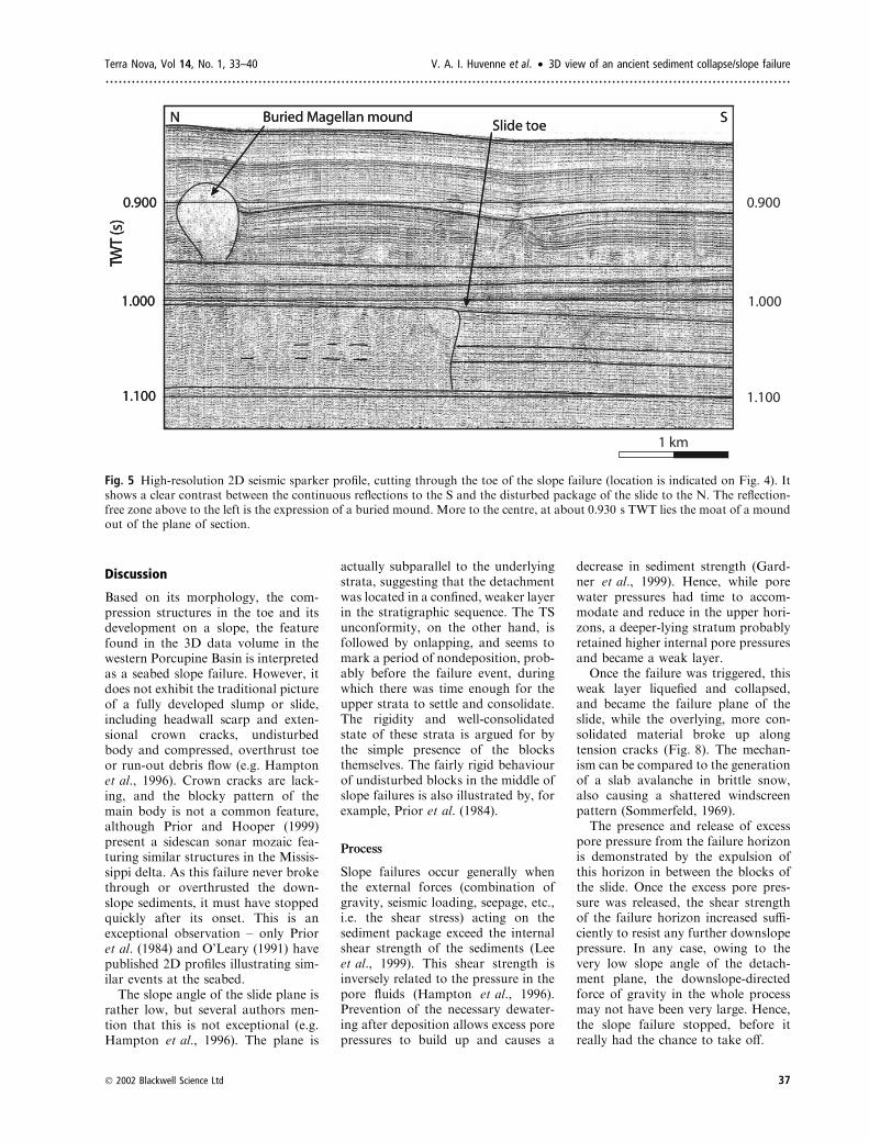
several of the 2D seismic lines adja-cent to the 3D volume (Figs 4 and 5).This suggests that the feature could benearly twice as large as the part seen
on the 3D data, which is estimated tobe » 750 km2. The headwall scarpcould not be identified on any of thehigh-resolution 2D seismics, and mostprobably lies beyond the extent of thisdataset.
Blocky pattern
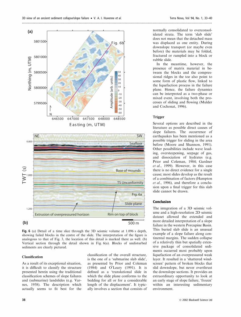
The most striking feature of this slopefailure, however, is the blocky pattern,which looks like a shattered wind-screen on the horizon amplitude map(Fig. 3). Some of the blocks measuremore than 500 m in diameter, whilethe average size is » 200 m. Theirsharp edges are in clear contrast withthe surrounding chaotic matrix(Fig. 6). They consist of undisturbedsediments, which kept the original
636000 641000 646000 651000Easting(m, UTM)
5788000
5793000
5798000
5803000
Northing(m, UTM)
N
Fig. 7a
Fig. 6a
Am
plit
ud
e (a
rb. u
nit
s)
-70
-60
-50
-40
-30
-20
-10
0
10
20
30
40
50
60
70
5 km
Fig. 3 Amplitude map of part of the TS horizon, shifted downwards by 43 ms. Surface is indicated in black in Fig. 2. Detailshowing toe and blocky part of the slope failure. For the location of this detail, see Fig. 4.
Terra Nova, Vol 14, No. 1, 33–40 V. A. I. Huvenne et al. • 3D view of an ancient sediment collapse/slope failure.............................................................................................................................................................
Ó 2002 Blackwell Science Ltd 35

stratification over the whole thicknessof the slope failure, and they aregenerally not tilted, but instead areslightly tapered upwards (Fig. 6b).Amplitude analysis shows enhanced
absolute amplitudes on the edges,especially in the upper strata. Someof these upper reflections also appearto be bent upwards, creating a rim onthe top of the sediment blocks. Thesesignatures could be the consequenceof slight compression, although thereis no obvious sign of shear betweenthe blocks in the body of the failure.They also could be linked withupward flow. In some places the basalreflections under the blocks show
small upward bulges between theblocks. Apart from this effect, thematrix between the blocks is largelychaotic.Compared to the rest of the failure,
the internal structure of the frontalbulge is strikingly different. The blocksare more elongate and squeezed intopressure ridges (Fig. 7a), while theinternal structure of the sequence ismore disturbed (Fig. 7b). Some blocksseem to be tilted and thrusted, andany internal stratification has mostlydisappeared. However, the collapsedsediments do not seem to have over-thrust the downslope undisturbed se-quences. No ‘runout’ of the slope
failure seems to have occurred, al-though the sediment blocks clearlyare compressed in the toe. The effectis clear on 3D sections, but thecontrast between slide and undis-turbed strata is even sharper on 2Dprofiles (Fig. 5). The details of blocksand irregular matrix, however, aremore difficult to interpret in 2D view.Another remarkable fact is that allindications for compressional stressare concentrated in the toe of theslide: except for some slightly en-hanced amplitudes on certain 3Dsections, no effects relating to in-creased stresses are present in thesequences further downslope.
610000 620000 630000 640000 650000 660000
Easting (m, UTM)
5770000
5780000
5790000
5800000
5810000
5820000
Nor
thin
g (m
, UTM
)
0
1
2
3
4
5
6
7
8
9
10 Headwall scarp
N
Slide toe
Gra
dien
t (ar
b. u
nits
)
Fig. 3
Fig. 2
10 km
Fig. 5
Fig. 4 Gradient map of the picked TS unconformity time structure map. Gradients are in arbitrary units as they are calculatedfrom time rather than from depth information directly. Diamonds indicate locations of the slide toe, identified on 2D seismic lines.
3D view of an ancient sediment collapse/slope failure • V. A. I. Huvenne et al. Terra Nova, Vol 14, No. 1, 33–40.............................................................................................................................................................
36 Ó 2002 Blackwell Science Ltd
Discussion
Based on its morphology, the com-pression structures in the toe and itsdevelopment on a slope, the featurefound in the 3D data volume in thewestern Porcupine Basin is interpretedas a seabed slope failure. However, itdoes not exhibit the traditional pictureof a fully developed slump or slide,including headwall scarp and exten-sional crown cracks, undisturbedbody and compressed, overthrust toeor run-out debris flow (e.g. Hamptonet al., 1996). Crown cracks are lack-ing, and the blocky pattern of themain body is not a common feature,although Prior and Hooper (1999)present a sidescan sonar mozaic fea-turing similar structures in the Missis-sippi delta. As this failure never brokethrough or overthrusted the down-slope sediments, it must have stoppedquickly after its onset. This is anexceptional observation – only Prioret al. (1984) and O’Leary (1991) havepublished 2D profiles illustrating sim-ilar events at the seabed.The slope angle of the slide plane is
rather low, but several authors men-tion that this is not exceptional (e.g.Hampton et al., 1996). The plane is
actually subparallel to the underlyingstrata, suggesting that the detachmentwas located in a confined, weaker layerin the stratigraphic sequence. The TSunconformity, on the other hand, isfollowed by onlapping, and seems tomark a period of nondeposition, prob-ably before the failure event, duringwhich there was time enough for theupper strata to settle and consolidate.The rigidity and well-consolidatedstate of these strata is argued for bythe simple presence of the blocksthemselves. The fairly rigid behaviourof undisturbed blocks in the middle ofslope failures is also illustrated by, forexample, Prior et al. (1984).
Process
Slope failures occur generally whenthe external forces (combination ofgravity, seismic loading, seepage, etc.,i.e. the shear stress) acting on thesediment package exceed the internalshear strength of the sediments (Leeet al., 1999). This shear strength isinversely related to the pressure in thepore fluids (Hampton et al., 1996).Prevention of the necessary dewater-ing after deposition allows excess porepressures to build up and causes a
decrease in sediment strength (Gard-ner et al., 1999). Hence, while porewater pressures had time to accom-modate and reduce in the upper hori-zons, a deeper-lying stratum probablyretained higher internal pore pressuresand became a weak layer.Once the failure was triggered, this
weak layer liquefied and collapsed,and became the failure plane of theslide, while the overlying, more con-solidated material broke up alongtension cracks (Fig. 8). The mechan-ism can be compared to the generationof a slab avalanche in brittle snow,also causing a shattered windscreenpattern (Sommerfeld, 1969).The presence and release of excess
pore pressure from the failure horizonis demonstrated by the expulsion ofthis horizon in between the blocks ofthe slide. Once the excess pore pres-sure was released, the shear strengthof the failure horizon increased suffi-ciently to resist any further downslopepressure. In any case, owing to thevery low slope angle of the detach-ment plane, the downslope-directedforce of gravity in the whole processmay not have been very large. Hence,the slope failure stopped, before itreally had the chance to take off.
Fig. 5 High-resolution 2D seismic sparker profile, cutting through the toe of the slope failure (location is indicated on Fig. 4). Itshows a clear contrast between the continuous reflections to the S and the disturbed package of the slide to the N. The reflection-free zone above to the left is the expression of a buried mound. More to the centre, at about 0.930 s TWT lies the moat of a moundout of the plane of section.
Terra Nova, Vol 14, No. 1, 33–40 V. A. I. Huvenne et al. • 3D view of an ancient sediment collapse/slope failure.............................................................................................................................................................
Ó 2002 Blackwell Science Ltd 37
Classification
As a result of its exceptional situation,it is difficult to classify the structurepresented herein using the traditionalclassification schemes of slope failuresand (submarine) landslides (e.g. Var-nes, 1958). The description whichactually seems to fit best for the
classification of the overall structure,is the one of a ‘submarine slab slide’,as presented by Prior and Coleman(1984) and O’Leary (1991). It isdefined as a ‘translational slide inwhich the slide plane conforms to thebedding for all or for a considerablelength of the displacement’. It typic-ally involves a section that consists of
normally consolidated to overconsol-idated strata. The term ‘slab slide’does not mean that the detached masswas displaced as one entity. Duringdownslope transport (or maybe evenbefore) the materials may be folded,fractured or rumpled into a block orrubble slide.In the meantime, however, the
presence of matrix material in be-tween the blocks and the compres-sional ridges in the toe also point tosome form of plastic flow, linked tothe liquefaction process in the failureplane. Hence, the failure dynamicscan be interpreted as a two-phase ormixed event, involving both the pro-cesses of sliding and flowing (Mulderand Cochonat, 1996).
Trigger
Several options are described in theliterature as possible direct causes ofslope failures. The occurrence ofearthquakes has been mentioned as apossible trigger for sliding in the areabefore (Moore and Shannon, 1991).Other possibilities include wave load-ing, oversteepening, seepage of gas,and dissociation of hydrates (e.g.Prior and Coleman, 1984; Gardneret al., 1999). However, in this casethere is no direct evidence for a singlecause; most slides develop as the resultof a combination of factors (Hamptonet al., 1996), and therefore a conclu-sion upon a final trigger for this slabslide cannot be drawn.
Conclusion
The integration of a 3D seismic vol-ume and a high-resolution 2D seismicdataset allowed the extended andmore detailed interpretation of a slopefailure in the western Porcupine Basin.This buried slab slide is an unusualexample of a slope failure along con-tinental margins. The sudden collapseof a relatively thin but spatially exten-sive package of consolidated sedi-ments occurred most probably uponliquefaction of an overpressured weaklayer. It resulted in a ‘shattered wind-screen’ pattern of broken blocks thatslid downslope, but never overthrustthe downslope sections. It provides anextraordinary opportunity to look atan early stage of slope failure, ‘frozen’within an interesting sedimentaryenvironment.
(a)
(b)
Fig. 6 (a) Detail of a time slice through the 3D seismic volume at 1.096 s depth,showing failed blocks in the centre of the slide. The interpretation of the figure isanalogous to that of Fig. 3, the location of this detail is marked there as well. (b)Vertical section through the detail shown in Fig. 6(a). Blocks of undisturbedsediments are clearly pictured.
3D view of an ancient sediment collapse/slope failure • V. A. I. Huvenne et al. Terra Nova, Vol 14, No. 1, 33–40.............................................................................................................................................................
38 Ó 2002 Blackwell Science Ltd

Acknowledgments
The authors are very grateful to StatoilExploration (Ireland) Ltd, its partnersConoco (U.K.) Ltd, Enterprise EnergyIreland Ltd. and Dana Petroleum plc, andChevron U.K. Ltd for the provision of andpermission to use the 3D seismic dataset.Thanks also to the scientific party and thecrew of the RV Belgica for the collection ofthe 2D seismic data. Ben De Mol andPieter Van Rensbergen checked the manu-script at an early stage. This research islinked to the EU projects GEOMOUNDand ECOMOUND (5th Framework Pro-gram) and is funded by the concertedaction ‘Porcupine-Belgica’ (BOF, Univer-sity of Ghent). Veerle Huvenne is fundedthrough a grant of the FWO, Flanders(‘Aspirant’).
References
BRITSURVEY, 1997. Total Oil Marineplc, site survey Irish Block 35/17-1, 14/11/96–13/12/96, final report.Report releasedby Petroleum Affairs Division, Dublin.
Bugge, T., Belderson, R.H. and Kenyon,N.H., 1988. The Storrega Slide. Phil.Trans. R. Soc. A, 325, 357–388.
Croker, P.F. and Shannon, P.M., 1987.The evolution and hydrocarbon pros-pectivity of the Porcupine Basin, Off-shore Ireland. In: Petroleum Geology ofNorth West Europe (J. Brooks and K.W.Glennie, eds), Vol. 2, pp. 633–642.Graham and Trotman, London.
Gardner, J.V., Prior, D.B. and Field, M.E.,1999. Humboldt Slide – a large shear-dominated retrogressive slope failure.Mar. Geol., 154, 323–338.
Hampton, M.A., Lee, H.J. and Locat, J.,1996. Submarine landslides. Rev. Geo-phys. 34, 33–59.
Hart, B.S., 1999. Definition of subsurfacestratigraphy, structure and rock proper-ties from 3-D seismic data. Earth-Sci.Rev., 47, 189–218.
Heezen, B.C. and Ewing, M., 1952. Tur-bidity currents and submarine slumps,and the 1929 Grand Banks earthquake.Am. J. Sci., 250, 849–873.
Henriet, J.P., De Mol, B., Pillen, S. et al.,1998. Gas hydrate crystals may helpbuild reefs. Nature, 391, 648–649.
Hovland, M., Croker, P.F. and Martin,M., 1994. Fault-associated seabed
(a)
(b)
Fig. 7 (a) Detail of a time-slice throughthe 3D seismic volume at 1.148 s depth,showing failed blocks in the toe of theslide. The location of the detail ismarked in Fig. 3. (b) Vertical sectionthrough the detail shown in Fig. 7(a).Blocks are smaller than in the centre,and slightly tilted.
Terra Nova, Vol 14, No. 1, 33–40 V. A. I. Huvenne et al. • 3D view of an ancient sediment collapse/slope failure.............................................................................................................................................................
Ó 2002 Blackwell Science Ltd 39

mounds (carbonate knolls?) off westernIreland and north-west Australia. Mar.Petrol. Geol., 11, 232–246.
Lee, H., Locat, J., Dartnell, P., Israel, K.and Wong, F., 1999. Regional variabilityof slope stability: application to the Eel
margin, California. Mar. Geol., 154,305–321.
Masson, D.G. and Miles, P.R., 1986.Structure and development of PorcupineSeabight sedimentary basin, offshoresouthwest Ireland. Bull. Am. Ass. Petrol.Geol., 70, 536–548.
McDonnell, A., Krylov, O. and Limonov,A., 1998. Seismic profiling data. In: ColdWater Carbonate Mounds and SedimentTransport on the Northeast AtlanticMargin (N.H. Kenyon et al., eds),IOC Technical Series 52, pp. 25–33.UNESCO, Paris.
Middleton, G.V. and Hampton, M.A.,1976. Subaqueous sediment transportand deposition by sediment gravity flows.In: Marine Sediment Transport and En-vironmental Management (D.J. Stanley,and D.J.P. Swift, eds), pp. 197–218. JohnWiley and Sons, New York.
Moore, D.G., 1978. Submarine slides.In: Rockslides and Avalanches(B. Voight, ed.), pp. 563–604. Elsevier,Oxford.
Moore, J.G. and Shannon, P.M., 1991.Slump structures in the Late Tertiary ofthe Porcupine Basin, offshore Ireland.Mar. Petrol. Geol., 8, 184–197.
Mulder, R. and Cochonat, P., 1996. Clas-sification of offshore mass movements.J. Sediment. Res., 66, 43–57.
O’Leary, D.W., 1991. Structures and mor-phology of submarine slab slides: cluesto origin and behavior. Mar. Geotech-nol., 10, 53–69.
Prior, D.B. and Coleman, J.M., 1984.Submarine slope instability. In: SlopeInstability (D. Brunsden and D.B. Prior,eds), pp. 419–455. Wiley, New York.
Prior, D.B. and Hooper, J.R., 1999. Seafloor engineering geomorphology: recentachievements and future directions.Geomorphology, 31, 411–439.
Prior, D.B., Bornhold, B.D. and Johns,M.W., 1984. Depositional characteristicsof a submarine debris flow. J. Geol., 92,707–727.
Shannon, P.M., 1992. Early Tertiary sub-marine fan deposits in the PorcupineBasin, offshore Ireland. In: Basins on theAtlantic Seaboard: Petroleum Geology,Sedimentology and Basin Evolution(J. Parnell,, ed.). Spec. Publ. Geol. Soc.London, 62, 351–373.
Sommerfeld, R.A., 1969. The role of stressconcentration in slab avalanche release.J. Glaciol., 8, 451–462.
Varnes, D.J., 1958. Landslide types andprocesses. In: Landslides and EngineeringPractice (E.B. Eckel, ed.), HighwayResearch Board special report 29, U.S.National Research Council publication544, pp. 20–47. US National ResearchCouncil, Washington, DC.
Received 10 March 2001; revised versionaccepted 12 November 2001
Fig. 8 Schematic presentation of the sliding process: (a) initial, subparallel stratifiedsediment sequence, probably oveconsolidated in the upper strata; (b) first stage aftertriggering: failure along the headwall scarp and along the subhorizontal, weak,overpressured layer. Development of tension cracks in the sediment slab; (c) as thesediment slab slides down, the interaction of the tension cracks results in thedevelopment of the blocky pattern. The weak layer liquefies, the overpressure isaccomodated by the release of excess fluids and excess pore pressure between theblocks, creating the chaotic matrix. Compression takes place in the toe part of theslide. The Porcupine/Magellan slide stopped its development here. (d) Hypotheticalfurther development stage of the slide (one of the several possibilities if the failure hadnot frozen as it did): overthrusting of sliding material over the downslope sedimentpackages; development of a debris flow, probably still carrying a few remainingblocks of undisturbed sediments.
3D view of an ancient sediment collapse/slope failure • V. A. I. Huvenne et al. Terra Nova, Vol 14, No. 1, 33–40.............................................................................................................................................................
40 Ó 2002 Blackwell Science Ltd