a real-time, event based driver alert system for …€¦ · technology demands technology-wise its...
TRANSCRIPT
A REAL-TIME, EVENT BASED DRIVER ALERT SYSTEM FOR ACCIDENT
AVOIDANCE DUE TO RED LIGHT RUNNING
By
Deepti Thopte
Thesis
Submitted to the Faculty of the
Graduate School of Vanderbilt University
in partial fulfillment of the requirements
for the degree of
MASTER OF SCIENCE
in
Computer Science
August, 2009
Nashville, Tennessee
Approved by:
Dr. Aniruddha Gokhale
Dr. Jules White
To my family for their immense love and support
And
Varun for believing in me

ACKNOWLEDGEMENTS
I would first of all like to thank Prof. Aniruddha Gokhale for showing faith in my
abilities throughout my stay at Vanderbilt. His research thought process and teaching
skills always influenced me. I would also like to thank Dr. Jules White for his useful
comments and support for my thesis.
I would like to thank Dr Roth, Dr Dowdy, Dr Schmidt for their support and
encouragement during the course of working as a TA. I also thank Vanderbilt School of
Engineering for supporting me through the course of my Masters education.
I would like to thank my beloved Aaji, Shruti, Tai, Harshal, Baba and Aai for their love,
support and encouragement and Varun for always being there. I also thank Jui for her
constant support and Aparna for giving me strength.
I would like to thank all my friends Tina, Saumitra, Tripti, Aditya, Rajan, Chetan, Pooja
and Satabdi for their wonderful company and friendship.
Last but not least I am very grateful for having my wonderful parents Aai and Dada who
have always shown me the right path and have always encouraged me to do the right
thing. Their struggle in life is awe inspiring and motivating for me to keep going on.
TABLE OF CONTENTS
Page
DEDICATION ............................................................................................................. iii
ACKNOWLEDGEMENTS .......................................................................................... v
LIST OF FIGURES ................................................................................................... viii Chapter
I. INTRODUCTION .................................................................................................. 1
Background ......................................................................................................... 1
Intelligent Transport Systems (ITS) ................................................................ 1
The Problem .................................................................................................... 2
Our Solution - The Intelligent Traffic Light System....................................... 3
ITS Challenges .................................................................................................... 4
Technology demands....................................................................................... 4
Vehicular Adhoc Networks (VANETs) .......................................................... 5
Publish Subscribe Technology ............................................................................ 6
Importance of Pub/Sub .................................................................................... 6
Vehicular Communication .................................................................................. 7
Types of Vehicular Communication ............................................................... 7
Our Communication Choice ........................................................................... 8
Thesis Organization......................................................................................... 8
II. THE INTELLIGENT TRAFFIC LIGHT SYSTEM ............................................ 10
Motivation ..................................................................................................... 10
Problem to be addressed ............................................................................ 10
ITL Components ........................................................................................... 11
Traffic Light .............................................................................................. 11
Road Side Units (RSUs) ............................................................................ 12
Vehicle ...................................................................................................... 13
ITL Considerations ........................................................................................ 13
Types of Traffic Signals ............................................................................ 13
Making a choice ........................................................................................ 14
ITL Architecture ............................................................................................ 15
Typical execution cycle in the system....................................................... 15
Summary of event flow ............................................................................. 17
Need for RSUs .......................................................................................... 18
Estimating safe stopping distance and deceleration for vehicles .................. 18
Background ............................................................................................... 18
Safety Distance Calculation ...................................................................... 20
Coefficient of friction under varied road conditions ................................. 22
Optimal Placement of RSUs ......................................................................... 22
RSU placement problem ........................................................................... 22
RSU placement solution ............................................................................ 22
Publish Subscribe Paradigm in ITL .......................................................... 23
III. SIMULATION .................................................................................................... 25
Omnet++/INET ............................................................................................. 25
Introduction ............................................................................................... 25
Modules Used ................................................................................................ 26
Channel Control ........................................................................................ 26
FlatNetworkConfigurator .......................................................................... 27
RSU (Road-Side-Unit)/ITL Structure (Wireless Host) ............................. 28
MFMobileHost .......................................................................................... 29
Router ........................................................................................................ 30
Simulation Study ........................................................................................... 31
Simulation Results..................................................................................... 31
IV FUTURE ENHANCEMENTS AND CONCLUSION ........................................ 35
Future Enhancements and Conclusion .......................................................... 35
Conclusion ................................................................................................. 35
Future Enhancements ................................................................................ 35
REFERENCES ................................................................................................ 37
LIST OF FIGURES
Page
Figure i : Collision warning application ............................................................................. 1
Figure ii : Traffic monitoring and Congestion Control ....................................................... 1
Figure iii : Red Light Running ............................................................................................ 2
Figure iv : VANETs ............................................................................................................ 5
Figure v : Publish Subscribe Technology .......................................................................... 6
Figure vi : The Intelligent Traffic Light System ............................................................... 11
Figure vii : Road Side Unit ............................................................................................... 12
Figure viii : Vehicle........................................................................................................... 13
Figure ix : Fleet Recognition ............................................................................................. 15
Figure x : Event Flow in ITL ............................................................................................ 17
Figure xi : Sample RSU Network Application.................................................................. 18
Figure xii : Safety Distance Calculation ........................................................................... 20
Figure xiii : RSU / ITL Architecture ................................................................................. 28
Figure xiv : Vehicle Architecture ...................................................................................... 29
Figure xv : Router ............................................................................................................. 30
Figure xvi : Omnet++ Simulation ..................................................................................... 31
Figure xvii : Components seen during simulation ............................................................ 33
Figure xviii : Event Log of the simulation ........................................................................ 34
1
CHAPTER I
INTRODUCTION
Background
Intelligent Transport Systems (ITS)
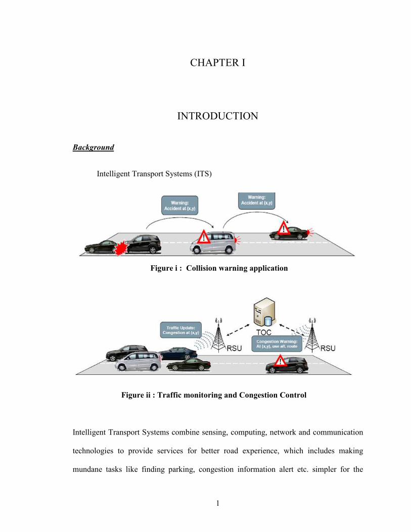
Intelligent Transport Systems combine sensing, computing, network and communication
technologies to provide services for better road experience, which includes making
mundane tasks like finding parking, congestion information alert etc. simpler for the
Figure i : Collision warning application
Figure ii : Traffic monitoring and Congestion Control
2
driver. Vehicular Adhoc Networks (VANETS) are networks, in which vehicles equipped
with short-range radio sense, collect and disseminate information to other interested
vehicles forming an ad hoc network of Vehicles. Vehicles can also communicate with
Road Side Units (RSU) and in our case applications like The Intelligent Traffic Light
System (ITL) that form a hybrid wired and wireless infrastructure. A plethora of
applications have emerged in this domain: safety related applications like accident
warning, cooperative collision detection, traffic management applications like congestion
control, better route detection, fun driving applications like gaming, chatting or
multimedia streaming, travelers information applications like pre-trip planners,
automated parking spot assignment and many more. The benefits of such applications are
immense, improved efficiency, reduction in accidents, injuries and fatality rates, better
response system, reduced congestion, reduced pollution, reduced costs, reduced fuel
consumption and many more.
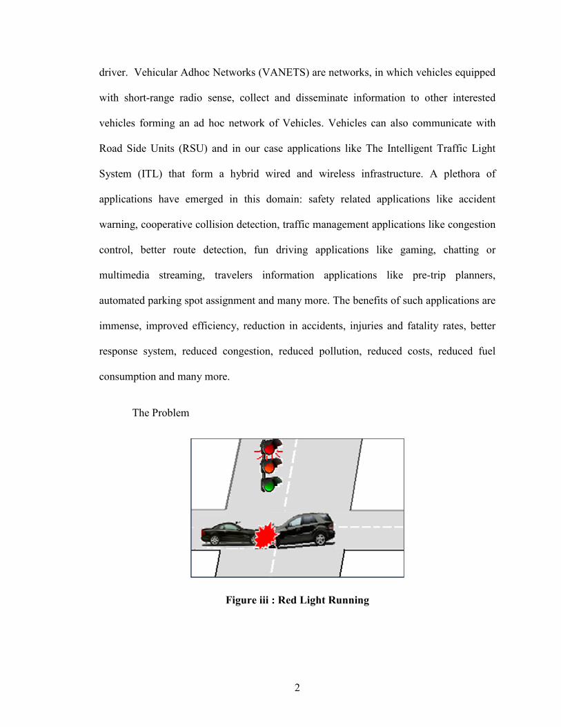
The Problem
Figure iii : Red Light Running
3
Road safety has always been an important aspect addressed by ITS. Traffic signals
provide the key mechanism to regulate traffic, and promote safe and efficient traffic flow
at intersections. However, incidents of red light running can compromise the safety of the
system. Research shows that many drivers violate red signals, placing themselves and
other road users at risk for serious collisions. These incidents stem mostly due to the well
known dilemma zone problem where the drivers cannot decide whether slowing down
the vehicle would bring their vehicle to a stop or should they increase the speed and cross
the intersection. Other factors, such as wet road conditions, make the problem worse.
Thus, new techniques are needed to assist drivers in taking a well-informed decision
about when they should start decelerating in order to come to a halt at the traffic light.
Our Solution - The Intelligent Traffic Light System
The Intelligent Traffic Light System (ITL) is a cyber physical application that combines
information technology (e.g., real-time publish/subscribe semantics) and communications
technology (e.g., mobility and wireless) with the transportation infrastructure (e.g.,
vehicles, traffic lights and road-side units) to address red light running incidents. ITL
aims at timely, reliable warning message dissemination in order to avoid running the red
light. ITL behaves as the publisher and vehicles subscribe to warning messages published
for them. ITL estimates when a traffic light will change to red, and warns drivers of
approaching vehicles about when and how much to slow down to avoid red light running.
ITL can account for road conditions, which increases its usability in challenging weather
conditions.
4
ITS Challenges
Technology demands
Technology-wise ITS applications are very demanding. They need real-time, scalable and
reliable delivery of information. Many ITS applications have very strict time constraints.
Like in case of ITL driver won’t be interested in any traffic light warning received after a
certain time frame or any collision warning after he himself visualizes the situation.
Scalability becomes critical because there can be very different technologies and many
vehicles (can reach over 100) involved on the road. Reliable dissemination as well as
priority based service is required for many ITS applications to become useful. Need for
prioritization can be emphasized by example of messages involving collision warning in
route of the vehicle and traffic congestion in other part in the route. First one should take
precedence over the other. Also, accident notification information needs to be
disseminated to security people as fast as possible, thus timely dissemination is
important.
5
Vehicular Adhoc Networks (VANETs)
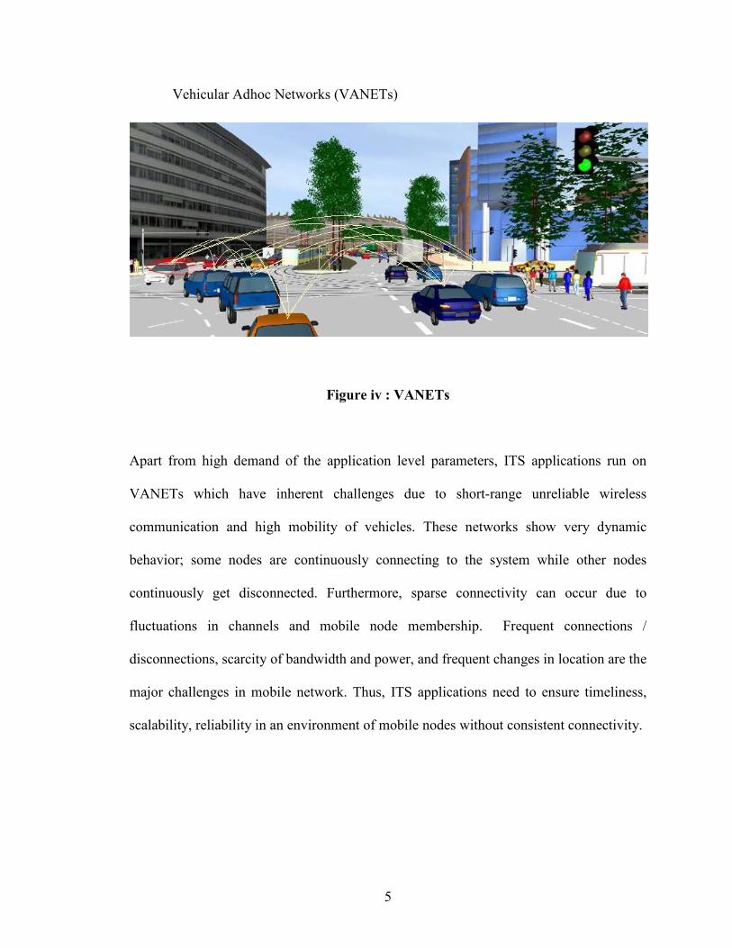
Figure iv : VANETs
Apart from high demand of the application level parameters, ITS applications run on
VANETs which have inherent challenges due to short-range unreliable wireless
communication and high mobility of vehicles. These networks show very dynamic
behavior; some nodes are continuously connecting to the system while other nodes
continuously get disconnected. Furthermore, sparse connectivity can occur due to
fluctuations in channels and mobile node membership. Frequent connections /
disconnections, scarcity of bandwidth and power, and frequent changes in location are the
major challenges in mobile network. Thus, ITS applications need to ensure timeliness,
scalability, reliability in an environment of mobile nodes without consistent connectivity.
6
Publish Subscribe Technology
Importance of Pub/Sub
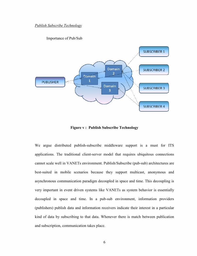
Figure v : Publish Subscribe Technology
We argue distributed publish-subscribe middleware support is a must for ITS
applications. The traditional client-server model that requires ubiquitous connections
cannot scale well in VANETs environment. Publish/Subscribe (pub-sub) architectures are
best-suited in mobile scenarios because they support multicast, anonymous and
asynchronous communication paradigm decoupled in space and time. This decoupling is
very important in event driven systems like VANETs as system behavior is essentially
decoupled in space and time. In a pub-sub environment, information providers
(publishers) publish data and information receivers indicate their interest in a particular
kind of data by subscribing to that data. Whenever there is match between publication
and subscription, communication takes place.
7
Communication in Pub/Sub systems is anonymous meaning that communication partners
are not required to identify each other. The publisher does not identify who the intended
receivers are. The subscribers are implicitly selected based on their subscriptions. Pub-
sub is also inherently asynchronous because publisher does not have to wait for an
acknowledgment from subscriber before moving on. Pub-sub resembles multicast
because it allows a publisher to send the same event to many subscribers with only one
publish operation. Also, the publisher need not be around for the publication to be valid.
Each data can be assigned a time value or a space value which denotes its validity. The
system is therefore able to quickly adapt in a dynamic environment where publishers-
subscribers continuously join and leave.
Vehicular Communication
Types of Vehicular Communication
Vehicular communications can be broadly categorized into
1. Infrastructure based communication where RSUs are set up at regular intervals
along the road which are responsible for information dissemination to vehicles
2. Pure vehicle-to-vehicle communication where vehicles “gossip” among
themselves to disseminate information
3. Hybrid approach which combines the infrastructure with “gossiping” vehicles to
disseminate information.
8
The cost of deployment can be a major issue in the first category whereas in the second,
if the vehicle density is too sparse, information dissemination may not be possible. The
hybrid approach, however, can provide real-time global information and the deployment
cost can be reduced as the physical movement of vehicles can be exploited in areas not
covered by the infrastructure.
Our Communication Choice
In this project we leverage the vehicle-to-vehicle, vehicle-to-road-side-unit and road-side-
unit-to - ITL communication to design a reliable driver alert system for collision
avoidance. Road-side-unit to ITL communication will be used to communicate relevant
information to ITL and will not be a part of the publish subscribe network. It also imparts
possibility of RSU network extension as we will see in later chapters.
Thesis Organization
Rest of the Thesis is organized as follows:
§ The Intelligent Traffic Light System
o Motivation
o ITL Components
o ITL Considerations
o ITL Architecture
§ Estimating safe stopping distance and deceleration for vehicles
§ Optimal Placement of RSUs
o RSU placement problem
o RSU placement solution
9
§ Publish Subscribe Paradigm in ITL
§ Simulation
o Simulation Study
o Simulation Results
§ Future Enhancements and Conclusion
10
CHAPTER II
THE INTELLIGENT TRAFFIC LIGHT SYSTEM
Motivation
Problem to be addressed
As seen before, incidents of red light running can compromise the road safety. With ITL
we intend to deliver timely warning about whether a driver should start decelerating, and
if so what should be his deceleration or whether he can make it safely through the
intersection and should continue his journey. Thus, it is important to keep track of the
current time before light turns red again and the car speed. Also, as mentioned earlier,
road conditions play an important role in deciding the stopping distance for a vehicle.
This information should also be conveyed to the Traffic Light in order to make a correct
estimate for a vehicle.
11
ITL Components
Traffic Light
Figure vi : Intelligent Traffic Light
§ Intelligent Traffic Signals are equipped with Wi-Fi (equipped with 802.11 radio
interface) application. It is also aware of the time frame when light will turn red.
§ ITL communicates with adjacent RSUs to collect information about approaching
vehicles, their distance and speed from the light.
§ Based on this information the Intelligent Traffic Light will calculate critical
safety distance (minimum distance needed to bring vehicle to complete halt
safely) for the car (or fleet of car) and publish it to particular id to start
decelerating if it cannot safely cross the intersection before light turns red.
§ Basic Intelligent Traffic Light Mechanism utilizes RSUs in order to relay
information about approaching vehicles. RSUs will assign vehicles ids (can be
fleet id if the cars form a fleet) and relay their information to the light.
12
Road Side Units (RSUs)
Figure vii : Road Side Unit
§ RSUs are equipped with Wi-Fi and context aware (can sense presence of other
entities in the system) application.
§ They are responsible for Pub/Sub domain creation by assigning each vehicle
unique ID
§ They also run an algorithm for fleet recognition as domains can also be a fleet if
more than one car is traveling together within a range.
§ RSUs relay relevant information about the vehicles to the light.
§ RSUs can also form a network which would behave as an infrastructure to extend
the usability of application for other purposes like congestion control, traffic
monitoring etc.
13
Vehicle
Figure viii : Vehicle
§ Vehicles are equipped with GPS system to convey information about its location
to RSU.
§ Vehicles equipped Wi-Fi application to send and receive messages to traffic light
and dashboard to display acceleration/deceleration and warning messages
received from Traffic Light.
§ Vehicle will display messages indicating if the vehicle should slow down, and the
time duration after which Light will turn red.
§ RSUs will impart id to the car and Traffic Light will publish warning messages to
this ID. This is the domain that vehicles will subscribe to in order to receive
relevant warning messages.
ITL Considerations
Types of Traffic Signals
There are three types of traffic signals.
14
• Pre-timed: A “pre-timed” signal operates on a pre-determined schedule,
regardless of how many cars are present at the intersection. Often, these signals
are timed in coordination with other signals along a roadway. Most signals in
Downtown are pre-timed. These signals do not have detection loops for bicycles
or vehicles, because the green light is programmed to occur on a pre-determined
schedule.
• Fully Actuated: A “fully actuated” signal reacts to the presence of a vehicle
through detection loops in the pavement. A bicycle that is in the center of the
lane and behind the stop bar will trigger the signal just as a car would. Pedestrians
who have pressed the pedestrian button also trigger these signals.
• Semi-Actuated: “Semi-actuated” means that in an intersection of two roads, one
roadway in the intersection is timed and one is actuated. Typically the lower
volume or side street is activated.
Making a choice
All three types of signals can be either in "coordination" or "floating" mode. If a signal is
in coordination, it means its operation is timed in coordination with other signals up and
down the roadway. If a signal is floating, it means the signal reacts to the presence of
cars, independent from other signals, not on a pre-timed schedule. For the purpose of
analysis we will consider pre-timed coordinated signal. These simulation considerations
will provide relevant results which can be easily extended to any other type of signal.
15
ITL Architecture
Typical execution cycle in the system
Typical execution cycle in the system can be describes as follows :
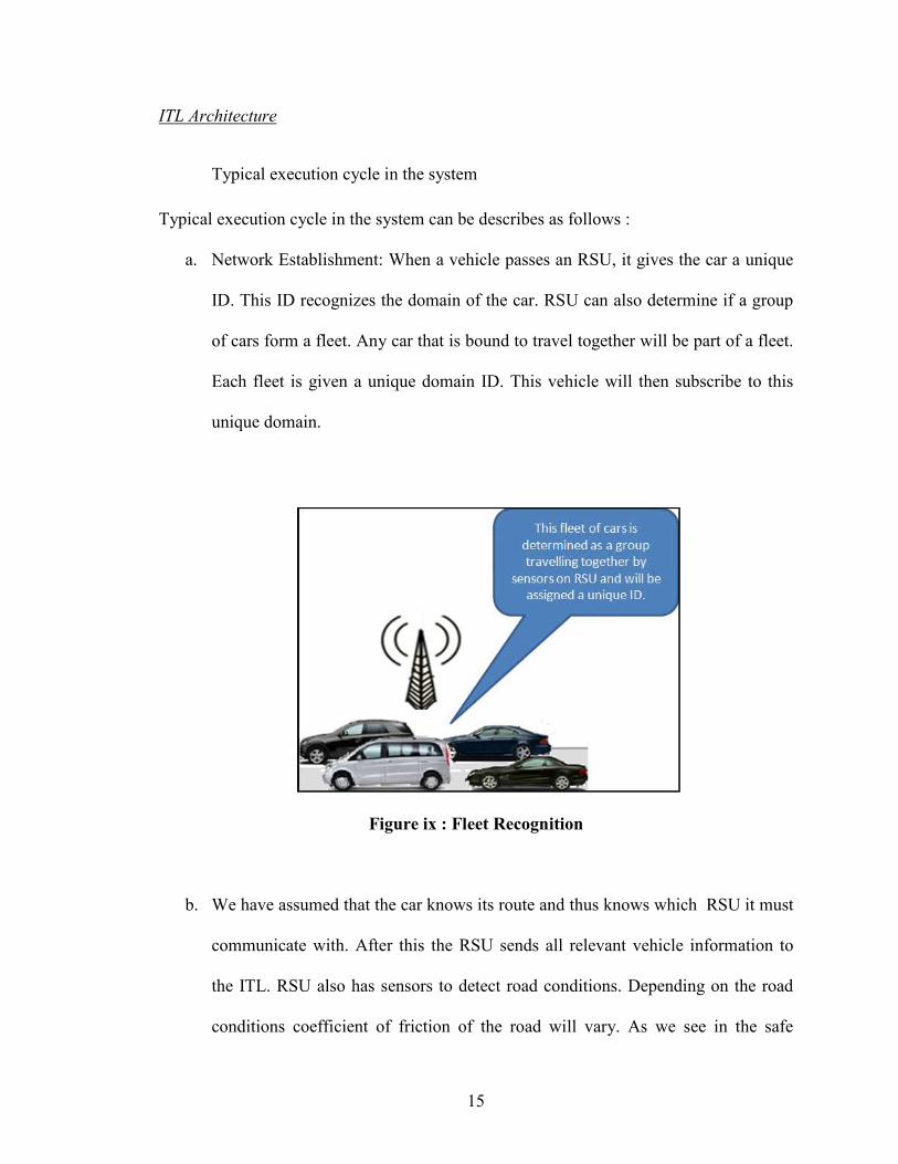
a. Network Establishment: When a vehicle passes an RSU, it gives the car a unique
ID. This ID recognizes the domain of the car. RSU can also determine if a group
of cars form a fleet. Any car that is bound to travel together will be part of a fleet.
Each fleet is given a unique domain ID. This vehicle will then subscribe to this
unique domain.
Figure ix : Fleet Recognition
b. We have assumed that the car knows its route and thus knows which RSU it must
communicate with. After this the RSU sends all relevant vehicle information to
the ITL. RSU also has sensors to detect road conditions. Depending on the road
conditions coefficient of friction of the road will vary. As we see in the safe
16
breaking distance calculation, coefficient of friction affects the distance needed by
a vehicle to come to complete halt.
c. When ITL receives this information from RSU, it indentifies the domain ID in the
message and uses location, speed information in the message to determine if the
vehicle can pass safely through the intersection without breaking. As mentioned
earlier, in our system the pre-timed signal will keep track of time remaining for
the light to turn red (tred). Comparing this time to safe breaking distance (tsafe) ITL
can easily determine need to halt and deceleration. Thus if
tred < tsafe
Time remaining to bring the vehicle to complete halt is
trem = tsafe - tred
Thus deceleration needed is Vcur - 0 / trem
d. These results are then published to the relevant domain. Cars that have subscribed
to this domain read these messages and display it on the dashboard.
17
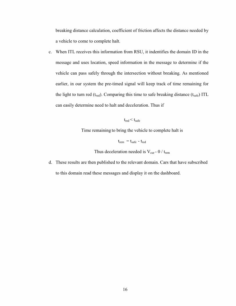
Summary of event flow
Figure x : Event Flow in ITL
Thus event Flow in the ITL system can be summarized as:
• Subscribe: When vehicles pass an RSU, they are assigned an ID that recognizes
domain for this vehicle. They subscribe to this domain for warning messages.
• Publish: Publish is event driven. It is governed by the event of traffic light
receiving information from RSU. ITL will estimate the time for light to turn red
and publish messages accordingly to the particular domain.
• Information Dissemination among car fleet: Cars in a particular range that need to
receive the same warning message (cars which are at the same distance from the
light) will read it from the same domain.
18
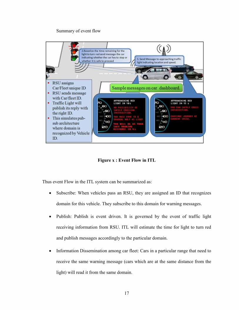
Need for RSUs
Figure xi : Sample RSU Network Application
As said before, RSUs provide extensibility to our application model. Let us look into the
details of the same. Vision of extending this application to a more complete system where
RSUs communicate with each other and propagate relevant information to other RSUs in
the network necessitates use of RSUs in the network. They not only provide a convenient
information dissemination method but also provide enhancement capabilities to the
application. An example that justifies this, consider a network where is traffic congestion
information that could be conveyed via RSU network to vehicles. Vehicles could then
modify their route considering this real time data.
Estimating safe stopping distance and deceleration for vehicles
Background
Safe stopping distance or critical safety distance can be defined as the minimum distance
needed to bring vehicle to complete halt safely. Highway traffic and safety engineers
have some general guidelines they have developed over the years and hold now as
19
standards. As an example, if a street surface is dry, the average driver can safely
decelerate an automobile or light truck with reasonably good tires at the rate of about 15
feet per second (fps). That is, a driver can slow down at this rate without anticipated
probability that control of the vehicle will be lost in the process.
The measure of velocity is distance divided by time (fps), stated as feet per second. The
measure of acceleration (or deceleration in this case) is feet per second per second. That
assumes a reasonably good co-efficient of friction of about .75; better is .8 or higher
while conditions or tire quality might yield a worse factor of .7 or lower.
No matter the velocity, that velocity is reduced 15 fps every second. If the initial velocity
is 60 mph, 88 fps, after 1 second elapsed, the vehicle velocity would be 73 fps, after 2
seconds it would be 58 fps decreasing progressively thereafter.
Given the previous set of conditions, it would mean that a driver could stop the described
vehicle in a total of 6.87 seconds (including a 1 second delay for driver reaction) and
your total stopping distance would be 302.28 feet.
Virtually all current production vehicles' published road braking performance tests
indicate stopping distances from 60 mph that are typically 120 to 140 feet, slightly less
than half of the projected safety distances. While the figures are probably achievable,
they are not realistic and certainly not average; they tend to be misleading and to those
that actually read them, they create a false sense of security.
20
Under closed course conditions, professional drivers frequently achieve 1g deceleration
(32 fpsps) or better. A reasonably skilled driver could easily get deceleration rates in
excess of 20 fpsps without loss of control. It is very possible and probable that with some
effort, the driver that attempts to be aware of braking safety procedures and practices can
and should get much better braking (safely) than the guidelines used nationally,
approaching that of the professionally driver published performance tests.
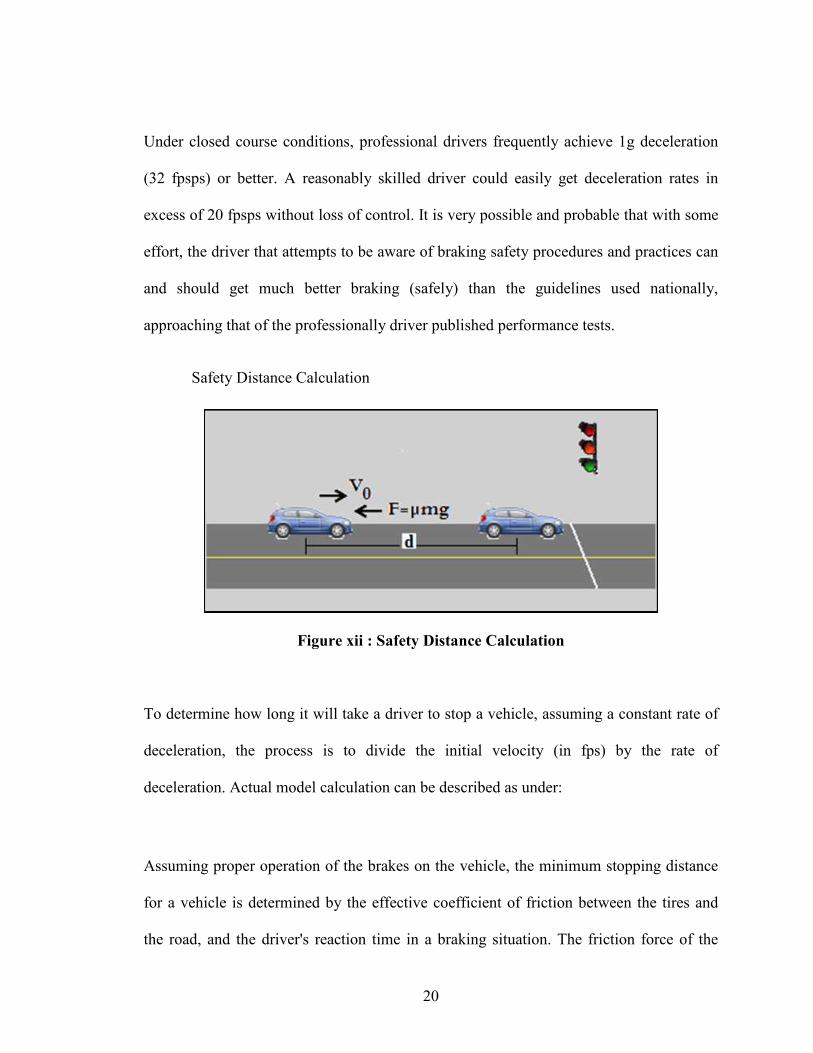
Safety Distance Calculation
Figure xii : Safety Distance Calculation
To determine how long it will take a driver to stop a vehicle, assuming a constant rate of
deceleration, the process is to divide the initial velocity (in fps) by the rate of
deceleration. Actual model calculation can be described as under:
Assuming proper operation of the brakes on the vehicle, the minimum stopping distance
for a vehicle is determined by the effective coefficient of friction between the tires and
the road, and the driver's reaction time in a braking situation. The friction force of the
21
road must do enough work on the car to reduce its kinetic energy to zero. If the wheels of
the car continue to turn while braking, then static friction is operating, while if the wheels
are locked and sliding over the road surface, the braking force is a kinetic friction force
only.
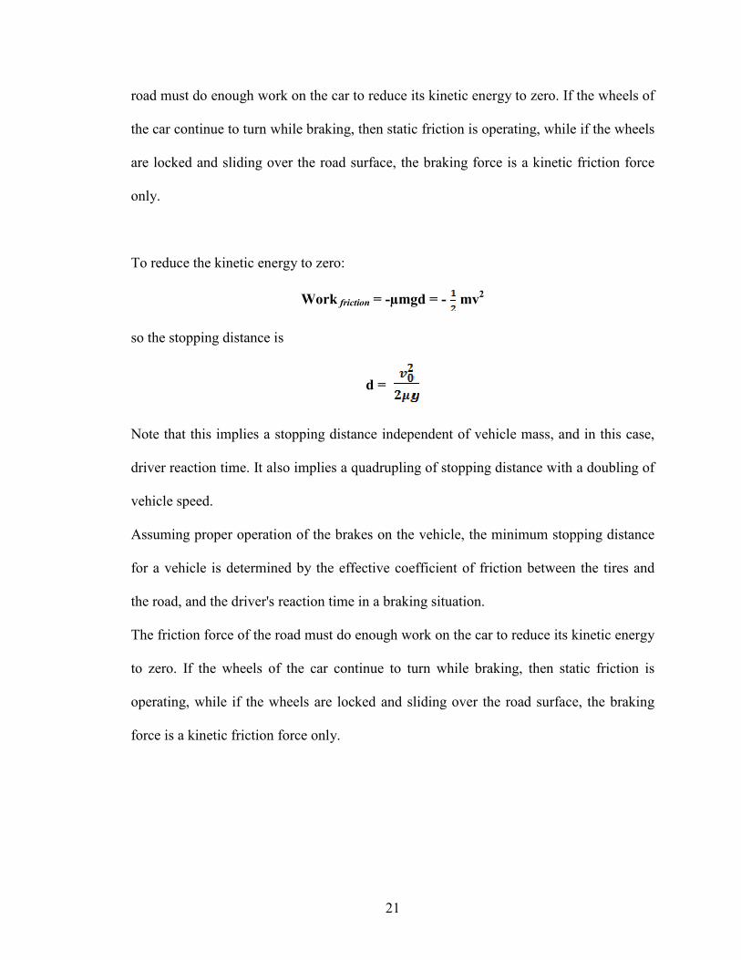
To reduce the kinetic energy to zero:
Work friction = -µmgd = - mv2
so the stopping distance is
d =
Note that this implies a stopping distance independent of vehicle mass, and in this case,
driver reaction time. It also implies a quadrupling of stopping distance with a doubling of
vehicle speed.
Assuming proper operation of the brakes on the vehicle, the minimum stopping distance
for a vehicle is determined by the effective coefficient of friction between the tires and
the road, and the driver's reaction time in a braking situation.
The friction force of the road must do enough work on the car to reduce its kinetic energy
to zero. If the wheels of the car continue to turn while braking, then static friction is
operating, while if the wheels are locked and sliding over the road surface, the braking
force is a kinetic friction force only.
22
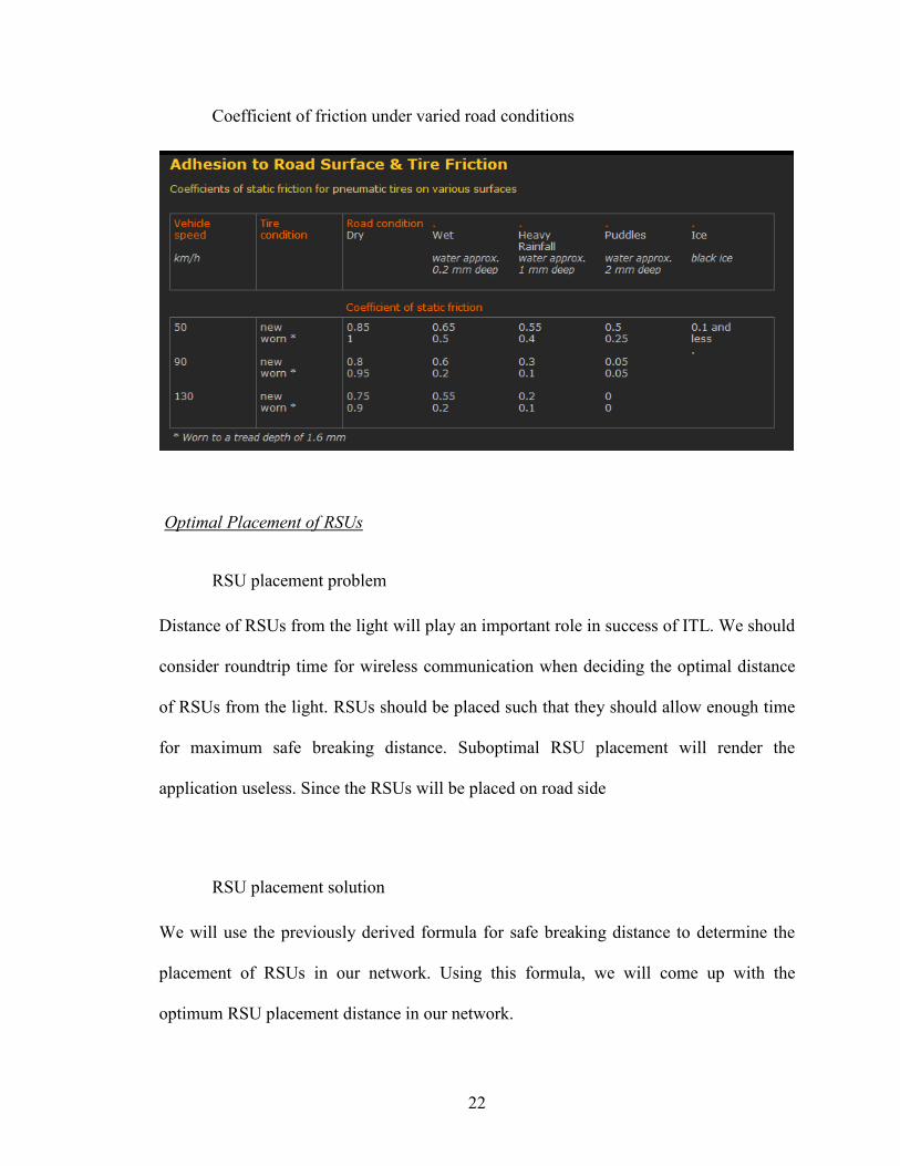
Coefficient of friction under varied road conditions
Optimal Placement of RSUs
RSU placement problem
Distance of RSUs from the light will play an important role in success of ITL. We should
consider roundtrip time for wireless communication when deciding the optimal distance
of RSUs from the light. RSUs should be placed such that they should allow enough time
for maximum safe breaking distance. Suboptimal RSU placement will render the
application useless. Since the RSUs will be placed on road side
RSU placement solution
We will use the previously derived formula for safe breaking distance to determine the
placement of RSUs in our network. Using this formula, we will come up with the
optimum RSU placement distance in our network.
23
Maximum speed limit within counties in USA (except freeways) is
55 mph =24.93 m/s ~ 25 m/s
Thus minimum safe breaking distance for maximum speed is (assuming low coefficient
of friction .4)
25x25 / (2x0.4x9.8) ~ 80 m.
Thus we can safely place our RSU at 90 m from the light. (WLAN communication range
for NIC 80211 is 100m).
Thus, if ITL finds that the vehicle will not make it through, it informs the car about it and
alerts it about its safe breaking distance. (WLAN roundtrip is assumed to be negligible,
average is .85 ms).
Publish Subscribe Paradigm in ITL
As stated earlier, Publish/subscribe architecture used in this system is best suited for our
purpose. Pub/Sub is an asynchronous messaging paradigm where publishers of messages
are not programmed to send their messages to specific subscribers. Rather, published
messages are characterized into classes, without knowledge of what subscribers there
may be. Subscribers express interest in one or more classes, and only receive messages
that are of interest, without knowledge of what publishers there are. This decoupling of
publishers and subscribers can allow for greater scalability and a more dynamic network
topology
24
ITL needs real-time, scalable and reliable delivery of information. ITL also has very strict
time constraints, like a driver needs to get a red light warning within the time he gets in
range and before he needs to decelerate if the vehicle has to be stopped. Scalability
becomes critical because the number of vehicles on the road can increase. Reliable
dissemination as well as priority based service is required for many ITS applications to
become useful. For example, special vehicle notification information needs to be
disseminated to security people as fast as possible to warn vehicles that even though they
can make it in time they need to stop at the next signal. Thus all these parameters make
Pub/Sub optimum for our application.
25
CHAPTER III
SIMULATION
Omnet++/INET
Introduction
OMNeT++ is an extensible, modular, component-based C++ simulation library and
framework, with an Eclipse-based IDE and a graphical runtime environment. Domain-
specific functionality (support for simulation of communication networks, queuing
networks, performance evaluation, etc.) is provided by model frameworks, developed as
independent projects. There are extensions for real-time simulation, network emulation,
alternative programming languages (Java, C#), database integration, SystemC integration,
and several other functions. OMNeT++ provides a component architecture for models.
Components (modules) are programmed in C++, then assembled into larger components
and models using a high-level language (NED). Reusability of models comes for free.
OMNeT++ has extensive GUI support, and due to its modular architecture, the
simulation kernel (and models) can be embedded easily into your applications.
OMNeT++ has a generic architecture, so it can be (and has been) used in various problem
domains:
§ modeling of wired and wireless communication networks
26
§ protocol modeling
§ modeling of multiprocessors and other distributed hardware systems
§ validating of hardware architectures
§ evaluating performance aspects of complex software systems
§ simulation of any system where the discrete event approach is suitable, and which
can be conveniently mapped into entities communicating by exchanging
messages.
The INET Framework builds upon OMNeT++, and uses the same concept: modules
communicating by message passing. INET Framework contains IPv4, IPv6, TCP, UDP
protocol implementations, and several application models. The framework also includes
an MPLS model with RSVP-TE and LDP signalling. Link-layer models are PPP,
Ethernet and 802.11. Static routing can be set up using network autoconfigurators, or one
can use routing protocol implementations. MANET Framework has various mobility
modules that can be easily utilized by mobile hosts. The INET Framework supports
wireless and mobile simulations as well.
Modules Used
Channel Control
This module takes care of establishing communication channels between nodes that are
within communication distance and tearing down the connections when they move out of
range. This information is used by the radio interfaces of nodes at transmissions. For
mobile hosts, the Mobility Controller module recalculates its position regularly and
27
updates the graphical representation of its host and communicates the current location
information to the Channel Control.
FlatNetworkConfigurator
This module configures IP addresses and routing tables for a "flat" network, "flat"
meaning that all hosts and routers will have the same network address and will only differ
in the host part. The module runs at the beginning of the simulation and it assigns IP
addresses to cars and rsus. It then discovers the topology of the network (using
OMNeT++'s cTopology class), and calculate shortest paths, and finally, adds routes
which correspond to the shortest paths to the routing tables.
The configurator picks all modules of types listed in the moduleTypes parameter and
their connections, and builds a graph from it. Then it runs Dijstra's shortest path
algorithm on it, and configures all modules which are IP nodes, that is, not listed in the
nonIPModuleTypes parameter.
28
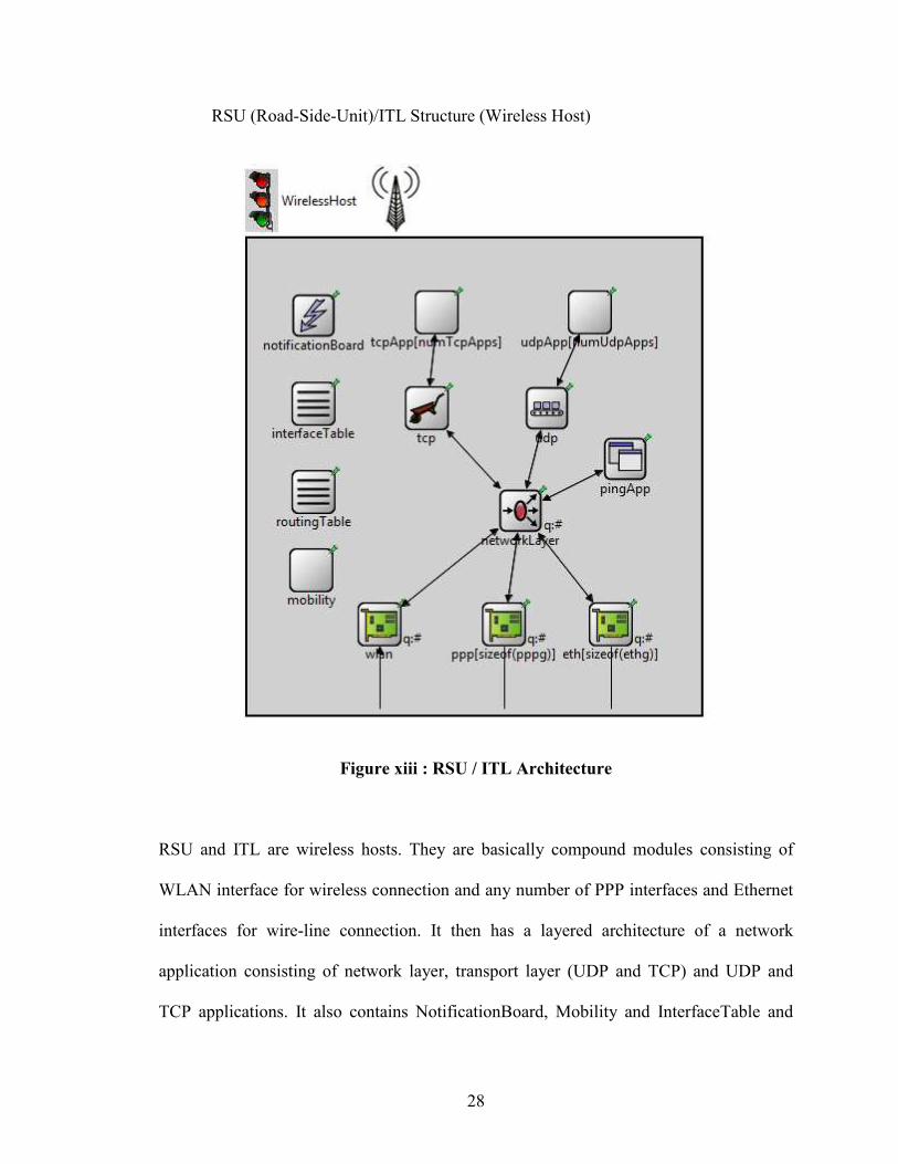
RSU (Road-Side-Unit)/ITL Structure (Wireless Host)
Figure xiii : RSU / ITL Architecture
RSU and ITL are wireless hosts. They are basically compound modules consisting of
WLAN interface for wireless connection and any number of PPP interfaces and Ethernet
interfaces for wire-line connection. It then has a layered architecture of a network
application consisting of network layer, transport layer (UDP and TCP) and UDP and
TCP applications. It also contains NotificationBoard, Mobility and InterfaceTable and
29
RoutingTable modules. As seen in the above diagram, mobile host has OSI layer
implementation. Omnet also provides capability to analyze each layer and each packet
that is being transmitted within layers. It is possible to generate graphs to estimate system
performance.
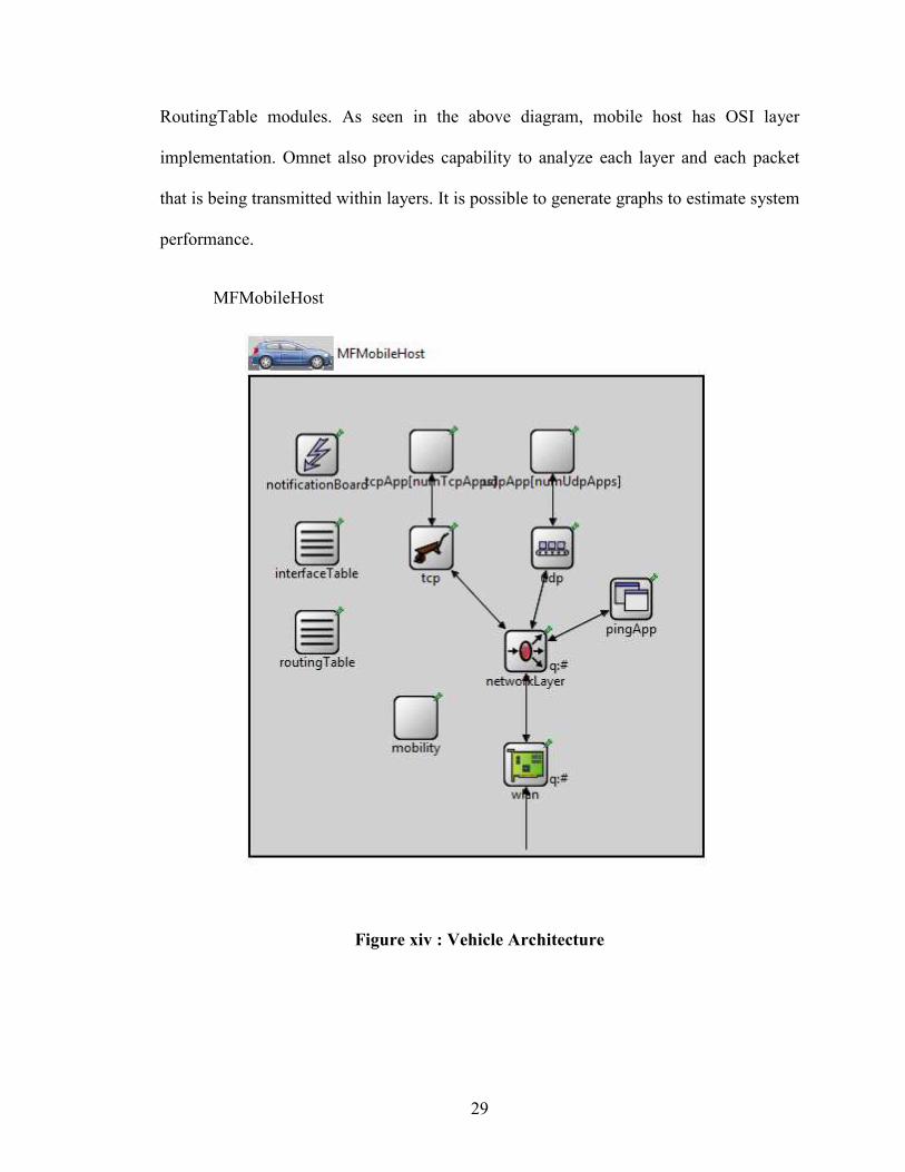
MFMobileHost
Figure xiv : Vehicle Architecture
30
It is a compound module consisting of WLAN (802.11) radio interface in adhoc mode. It
then has a layered architecture of a network application consisting of network layer,
transport layer (UDP and TCP) and UDP and TCP applications. It also contains
NotificationBoard, Mobility and InterfaceTable and RoutingTable modules.
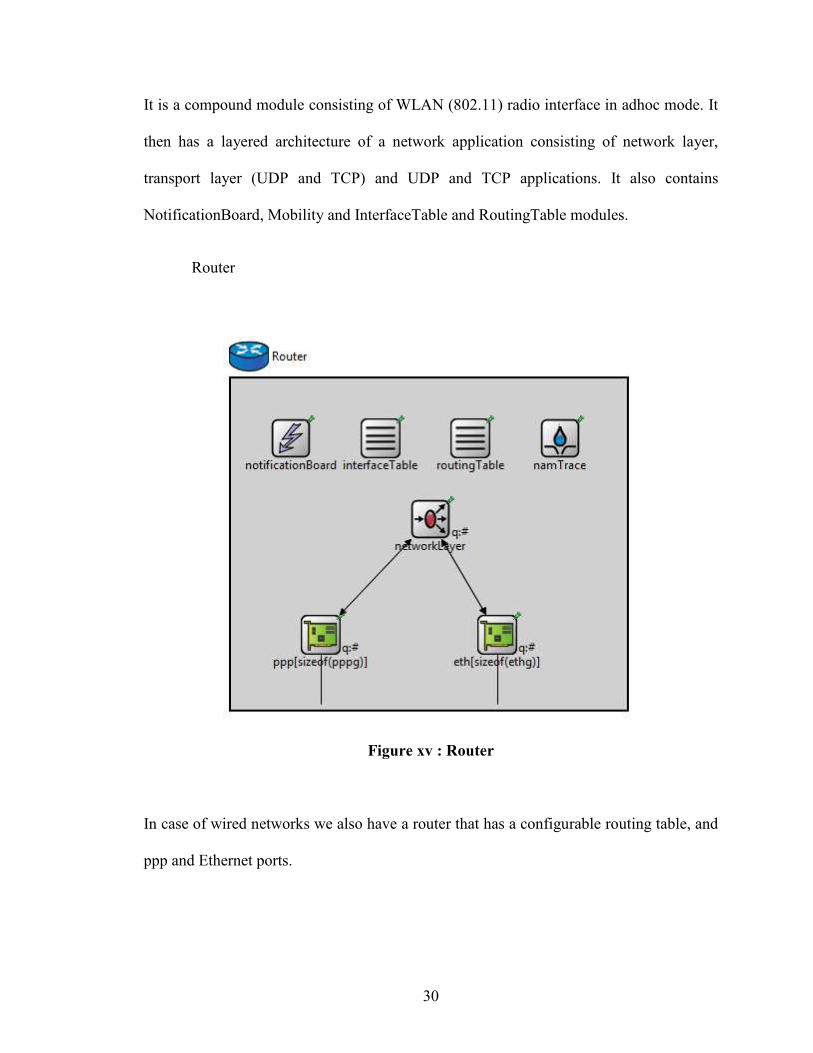
Router
Figure xv : Router
In case of wired networks we also have a router that has a configurable routing table, and
ppp and Ethernet ports.
31
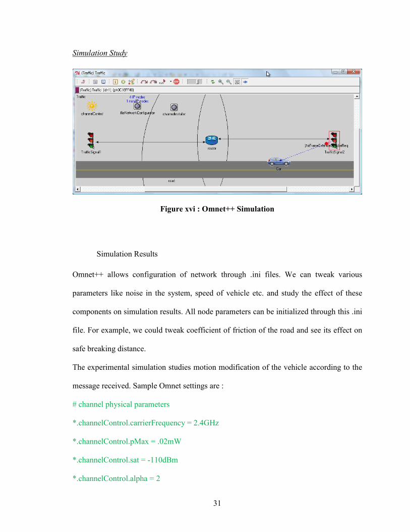
Simulation Study
Figure xvi : Omnet++ Simulation
Simulation Results
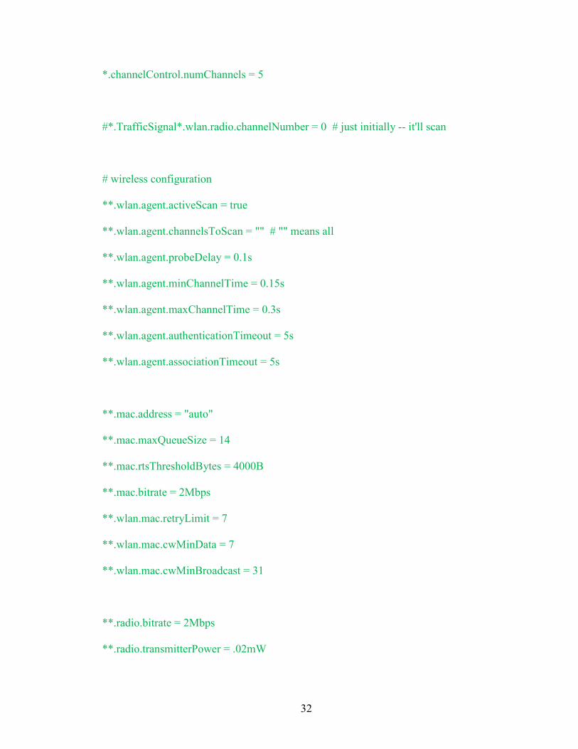
Omnet++ allows configuration of network through .ini files. We can tweak various
parameters like noise in the system, speed of vehicle etc. and study the effect of these
components on simulation results. All node parameters can be initialized through this .ini
file. For example, we could tweak coefficient of friction of the road and see its effect on
safe breaking distance.
The experimental simulation studies motion modification of the vehicle according to the
message received. Sample Omnet settings are :
# channel physical parameters
*.channelControl.carrierFrequency = 2.4GHz
*.channelControl.pMax = .02mW
*.channelControl.sat = -110dBm
*.channelControl.alpha = 2
32
*.channelControl.numChannels = 5
#*.TrafficSignal*.wlan.radio.channelNumber = 0 # just initially -- it'll scan
# wireless configuration
**.wlan.agent.activeScan = true
**.wlan.agent.channelsToScan = "" # "" means all
**.wlan.agent.probeDelay = 0.1s
**.wlan.agent.minChannelTime = 0.15s
**.wlan.agent.maxChannelTime = 0.3s
**.wlan.agent.authenticationTimeout = 5s
**.wlan.agent.associationTimeout = 5s
**.mac.address = "auto"
**.mac.maxQueueSize = 14
**.mac.rtsThresholdBytes = 4000B
**.mac.bitrate = 2Mbps
**.wlan.mac.retryLimit = 7
**.wlan.mac.cwMinData = 7
**.wlan.mac.cwMinBroadcast = 31
**.radio.bitrate = 2Mbps
**.radio.transmitterPower = .02mW
33
**.radio.thermalNoise = -110dBm
**.radio.sensitivity = -.5dBm
**.radio.pathLossAlpha = 2
**.radio.snirThreshold = 4dB
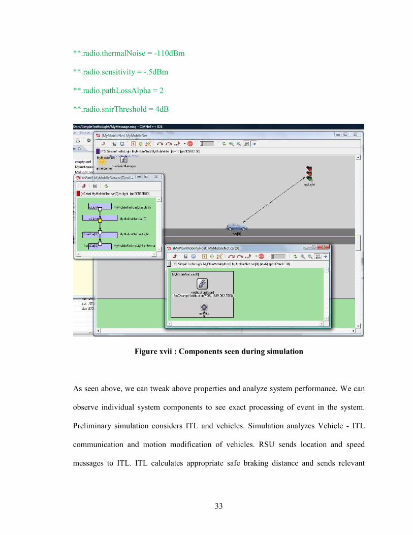
Figure xvii : Components seen during simulation
As seen above, we can tweak above properties and analyze system performance. We can
observe individual system components to see exact processing of event in the system.
Preliminary simulation considers ITL and vehicles. Simulation analyzes Vehicle - ITL
communication and motion modification of vehicles. RSU sends location and speed
messages to ITL. ITL calculates appropriate safe braking distance and sends relevant
34
warning message to the vehicles. Vehicles modify their motion as appropriate to the
message received.
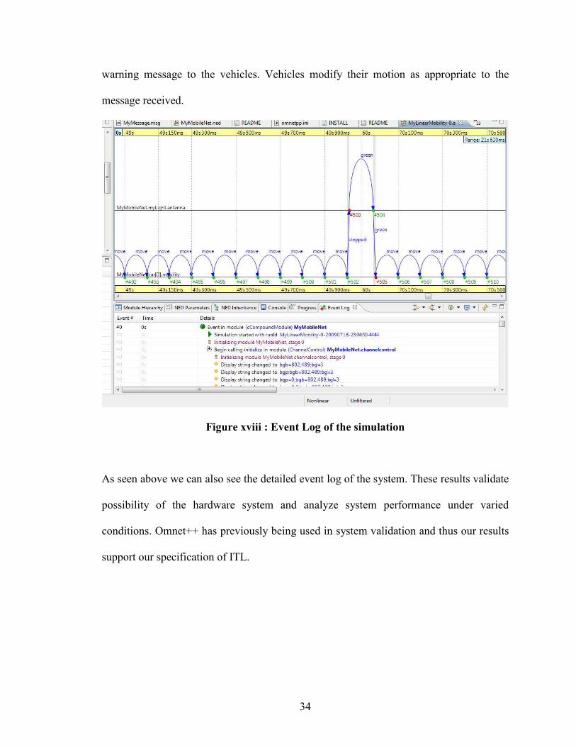
Figure xviii : Event Log of the simulation
As seen above we can also see the detailed event log of the system. These results validate
possibility of the hardware system and analyze system performance under varied
conditions. Omnet++ has previously being used in system validation and thus our results
support our specification of ITL.
35
CHAPTER IV
FUTURE ENHANCEMENTS AND CONCLUSION
Future Enhancements and Conclusion
Conclusion
ITS applications currently in existence, and being developed, have tremendous potential
to reduce the incidence and severity of road crashes. The deployment of Intelligent
Transport Systems (ITS) technologies has the potential to yield a new wave of road safety
and other benefits. This thesis concludes with recommendations for future action and
research to better understand and exploit the potential safety benefits of ITS for all road
users. ITL also considers adverse conditions like fog, rain which affects traffic light
visibility and makes relaying of warning messages in these conditions possible too.
Simulation results support the possibility of a hardware system that will function
according to the suggested specifications. Simulation also allows study of the system
under varied physical and real time conditions and thus provides a very well suited
validity testing for the system.
Future Enhancements
Future enhancements could include consideration of special vehicles by ITL. Special
vehicles like ambulance, fire brigade etc which need vehicles to modify their travel speed
could be equipped with special equipment to converse with Traffic Light. ITL could then
36
include the approach of these vehicles in messages that they relay to vehicles. ITL could
also behave as congestion control unit by being part of RSU network and thus relaying
relevant congestion information to vehicles.
37
REFERENCES
[1] Richard A. Retting, Susan A. Ferguson, Charles M. Farmer, Reducing red light running through longer yellow signal timing and red light camera enforcement: Results of a field investigation
[2] Jeroen Idserda, TCP/IP modeling in OMNeT++, University of Twente, The Netherlands, July 2004.
[3] Roland Bless and Mark Doll. Integration of the FreeBSD TCP/IP-Stackinto the Discrete Event Simulator OMNeT++. Proceedings of the 2004 Winter Simulation Conference.
[4] J. Rybicki, B. Scheuermann, W. Kiess, C. Lochert, P. Fallahi, M. Mauve. Challenge: Peers on Wheels - A Road to New Traffc Information Systems. MobiCom 2007: Proceedings of the 13th Annual International Conference on Mobile Computing and Networking, pp. 215{221, Montreal, Quebec, Canada, September 2007.
[5] Yongqiang Hange and Hector Garcia-Molina. Publish/Subscribe in a Mobile Environment. 2nd ACM International Workshop on Data Engineering for Wireless and Mobile Access (MobiDE 2001) , May 20, 2001, Santa Barbara, California.
[6] Nandan, S. Das, G. Pau, M. Gerla, M. Y.Sanadidi. Co-operative downloading in vehicular ad-hoc wireless networks. Wireless On-demand Network Systems and Services, 2005. WONS 2005. Second Annual Conference on , vol., no., pp. 32-41, 19-21 Jan. 2005.
[7] M. Kihl, M. Sichitiu, T. Ekeroth, M. Rozenberg. Reliable Geographical Multicast Routing in Vehicular Ad-hoc Networks. Proc. of the International Conference on Wireless/Wired Internet Communications (WWIC 2007), (Coimbra, Portugal), May 2007.
[8] W. Sun, H. Yamaguchi, K. Yukimasa, S. Kusumoto. GVGrid: A QoS Routing Protocol for Vehicular Ad Hoc Networks. Quality of Service, 2006. IWQoS 2006. 14th IEEE International Workshop on, vol., no., pp.130-139, 19-21 June 23006.
[9] Petit, M. Ammar, R. Fujimoto. Protocols for roadside-to-roadside data relaying over vehicular networks. Wireless Communications and Networking Conference, 2006. WCNC 2006. IEEE , vol.1, no., pp.294-299, 3-6 April 2006.
[10] Leontiadis, C. Mascolo. GeOpps: Opportunistic Geographical Routing for Vehicular Networks World of Wireless, Mobile and Multimedia Networks, 2007. WoWMoM 2007. IEEE International Symposium on a , vol., no., pp.1-6, 18-21 June 2007.
38
[11] Leontiadis. Publish/subscribe notification middleware for vehicular networks. MDS '07: Proceedings of the 4th on Middleware doctoral symposium, pages 1-6, New York, NY, USA, 2007. ACM
[12] H. Wu, R. Fujimoto, R. Guensler, M. Hunter. MDDV: a mobility-centric data dissemination algorithm for vehicular networks. In VANET '04: Proceedings of the 1st ACM international workshop on Vehicular ad hoc networks, pages 47-56, New York, NY, USA, 2004. ACM Press.
[13] Skordylis, N. Trigoni. Delay-bounded routing in vehicular ad-hoc networks. Mobi-Hoc '08: Proceedings of the 9th ACM international symposium on Mobile ad hoc networking and computing, pages 341-350, Hong Kong, Hong Kong, China, 2008. ACM Press.
[14] www.omnet.org
[15] W. Drytkiewicz, S. Sroka, V. Handziski, A. Kopke, H. Karl. A Mobility Framework for OMNeT++.
