a proposed approach to mechatronics design and implementation … · a proposed approach to...
TRANSCRIPT

Journal of Multidisciplinary Engineering Science and Technology (JMEST) ISSN: 3159-0040
Vol. 1 Issue 3, October - 2014
A Proposed Approach To Mechatronics Design And Implementation Education-Oriented Methodology,Case
Study; Mechatronics Design Of Smart Guidance System-Smart Mechatronics Wheelchair
Farhan A. Salem
Mechatronics engineering program, Department of Mechanical Engineering, College of Engineering, Taif University, 888, Taif, Saudi Arabia. Alpha center for Engineering Studies and Technology Researches, Amman,
Jordan. Email: [email protected]
Abstract—Mechatronics engineer is expected to design engineering systems with synergy and integration toward constrains like higher performance, speed, precision, efficiency, lower costs and functionality. The key element in success of a mechatronics engineering education-program, and correspondingly, Mechatronics engineering graduates, is directly related to a well-structured mechatronic system design course and the applied structural design methodology. The design and implementation of functional prototypes are an essential learning experience for Mechatronics students. This paper extends writer’s previous work on proposed Mechatronics system design and implementation education-oriented Methodology, that is presented, explained, discussed and applied in this paper, with the help of example student final year graduation project; design and implementation of mechatronics smart mobile robotic guidance system in the from of smart wheelchair, to help and support people with disabilities and special needs to perform specific predetermined ritual tasks, particularly, performing Al Omrah-Tawaf motions around holy Kaba and and Al-Sa’ae, Makka. The proposed design methodology aims to integrate multidisciplinary knowledge, in various stages through the design process and development of mechatronics product, the proposed methodology is based on V-model and consists of a systematic simple, clear, easy to memorize and follow design steps that can support engineering educators, and help non experienced student or group of students, in solving mechatronics design tasks.
Keywords—Mechatronics education, Design methodology, Parallel design, Synergy, Integration, Interdesiplinary, Mobile robot, Motawif.
I. INTRODUCTION Mechatronics engineer is expected to design products with synergy and integration toward constrains like higher performance, speed, precision, efficiency, lower costs and functionality. Also in order to evaluate concepts generated during the design process, without building and testing each one, mechatronics engineer must be skilled in the modeling, simulation analysis, and control of dynamic systems and understand the key issues in hardware
implementation[1-2]. The key element in success of a mechatronics engineering program, and correspondingly Mechatronics engineering graduates, is directly related to the applied structural design methodology. Engineering educators face daunting challenges, where due to different disciplines involved, the mechatronics design process may become very complex, therefore specific guidelines for structural design methodology and tools for the development process of mechatronic products, that can support students in solving mechatronics design tasks with their specific properties and can be applied in educational process is highly required. This paper extends writer’s previous work [1-2] that proposes an approach for Mechatronics system design and implementation education-oriented Methodology, , the proposed methodology in [2] is to be applied, explained and discussed with the help of example student final year graduation project; design and implementation of mechatronics smart mobile robotic guidance system in the from of smart wheelchair- Mechatronics Motawif, to help and support people with disabilities and special needs to perform specific predetermined Al Omrah ritual tasks, particularly, performing Tawaf motions around holy Kaba and Sa’ae, Makka Almukarramah. The proposed design methodology aims to integrate multidisciplinary knowledge, in various stages through the design process and development of mechatronics product, the proposed methodology is based on V-model and consists of a systematic simple, clear, easy to memorize and follow design steps (shown in diagram Figure 1), intended to support engineering educators, and help non experienced student or group of students, in solving mechatronics design tasks. Mechatronics can be defined as multidisciplinary concept, it is synergistic integration of mechanical engineering, electric engineering, electronic systems, information technology, intelligent control system, and computer hardware and software to manage complexity, uncertainty, and communication through the design and manufacture of products and processes from the very start of the design process, thus enabling complex decision making. Modern products are considered mechatronics products, since,
www.jmest.org JMESTN42350092 135
Journal of Multidisciplinary Engineering Science and Technology (JMEST) ISSN: 3159-0040
Vol. 1 Issue 3, October - 2014
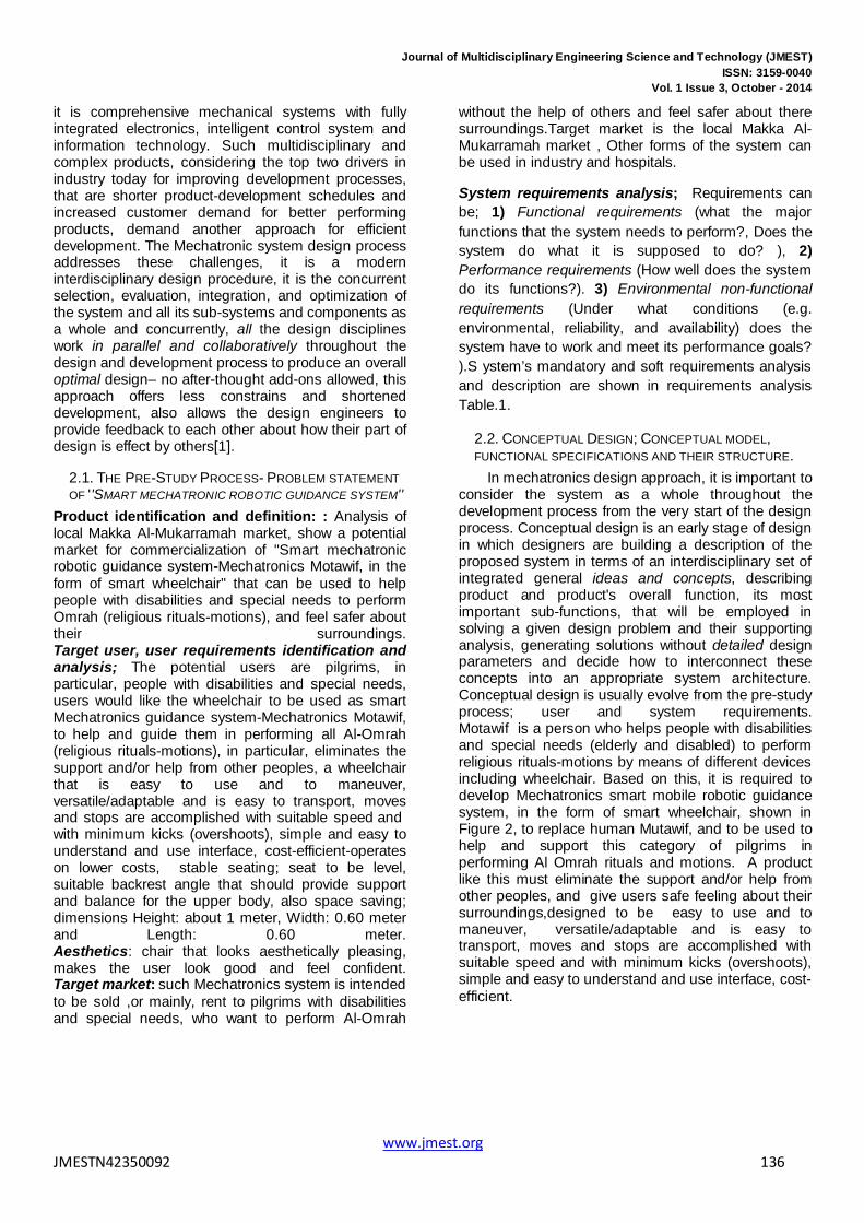
it is comprehensive mechanical systems with fully integrated electronics, intelligent control system and information technology. Such multidisciplinary and complex products, considering the top two drivers in industry today for improving development processes, that are shorter product-development schedules and increased customer demand for better performing products, demand another approach for efficient development. The Mechatronic system design process addresses these challenges, it is a modern interdisciplinary design procedure, it is the concurrent selection, evaluation, integration, and optimization of the system and all its sub-systems and components as a whole and concurrently, all the design disciplines work in parallel and collaboratively throughout the design and development process to produce an overall optimal design– no after-thought add-ons allowed, this approach offers less constrains and shortened development, also allows the design engineers to provide feedback to each other about how their part of design is effect by others[1].
2.1. THE PRE-STUDY PROCESS- PROBLEM STATEMENT OF ''SMART MECHATRONIC ROBOTIC GUIDANCE SYSTEM''
Product identification and definition: : Analysis of local Makka Al-Mukarramah market, show a potential market for commercialization of ''Smart mechatronic robotic guidance system-Mechatronics Motawif, in the form of smart wheelchair'' that can be used to help people with disabilities and special needs to perform Omrah (religious rituals-motions), and feel safer about their surroundings. Target user, user requirements identification and analysis; The potential users are pilgrims, in particular, people with disabilities and special needs, users would like the wheelchair to be used as smart Mechatronics guidance system-Mechatronics Motawif, to help and guide them in performing all Al-Omrah (religious rituals-motions), in particular, eliminates the support and/or help from other peoples, a wheelchair that is easy to use and to maneuver, versatile/adaptable and is easy to transport, moves and stops are accomplished with suitable speed and with minimum kicks (overshoots), simple and easy to understand and use interface, cost-efficient-operates on lower costs, stable seating; seat to be level, suitable backrest angle that should provide support and balance for the upper body, also space saving; dimensions Height: about 1 meter, Width: 0.60 meter and Length: 0.60 meter. Aesthetics: chair that looks aesthetically pleasing, makes the user look good and feel confident. Target market: such Mechatronics system is intended to be sold ,or mainly, rent to pilgrims with disabilities and special needs, who want to perform Al-Omrah
without the help of others and feel safer about there surroundings.Target market is the local Makka Al-Mukarramah market , Other forms of the system can be used in industry and hospitals.
System requirements analysis; Requirements can be; 1) Functional requirements (what the major functions that the system needs to perform?, Does the system do what it is supposed to do? ), 2) Performance requirements (How well does the system do its functions?). 3) Environmental non-functional requirements (Under what conditions (e.g. environmental, reliability, and availability) does the system have to work and meet its performance goals? ).S ystem’s mandatory and soft requirements analysis and description are shown in requirements analysis Table.1.
2.2. CONCEPTUAL DESIGN; CONCEPTUAL MODEL, FUNCTIONAL SPECIFICATIONS AND THEIR STRUCTURE.
In mechatronics design approach, it is important to consider the system as a whole throughout the development process from the very start of the design process. Conceptual design is an early stage of design in which designers are building a description of the proposed system in terms of an interdisciplinary set of integrated general ideas and concepts, describing product and product's overall function, its most important sub-functions, that will be employed in solving a given design problem and their supporting analysis, generating solutions without detailed design parameters and decide how to interconnect these concepts into an appropriate system architecture. Conceptual design is usually evolve from the pre-study process; user and system requirements. Motawif is a person who helps people with disabilities and special needs (elderly and disabled) to perform religious rituals-motions by means of different devices including wheelchair. Based on this, it is required to develop Mechatronics smart mobile robotic guidance system, in the form of smart wheelchair, shown in Figure 2, to replace human Mutawif, and to be used to help and support this category of pilgrims in performing Al Omrah rituals and motions. A product like this must eliminate the support and/or help from other peoples, and give users safe feeling about their surroundings,designed to be easy to use and to maneuver, versatile/adaptable and is easy to transport, moves and stops are accomplished with suitable speed and with minimum kicks (overshoots), simple and easy to understand and use interface, cost-efficient.
www.jmest.org JMESTN42350092 136

Journal of Multidisciplinary Engineering Science and Technology (JMEST) ISSN: 3159-0040
Vol. 1 Issue 3, October - 2014
Figure 1 Systematic guideline steps for mechatronics systems design education-oriented methodology
www.jmest.org JMESTN42350092 137

Journal of Multidisciplinary Engineering Science and Technology (JMEST) ISSN: 3159-0040
Vol. 1 Issue 3, October - 2014
Table.1 Requirements analysis
Requirements TYPE Unit-Value
Qualitative Req.
Quantitative Req.
Soft Req.
Mandatory (fixed) Req.
Discreption
Requirements
Qual. Fixed
100 cm Height: Smart Wheelchair
Mechanical structure & dimensions
60 cm Width:
60 cm Length: Qual Soft See Fig5-.6 & Table 3 Mechanical
requirements: materials & mechanical structure
Qual 12-24 V Electric battery Power supply Qual. Quan. fixed Electric Actuators Qual. Quan.. Soft - Path finder; line, color,
Sensors Load, speed Obstacle det., Timers
p Soft Fixed Simple, compact , cost effective
Controller
Fixed Fixed Simple, precise, quick, efficient, easy to program
Control algorithm
Qual. Soft n Gears, belts ,chain Transmission Fixed Drives : electronic and
mechanical Interfaces.
Qual. Soft Joy-stock , switches Manual control Qual. - Fixed Simple and easy to use
and understand User interface
Qual Fixed Chairs looks aesthetically pleasing makes the user look good and feel confident.
Machine aesthetics design
fixed easy to use and to maneuver, Per formance requirements
Qual. - Fixed
0.5 m/s, in 1 sec.
allowable speed: Suit able smooth speed moves and stops are accomplished with suitable speed and with minimum kicks (overshoots)d, Minimum kick
soft Work under repeated moves and stops
Environmental non-functional requirement
Qual. Soft 120 kg allowable user weight: M ax. Allowable
Figure 2 Preliminary concept of robotic guidance system, in the form of wheelchair.
The tasks (functions) to be carried out by the proposed design: is intended to help and guide user to perform religious rituals-motions of Al-Omrah and/or Al-Hajj, mainly performing predetermined time and event driven motions in the form of Altawaf around holy Kaba and/or Alsa'ee between Alsafa and
Almarwa, counts motions and sounds corresponding Doaa, the system is to be designed to include an obstacle detection feature, stops when an object is located in the front side, main of these tasks are illustrated in Figure 3(a). The functional structure block and preliminary flowchart of proposed mechatronics system is shown in Figure 3(b). Identification of system’s preliminary necessary structure; major components, their functions, how components interact and how they should be connected: it is to design a mobile robotic platform in the form of wheelchair. Such mobile Robot can be built using the following main components; two in-line with
www.jmest.org JMESTN42350092 138

Journal of Multidisciplinary Engineering Science and Technology (JMEST) ISSN: 3159-0040
Vol. 1 Issue 3, October - 2014
each other electric actuators, two drive circuits for each actuator, embedded sensors for path detection, range detection and speed sensing, a control unit embedded within the system and based on inputs state, capable of controlling two drive channels, controls the motion of wheelchair robot, an electric source will power these subsystems and components. Usually, mobile platforms are supported by two driving rear wheels; and with stability augmented by one or (mainly) two front caster wheel(s). The two rear wheels are responsible of moving the wheelchair, but are also used to turn the wheelchair in any required direction depending on the difference of speed of wheels’ rotation between the right and left wheels, where, the simplest and widespread approach to control the mobile robot motion is the differential drive style, it consists of two in-lines with each other electric motors, both motors are independently powered so the desired movements will rely on how these two motors are commanded. To give the design a human-like property of responding to stimuli, it is required to select and design an effective closed loop control system and control algorithm, where control unit takes an input signals from sensors and controls the actuators’ speed of wheels’ rotation, actuators will maneuver wheelchair to stay on a predetermined course, while using feedback mechanism for constantly correcting the errors in moves. The control is done in such a way that when a sensor senses desired path, the system follow it and in response to any deviation from the path, a signal from control unit is sent to the motors to slow down or even stops, then the difference of rotation speed makes it possible to make turns, or when
sensor sense the presence of an object in the front side in a prescribed distance, signal from control unit is sent to stop motors until object is removed. Morphological analysis : Morphological table and corresponding analysis are shown in Table 2, in particular; Finding solutions for each function in functional block, including: switching system ON-OFF, Path and obstacle detection, motions; moving, stops, turns, timing, counting, sounding inputting and outputting data..... Next, filtering the solutions: for every solution does the solution satisfy all the requirements?, is there a solution which is really similar or even the same? If yes, condense them to one solution. Finally evaluating the optimal concepts and if satisfies customer needs, optimal solutions can be selected. Preliminary system block diagram and layout of main components are shown in Figure 3(c), an assembled CAD model for the robot to be introduced. A preliminary economic analysis: feasibility, cost-benefit evaluation: For now, it can be declare that, it is possible to design and build such mechatronics system, to perform required tasks, and achieving most user needs and requirements, major components are available and can be bought from local market, the total and final cost analysis, as well as, cost-benefit evaluation can be done after accomplishing theoretical and physical selections, integration and implementation of the whole system, the suggested design can have potential market for commercialization and can be very helpful for pilgrims with disabilities and special needs to perform Omrah and feel safer about their surroundings.
D
1
2
3
5A
7
B
6
C
E
F
G
HI
J
4
8
ALSAFA ALMARWA
EXIT FROM HARAM,PARKING , switch to hand control
A: Start of Altawaf, Doaa1 اللھم ایمانا بك.....B: Alruk alyamany, Doaa2C: Doaa3 ; أتنا ربنا ....D: Maqam Ebraheem; Turning, Timing ; الصالةE: To Alsafa F: Alsafa;,turning, timing, Doaa4 G,I : Alsaee between Asafa & AlmarwaH: Almarwa, turning, timing, Doaa5,6J: Exit from FARAM
: Sign and Doaa number, where there is Doaa
Figure 3(a): Functional (structure) diagram. Figure 3(b) Product's overall function and it’s most important sub-functions; Performing Altawaf and
Alsa'ee; step by step tasks ; sequence, locations, and corresponding action
www.jmest.org JMESTN42350092 139

Journal of Multidisciplinary Engineering Science and Technology (JMEST) ISSN: 3159-0040
Vol. 1 Issue 3, October - 2014
Figure 3(c) Figure 4(d) Figure 3(c)(d) Preliminary system block diagram and layout of main components
Table 2 Morphological table, analysis and evaluation of the best solution
3.3 PARALLEL (CONCURRENT) SELECTION, EVALUATION, INTEGRATION AND OPTIMIZATION OF THE SYSTEM AND ALL ITS SUB-SYSTEMS AS A WHOLE AND CONCURRENTLY, ALL THE DESIGN DISCIPLINES WORK IN PARALLEL AND COLLABORATIVELY THROUGHOUT THE DESIGN AND DEVELOPMENT PROCESS TO PRODUCE AN OVERALL OPTIMAL DESIGN– NO AFTER-THOUGHT ADD-ONS ALLOWED. Mechatronics engineer is expected to design products with synergy and integration toward constrains like higher performance, speed, precision, efficiency, lower costs and functionality, also the
mechatronics engineer must be skilled in the modeling, simulation, analysis, and control of dynamic systems and understand the key issues in hardware implementation. Mechatronics systems design is Modern interdisciplinary design procedure; it is a concurrent selection, evaluation, integration, and optimization of the system and all its components as a whole and concurrently all the design disciplines work in parallel and collaboratively throughout the design and development process to produce an overall optimal design– no after-thought add-ons allowed.
DC motor
Rig
ht w
heel
Gears
Mobile wheelchair
Pot
Electronic components; Control unit , Power supply
Lef
t w
heel
Speed sensor
Pot
Sensor array
Control unit
Obstacle detection sensor
path detection sensor
Left Motor
Right Motor
signal, conditioning and Interfacing
signal, conditioning and Interfacing
Speed sensor
Plant load
www.jmest.org JMESTN42350092 140

Journal of Multidisciplinary Engineering Science and Technology (JMEST) ISSN: 3159-0040
Vol. 1 Issue 3, October - 2014
Since mechatronic system consists of many different types of interconnected subsystems (components and elements), and once the system is specified after a problem statement, conceptual design and determination of all necessary requirements, it can be divided into realizable modules (subsystems), the optimal selection, evaluation, integration, optimization, the exchange of information between different modules and models of different domains (e.g. MCAD, ECAD), and synergetic integration of modules and all components to be designed in parallel and collaboratively with respect to the realization of the design specifications and requirements in the different domains, to produce an overall optimal design, it is desired that (sub-) models be reusable. Integration refers to combining disparate data or systems so they work as one system. The integration within a mechatronics system can be performed in two kinds, through the integration of components (hardware integration) and through the integration by information processing (software integration). The integration of components results from designing the mechatronics system as an overall system, and embedding the sensor, actuators, and microcomputers into the mechanical process, the microcomputers can
be integrated with actuators, the process, or sensor or be arranged at several places. Integrated sensors and microcomputers lead to smart sensors, and integrated actuators and microcomputers developed into smart actuators. The synergy can be generated by the right combination of parameters, the principle of synergy in Mechatronics means, an integrated and concurrent design should result in a better product than one obtained through an uncoupled or sequential design [4]. The proposed design of smart wheelchair is an application form of line follower mobile robot, intended to help and support people with disabilities and special needs to perform specific predetermined tasks, particularly, motions around holy Kaba. Two, top and side, views of proposed system design are shown in Figure 4. Such mobile Robot can be built with components as described in conceptual design steps. Based on this, the proposed system can be divided into the following sub-systems; Mechanical subsystems; Actuators subsystem, sensor subsystem, control unit and algorithm sub-system, electric and electronics; signals conditioning and interfaces subsystem and Human–machine interaction field, each of these subsystems is to be selected, evaluated and integrated in overall design in parallel as described
next
Sensor arrayDC Motor
Wheel
Path to follow
Electronic circuits
Control panel Electronic circuit Sensors array Ultrasonic sensor
Control panelSpeaker
Electric motors
Figure 4 Sensors ,actuator and electronics integration-placement ; system layout side and top views
2.3.1 MECHANICAL SYSTEMS DESIGN The mechanical design involves the selection and design of all mechanical aspects in full details, to meet the machine system requirement specifications, it is crucial since it forms the skeleton of Mechatronic systems. Referring to user and system requirements, the functional requirements and design parameters for proposed design are described next: The optimal and necessary mechanical structure is shown in Figure 5 (a) and main components are listed in Table 3. Performance specifications; For smooth driving for comfortable riding and minimum kicks (overshoots), the required optimal output linear velocity of the wheelchair is slected to be 0.05 m/s, in 2 seconds, the optimal wheel radius is selected to be 0.075 meter. Size and dimensions: a space saving wheelchair; Height of 1 meter, Width of 0.60 meter, Length of 0.60
meter, Weight: a lighter wheelchair is usually an advantage for both an active user and a career, the average wheelchair mass is about 55 kg, range for user weight 50:120 kg. Seat size: Maximum stability will be achieved if the user's body fits comfortably into the chair seat. Footrest length (Figure 5(b)): If an angle of 90° between the user's thighs and hips is achieved, most people will be comfortable if their knees are also at an angle of approximately 90°. Backrest height (Figure 5(c)): The upper body is stabilized by the support from the backrest, which should be high enough to stabilize the upper lumbar region. Above this level, the backrest height is a matter of individual need and/or personal preference. Arm support (Figure 5(d)): When armrests are properly adjusted they should support the user's forearms comfortably with the elbows at 90°. If they are too high,
www.jmest.org JMESTN42350092 141

Journal of Multidisciplinary Engineering Science and Technology (JMEST) ISSN: 3159-0040
Vol. 1 Issue 3, October - 2014
the user's shoulders will be hunched; if they are too low, the user will tend to slump to one side [5]. Wheels: Tires to choose wheel diameter and material to result in the required linear velocity, where the relation between wheel radius and linear velocity is given by V=ω*r. Pneumatic - offer a better shock absorption than solid ones but may puncture.
Puncture-proof - filled with a jelly like substance; need less maintenance. Solid - hard-wearing but can provide a rougher ride. Gear ratio : can be finally selected after final actuator type selection. To choose the gear ratio value to result in the required torque and output linear velocity, and correspondingly to choose Gear's material, number of teeth , radius.
Table 3
Figure 5(a) Skeleton of wheelchair systems [5]
Figure 5(b) Footrest length
Figure 5(c) Backrest height
Dimensions Figure 5(d) Arm support
Figure 5(b-d)[5]
2.3.2 Control unit selection and integration: Mechatronic systems design requires that the mechanical system, its dynamics, environmental effects and its control structures be designed as an integrated system, correspondingly all modeled and simulated to obtain unified model of both, that will simplfy the analysis and prediction of whole system effects and performance. based on this, one most important decisions in the Mechatronics design process are both the control unit (physical controller) and control algorithm selection, design and integration.The controller is the central and most important part (brain) of the Mechatronic system, it reads the input signals representing the state of the system, compares them to the desired states, and outputs signals to the actuators to control the physical system. There are a number of possible options including but not limited to: Microcontroller/microprocessor (e.g. PIC-microcontroller), Programmable logic controller (PLC), computer control; desktop/laptop, Digital Signal Processing (DSP), integrated circuits. In this stage suggest advices related to control unit placement and integration issues. Embedded Microcontroller is optimal selection decision. Microcontroller is inexpensive single chip computer, easy to embed into larger electronic circuit
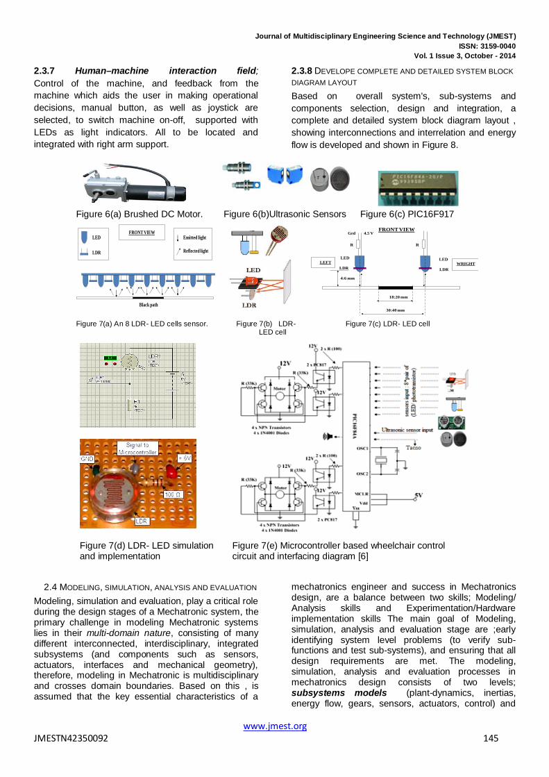
designs, and because of their versatility, Microcontrollers add a lot of power, control, and options at little cost; capable of storing and running programs, also meeting requirements (of space saving, integration, processing power, unit cost, cost of final product, programming language). The optimal microcontroller is PIC16F917, supplied with 5VDC and shown in Figure 6(c), although any PIC with A/D capability would meet this criterion.
2.3.3 Control algorithm selection and design The control unit and control algorithm selections are directly correlated, a variety of controller algorithms that can be used for mechatronic systems including but not limited to : ON-OFF control, P, PI, PD and PID control, intelligent control, Fuzzy control, adaptive control, Neural network control, fuzzy control. Since the control unit is selected to be microcontroller, then microcontroller can be programmed with suitable program-algorithm to achieve desired performance and perform the tasks. Also, suitable, simple, precise, easy to program and implement, control algorithm for wheeled mobile output speed (motion) control could be PID controller and Proportional-Integral (PI) controller with deadbeat response. because of its simplicity and ease of design, PI controller is widely used in variable speed applications and current regulation of electric
1 Backrest 10 Anti-Tip Casters
2 Rear Axle 11 Anti-Tip Casters
3 Rear Wheels 12 Breaks
4 Handrims 13 Tipping Levers
5 Seat: 14 Seatbelts:
6 Frame 15 Push Handles
7 Traverse bar 16 Upholstry
8 Front Rigging 17 Armrests
9 Front Casters 18 Metal Skirt
www.jmest.org JMESTN42350092 142

Journal of Multidisciplinary Engineering Science and Technology (JMEST) ISSN: 3159-0040
Vol. 1 Issue 3, October - 2014
motors. A simplified algorithm for a PI and PID control implementation loop is given below [5-7]. Also selected control unit can be programmed to switch on or off the actuators’ drives, based on inputs’ state (from sensors).
Read KP, KI, KP
previous_error = 0;
integral = 0;
Read target_position / the required position of robot center.
while ( )
Read current_position; //the current position of robot center with respect to the line.
error = target_position – current_position ; // calculate error
proportional = KP * error; // error times proportional gain
integral = integral + error*dt; //integral stores the accumulated error
integral = integral* KI;
derivative = (error - previous_error)/dt; //stores change in error to derivate, dt is sampling period
derivative = KD *derivative;
PID_action = proportional + integral + derivative;
//To add PID_action to the left and right motor speed.
//The sign of PID_action, will determine the direction in
// which the motor will turn.
previous_error =error; //Update error
end
2.3.4 ACTUATORS SUB-SYSTEM SELECTION, SIZING AND INTEGRATION
Actuator converts an information signal from the control unit, into energy acting on the basic system, it is the hardware device that physically carry out the control actions .In mechatronic systems, the actuator runs a certain kind of mechanical-dynamic load process, this can be a position, speed, acceleration, heat, pressure, flow, torque (force), power or a combination. Two types of actuators: motion generator and speaker are to be selected, speaker is actuator used to sound corresponding sounds (Doaa).The accurate control of motion is a fundamental concern in mechatronics applications, where placing or moving an object in the exact desired location or with desired speed with the exact possible amount of force and torque at the
correct exact time, while consuming minimum electric power, at minim cost, is essential for efficient system operation. Motion control is a sub-field of control engineering, in which the position or velocity of a given machine are controlled using some type of actuating machine. The actuating machines most used in mechatronics motion control systems are DC machines (motors). There are many DC machines that may be more or less appropriate to a specific type of application each has its advantages, limitations and disadvantages; electric motors are characterized with excellent performance in motion control, due simple principle of working, quick instantaneous and accurate torque generation, also are capable of generating high torque at low speed, can operate efficiently over a greater range of speeds, as well as, ease of designing and implementing controller to achieve optimal instantaneous, precise, comfortable, smooth and safe motion control performance with low cost and in most cases are reversible. Based on user and system requirements to meet the demand specifications, the suitable actuator selection is brushed DC motor, Wheelchair uses two commercially available brushed DC Motors, shown in Figure 6(a), its specifications and features include; Motor Size: 71mm, , Power: 100W, 150W, 2 Poles, 4 Poles., Supplied Voltage = 12V DC ~ 36V DC, Speed 800 ~ 5000rpm, Operation Mode S1. Actuator placement and integration : As shown in Figure 4, the integration of components results from designing the mechatronics system as an overall system, and embedding sensors, actuators, and microcomputers into the mechanical process, corresponding to this and referring to Figure 4, to physically integrate mechatronics system components,( mechanical structure, sensors, actuators, electronic, microcomputers), the selected actuator is embedded within mechanical structure design and to be located beneath wheelchair seat, connected through gears to wheel. a speaker is to be integrated in mechanical design, near user head.
2.3.5 SENSOR SUB-SYSTEM SELECTION, DESIGN AND INTEGRATION Sensors converts a state variable of the basic system, into an information signal to the control unit. The proposed design requires three types of sensors; a) line sensor for path detection, is one that will gather information about the position of a path, and in turn, generate signal send to controller, b) obstacle detection sensor, to gather and provide a maximum information about path traced, and obstacles in front,c) speed sensor to measure output speed. Based on user and system requirements, morphological table analysis, and selecting best solution, the following sensors are selected:
2.3.5.1 Ultrasonic proximity sensor: Ultrasonic sensors, shown in Figure 6(b), are commonly employed for a wide variety of non-contact, in the air
www.jmest.org JMESTN42350092 143

Journal of Multidisciplinary Engineering Science and Technology (JMEST) ISSN: 3159-0040
Vol. 1 Issue 3, October - 2014
presence, proximity, or distance measuring applications, since they not only detect objects, but they can also indicate and evaluate the absolute distance between themselves and the target. Changing atmospheric conditions such as temperature are compensated during evaluation of measurement. These devices typically transmit a short burst of ultrasonic sound toward a target, which reflects the sound back to the sensor. The system then measures the time for the echo to return to the sensor and computes the distance to the target using the speed of sound in the medium.
2.3.5.2 Sensor Algorithm: The smart wheelchair uses obstacle detection and line sensors to detect presence of an object and the path (black line), the control unit decides the next move according to readings from these sensors based on a given algorithm. Ultrasonic sensor example algorithm is given below: the safe distance to stop the wheelchair, if an object presence in the front, is 25 cm,
Step 1: Read : distance to object.
Step 2: If distance > 50 cm
Move, or , keep velocity of 0.5 m/sec
elseif 40 cm < distance <= 50 cm
Decrease velocity to 0.3 m/sec
elseif 25 cm < distance <= 40 cm
Stop all motions
Step 3 : Go to step 1
2.3.5.3 LDR-LED based line sensor: the predetermined path to track is chosen to be black line over white background. To detect, recognize and track this path, the suitable sensor selection is LDR-LED based line sensor, assembled together in pairs, (as shown in Figure 7), this selection is done because it available, inexpensive, simple, easy to built, interface, and can be easily adapted to many different environments, the main disadvantage of this sensor is, it's slow response to light intensity changes. A line sensor array is designed to be composed of 8 cells, each cell is composed of a LED sender and a LDR receiver (see Figure 7(b)). The sender sends,(emits) light that shall be reflected by the path or surroundings, the receiver receives the reflected light and in response generate signal send to controller. as shown in Figure 7, each LDR circuitry is designed as a voltage divider circuit, the desired resistor value should provide a voltage that covers the on and out black line path conditions, the output of the sensor circuit is an analogue voltage that is used as an input to the control unit (e.g. microcontroller, PIC).
2.3.5.4 Speed sensor (Tachometer); for achieving the desired motion performance of wheelchair, in particular, smooth driving for comfortable riding and
minimum kicks, the required optimal output linear velocity of the wheel chair is selected to be 0.05 M/s, a suitable, inexpensive, available and easy to interface sensor used to measure the actual output motor angular speed, ωL is Tachometer. Sensors placement and integration (as shown in Figure 4): To physically integrate system's hardware components, the selected sensors to detect the path must not be too high nor too low above the surface and to be located on the base of the wheelchair to provide protection against obstacles at close range, the light or color sensor must be far enough in front of the wheels (but not too far) so that it is able to discover a deviation in the line soon enough, so that the robot can adapt in time. Sensors to detect obstacles to be located on the front side of the wheelchair. Tachometer is to be integrated through coupling with electric motor shaft.
2.3.6 SIGNAL CONDITIONING AND INTERFACING SELECTION, DESIGN AND INTEGRATION: Selecting sensors and actuators is followed by selecting and integrating of power supplies, drive, and signal processing conditioning circuits, in order to interface the system components. In this stage, Power supplies, amplifiers, analog signal conditioning circuits, converters DAC, ADC,and power transistors are selected in order to match the sensor, controller and actuators specifications and ratings. The drive is the link between the controller and actuator, the drive main job is to translate the low energy reference signals from the controller, (e.g. Microcontroller, PC, PIC), into high energy power signals to the actuator (e.g. Electric motor). Sensors' (tachometer, line and obstacle detection) outputs are inputted to the microcontroller, the selected microcontroller type is supported with ADC pins, to convert the input analog sensors’ readings to digital value. Depend on the inputs state, the outputs conditions that controll the drive circuit are provided by (C+) software, and correspondingly the motion of smart mobile robot. A voltage regulator (e.g. IC UA723chip) is to be used to regulate the supply voltage (12 V) lowered to a level suitable for use in microcontroller (5.5V), charge controller, LDR-LED sensors and other sensors. a heat sink is to be used to dissipate the heat generated by the long duration used. Different drives can be used including: Relay, H-Bridge and IC’s. The H-bridge circuit is supplied with 12VDC and the four bits outputs of microcontroller to drive the desire conditions of electric Motor. Four NPN Power transistors are used as switch to choose the direction of current flows to the Motor , and correspondingly control the motions of wheelchairclockwise and counter clockwise direction. A common carrier is to be used to assemble and integrate all interface-circuits, electronic components, and control unit in overall design. A simplified version of smart wheelchair circuits, including main conditioning and interfacing is shown in Figure 7(e).
www.jmest.org JMESTN42350092 144
Journal of Multidisciplinary Engineering Science and Technology (JMEST) ISSN: 3159-0040
Vol. 1 Issue 3, October - 2014
2.3.7 Human–machine interaction field; Control of the machine, and feedback from the machine which aids the user in making operational decisions, manual button, as well as joystick are selected, to switch machine on-off, supported with LEDs as light indicators. All to be located and integrated with right arm support.
2.3.8 DEVELOPE COMPLETE AND DETAILED SYSTEM BLOCK DIAGRAM LAYOUT Based on overall system's, sub-systems and components selection, design and integration, a complete and detailed system block diagram layout , showing interconnections and interrelation and energy flow is developed and shown in Figure 8.
Figure 7(d) LDR- LED simulation and implementation
Figure 7(e) Microcontroller based wheelchair control circuit and interfacing diagram [6]
2.4 MODELING, SIMULATION, ANALYSIS AND EVALUATION Modeling, simulation and evaluation, play a critical role during the design stages of a Mechatronic system, the primary challenge in modeling Mechatronic systems lies in their multi-domain nature, consisting of many different interconnected, interdisciplinary, integrated subsystems (and components such as sensors, actuators, interfaces and mechanical geometry), therefore, modeling in Mechatronic is multidisciplinary and crosses domain boundaries. Based on this , is assumed that the key essential characteristics of a
mechatronics engineer and success in Mechatronics design, are a balance between two skills; Modeling/ Analysis skills and Experimentation/Hardware implementation skills The main goal of Modeling, simulation, analysis and evaluation stage are ;early identifying system level problems (to verify sub-functions and test sub-systems), and ensuring that all design requirements are met. The modeling, simulation, analysis and evaluation processes in mechatronics design consists of two levels; subsystems models (plant-dynamics, inertias, energy flow, gears, sensors, actuators, control) and
Figure 6(a) Brushed DC Motor. Figure 6(b)Ultrasonic Sensors Figure 6(c) PIC16F917
LED
LDR
Black path
FRONT VIEWEmitted light
Reflected light
LDR
LED
R
Grd 4.5 V
LDR
LED
R
30:40 mm
18:20 mm
4:6 mm
FRONT VIEW
LEFT WRIGHT
Figure 7(a) An 8 LDR- LED cells sensor. Figure 7(b) LDR-
LED cell Figure 7(c) LDR- LED cell
www.jmest.org JMESTN42350092 145

Journal of Multidisciplinary Engineering Science and Technology (JMEST) ISSN: 3159-0040
Vol. 1 Issue 3, October - 2014
overall system model with various sub-system models interacting similar to real situation, all engineering subsystems should be included in overall system model: mechanical, electrical and electronic components.
It is important that changes in the mechanical structure and other subsystems be evaluated simultaneously; a badly designed mechanical system will never be able to give a good performance by
adding a sophisticated controller, therefore, Mechatronic systems design requires that a mechanical system, dynamics and its control system structure be designed as an integrated system and correspondingly modeled and simulated to obtain unified model of both, that will simply the analysis and prediction of whole system effects and performance. Briefly, in this step, the sub-functions to be verified and the sub-systems models and the whole system model are to be tested and analyzed, to check whether the given design specifications are satisfied.
2.4.1 SUB-SYSTEMS MODELING 2.4.1.1 Subsystems modeling (Actuator, Sensor, Plant-dynamics, inertias, energy flow, gears, control algorithm subsystems modeling)
2.4.1.1 Actuator sub-system modeling The motion control of the proposed mobile robot design, in the form of smart wheelchair, is simplified to an electric machine (DC motor) motion control, the simplest and widespread approach to control the mobile robot motion is the differential drive style.There are many motor motion control strategies that may be more or less appropriate to a specific type of application, each has its advantages, limitations and disadvantages, the designer must select the best electric machine (motor) and corresponding motion control strategy for specific application and desired overall response. The most basic design requirements of a given electric DC machine are to rotate at desired angular speed ω =dθ/dt and to achieve desired angular position, θ , at the minimum possible steady-state error ess , also the motor must accelerate to its steady-state speed, α=d2θ/dt2 as soon as it turns on, this means it is desirable to have a minimum suitable settling time , Ts that will not damage the equipment ( e.g. Ts in less than 2 sec), and the minimum suitable overshoot, Mp ( e.g. Mp less than 5%). Motors sizing: it is to specify, preferably, motor and drive combination that can provide the torque, speed and acceleration as required by the mechanical set, proper motor sizing will not only result in significant cost savings by saving energy, reducing purchasing and operating costs, reducing downtime, etc., it also helps the engineer to select and design better motion control systems. Motor constant, Km is the most convenient figure of merit for sizing DC motors for any
motion control application. Km defines the ability of the motor to transform electrical power to mechanical power. Physically, Km represents the available torque T per square-root watt of input power in Watt ; and given by: /mK T P= Where: The load torque and
power supply are normally specified. P = I 2 R .the power dissipated by the motor. T= Kt *I, Peak torque at Vp, R : armature resistance. Kt : Torque constant, I: armature current, Km and Kt ,can relate by substituting P = I 2 R and T= Kt *I, this gives:
/m tK K R= .
The actuator, the DC motor, is an example of electromechanical systems with electrical and mechanical components, a simplified equivalent representation of PMDC motor's two components are shown in Figure 9(a) .The equations of motion for the wheelchair-robot will consider the simple case of single-degree-of freedom motion, moving forward and reverse. A simplified model of a symmetric half of system is constructed as shown in Figure 9(b) and to be used to write the equivalent model.
mm
Electromechanical PMDC motor system
MECHANICAL component of PMDC motor systemELECTRIC component of PMDC motor system
Figure 9(a) Schematic of a simplified equivalent representation of the PMDC motor's electromechanical components
Gear
DriveBattery
Control
Ref.
El.MotorWheel
Tacho.V.R.
Figure 9(b) A simple model of half of the wheelchair
Different researches on modeling, simulation, analysis and motion control of electric motors and mobile robots, can be found in different texts, including [6-13] Referring to Figure 9(a)(b), applying a voltage to motor coils produce a torque Tm in the armature, the torque
www.jmest.org JMESTN42350092 146

Journal of Multidisciplinary Engineering Science and Technology (JMEST) ISSN: 3159-0040
Vol. 1 Issue 3, October - 2014
developed by the motor is related to the armature current, ia by a torque constant, Kt and given by Eq.(1).The back electromotive force, EMF voltage, ea is induced by the rotation of the armature windings in the fixed magnetic field. The EMF is related to the motor shaft angular speed ,ωm by a linear relation given by Eq.(2).Equation that describes the electrical characteristics of DC motor is obtained applying Kirchoff’s law around the electrical loop (Figure 9(a)), this gives Eq.(3).The torque, developed by motor, produced an angular velocity, ωm = dθm /dt, according to the inertia J and damping friction, b, of the motor and load. Performing the energy balance on the DC motor system, equation that describes the mechanical characteristics of DC motor is obtained and given by Eq.(4). Based on derived equations and manipulating,the PMDC motor open loop transfer function without any load attached relating the input
voltage, Vin(s), to the shaft output angular velocity, ω(s), is given by Eq.(5):
State space representation of DC motor open loop sub-system: The state variables (along with the input functions) used in equations describing the dynamics of a system, provide the future state of the system. Mathematically, the state of the system is described by a set of first-order differential equation in terms of state variables. The state space model takes the below form, rearranging Eq.(3) and Eq.(4) to have the two first order equations given by Eqs. (6)(7), relating the angular speed and armature current. Looking at the DC motor position θ, as being the output, and choosing the state variable position θm, velocity ωm and armature currents ia, Substituting state variables, for electric and mechanical part equations rearranging gives Eq.(7b). Looking at DC motor speed, as being the output, the state space model given by Eq.(8), is obtained
Motor Torque = Tm = Kt* ia (1) ( ) * ( ) /a b m b me t K d t dt Kθ ω= = (2)
( ) ( ) ( )( ) ( )( ) ( ) ain a a a b a a in b
di t d tV R i t L K L s R I s V s K s sdt dt
θ θ = ∗ + + ⇔ + = −
(3)
( ) ( ) ( ) ( ) ( )2* * – * 0 ( )t m m t m mK I s J s s b s s K I s J s b s sθ θ θ− = ⇔ = + (4)
( )( ){ } 2
( )( )( ) ( ) ( ) ( )
t tspeed
in a m a m m a a m t ba a m m t b
K KsG sV s L J s R J b L s R b K KL s R J s b K Kω
= = = + + + ++ + +
(5)
[ ] [ ]
01
1 0 01
tm
m min
b aa aa
a a
in
KbJ Jd VK Rdt i i LL L
V
θ θ
θθ
− = + − −
= +
(8)
dx Ax Budty CX Du
= +
= +
t a m L
m m m
K i b Tddt J J J
ωω ∗ ∗= − − (6)
a a a b in
a a a
di R i K Vdt L L L
ω∗ ∗= − − − (7)
1
2
3 a
xdxdt
x i
θθ
=
= ⇔
=
'1 2
2'2 2
'3
t a m L
m m m
a a a b in
a a a
dx xdt
K i b Td dxdt J J Jdt
di R i K Vx
dt L L L
θ
ωθ ω
ω
= =
∗ ∗= = = − − ⇔
∗ ∗= = − − −
'1 2
2'2 2
'3
t a m L
m m m
a a a b in
a a a
dx xdt
K i b Td dxdt J J Jdt
di R i K Vx
dt L L L
θ
ωθ ω
ω
= =
∗ ∗= = = − −
∗ ∗= = − − −
(7b)
www.jmest.org JMESTN42350092 147

Journal of Multidisciplinary Engineering Science and Technology (JMEST) ISSN: 3159-0040
Vol. 1 Issue 3, October - 2014
2.4.1.2 WHEELS, GEARS AND INERTIAS MODELING
The geometry of the mechanical part determines the moment of inertia, the wheelchair platform can be considered to be of the cuboid shape (Figure 10), with the inertia calculated as given by Eq.(9), where the total equivalent inertia, Jequiv and total equivalent damping, bequiv at the armature of the motor with gears attaches, are given by Eq.(9): The inertias of gears and wheels have to be included in the calculations of total equivalent inertia, and calculated as given by Eq.(10) . Referring to Figure 11, the output linear velocity of wheelchair equals to the linear velocity of any given point on the outer circumference of the wheel, therefore: the speed of wheelchair is equal to the circumference of the wheels multiplied by speed of wheels turning, and given by Eq.(11), where: RPM= RPS *60. Wheel circumference=2πr. The relation between RPM and angular velocity is given by Eq.(12). The angular velocity in terms of RPM is given by Eq.(13). Finally, based on derived equations, the primary equivalent mobile robot system open loop transfer function with load and gears attached, in terms input voltage, Vin(s), to output shaft angular velocity, ω(s), is given by Eq. (14):
2
1
2
2
1
2
3
12
equiv m Load
equiv m Load
load
Nb b bN
NJ J JN
bhJ
= +
= +
=
(9)
( )221 2( )* /equiv motor gear wheelJ J J J mr N N= + + + (10)
V wheelchair = wheel circumference * RPS (11)
/sec260rad RPM πω =
(12)
30
RPMπω= (13)
wheelchairV wheel circumference * SDistance travelled per minute = x RPM x S x 60π π
==
=
2
( ) /( )( ) ( ) ( ) ( )
robot t
in a equiv a equiv equiv a a equiv t b
s K nG sV s L J s R J b L s R b K Kω
= = + + + +
(14)
Force required per wheel
Wheel radius
Wheel rotation
Figure 11(a)
rωr: Radius, ω: angular velocity V: Linear velocity,
V = ω * r
Figure 11(b)
Figure 11(a)(b) The output linear velocity of wheelchair.
2.4.1.3 SENSORS SUB-SYSTEM MODELING Tachometer is a sensor used to measure the actual output mobile robot angular speed, ωL .. Dynamics of tachometer can be represented using Eq.(15) . The transfer function of the tachometer is given by Eq.(16), since it was chosen to drive system, with linear velocity of 0.5 ms the required angular speed is obtained as given by Eq.(17), therefore, the tachometer constant, Ktac for ω = 6.6667 , is given as by Eq.(18):
( ) ( ) ( ) * / * out tac out tacV t K d t dt V t Kθ ω= = = (15)
( ) ( )/out tacV s s Kω = (16)
/ 0.5/0.075 6.6667 rad / s,V rω = = = (17)
( ) / (t) =12/6.6667 1.8outtac VK t ω= = (18)
2.4.1.4 System’s dynamics modeling When deriving an accurate mathematical model for mobile platform system, it is important to study and analyze dynamics between the road-surface, wheel and platform and considering all the forces applied upon the mobile platform system. Several forces are acting on mobile platform when it is running, the modeling of a mobile platform system dynamics involves the balance among the acting on a running platform forces, these acting forces are categorized into road-load and tractive force. The road-load force consists of the gravitational force, hill-climbing force, rolling resistance of the tires, the aerodynamic drag force and the aerodynamics lift force, where aerodynamic drag force and rolling resistance is pure losses, meanwhile the forces due to climbing resistance and acceleration are conservative forces with possibility to partly recover. The resultant force is the sum of all these acting forces, will produce a counteractive torque to the driving motor, i.e., the tractive force. Figure 12
Figure 10 wheelchair inertias and Gear ratio Motor
WheelGear ratio, G
www.jmest.org JMESTN42350092 148

Journal of Multidisciplinary Engineering Science and Technology (JMEST) ISSN: 3159-0040
Vol. 1 Issue 3, October - 2014
shows that, changes in the road-surface inclination angle, α is a disturbance introduced to the system, therefore it is required to design controller to be robust and should have a disturbance rejection. The disturbance torque to mobile platform is the total resultant torque generated by the acting forces.
Rolling resistance force, Frolling, and rolling resistance torque are given by Eq.(19), where: M-The mass of the mobile platform and passenger (Kg). G: The gravity acceleration (m/s2). ν: the mobile platform linear speed, Cr0 the friction coefficient for wheel mechanism that accounts for friction in the wheel, bearings and other speed-dependent retarding torques.
( )
rolling _ r r
rolling r
F *C * *C *cos( )
T * *C *cos( ) *normal force
r
F M g
M g r
a
a
= =
= (19)
Aerodynamic Drag force , Faerod the force opposing the motion of the vehicle due to air drag, wind resistance, Faerod , and the aerodynamics torque are given by Eq.(20),:
( )2
aerod d
2aerod d
F 0.5* *A*C *
T 0.5* *A*C * *vehicl
robot rr
r υ
r υ
=
= (20)
The hill-climbing resistance force Fclimb; While the mobile platform is moving up or down a hill, the weight of the mobile platform will create a hill-climbing resistance force directed downward, this force will oppose or contribute to the motion, Fclimb and torque are given by(21):
( )
climb
climb slope
F * *sin( )F = * *sin( ) * wheel
M gT M g r
aa
=
= (21)
The angular acceleration force Facc_angle , is the force required by the wheels to make angular acceleration is given by Eq.(22), The angular acceleration torque is given byEq.(23):
2
acc_ angle 2Fwheel
GJ ar
= (22)
2 2
acc_ angle 2*wheelwheel wheel
G GT r J a J ar r
= = (23)
The needed energy of mobile platform, the requested power in kW that mobile platform must develop at stabilized speed can be determined by multiplying the total force with the velocity of the platform, as given by Eq.(24):
( ) * *Total TotalP F Fυ υ= ∑ = (24)
Substituting derived dynamic equations and applying the total torque to electric motor equation, will result in
mathematical model of mobile platform dynamics, given by (25)
α
M*g
Road incl.
r =ν/ω
Figure 12 Forces acting on moving mobile robotic platform [7].
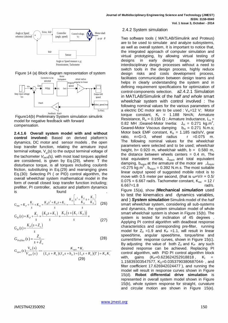
2.4.1.5 control algorithm-subsystem modeling Since embedded Microcontroller is selected to be the optimal selection for control unit, Microcontroller can be programmed to read sensors and in turn, according to written program, control the performance of overall system including, controlling the drive that in turn control the actuator to achieve and maintain both desired performance and speed in accordance with requirements. A suitable control algorithm for wheelchair mobile motion control could be PID controller or PI algorithm with deadbeat response. An example of PID and sensor algorithm program for Microcontroller programming is listed in 2.3.3 and 2.3.5.2. . PID control algorithm is given by Eq.(26), where the sign of the controller’s output, will determine the direction in which the motor will turn. Because of its simplicity and ease of design, PI control algorithm given by Eq.(27) is widely used in variable speed applications and current regulation of electric motors. Deadbeat response means the response that proceeds rapidly to the desired level and holds at that level with minimal overshoot[8]. The characteristics of deadbeat response include; Zero steady state error, Fast response, (short rise time and settling time) and minimal undershoot, ±2% error band.PI controller represents a pole located at the origin and a stable zero placed near the pole, at Zo=- KI/ KP, resulting in drastically eliminating steady state error due to the fact that the feedback control system type is increased by one. The PI pole and zero will affect the response, mainly the PI zero, Zo=- KI/ KP, will inversely affect the response and should be cancelled by prefilter, therefore the required prefilter transfer function to cancel the zero is given by Eq.(28). A negative closed loop feedback control system with forward controller and corresponding System simulation ( used toto test the system’s response to different inputs ) simulink model shown in Figure 14 (a)(b) are to be used, to design and test the design of controller.
www.jmest.org JMESTN42350092 149
Journal of Multidisciplinary Engineering Science and Technology (JMEST) ISSN: 3159-0040
Vol. 1 Issue 3, October - 2014
Controller(angle, speed)
Control voltage, Vc
Angle or Speed measure e,.g Potentiometer, Tachometer
Sensor
+-
Error, VoltAngle or Speed reference (desired)
Volt
Motor shaft
ω or θ
Figure 14 (a) Block diagram representation of system
ErrorAngular
speed
Vtach
Vinr
wheel radius angular to l inear
-K-
feedback , Ktach
Robot_speed.mat
To File1
Step input voltageVin
Output shftspeed
In1 Out1
MotorSubsystem
PID(s)
Controller to be selected
Figure14(b) Preliminary System simulation simulink model for negative feedback with forward compensation.
2.4.1.6 Overall system model with and without control involved: Based on derived platform’s dynamics, DC motor and sensor models , the open loop transfer function, relating the armature input terminal voltage, Vin(s) to the output terminal voltage of the tachometer Vtach(s), with most load torques applied are considered, is given by Eq.(29), where: T the disturbance torque, is all torques including coulomb friction, substituting in Eq.(29) and rearranging gives Eq.(30): Selecting PI ( or PID) control algorithm, the overall wheelchair system mathematical model in the form of overall closed loop transfer function including; prefilter, PI controller, actuator and platform dynamics is found .
22
P ID
D DI D P IPID P D
K KK s sK KK K s K s KG K K
s s s
+ + + + = + + = = (26)
( ) ( )( )
( )
/( )
( )
P I PP IIPI P
P oPI
K s K KK s KKG s Ks s s
K s ZG s
s
++= + = = =
+=
(27)
Pr ( ) oefilter
o
ZG ss Z
=+
(28)
( )( ) ( ) ( )( )
inV s *( )
( )tach t
opentach a a m m a a b t
K KG s
V s L s R J s b L s R T K K==
+ + + + +
(29)
2.4.2 System simulation
Two software tools ( MATLAB/Simulink and Proteus) are to be used to simulate and analyze subsystems, as well as overall system, It is important to notice that, the integrated approach of computer simulation and virtual prototyping, by allowing virtual testing of designs in early design stage, integrating interdisciplinary design processes without a need to switch tools in the design process, highly reduce design risks and costs development process, facilitates communication between design teams and helps in clearly understanding the system and in defining requirement specifications for optimization of control-components selection. a2.4.2.1 Simulation in MATLAB/Simulink of the half and whole smart wheelchair system with control involved : The following nominal values for the various parameters of a electric DC motor are to be used : Vin=12 V; Motor torque constant, Kt = 1.188 Nm/A; Armature Resistance, Ra = 0.156 Ω ; Armature Inductance, La = 0.82 MH ;Geared-Motor Inertia: Jm = 0.271 kg.m2, Geared-Motor Viscous damping bm = 0.271 N.m.s; Motor back EMF constant, Kb = 1.185 rad/s/V, gear ratio, n=G=3, wheel radius r =0.075 m. The following nominal values for the wheelchair parameters were selected and to be used; wheelchair height, h= 0.920 m, wheelchair width, b = 0.580 m, the distance between wheels centers = 0.4 m, The total equivalent inertia, Jequiv and total equivalent damping, bequiv at the armature of the motor are ,Jequiv =0.275 kg.m2 , bequiv = 0.392 N.m.s. The most suitable linear output speed of suggested mobile robot is to move with 0.5 meter per second, (that is ω=V/r = 0.5/ 0.075 = 6.667 rad/s. Tachometer constant, Ktac = 12 / 6.667=1.8 rad/s. Figure 15(a), show (Mechanical simulation used to test the kinematics and dynamics variables, and ) System simulation Simulink model of the half smart wheelchair system, considering all sub-systems and dynamics, the system simulation model of whole smart wheelchair system is shown in Figure 15(b). The system is tested for inclination of 45 degrees . Applying PI control algorithm with deadbeat response characteristics and corresponding pre-filter, running model for Z0 =1.9 and KP =1.1, will result in linear speed/time, angular speed/time, torque/time and current/time response curves, shown in Figure 15(c). By adjusting the value of both Z0 and KP any such desired response can be achieved. Replacing PI control algorithm, with PID PI control algorithm block with, gains (KP= 0.623624252918818 , KI = 1.15839303547577, KD= -0.0353790380687044 , and filter coefficient 17.626942024477 ), and running the model will result in response curves shown in Figure 15(d). Robot differential drive simulation is represented in overall system model shown in Figure 15(b), whole system response for straight, curvature and circular motion are shown in Figure 15(e).
www.jmest.org JMESTN42350092 150

Journal of Multidisciplinary Engineering Science and Technology (JMEST) ISSN: 3159-0040
Vol. 1 Issue 3, October - 2014
2 2 2
2 *( )
2 2 2 2 2tach t
openequiv a a equiv a a r a equiv a b t r a equiv a
K KG s
b L s r ML s b R s r MR s C L s J L s K K C R J R=
+ + + + + + + + (30)
mobile robot angular speed
,iTorque
EMF constant Kb
PI Controller
Kt
torqueconstant
-K-
speedfeedbacK
-K-
rad2mpsV=W*r
-K-
r^2m/2
-K-
r*m*g/2 , correct
l inear, speed m/s
linear speed1
1/n
gear ration=3.
angualr_spped
1
La.s+Ra
Transfer function1/(Ls+R)
1
den(s)
Transfer function1/(Js+b)
Torque in N/m
Torque
Mobile_robot4.mat
To File..5
Mobile_robot.mat
To File..1
Step,V=12,
Kb
sin(u)cos(u)
SinCos
Out1
Profile input_1
Out1
Prfi le input_2
Zo
s+ZoPrefilter
45
Inclination angle
du/dt
Derivative
CurrentControl signal
Angular speed , rad/sec
s+Zo
s,
Mobile_robot3.mat
v
Mobile_robot2.mat
2
-K-
'
Kp
Figure 15(a) System simulation Simulink model of half wheelchair.
V
W
Mobile robot Turning Radius
m/s
m
m/s
m
W=
-K-
speed angle feedbacK2
-K-
speed feedbacK3
XY Graph
W_Robot
V_right wheel
V_left wheel
V_Robot
Switch
Out1
Subsystem2
Out1
Subsystem1 S_lef t
S_right
V_Robot
X
Y
Subsystem
Saturation1
Saturation
Uin
Wheel Velocity
Wheel Position
Right Motor+Wheel.
R_Robot
PID(s)
PID Controller2
PID(s)
PID Controller1
Uin
Wheel Velocity
Wheel Position
Left Motor+Wheel
[V]
Goto
-K-
Gain,
0.5
Gain
[V]
From
Divide
10
Constant1
Figure 15(b) System simulation Simulink model of overall wheelchair system [7-8]
0 2 4 6 80
2
4
6
8
Time (seconds)
Rad
/sec
Angular speed/time
0 2 4 6 80
0.2
0.4
0.6
0.8
Time (seconds)
M/s
Linear speed/time
0 2 4 6 80
1
2
3
4
Time (seconds)
Am
p
Current/time
0 2 4 6 80
2
4
6
Time (seconds)
Nm
Torque/time
0 5 100
2
4
6
8
Time (seconds)
Rad
/sec
Angular speed/time
0 5 100
0.2
0.4
0.6
0.8
Time (seconds)
M/s
Linear speed/time
0 5 10-5
0
5
10
Time (seconds)
Am
p
Current/time
0 5 10-5
0
5
10
Time (seconds)
Nm
Torque/time
Figure 15(d) linear speed/time, torque/time, angular speed/time and current/time response curves of the accurate close loop mobile robotic platform model with PID controller.
Figure 15(c),. Linear speed/time, torque/time, angular speed/time and current/time response curves of medium mobile robots model with PI controller with deadbeat response.
www.jmest.org JMESTN42350092 151

Journal of Multidisciplinary Engineering Science and Technology (JMEST) ISSN: 3159-0040
Vol. 1 Issue 3, October - 2014
(a)
(b)
(c)
Figure 15(d) Three different trajectories of the central point of the mobile robot.
2.4.2.2 ELECTRONIC SIMULATION IN PROTEUS SOFTWARE
To test and evaluate the selection, electric/electronic circuits, components design, interfaces , and programming of each of microcontroller, software, electronics, H-bridge and/or L93D IC, transistors, sensors, PWM signal and motor speed, the system with all components can be simulated using ISIS-Professional Proteus, The control program written in C, with the help of MikroC program is converted to Hex. File and downloaded on the simulated PIC-microcontroller and circuit, the electronic simulation is shown in Figure 16, after testing, evaluating and optimizing various aspects, the final simulation results show the correctness of written program, interfaces, components, and microcontroller, all these subsystems and components can be integrated to build the optimal physical system
Figure 16(a) electronic Simulation of controlling DC motor driver IC L293D
FIGURE 16(B)OVERALL SYSTEM ELECTRONIC SIMULATIONS IN PROTEUS
2.4.3 ANALYSIS AND EVALUATION The sub-functions to be verified and the subsystems models and the whole system model, are to be tested and analyzed, Applying (PI) controller with deadbeat response, several observations can be made, first, for 12 V input, the wheelchair system will reach output angular speed of 6.67 rad/s that is 0.5 m/s in about 2 s,. Second, the mobile wheelchair system draws about 7.8 Amp, peak and about A continuous in operation. The response curve shows achieving smooth driving for comfortable riding and no kicks (overshoots), the system take suitable time (2 seconds) to reach desired output linear speed, the system is robust against disturbance, all design and user requirements are met. If the design specifications are still not met, simple modifications to the control components and algorithms should be attempted. If further improvements are needed to satisfy the performance requirements, more sophisticated control techniques and algorithms should be implemented. If the problems persist, we may want to return to the previous step and change the system components or even modify the control system structure. If the performance is still not satisfactory, we should seriously consider replacing or redesigning the plant itself and repeating the design steps outlined above [1-2][14]. After verifying the required system design through computer simulation, the given numerical
www.jmest.org JMESTN42350092 152

Journal of Multidisciplinary Engineering Science and Technology (JMEST) ISSN: 3159-0040
Vol. 1 Issue 3, October - 2014
values for whole system and components simulation, particularly, wheelchair dimensions, weight, gear ratio, wheel radius, DC motor parameters, speed sensor, all these components can be acquired in order to assemble-integrate the required system.
2.5 PROTOTYPING, TESTING, EVALUATION AND OPTIMIZATION As noted, there is no single model which can ever flawlessly reproduce reality. There will always be errors called as unmodeled errors between behavior of a product model and the actual product. In order to take into account the unmodeled errors and enhance precision, performance in the design process, the mechatronics design approach includes prototyping phase. A prototype is models used to test, evaluate and optimize various aspects of a new design to enhance precision, performance and gather early user feedback. Prototyping is putting together a working model, serves to provide specifications for a real, working system rather than a theoretical one, it is believed to reduce project risks and cost. Prototyping development may be carried out in the following two forms; 1) Virtual Prototype Virtual prototyping is an aspect of information technology that permits analysts to examine manipulate, and test the form, fit, motion, logistics, and human factors of conceptual designs on a computer monitor. 2) Physical Prototype: System integration to ensure components and subsystems work together
2.5.1 Virtual prototyping: beside MATLAB/Simulink, there are many industrial robotics software simulators for 2-3D Modeling and rendering, some has type of robotics software has a simulator that is a "virtual" robot which is capable of emulating the motion of an actual robot in a real work envelope and realistic renderings and movements of the robot in 3D space, examples include RoboLogix and MOBS - Mobile Robot . System simulation in Simulator MOBS is shown in Figure 17[15], a virtual prototype in Simulink and proteus are shown in Figure 15
2.5.2 Physical prototyping: To physically verify the sub-functions and teste and analyze the subsystems and the whole system design, to ensure subsystems, components and whole smart mechatronics Robot-Motawif work together and meet user's needs and requirements, all selected sub-systems and components, were integrated in one first prototype (shown in Figure 18). Testing and evaluation were done under normal operating conditions and for desired performance , at first, smart wheelchair was used to perform main motions in performing Al Omrah at a similar to Alharam Alshareef application environment at Mechatronics Sec. Lab., Taif University, Taif, Saudi Arabia 2012, the shortcomings of designed system are identified, and the corresponding design of
mechatronics sub-system is refined, and some of components and program aspect were redesigned.
2.6 MANUFACTURING AND COMMERCIALIZATION Once the developed system is tested, refined, and confirmed to satisfy the required specifications, the processes of technology transfer to industry and commercialization, could begin. Prepare product’s documents including preparing necessary production and operation structures, infrastructure and an approved business plan and funds, Suitable plans for commercial development and marketing. According to the existing practice, engineers, scientists, and technicians provide minimal input into these activities which is not desirable and needs to be greatly improved [1-2][14].
2.7 SUPPORT, SERVICE AND MARKET FEEDBACK ANALYSIS
The sustained success of products commercial and marketing depends on market feedback analysis and a comprehensive range of user support and service including a highly experienced team of support and service engineers that enables manufacturer to provide a broad spectrum of services including; Consulting sservices, ooperational sservices, aapplication sservices Market feedback analysis is to use objective market data, user satisfaction surveys, interviews, routine interactions and communications, product and service quality and reliability data, to give insight into customers' perspective and expectations of product modifications of design and performance.
Figure 17 MOBS Mobile Robot Simulator [15]
www.jmest.org JMESTN42350092 153

Journal of Multidisciplinary Engineering Science and Technology (JMEST) ISSN: 3159-0040
Vol. 1 Issue 3, October - 2014
Figure 18 Physical prototype of the designed smart Mobile Robotic guidance system –Mechatronics
Motawif, Mechatronics Sec. Lab., Taif University, Taif, Saudi Arabia 2012.
CONCLUSIONS The key element in success of a mechatronics engineering education-program, and correspondingly, Mechatronics engineering graduates, is directly related to the applied structural design methodology. Based on VDI 2206 guideline and different industrial, scientific and educational resources, a mechatronics systems design education-oriented methodology is proposed to fulfill mechatronics optimal program requirements. The proposed methodology consists of a systematic specific simple and clear simultaneous design and integration steps (shown in diagram 1(a)(b)) that can be memorized and followed, as well as support non experienced student or group of students in solving mechatronics design integrated tasks. The design methodology aims to integrate multidisciplinary knowledge, in various stages including pre-study process and problem statement, conceptual design, optimal parallel selection and synergistic integration, modeling, simulation, prototyping, analysis and physical implementations through the design process and development of mechatronics product. In this paper, the proposed mechatronics design methodology is described, discussed and applied with the help of example
student graduate project; design and implementation of mechatronics mobile robotic guidance system in the from of smart wheelchair- Mechatronics Motawif, to help and support people with disabilities and special needs to perform specific predetermined tasks, particularly, performing Al Omrah and motion around holy Kaba, Makka.
REFERENCES [1] Farhan A. Salem Ahmad A. Mahfouz’’ A Proposed Approach to
Mechatronics Design and Implementation Education-Oriented Methodology’’Innovative Systems Design and Engineering, Vol.4, No.10, pp 12-29, 2013.
[2] Mechatronics Design And Implementation Education-Oriented Methodology; A Proposed Approach, Journal of Multidisciplinary Engineering Science and Technology Vol. 1, Issue. 03 , October - 2014
[3] K. Craig, F. Stolfi “Teaching control system design through Mechatronics: academic and industrial perspectives.” Mechatronics, Vol 12, No. 2, pp. 371-381, 2002,
[4] Robert Bishop, Francis C. Moon, Mechatronics systems, sensors and actuators, fundamentals and modeling,( Francis C. Moon, Section II, Physical System Modeling), CRC Press, Tyler and francis group, Newyork, 2008.
[5] Main mechanical descriptions and images were quoted from : http://www.assistireland. ie/ eng/ Information/Information_Sheets/ Choosing_a_Standard_Self-Propelled_Wheelchair.html
[6] Ahmad A. Mahfouz (2012), Ayman A. Aly, Farhan A. Salem, ''Mechatronics Design of a Mobile Robot System'', ,I.J. Intelligent Systems and Applications, .
[7] Ahmad A. Mahfouz (2013), Mohammed M. K. , Farhan A. Salem Modeling, simulation and dynamics analysis issues of electric motor, for Mechatronics applications, using different approaches and verification by MATLAB/Simulink (I). I.J. Intelligent Systems and Applications, .
[8] Richard C. Dorf (2001) Robert H. Bishop, Modern Control Systems 12 Ed, Pearson Education, Inc.,
[9] Thomas R. Kurfess (2005), “Robotic and Automation Handbook,” Washington, D.C., United States of Amarica, .
[10] Mohsen Shahinpoor, (1987) “A Robot Engineering Textbook,”HAPPER & ROW, Publishers, Inc.,10 East 53rd street, New York, NY10022.
[11] Bashir M. Y. Nouri (2005) ,modeling and control of mobile robots Proceeding of the First International Conference on Modeling, Simulation and Applied Optimization, Sharjah, U.A.E. February 1-3, .
[12] Chun Htoo Aung(2008), Khin Thandar Lwin, and Yin Mon Myint, Modeling Motion Control System for Motorized Robot Arm using MATLAB World Academy of Science, Engineering and Technology 42, .
[13] Ramjee Prased, modeling of robotic arm,10804900, Rh680B54,B. TECH (LEET) BCE
[14] L Al-Sharif (2010), A Saleem, and TA Tutunji, Mechatronic system design: The ideal capstone course? 7th International Symposium on Mechatronics and its Applications (ISMA), , also L Al-Sharif "Mechatronics System Design 0908531: Course Notes", Mechatronics Engineering Department, University of Jordan.
[15] University of Western Australia, MOBS, Mobile Robot Simulator; http://robotics. ee.uwa. edu.au/mobs.
www.jmest.org JMESTN42350092 154