mechatronics design and implementation education-oriented ... · pdf filemechatronics design...
TRANSCRIPT
Journal of Multidisciplinary Engineering Science and Technology (JMEST) ISSN: 3159-0040
Vol. 1 Issue 3, October - 2014
Mechatronics Design And Implementation Education-Oriented Methodology; A
Proposed Approach
Farhan A. Salem Mechatronics engineering program, Department of Mechanical Engineering, College of Engineering, Taif University, 888, Taif,
Saudi Arabia. Alpha center for Engineering Studies and Technology Researches, Amman, Jordan. Email:
Ahmad A. Mahfouz Department of Automatic and Mechatronics Systems, Vladimir State University,
Vladimir, RF. Alpha center for Engineering Studies and Technology Researches, Amman, Jordan. Email:
Abstract— Mechatronics engineer is expected to design engineering systems with synergy and integration toward constrains like higher performance, speed, precision, efficiency, lower costs and functionality. The key element in success of a Mechatronics engineering education-program, and correspondingly, Mechatronics engineering graduates, is directly related to a well-structured Mechatronics system design course and the applied structural design methodology. Guidelines for structural design methodology and tools for the development process of Mechatronics products, that can be applied in educational process, support engineering educators and help non experienced student or group of students in solving Mechatronics design tasks, is highly required. This paper extends writer’s previous works and proposes Mechatronics system design education-oriented methodology, which aims to integrate multidisciplinary knowledge, in various stages through the design and development process of Mechatronics product.
Keywords—Mechatronics education, Design methodology, Parallel design, Synergy, Integration, Interdesiplinary .
I. INTRODUCTION The modern advances in information technology and decision making, as well as the synergetic integration of different fundamental engineering domains caused the engineering problems to get harder, broader, and deeper. Problems are multidisciplinary and require a multidisciplinary engineering systems approach to solve them, such modern multidisciplinary systems are called Mechatronics systems, correspondingly, engineers face daunting challenges, and to be competitive, in labor market, engineers must provide high value by being immediate, innovative, integrative, conceptual, and multidisciplinary, engineers must have depth in a specific engineering discipline, as well as multidisciplinary engineering breadth, with a balance between theory and practice, in addition, they must have breadth in business and human values, an engineer with such qualifications is called Mechatronics engineer. Mechatronics engineer is expected to design products with synergy and integration toward constrains like higher performance, speed, precision, efficiency, lower costs and functionality. Also in order to evaluate concepts generated during the design process, without
building and testing each one, Mechatronics engineer must be skilled in the modeling, simulation analysis, and control of dynamic systems and understand the key issues in hardware implementation [1]. Modeling, simulation and evaluation, play a critical role during the design stages of a Mechatronic system, the primary challenge in modeling Mechatronic systems lies in their multi-domain nature, consisting of many different interconnected, interdisciplinary, integrated subsystems (and components such as sensors, actuators, interfaces and mechanical geometry), therefore, modeling in Mechatronic is multidisciplinary and crosses domain boundaries. Engineering educators face daunting challenges, where due to different disciplines involved, the Mechatronics design process may become very complex. The key element in success of a Mechatronics engineering program, and correspondingly Mechatronics engineering graduates, is directly related to the applied structural design methodology. a guidelines for structural design methodology and tools for the development process of Mechatronic products, that can support educators and help students in solving Mechatronics design tasks with their specific properties and can be applied in educational process is highly required. This paper extends writers’ previous work [2] and proposes Mechatronics system design education-oriented methodology, to fulfill Mechatronics optimal program requirements, and aims to support engineering educators and help non experienced student or group of students to integrate multidisciplinary knowledge, in various stages in solving Mechatronics design integrated tasks. There are many definitions of Mechatronics, Mechatronics can be defined as multidisciplinary concept (Figure 1(a)), it is synergistic integration of mechanical engineering, electric engineering, electronic systems, information technology, intelligent control system, and computer hardware and software to manage complexity, uncertainty, and communication through the design and manufacture of products and processes from the very start of the design process, thus enabling complex decision making. Modern products are considered Mechatronics products, since, it is
www.jmest.org JMESTN42350081 34
Journal of Multidisciplinary Engineering Science and Technology (JMEST) ISSN: 3159-0040
Vol. 1 Issue 3, October - 2014
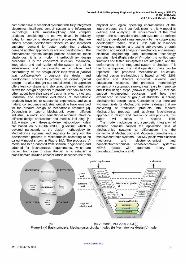
comprehensive mechanical systems with fully integrated electronics, intelligent control system and information technology. Such multidisciplinary and complex products, considering the top two drivers in industry today for improving development processes, that are shorter product-development schedules and increased customer demand for better performing products, demand another approach for efficient development. The Mechatronics system design process addresses these challenges, it is a modern interdisciplinary design procedure, it is the concurrent selection, evaluation, integration, and optimization of the system and all its sub-systems and components as a whole and concurrently, all the design disciplines work in parallel and collaboratively throughout the design and development process to produce an overall optimal design– no after-thought add-ons allowed, this approach offers less constrains and shortened development, also allows the design engineers to provide feedback to each other about how their part of design is effect by others. Industrial and scientific evaluations of Mechatronic products have led to substantial experience, and as a natural consequence industrial guideline have emerged for the product design of Mechatronic products [3]. Depending on type of Mechatronic system, different industrial, scientific and educational recourse introduce different design approaches and models, including: [4-21]. A major role in these guideline methodology models are based on VDI2206 (2003) guideline, which is devoted particularly to the design methodology for Mechatronics systems and suggests to carry out the development process of Mechatronics according to so called V-model shown in Figure 1(b). The proposed V-model has been adopted from software engineering and adapted for Mechatronics requirements, which are distinct from case to case, the aim is to establish a cross-domain solution concept which describes the main
physical and logical operating characteristics of the future product, the input (Left side) to this V-model is defining and analyzing all requirements of the total system, the sub-functions and sub-systems are defined and to be developed simultaneously by the cooperating development teams, Next ( Base side of V-model) verifying sub-function and testing sub-systems through modeling and model analysis in mechanical engineering, electrical engineering and information technology domains. Next (Right side of V-model) the verified sub-functions and tested sub-systems are integrated, and the performance of the integrated system is checked, if it has to be improved, the initial operation phase can be repeated. The proposed Mechatronics education-oriented design methodology is based on VDI 2206 guideline and different industrial, scientific and educational recourse. The proposed methodology consists of a systematic simple, clear, easy to memorize and follow design steps (shown in diagram 2) that can support engineering educators, and help non experienced student or group of students, in solving Mechatronics design tasks. Considering that there are two main fields for Mechatronic systems design that are converting of traditional products into modern Mechatronics products and applying Mechatronics approach in design and creation of new products, this paper will focus on second field. The modern advances and synergetic integration of different domains caused the application field of Mechatronics systems to differentiate into the conventional Mechatronic and Microelectromechanical - microMechatronic systems – MEMS (deals with classical mechanics and electromechanics) and nanoelectromechanical- nanoMechatronic systems– NEMS (deals with quantum theory and nanoelecctromechanics)[4]
(a) (b) V- model, VDI 2206 2003 [3] Figure 1 (a) Basic principle; Mechatronics circular-model, (b) Mechatronics design V-mode
www.jmest.org JMESTN42350081 35
Journal of Multidisciplinary Engineering Science and Technology (JMEST) ISSN: 3159-0040
Vol. 1 Issue 3, October - 2014
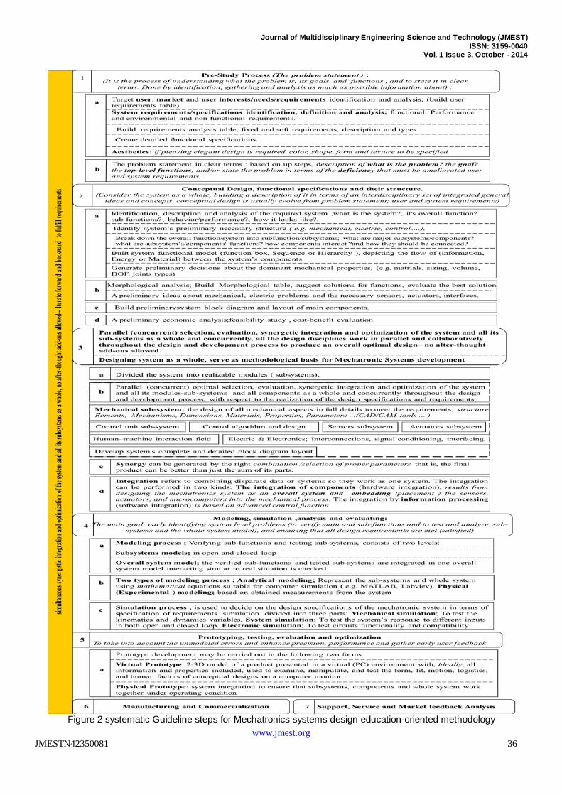
Figure 2 systematic Guideline steps for Mechatronics systems design education-oriented methodology
www.jmest.org JMESTN42350081 36
Journal of Multidisciplinary Engineering Science and Technology (JMEST) ISSN: 3159-0040
Vol. 1 Issue 3, October - 2014
2. PROPOSED GUIDELINE FOR MECHATRONICS SYSTEMS DESIGN EDUCATION-ORIENTED METHODOLOGY
In the following, the proposed simple, clear, easy to memorize and follow design steps, shown in diagram Figure 2, in solving Mechatronics design tasks are to be explained and discussed. 2.1 The Pre-Study Process- problem statement; it is the process of gathering as much information as possible about the product and its future applications, all possible conditions of operation, the environmental factors, and the specifications with respect to quality, physical dimensions, and costs. Identification, studying, definition and analysis of target market, target user (Customer), user’s needs/interests/requirements, system requirements, aesthetics, resulting in a preliminary design specification, which has to be updated continuously according to the new information gathered during the development process. 2.1.1 User and system requirements identification and analysis; The systems engineering standard (EIA 632) defines “requirement” as “something that governs what, how well, and under what conditions a product will achieve a given purpose”. Requirements can be; 1) Functional requirements (what the major functions that the system needs to perform?, Does the system do what it is supposed to do? ), 2) Performance requirements (How well does the system do its functions?). 3) Environmental non-functional requirements (Under what conditions (e.g. environmental, reliability, and availability) does the system have to work and meet its performance goals? ). The goal of requirements analysis is to determine the needs that make up a system to satisfy an overall need [21]. The success of the final product is highly dependent on the requirements identification process; It is of the highest importance to create a complete and accurate representation of all requirements [17]. 2.1.1.1 User requirements identification and analysis; Mechatronic system design life-cycle starts with the user requirements analysis stage in order to acquire the system’s specifications and requirements [18] .User's requirements analysis is to acquire necessary information to identify, understand and discover potential user, user's needs, interests, requirements and define system functions and sub-functions. 1) Proper understanding and clearly specified end-user needs/requirements is an integral part of design and is critical to the success of final product. 2) User requirements could include; selling price, performance, usability; user friendly product, easy and simple to use, safe, reliable, available, maintainable, energy consumption, aesthetics: outer design, color, shape, size, space, weight. 3) Users seldom know what they want or need, engineers must enter the customer's environment (e.g. Through Surveys, Interviews, Evaluation of an existing product) and find out the end-user needs/requirements, how the users will use the
system?, design must exceed, not merely meet, customer expectations, 4) Creativity of designers is required for the transfer of user requirements into innovative product. 2.1.1.2 System requirements identification and analysis; It start with a set of operational requirements and end with a complete set of production specifications, operation, maintenance, and training manuals and all other information needed to replicate, operate, maintain, and repair the system. The primary goal of system requirements analysis is to have well-defined product specifications and requirements, to create a detailed functional and performance specifications and defining the full set of system capabilities to be implemented. There are two types of system requirements; 1) Fixed or Mandatory system requirements; are the minimal requirements necessary to satisfy the customer's operational need. 2) Soft or Trade-off system requirements; after understanding the mandatory requirements, Engineers propose alternative candidate designs, all of which satisfy the mandatory requirements. Then the tradeoff requirements are evaluated to determine the preferred designs. 3) Treating user and system requirements as the same thing will create problems for projects. 2.1.2 Aesthetics In some instances this is not important, particularly where the device or structure is not seen. However, for many consumer products or structures a pleasing elegant outer design is required and color, shape, form and texture should be specified [14]. 2.1.3 The problem statement: it is a list and description of problem(s) that is given to a problem solving team as a sort of brief, before they attempt to solve the problem. The problem statement is more important than problem solving, where before attempting to find solution (design and built) for a given a problem, it is very important understanding what is problem and to state it in clear unambiguous manners and terms. The problem statement includes: up mentioned steps, in particular, verbal description of what is the problem to be solved, the goal to achieve, description of the top-level functions, system must perform and it might be better to state the problem in terms of the deficiency that must be ameliorated [15] the user needs and requirements, system requirements, aesthetics, also defines the business needs, prescribes the system capabilities and method used to solve the problem.
2.2 CONCEPTUAL DESIGN; CONCEPTUAL MODEL, FUNCTIONAL SPECIFICATIONS AND THEIR STRUCTURE. In Mechatronics design approach, it is important to consider the system as a whole throughout the development process from the very start of the design process. Conceptual design is an early stage of design in which designers are building a description of the proposed system in terms of an interdisciplinary set of integrated general ideas and concepts, describing product and product's overall function, its most important sub-functions, that will be employed in solving a given
www.jmest.org JMESTN42350081 37
Journal of Multidisciplinary Engineering Science and Technology (JMEST) ISSN: 3159-0040
Vol. 1 Issue 3, October - 2014
design problem and their supporting analysis, generating solutions without detailed design parameters and decide how to interconnect these concepts into an appropriate system architecture. Conceptual design acts as a blueprint for the subsequent design and implementation stages [18]. Conceptual design is usually evolve from user and system requirements, 1) Identification, verbal description and analysis of the required system; a) what is the system, b) what are overall system tasks, overall function and sub-functions, which are to be carried out by the system, c) desired behavior, d) how it looks like...2) Identify system’s preliminary necessary structure -subsystems (e.g. mechanical, electric, control), 3) Break down the overall function/system into sub-function/sub-systems or even components to which suitable operating principles or solution principles are assigned, a) what is system’s major subsystems/components?, b) what are subsystems’/components’ functions? c) how subsystems/components interact and d) how they should be connected? 4) Build system functional structure model (function box, Sequence or Hierarchy ) and depicting the flow of (information, Energy or Material) between the system’s required components, 5) Generate preliminary decisions about the dominant mechanical properties, (e.g. materials, sizing, volume, DOF, joints types) yielding a simple model that can be used for controller design, control software development and to initiate the CAD design, Choices and decisions can be made with respect to the mechanical properties needed to achieve a good performance of the controlled system. 6) Morphological analysis; Build Morphological table and corresponding analysis; a) suggest solutions for each function in functional structure model (creativity methods, Brainstorming), b) evaluate the best solution (e.g. Does the solution satisfy all the requirements?), c) A preliminary ideas about the necessary sensors, actuators, and interfaces.7) Build preliminary system block diagram of main components. 8) A preliminary study of feasibility (satisfying the needs/requirements is feasible), costs, and benefits. One of the most important secrets of the successful design is to keep design options open as long as possible, during conceptual design stage a new requirements may arise within the process which should be considered. The conceptual design is always refined, developed and optimized during various design phases. During the conceptual design phase few people are involved (e.g. mechanical designers, the technical personnel) in the development project.
.3.3 PARALLEL (CONCURRENT) SELECTION, EVALUATION, INTEGRATION AND OPTIMIZATION OF THE SYSTEM AND ALL ITS SUB-SYSTEMS AND COMPONENTS AS A WHOLE AND CONCURRENTLY, ALL THE DESIGN DISCIPLINES WORK IN PARALLEL AND COLLABORATIVELY THROUGHOUT THE DESIGN AND DEVELOPMENT PROCESS TO PRODUCE AN OVERALL OPTIMAL DESIGN– NO AFTER-THOUGHT ADD-ONS ALLOWED.
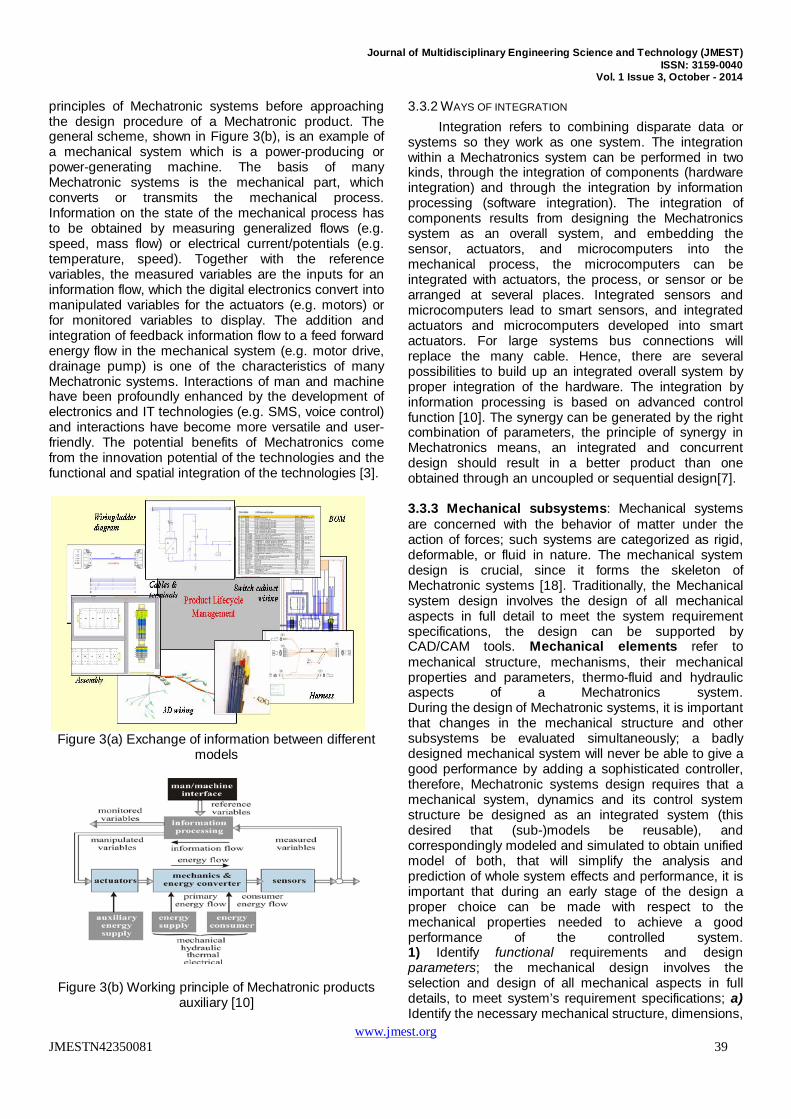
Mechatronics engineer is expected to design products with synergy and integration toward constrains like higher performance, speed, precision, efficiency, lower costs and functionality, also Mechatronics engineer must be skilled in modeling, simulation, analysis, and control of dynamic systems and understand the key issues in hardware implementation. The design of Mechatronic systems can be facilitated using a methodology called systems engineering. Systems engineering is an interdisciplinary collaborative robust approach that integrates disciplines and technologies to the design, creation, and operation of systems to ensure that the customer's needs are satisfied throughout a system's entire life cycle. Systems Engineering mainly, focuses on; a) The "whole system" and the "system life-cycle" and a bias towards the design of complex systems, b) The integration of all of different multidisciplinary aspects (modeling, simulating, analysis, refining, prototyping, validation, and deployment cycle ) into a coherent and effective system. Mechatronics systems design is modern interdisciplinary design procedure; it is a concurrent selection, evaluation, integration, and optimization of the system and all its subsystems and components as a whole and concurrently all the design disciplines work in parallel and collaboratively throughout the design and development process to produce an overall optimal design– no after-thought add-ons allowed, here it is important to notice that the ideal process of concurrent (simultaneous) approach is characterized by parallel work of a potentially distributed community of designers that know about the parallel work of their colleagues and collaborate as necessary; sharing of knowledge in a common database builds a basis of cooperative design, since a shared database is the place where all design results are integrated [20]. Since Mechatronic system consists of many different interconnected subsystems (components and elements), and once the system is specified after a problem statement, conceptual design and determination of all necessary requirements, the system can be divided into realizable modules (subsystems), the optimal selection, evaluation, integration, optimization, the exchange of information between different modules (example is shown in Figure 3(a) and models of different domains (e.g. MCAD, ECAD)), synergetic integration of modules and all components, to be designed in parallel and collaboratively with respect to the realization of the design specifications and requirements in the different domains, to produce an overall optimal design. Considering different interconnected subsystems of Mechatronic system, there will be energy conversion from one form to another, particularly between electrical energy and mechanical energy, this enables one to use energy as the unifying concept in the analysis and design of a Mechatronic system [7].
3.3.1 MECHATRONIC – BASIC APPROACH
Regardless of the type of Mechatronic system, there is a need to understand the fundamental working
www.jmest.org JMESTN42350081 38
Journal of Multidisciplinary Engineering Science and Technology (JMEST) ISSN: 3159-0040
Vol. 1 Issue 3, October - 2014
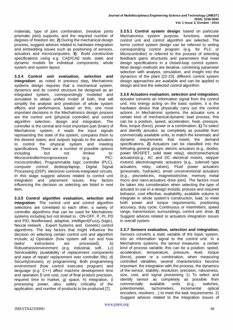
principles of Mechatronic systems before approaching the design procedure of a Mechatronic product. The general scheme, shown in Figure 3(b), is an example of a mechanical system which is a power-producing or power-generating machine. The basis of many Mechatronic systems is the mechanical part, which converts or transmits the mechanical process. Information on the state of the mechanical process has to be obtained by measuring generalized flows (e.g. speed, mass flow) or electrical current/potentials (e.g. temperature, speed). Together with the reference variables, the measured variables are the inputs for an information flow, which the digital electronics convert into manipulated variables for the actuators (e.g. motors) or for monitored variables to display. The addition and integration of feedback information flow to a feed forward energy flow in the mechanical system (e.g. motor drive, drainage pump) is one of the characteristics of many Mechatronic systems. Interactions of man and machine have been profoundly enhanced by the development of electronics and IT technologies (e.g. SMS, voice control) and interactions have become more versatile and user-friendly. The potential benefits of Mechatronics come from the innovation potential of the technologies and the functional and spatial integration of the technologies [3].
Figure 3(a) Exchange of information between different
models
Figure 3(b) Working principle of Mechatronic products auxiliary [10]
3.3.2 WAYS OF INTEGRATION
Integration refers to combining disparate data or systems so they work as one system. The integration within a Mechatronics system can be performed in two kinds, through the integration of components (hardware integration) and through the integration by information processing (software integration). The integration of components results from designing the Mechatronics system as an overall system, and embedding the sensor, actuators, and microcomputers into the mechanical process, the microcomputers can be integrated with actuators, the process, or sensor or be arranged at several places. Integrated sensors and microcomputers lead to smart sensors, and integrated actuators and microcomputers developed into smart actuators. For large systems bus connections will replace the many cable. Hence, there are several possibilities to build up an integrated overall system by proper integration of the hardware. The integration by information processing is based on advanced control function [10]. The synergy can be generated by the right combination of parameters, the principle of synergy in Mechatronics means, an integrated and concurrent design should result in a better product than one obtained through an uncoupled or sequential design[7]. 3.3.3 Mechanical subsystems: Mechanical systems are concerned with the behavior of matter under the action of forces; such systems are categorized as rigid, deformable, or fluid in nature. The mechanical system design is crucial, since it forms the skeleton of Mechatronic systems [18]. Traditionally, the Mechanical system design involves the design of all mechanical aspects in full detail to meet the system requirement specifications, the design can be supported by CAD/CAM tools. Mechanical elements refer to mechanical structure, mechanisms, their mechanical properties and parameters, thermo-fluid and hydraulic aspects of a Mechatronics system. During the design of Mechatronic systems, it is important that changes in the mechanical structure and other subsystems be evaluated simultaneously; a badly designed mechanical system will never be able to give a good performance by adding a sophisticated controller, therefore, Mechatronic systems design requires that a mechanical system, dynamics and its control system structure be designed as an integrated system (this desired that (sub-)models be reusable), and correspondingly modeled and simulated to obtain unified model of both, that will simplify the analysis and prediction of whole system effects and performance, it is important that during an early stage of the design a proper choice can be made with respect to the mechanical properties needed to achieve a good performance of the controlled system. 1) Identify functional requirements and design parameters; the mechanical design involves the selection and design of all mechanical aspects in full details, to meet system’s requirement specifications; a) Identify the necessary mechanical structure, dimensions,
www.jmest.org JMESTN42350081 39
Journal of Multidisciplinary Engineering Science and Technology (JMEST) ISSN: 3159-0040
Vol. 1 Issue 3, October - 2014
materials, type of joint combination, (revolute joints prismatic joint) supports, and the required number of degrees of freedom etc. 2) During the mechanical design process, suggest advices related to hardware integration and embedding issues such as positioning of sensors, actuators and microcomputers. 3) Build constructive specifications using e.g. CAD/CAE tools, static and dynamic models for individual components, whole system and system layout. 3.3.4 Control unit evaluation, selection and integration: as noted in previous step, Mechatronic systems design requires that a mechanical system, dynamics and its control structure be designed as an integrated system, correspondingly modeled and simulated to obtain unified model of both, that will simplify the analysis and prediction of whole system effects and performance, based on this, one most important decisions in the Mechatronics design process are the control unit (physical controller) and control algorithm selection, design and integration. The controller is the central and most important part (brain) of Mechatronic system, it reads the input signals representing the state of the system, compares them to the desired states, and outputs signals to the actuators to control the physical system and meeting specifications. There are a number of possible options including but not limited to: Microcontroller/microprocessor (e.g. PIC-microcontroller), Programmable logic controller (PLC), computer control; desktop/laptop, Digital Signal Processing (DSP), electronic-controls-integrated circuits. In this stage suggest advices related to control unit integration and placement issues. Key factors influencing the decision on selecting are listed in next item. 3.3.5 Control algorithm evaluation, selection and integration: The control unit and control algorithm selections are correlated to each other, a variety of controller algorithms that can be used for Mechatronic systems including but not limited to : ON-OFF, P, PI, PD and PID, feedforward, adaptive, intelligent(Fuzzy (logic), Neural network , Expert Systems and Genetic) control algorithms. The key factors that might influence the decision on selecting certain control unit and algorithm include; a) Operation (how system will run and how tasks/ instructions are processed), b) Robustness/environment (e.g. industrial, soft.. ),c) Serviceability (availability of replacement components and ease of repair/ replacement over controller life), d) Security(viruses), e) programming: Both programming environment (how control executes program) and language (e.g. C++) affect machine development time and operation f) unit cost, cost of final product precision, required time to market, g) space, h) integration, i) processing power, also, safety criticality of the application, and number of products to be produced [7].
3.3.5.1 Control system design: based on particular Mechatronics system purpose, functions, selected control unit and control algorithm are selected. The terms control system design can be referred to writing corresponding control program (e.g. for PLC or Microcontroller) or referred to the process of selecting feedback gains structures and parameters that meet design specifications in a closed-loop control system. Most design methods are iterative, combining parameter selection with analysis, simulation, and insight into the dynamics of the plant [22-23], different control system design approaches are available and can be applied to design and test the selected control algorithm. 3.3.6 Actuators evaluation, selection and integration; actuator converts an information signal from the control unit, into energy acting on the basic system, it is the hardware device that physically carry out the control actions .In Mechatronic systems, the actuator runs a certain kind of mechanical-dynamic load process, this can be a position, speed, acceleration, heat, pressure, flow, torque (force), power or a combination..1) To select and identify actuator, as completely as possible from commercially available units, to match the kinematic and dynamic requirements that meets the demand specifications. 2) Actuators can be classified into the following general groups: electric actuators (e.g., diodes, power MOSFET, solid state relay), electromechanical actuators(e.g., AC and DC electrical motors, stepper motors) electromagnetic actuators (e.g., solenoid type actuators, relay, valves), Fluid power actuators (pneumatic, hydraulic), smart unconventional actuators (e.g., piezoelectric, magnetostrictive, memory metal micro and nano-actuators drive joint). The factors must be taken into consideration when selecting the type of actuator to use in a design include; process and required behavior, cost effective, availability, available volume to integrate in whole system’s construction, load, to meet both power and torque requirements, positioning accuracy, duty cycle; Continuous or intermittent, speed range, transmission, surroundings, control unit, drive, 3) Suggest advices related to actuators integration issues in overall system. 3.3.7 Sensors evaluation, selection and integration; Sensors converts a state variable of the basic system, into an information signal to the control unit. In a Mechatronic systems, the sensor measures a certain kind of process variable, this can be a position, speed, acceleration, temperature, pressure, level, torque (force), power or a combination, when measuring controlled variables, several characteristics become important: the integration with the process, the dynamics of the sensor, stability, resolution, precision, robustness, size, cost, and signal processing 1) To select and identify sensor as completely as possible from commercially available units (e.g., switches, potentiometer, tachometers, incremental optical encoders, resolvers…) to meet the task requirements. 2) Suggest advices related to the integration issues of
www.jmest.org JMESTN42350081 40
Journal of Multidisciplinary Engineering Science and Technology (JMEST) ISSN: 3159-0040
Vol. 1 Issue 3, October - 2014
sensors and the signal processing on common carrier, or one chip, and on overall system. 3.3.8 Interconnection, signal conditioning, and interfacing; selection, design and integration; Selecting sensors and actuators is followed by evaluating, selecting and integrating of power supplies, drives circuits, signal processing-conditioning circuits, and data acquisition systems in order to interface the system components in and to optimize the system performance. In this stage, corresponding circuits-components e.g. amplifiers, analog signal conditioning circuits, converters DAC, ADC, power transistors and others are selected in order to match the sensor, controller and actuators specifications and ratings. The drive is the link between the controller and actuator, the drive main job is to translate the low energy reference signals from the controller, (e.g. Microcontroller, PC, PIC), into high energy power signals to the actuator (e.g. motor). In this stage, suggest advices related to the integration issues of sensors/actuators and the signal processing on common carrier, or one chip, on overall system design. The real-time interface process falls into the electrical and information system categories. In Mechatronics, the main purpose of the real-time interface system is to provide data acquisition and control functions for microcomputer. The purpose of the acquisition function is to reconstruct a sensor waveform as a digital sequence and make it available to the computer software for processing. 3.3.9 Selection and integration of human–machine interaction field: Control of the machine, and feedback from the machine which aids the user (e.g operator, user) in making operational decisions, including but not limited to : efficient, simple and easy to understand and use interface, enjoyable to operate a machine, simple input/ output means such as LEDs, digital display, LCD, touch screens, voice activation. 3.3.11 Develop complete and detailed system block diagram layout: Based on overall system, sub-systems and components selection, design and integration, a complete and detailed system block diagram layout is developed, showing interconnections and interrelation and energy flow.
3.4 MODELING, SIMULATION, ANALYSIS AND EVALUATION
Modeling, simulation and evaluation, play a critical role during the design stages of a Mechatronic system, the primary challenge in modeling Mechatronic systems lies in their multi-domain nature, consisting of many different interconnected, interdisciplinary, integrated subsystems (and components such as sensors, actuators, interfaces and mechanical geometry), therefore, modeling in Mechatronic is multidisciplinary and crosses domain boundaries. Based on this , is assumed that the key essential characteristics of a Mechatronics engineer and success in Mechatronics design, are a balance between
two skills; Modeling/Analysis skills and Experimentation/Hardware implementation skills [5][1]. In evaluating concepts, a modeling-simulation-and-analysis approach must replace any design-build-and-test approach. Mechatronic system has multi-domain nature, consisting of many different interconnected, interdisciplinary, integrated subsystems (components and elements), the primary challenge in modeling Mechatronic systems lies in their multi-domain nature , where modeling is multidisciplinary and crosses domain boundaries. mechatronics design approach challenge conventional sequential design approach, by connecting machine design and test tools and creating a virtual machine prototype before designing the physical machine, to take all advantages that can result from an integrated design, this approach offers less constrains and shortened development, also allows the design engineers to provide feedback to each other about how their part of design is effect by others[9][1].The main goal of Modeling, simulation, analysis and evaluation in Mechatronics design are ; early identifying system level problems (to verify sub-functions and test sub-systems), and ensuring that all design requirements are met.
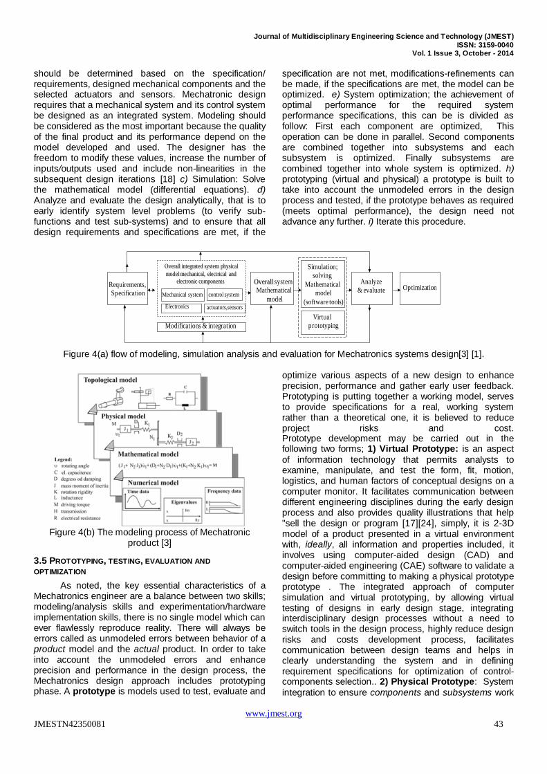
3.4.1 INTRODUCTIONS TO CONCEPTS AND CORRESPONDING DEFINITIONS Four types of models are usually given for Mechatronic systems; namely topologic, physic, mathematic and numeric [5]. A short introduction to these models and corresponding concepts in Mechatronics system design are followed: A model is a simplified representation of a system at some particular point in time or space intended to promote understanding of the real system. Modeling is the construction process of physical, conceptual or mathematical simulations of the real world. Mathematical Modeling: A process of representing the behavior of a real system by a collection of mathematical equations and/or logic. Topological modeling (see figure 4(b)): a mathematical approach that allows to structure data based on the principles of feature adjacency and feature connectivity (describes and reflects interlinks, the function-performing elements, basically the relative position between each component, without considering the physics behind), Topology of mechanical elements could be presented in various ways (e.g. graphs, free-body diagrams, tree-structure) and essentially determines the kinematics of Mechatronic systems, Based on topology descriptions, a physical model is created and describes system properties in system adapted variables – e.g. masses and length for mechanical systems [3-4]. Physical model; One that physically represents an object (see figure 4(b)),may be applied to understand the type of forces being acting and applied. Simulation is the process of solving the model i.e. solving mathematical equations and/or logic equations; simulation generally refers to a computerized version of the model which is run over time to study the implications of the defined interactions. In order to simulate a Mechatronic system, a multi-domain simulation environment is required. Multi-
www.jmest.org JMESTN42350081 41
Journal of Multidisciplinary Engineering Science and Technology (JMEST) ISSN: 3159-0040
Vol. 1 Issue 3, October - 2014
domain simulation could be achieved in different ways: a more traditional way is to use a general-purpose solver to simulate each subsystem and the whole integrated system, other way, called co-simulation. Co-simulation is to use different communicating solvers, to simulate each sub-system and whole system. It is a test software tool, used in order to validate the design choices and to develop the model on gradually decreasing levels of abstraction. Hardware-in-the-Loop simulation (HILS) is a technique that is used in the development and test of complex process systems and real-time embedded systems. It differs from pure real-time simulation by the addition of a real component in the loop via their electrical interfaces to a simulator, which reproduces the behavior of the real time environment; this component may be an electronic control unit or a real engine. Various kinds of HILS can be realized, simulation of electronics, mechanics, sensors and actuators. Optimization is to obtain maximum benefits, from the given resources under the given constraints, the achievement of optimal performance for the required system performance specifications. Unmodeled errors, Unfortunately it is usually very difficult to build exact mathematical model for complex mechatronics systems including all components. However, there is no single model which can ever flawlessly reproduce reality, there will always be errors called as unmodeled errors between behavior of a product model and the actual product. These unmodeled errors are the reason why there are so many model-based designs failed when deployed to the product. In order to take into account the unmodeled errors in the design process, the Mechatronics design approach includes virtual and physical prototyping phase. Prototyping is putting together a working model, serves to provide specifications for a real, working system rather than a theoretical one, it is believed to reduce project risks and cost. The modeling, simulation, analysis and evaluation processes in Mechatronics design consists of two levels; subsystems models (e.g. plant-dynamics, inertias, energy flow, gears, interfaces, sensors, actuators, control) and overall system model with various sub-system models interacting similar to real situation, all engineering subsystems (e.g. mechanical, electrical and electronic components) should be included in overall system model. There are two types of modeling process,. A) Analytical modeling: (models can be obtained by either a theoretical approach based on physical laws), It is the process of representing the system using mathematical equations (suitable for computer simulation) and used to describe changes in a system, analytical models are used to assist calculations and predictions (systems analyzing). Analytical component modeling plays a critical role during the design stages of a Mechatronic system. For all but the simplest systems, the performance aspects of components (such as sensors, actuators, and mechanical geometry) and their effect on system performance can only be evaluated by simulation [6]), b) Physical (Experimental) modeling:
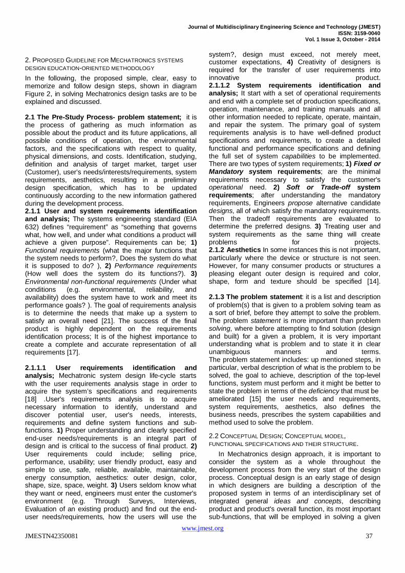
models can be obtained experimental approach based on obtained measurements from the system. Once models are available, simulation is used to decide on the design specifications of the Mechatronic system based on the specification of requirements. The simulation can be divided into three parts: mechanical, electronic and system; Mechanical simulation; used to test the kinematics and dynamics variables. System simulation; to test the system’s response to different inputs in both open and closed loop, where control system (laws) design involves formulation of reasonably accurate models of the plant to be controlled, designing control laws based on the derived models and simulating the designed control laws using available simulation tools e.g ProEngineer and Solid-Works, MATLAB/Simulink, Labview. The subsystem model parameters should be determined based on the designed mechanical components and the selected actuators and sensors. The designer has the freedom to modify these values, increase the number of inputs/outputs used and include non-linearities in the subsequent design iterations [19]. Electronic simulation; To test circuits functionality and compatibility and evaluate the selection and design of interconnections, signal conditioning, and interfacing circuits, including; Drive-circuits ( e.g. relays, MOSFETs, L93DIC, transistors,), signals ( e.g. control signal, PWM signal), programming of control unit (e.g. Microcontroller), sensors, motor position-speed, the overall system or any such subsystem can be simulated using different computer software tools e.g. Saber, ISIS-Proteus and MATLAB. Commercial software tools available to design, model and simulate Mechatronic systems, that allow the study and analysis of components interaction and variation in design include MATLAB/Simulink, labview, Scilab/Scicos, Ptolemy, JMathLib [20],CAE tools, 3D-CAD softwares Pro/Engineer, CATIA, AMESim, ASCET-SD/CT, Saberand SolidWorks for visualization and collision detection ,MATRIX-X, ACSL. A flow of modeling, simulation analysis and evaluation for Mechatronics systems design and integration procedure could be as follows (diagram 4(a)[3]): a) Problem statement: establish the goals to achieve; based on the specification of requirements and design (as well as, constrains, assumptions, performance predictions). b) System representation: 1) Since Mechatronic system consists of many different interconnected subsystems (components and elements), divided the system into realizable modules (sub-systems/sub-functions), and develop physical model; represent the integrated physical system using physical model. 2) Develop the functional block diagram and show interconnections of sub-systems and components, 3) Develop mathematical model: represent system by correct dynamic equations (differential equations), this is done by first by modeling the component, then the subsystem, and finally integrated all subsystems to develop whole system model. In this stage, the component, plant and subsystems models parameters
www.jmest.org JMESTN42350081 42
Journal of Multidisciplinary Engineering Science and Technology (JMEST) ISSN: 3159-0040
Vol. 1 Issue 3, October - 2014
should be determined based on the specification/ requirements, designed mechanical components and the selected actuators and sensors. Mechatronic design requires that a mechanical system and its control system be designed as an integrated system. Modeling should be considered as the most important because the quality of the final product and its performance depend on the model developed and used. The designer has the freedom to modify these values, increase the number of inputs/outputs used and include non-linearities in the subsequent design iterations [18] c) Simulation: Solve the mathematical model (differential equations). d) Analyze and evaluate the design analytically, that is to early identify system level problems (to verify sub-functions and test sub-systems) and to ensure that all design requirements and specifications are met, if the
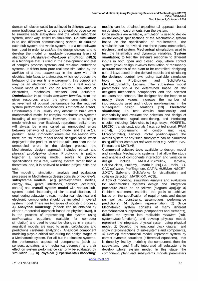
specification are not met, modifications-refinements can be made, if the specifications are met, the model can be optimized. e) System optimization; the achievement of optimal performance for the required system performance specifications, this can be is divided as follow: First each component are optimized, This operation can be done in parallel. Second components are combined together into subsystems and each subsystem is optimized. Finally subsystems are combined together into whole system is optimized. h) prototyping (virtual and physical) a prototype is built to take into account the unmodeled errors in the design process and tested, if the prototype behaves as required (meets optimal performance), the design need not advance any further. i) Iterate this procedure.
Figure 4(a) flow of modeling, simulation analysis and evaluation for Mechatronics systems design[3] [1].
Figure 4(b) The modeling process of Mechatronic
product [3]
3.5 PROTOTYPING, TESTING, EVALUATION AND OPTIMIZATION
As noted, the key essential characteristics of a Mechatronics engineer are a balance between two skills; modeling/analysis skills and experimentation/hardware implementation skills, there is no single model which can ever flawlessly reproduce reality. There will always be errors called as unmodeled errors between behavior of a product model and the actual product. In order to take into account the unmodeled errors and enhance precision and performance in the design process, the Mechatronics design approach includes prototyping phase. A prototype is models used to test, evaluate and
optimize various aspects of a new design to enhance precision, performance and gather early user feedback. Prototyping is putting together a working model, serves to provide specifications for a real, working system rather than a theoretical one, it is believed to reduce project risks and cost. Prototype development may be carried out in the following two forms; 1) Virtual Prototype: is an aspect of information technology that permits analysts to examine, manipulate, and test the form, fit, motion, logistics, and human factors of conceptual designs on a computer monitor. It facilitates communication between different engineering disciplines during the early design process and also provides quality illustrations that help "sell the design or program [17][24], simply, it is 2-3D model of a product presented in a virtual environment with, ideally, all information and properties included, it involves using computer-aided design (CAD) and computer-aided engineering (CAE) software to validate a design before committing to making a physical prototype prototype . The integrated approach of computer simulation and virtual prototyping, by allowing virtual testing of designs in early design stage, integrating interdisciplinary design processes without a need to switch tools in the design process, highly reduce design risks and costs development process, facilitates communication between design teams and helps in clearly understanding the system and in defining requirement specifications for optimization of control-components selection.. 2) Physical Prototype: System integration to ensure components and subsystems work
Requirements, Specification
Overall integrated system physical model mechanical, electrical and
electronic components Overall system Mathematical
model
Simulation; solving
Mathematicalmodel
(software tools)
Analyze & evaluate Optimization
Modifications & integration
Mechanical system
actuators,sensorsElectronics
control system
Virtual prototyping
www.jmest.org JMESTN42350081 43
Journal of Multidisciplinary Engineering Science and Technology (JMEST) ISSN: 3159-0040
Vol. 1 Issue 3, October - 2014
together. Testing and evaluation should be done under normal operating conditions and desired performance specifications and preferably at an actual application environment. The shortcomings of designed system should be identified; correspondingly design of Mechatronics system should be refined, and possibly redesigned, to overcome any shortcomings. The integrated approach of computer simulation and virtual prototyping, by allowing virtual testing of designs in early design stage, integrating interdisciplinary design processes without a need to switch tools in the design process, highly reduce design risks and costs development process, facilitates communication between design teams and helps in clearly understanding the system and in defining requirement specifications for optimization of control-components selection.
3.6 MANUFACTURING AND COMMERCIALIZATION
Once the developed system is tested, refined, and confirmed to satisfy the required specifications, the processes of technology transfer to industry and commercialization, could begin. Prepare products documents including preparing necessary production and operation structures, infrastructure and an approved business plan, and funds. Suitable plans for commercial development and marketing. According to the existing practice, engineers, scientists, and technicians provide minimal input into these activities which is not desirable and needs to be greatly improved [17][24].
3.7 SUPPORT, SERVICE AND MARKET FEEDBACK ANALYSIS. The sustained success of products commercial and marketing depends on market feedback analysis and a comprehensive range of customer support and service including a highly experienced team of support and service engineers that enables manufactures to provide a broad spectrum of services including; Consulting Services, Operational Services, Application Services. Market feedback analysis is to use of objective market data, customer satisfaction surveys, interviews, routine interactions and communications, product and service quality and reliability data, to give insight into customers' perspective and expectations of product modifications of design and performance.
4. CONCLUSIONS
The key element in success of a Mechatronics engineering education-program, and correspondingly, Mechatronics engineering graduates, is directly related to the applied structural design methodology. Based on VDI 2206 guideline and different industrial, scientific and educational resources, a Mechatronics systems design education-oriented methodology is proposed to fulfill Mechatronics optimal program requirements. The proposed methodology consists of a systematic specific simple and clear steps (shown in diagram 1) that are easy to memorize, follow and support non experienced student or group of students in solving Mechatronics
design integrated tasks. The design methodology aims to integrate multidisciplinary knowledge, in various stages including pre-study process-problem statement, conceptual design, Parallel (concurrent) selection, evaluation, integration and optimization of the system and all its sub-systems and components as a whole and concurrently modeling, simulation, prototyping, analysis and physical implementations through the design process and development of Mechatronics product. the design and implementation of functional prototypes are an essential learning experience for the students, as future work, the proposed methodology or selected steps, to be applied, discussed and evaluated to propose Mechatronics design and implementation of different systems or modules .
REFERENCES
[1] K. Craig, F. Stolfi “Teaching control system design through mechatronics: academic and industrial perspectives.” Mechatronics, Vol 12, No. 2, pp. 371-381, 2002,
[2] Farhan A. Salem Ahmad A. Mahfouz’’ A Proposed Approach to Mechatronics Design and Implementation Education-Oriented Methodology’’Innovative Systems Design and Engineering, Vol.4, No.10, pp 12-29, 2013.
[3] Vasilije S. Vasić (2008), Mihailo P. Lazarević, Standard Industrial Guideline for Mechatronic Product Design , FME Transactions, 104 , vol. 36, No 3, .
[4] Lyshevski, S.E.(2002): Mechatronic curriculum – retrospect and prospect, Mechatronics, Vol. 12, No. 2, pp. 195-205.
[5] VDI, Verein Deutscher (2004), Ingenieure (Ed.), VDI guideline 2206,2004-06, title '' Design methodology for mechatronic systems'' VDI-Society Product and Process Engineering, Author: Technical Division Product Development and Mechatronics,
[6] Devdas Shetty, Richard A. Kolk, Mechatronics systems design, II edition, (Ch 2, pp41-123, MODELING AND SIMULATION OF PHYSICAL SYSTEMS) , Cengage Learning, Stamford, USA, 2011.
[7] De Silva, Clarence W. (2008), Mechatronics: An Integrated Approach, CRC Press, 2005.
[8] Robert Bishop, Francis C. Moon, mechatronics systems, sensors and actuators, fundamentals and modeling,( Francis C. Moon, Section II, Physical System Modeling), CRC Press, Tyler and francis group, Newyork, 2008.
[9] Sarah Brady (2008), Multidisciplinary machine building, the institute of engineering technology http://eandt.theiet.org/magazine/2008/12/machine-building.cfm
[10] Rolf Isermann (1996), Modeling and Design Methodology for mechatronics Systems,IEE/SME transaction on mechatronics, VOL. 1, No 1.
[11] Manfred Lohöfene (2008), design of mechatronics systems and benefits of open source software tools, 9th International Workshop on Research and Education in Mechatronics September 18th-19th , Bergamo, Italy
[12] P. Hehenberger, K. Zeman(2004), Hierarchical structuring of mechatronics design models, Elesevier, 3rd IFAC symposium, volume 2,
[13] J. Burr (1989), Mechatronics design in Japan: a study of Japanese design methods and working practice in Japanese companies. Lyngby: Technical University of Denmark, .
[14] Ken Hurst (2004), Engineering design principles, Elisevier , [15] Andrew P. Sage (2009), William B. Rouse, system engineering
and management, Wiley and sons, 2nd edition, . [16] Isermann, R.(2002): Mechatronic design approach, in Bishop,
R.H. (Ed.): The Mechatronics Handbook, CRC Press, Boca Raton, Section I: Overview of mechatronics, ch. 2, p. 3, .
[17] Rexroth, Bosch Group, Drive and control profile : PC vs. PLC key features in comparing control options, www.boschrexroth-us.com , 2011, also, L Al-Sharif (2010), A Saleem, and TA Tutunji,
www.jmest.org JMESTN42350081 44
Journal of Multidisciplinary Engineering Science and Technology (JMEST) ISSN: 3159-0040
Vol. 1 Issue 3, October - 2014
Mechatronic system design: The ideal capstone course? 7th International Symposium on Mechatronics and its Applications (ISMA), also L Al-Sharif "Mechatronics System Design 0908531: Course Notes", Mechatronics Engineering Department, University of Jordan. And
[18] A. Saleema (2011), T. Tutunji and L. Al-Sharif, Mechatronic system design course for undergraduate programmes,European Journal of Engineering Education,Vol. 36, No. 4, August 2011, 341–356.
[19] Manfred Lohöfener (2008), design of mechatronics system and benefits of open source software tools, 9th International Workshop on Research and Education in Mechatronics September 18th-19th , Bergamo, Italy.
[20] John Billingsley (2008), ''Essentials of Mechatronics'' , John Wiley & Sons,2006. Kenway Chen, Jitesh Panchal, Dirk Schaefer , an integrated approach to design mechatronics systems: cross-disciplinary constraint modeling'' , ASME International Design Engineering Technical Conferences & Computers and Information in Engineering Conference, IDETC/CIE 2008, New York City .
[21] Space & Missile Systems Center U.S. Air Force(2004) ,SMC Systems Engineering Primer & Handbook , , 2-edition.– Page 58 - 59,2004.
[22] D'AzzoJohn Joachim, Houpis, Constantine H, “Linear control system analysis and design: conventional and modern“, 1988) .
[23] Hedaya Alasooly, ''Control of DC motor using different control strategies'' global journal of technology and optimization, 2011.
[24] James C. Schaaf Jr. and Faye Lynn Thompson. “Systems Concept Development with Virtual Prototyping”. Proceedings of the 29th conference on Winter simulation, pp. 941 - 947. . DOI 10.1.1.74.2308, 1997.
.
www.jmest.org JMESTN42350081 45