a preliminary study of the effect of the free surface …
TRANSCRIPT

Department of the Navy
Naval Ordnance Test Station
Contract N123( 60530) 34767 A
A PRELIMINARY STUDY OF THE EFFECT
OF THE FREE SURFACE
ON A THREE- DIMENSIONAL CAVITY
PRODUCED BY A CIRCULAR DISK
E. R. Bate, Jr.
Hydrodynamics Laboratory
Karman Laboratory of Fluid Mechanics and Jet Propulsion
California Institute of Technology
Pasadena, California
Report No. E-118.15 March 1964

Department of the Navy Naval Ordnance Test Station Contract Nl23 (60530)34 767 A
A PRELIMINARY STUDY OF THE EFFECT OF THE
FREE SURFACE ON A THREE-DIMENSIONAL CAVITY
PRODUCED BY A CIRCULAR DISK
E. R. Bate, Jr.
Reproduction in whole or in part is permitted for any purpose of the United States Government
Hydrodynamics Laboratory Karman Laboratory of Fluid Mechanics and Jet Propulsion
California Institute of Technology
Report No. E-118. 15
Pasadena, California
Approved by: A. J. Acosta
March, 1964

Symbols
d
h
p - PK K = 0
1/2 p uz 1,
PK
p 0
u
p
NOMENCLATURE
Definition
Disk diameter
Submergence of disk center below the free surface
Ventilation number
Cavity length
Cavity pressure
Free stream pressure
Free stream velocity
Density of water
Units
Inches
Inches
Dimensionless
Inches
2 Pounds/feet
2 Pounds /feet
Feet/ second
2 Pound Second
Feet 4

Introduction
The influence of the free surface on the cavitation associated with
bodies operating at shallow submergences has long been of interest
because of the practical use for such information. The performance of
hydrofoil boats is very much dependent on the submergence below the
water surface of the hydrofoils, for example.
Because of the extreme complexity introduced by the consideration
of boundaries of any sort, most theories relating the parameters
associated with cavitation are developed for a fluid of "infinite" extent.
The task of determining the effects of the boundaries for such a cavitating
flow problem then becomes one of experimentation. Such an experiment
was performed to determine the free surface effects on a supercavitating,
flat plate hydrofoil in two-dimensional flow p:: However, most real flow situations are three dimensional, and the
present experiment is a preliminary study to determine the effects of
the free surface on the geometry of a ventilated cavity in such a flow.
Specifically, the variation of the length of a cavity due to submergence
is studied. The cavity is produced by a sharp- edged, circular disk
normal to the flow. Figures la and lb show this cavity at two different
ventilation numbers.
This experiment was planned as a preliminary study to determine
the general trend and order of magnitude of the free surface effects, For
this reason, the results are presented with the preliminary data reduced
to the pertinent dimensionless parameters, uncorrected for tunnel
blockage and model scale effects, if any.
Experimental Procedure and Equipment
The experiment was performed in the Hydrodynamics Laboratory
of the California Institute of Technology, in the Free-Surface Water
>:< Super scripts refer to references at the end of this text.
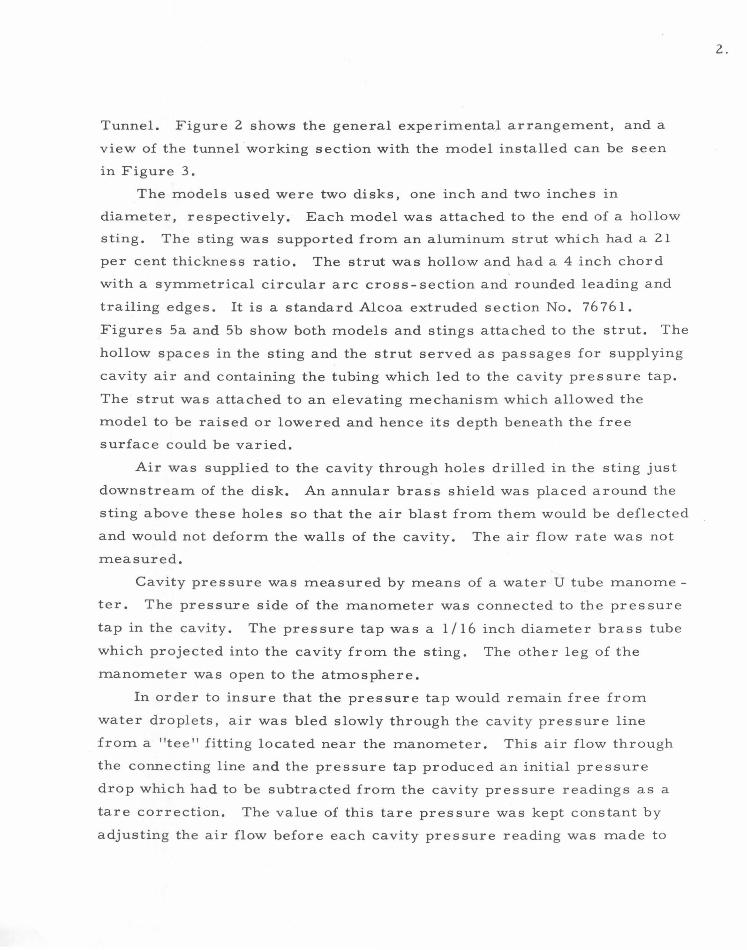
Tunnel. Figure 2 shows the general experimental arrangement, and a
view of the tunnel working section with the model installed can be seen
1n Figure 3.
The models used were two disks, one inch and two inches in
diameter, respectively. Each model was attached to the end of a hollow
sting. The sting was supported from an aluminum strut which had a 21
per cent thickness ratio. The strut was hollow and had a 4 inch chord
with a symmetrical circular arc cross- section and rounded leading and
trailing edges. It is a standard Alcoa extruded section No. 76761.
Figures Sa and 5b show both models and stings attached to the strut. The
hollow spaces in the sting and the strut served as passages for supplying
cavity air and containing the tubing which led to the cavity pres sure tap.
The strut was attached to an elevating mechanism which allowed the
model to be raised or lowered and hence its depth beneath the free
surface could be varied.
Air was supplied to the cavity through holes drilled in the sting just
downstream of the disk. An annular brass shield was placed around the
sting above these holes so that the air blast from them would be deflected
and would not deform the walls of the cavity. The air flow rate was not
measured.
Cavity pressure was measured by means of a water U tube manome
ter. The pressure side of the manometer was connected to the pressure
tap in the cavity. The pres sure tap was a 1 I 16 inch diameter brass tube
which projected into the cavity from the sting. The other leg of the
manometer was open to the atmosphere.
In order to insure that the pressure tap would remain free from
water droplets, air was bled slowly through the cavity pres sure line
from a "tee" fitting located near the manometer. This air flow through
the connecting line and the pressure tap produced an initial pressure
drop which had to be subtracted from the cavity pressure readings as a
tare correction. The value of this tare pressure was kept constant by
adjusting the air flow before each cavity pressure reading was made to
2.

the value which existed when the system was calibrated. A diagram
of the cavity pres sure measuring system can be seen in Figure 6.
Cavity lengths were determined by visually comparing the end
of the cavity with a scale that was held against the lucite window of
the tunnel working section. To eliminate parallax, a flashlight was
held directly beneath the observer's eye when a reading was made.
The observer moved axially along the tunnel until the reflection of this
light in the lucite window was aligned with the end of the cavity. The
cavity length was then determined by the location of the reflection of
the light with respect to the scale. Figure 4 shows a cavity length
measurement being made.
A problem encountered in making the cavity length measure
ment involved deciding what constituted the end of the cavity. All of
the cavities were viewed from the side and regardless of the type of
cavity closure (re-entrant jet or trailing vortices), they all had a
small area composed of a frothy mixture of air and water at their
immediate ends (see Figs. la and b). This frothy area was defined as
the cavity end, and all measurements were made to this point.
The flow in the vicinity of the end of the cavity was quite tur
bulent, producing a great deal of oscillation of the cav ity. This os
cillation also gave rise to difficulties in measuring the cavity lengths.
At best, the cavity length data can probably be considered accurate to
within ± 1 inch .
Discussion of Results
Figures 7 and 8 show the results in the form of cavity length
to-disk diameter ratios plotted against ventilation number for several
values of submergence-to-disk diameter ratios. At a given ventilation
number, the effect of the proximity of the free surface is to decrease
the cavity length.
Waid2
has also conducted an experimental program 1n the Free
Surface Water Tunnel in which the geometry of a cavity produced by a
circular disk was determined. From the data which was obtained, an
empirical equation was developed which relates the cavity half-length to
3.

the ventilation number (Reference (2), Equation 4). This equation
(multiplied by two to convert cavity half-length to total cavity length) has
been presented along with the data from the present experiment in Figures
7 and 8. Waid' s data was all taken at a constant submergence of 8 inches,
but the models used varied in diameter from 1 inch to 1/2 inch. Hence
the submergence ratios obtained in his experiment varied from 8. 0 to
16. o.
The data obtained in the present experiment shows longer cavity
lengths at equivalent ventilation numbers and submergence ratios than
the curve obtained by Waid. This is true for both of the disks tested
except for the 1 inch disk at a cavity length ratio below 15. Below this
value, the cavity was short enough that the pressure field associated
with the support strut was able to affect the flow near the end of the
cavity. This produced a shorter cavity than would have been obtained
if the strut were absent. During the testing, it was noticed that as the
air supply was increased to change the size of the cavity, the end of
the cavity tended to "stick" at the position of the strut until the air
supply had been increased sufficiently, at which time the cavity would
"spring" downstream.
A comparison between the data obtained with the 2 inch disk and the
1 inch disk in the present experiment shows that the cavity length ratios
are larger for the 2 inch disk at equivalent submergence ratios and
ventilation numbers. This result, as well as the disagreement between
this experiment and Waid' s can probably be explained by tunnel blockage.
The increased velocity in the vicinity of the cavity due to the flow block
age caused by the cavity itself would result in reduced ventilation
numbers. This would give rise to a cavity length which was longer than
one produced by a ventilation number based on the free stream velocity.
The Froude number range in the present experiment (Fr = 6 to 16)
was sufficiently close to the range of Waid' s experiment (Fr = 7 to 20),
that Froude number effects are probably not an important cause for the
disagreement between the two experiments.
4.

REFERENCES
1. Dawson, T.E. andBate, E.R.Jr., "AnExperimental Investigation of a Fully Cavitating Two- Dimensional Flat Plate Hydrofoil Near a Free Surface", California Institute of Technology, Hydrodynamics Laboratory, Report E-118. 12,
' October, 1962.
2. R. L. Waid, "Cavity Shapes for Circular Disks at Angles of Attack", California Institute of Technology, Hydrodynamics Laboratory, Report E-73. 4, September, 1957.
5.

6.
a. Re-entrant Jet Cavity Closure.
b. Trailing Vorticies.
Fig. l - Cavities Produced by 2 Inch Diameter Disk. Submergency = 12 Inches, Velocity= 14ft/ sec.

1.
Mo
del
an
d S
up
po
rt
Sti
ng
2.
Str
ut
3.
Ele
vati
ng
M
ech
an
ism
4.
Cav
ity
P
ressu
re
Man
om
ete
r
5.
Air
B
leed
R
ate
M
an
om
ete
r
6.
Tu
nn
el
To
tal
Head
M
an
om
ete
r
7.
Cav
ity
L
en
gth
S
cale
Fig
. 2
-V
iew
o
f E
xp
er
imen
tal
Fa
cil
itie
s.
-.J

..
•
-~ ":::'"-"'· < ~
~~~~-
Fig. 3 - 2 Inch Diameter Disk Mounte d 1n Water Tunnel Working Section.
Fig. 4- View of Test Facility Showing Experimental Cavity Length Measurement being made.
8 .

a.
2 In
ch
D
iam
ete
r D
isk
. b
. 1
Inch
D
iam
ete
r D
isk
.
Fig
. 5
-M
od
els
Sh
ow
n M
ou
nte
d t
o S
tru
t an
d S
tin
gs.
-.D

VA
LV
E
FO
R
VA
RIA
BL
E
PR
ES
SU
RE
O
RO
P
C O
NT
RO
C"\
3-W
AY
V
AL
VE
(F
OR
V
EN
TIN
G
MA
NO
ME
TE
R
TO
A
TM
OS
PH
ER
E)
~
PR
ES
SU
RE
R
EG
UL
AT
OR
rF
OR
F
LO
W
CO
NT
RO
L
-M
AIN
S
HU
T-O
FF
V
AL
VE
~===============~TO
RE
GU
LA
TE
D
AIR
S
UP
PL
Y
-+--
-CA
VIT
Y
AIR
S
UP
PL
Y
VA
LV
E
r__
CA
VIT
Y
CA
VIT
Y
AIR
~UPPLY
LIN
E
CA
VIT
Y
PR
ES
SU
RE
M
EA
SU
RIN
G
LIN
E
CIR
CU
LA
R
DIS
K
MO
DE
L
Fig
. 6
-D
iag
ram
o
f C
av
ity
P
ressu
re
Measu
rin
g
Sy
stem
.
......
0

30
2 5
2 0
~1-o
I a:: 1- w <.9 1-z w w :::!: 15 _j
<r
>- 0 1-- ~ > (f) <r -(.) 0
10
5
0 0
\ I
\
SYMBOL h;d ... 3
~ 4 .5
0 6
• 9
0 12
~ I
.05
\ \ ~ \ ~\ \ ..
·~~\ ... ~ID ~
~~\t
\\~ ~~~
~ ~
<2 h;d= 3 ~ -< ~
4 .5 ~ 6 4~ 9 (...
0 tv -.....!...'~ 12 ~o, J, IT
-.........:.. 2 I 'Cfe
WATER SURFACE
1 -
- h PK n _l U , P0
u L===J
I .10
VENTILATION NUMBER, K
..........................
. 15 . 20
Fig . 7 - Cavity Leng t h as a F unction o f V entilati on N u m b e r f or the 1 Inch Diameter Di sk .
11.

30 r--------------.r-\-------------.--------------~-------------.
\ \ \
25 ~-------------4---~\----------r--------------+--------------~
\ \
b \ ~ \ 2 0 1---------+-\--+-------+\ \. ~ ~
\ '0 \\\ ~I"C \\ \ :z: rr \ ·~ ~ \
0~ A\1\ ~~ z W I 5 1-------------------t------------<) I \ ".--\_),......+--- 4. 5
~ ~ h;d=l.5~r\\ 1'2\_ ~ ro ~ ~. 1- 3---- '\. ' 0~6 > ~ '\.
~~ ' 00 h ... SYMBOL /d " \
<> 1.5 ' ... 3 ~,~+ ~ ~Q, . ..,. 4 . 5 v4.,.
""-.: I 0
10
0 6 ~(<I) -..........: F?c,.
................ < ....._ WATER SURFACE
----------- f PK h
f}_l
~Ld:j 51--------
U, P0
0~------~'---------~~------~--------~ 0 .05 .10 .15 .20
VENTILATION NUMBER, K
Fig. 8 - Cavity Length as a Function of Ventilation Number for the 2 Inch Diameter Disk.
12.

DISTRIBUTION LIST
Chief, Bureau of Naval Weapons Department of the Navy Washington 25, D. C. Attn: Codes DLl-3 (1)
RAAD-3 ( 1) RRRE (1) RRRE-7 (l) RUAW-4 (2)
Chief, Bureau of Ships Department of the Navy Washington 25, D. C. Attn: Codes 335
421 442 644
Chief of Naval Research Department of the Navy Washington 25, D. C. Attn: Codes 429
438 466
(l) ( 2) ( 1) ( 1)
( 1) ( 1) ( 1)
Commanding Officer and Director David Taylor Model Basin Washington 7, D. C. Attn: Codes 142 (1)
500 (l) 526 (1) 591 ( 1)
Chief, Bureau of Yards and Docks Department of the Navy Washington 25, D. C. Attn: Research Division ( 1)
Commanding Officer and Director U.S. Naval Engrg. Experiment Sta. Annapolis, Maryland Attn: Librarian ( 1)
Superintendent U.S. Naval Academy Annapolis, Maryland Attn: Librarian ( 1)
Superintendent U.S. Naval Postgraduate School Monterey, California Attn: Librarian ( 1)
Commander U.S. Naval Weapons Laboratory Dahlgren, Virginia Attn: Librarian ( 1)
Commanding Officer U.S. Naval Underwater Ord. Sta. Newport, Rhode Island Attn: Librarian ( 1)
Commander U.S. Naval Ordnance Laboratory White Oak, Silver Spring, Md. Attn: Desk DL (Library) ( 1)
XL (Aeroballistics) (1)
Commanding Officer and Director U.S. Naval Civil Engrg. Laboratory Port Hueneme, California Attn: Librarian ( 1)
Commander U.S. Naval Ordnance Test Station Pasadena Annex 3202 E. Foothill Blvd. Pasadena, California Attn: Codes P508
Director
P804 P8074 P8076 P80962
Naval Research Laboratory Washington 25, D. C. Attn: Librarian
( 2) ( 2) (1) ( 1) ( 1)
( 1)
Commanding Officer and Director U.S. Navy Underwater Sound Lab. Fort Trumbull New London, Connecticut Attn: Librarian ( 1)
Commanding Officer and Director U.S. Navy Electronics Laboratory San Diego 52, California Attn: Librarian ( 1)
Commanding Officer and Director U.S. Naval Air Developmt. Center Johnsville, Pennsylvania Attn: Librarian ( 1)
Commanding Officer U.S. Navy Mine Defense Lab. Panama City, Florida Attn: Librarian ( 1)
Commander U.S. Naval Ordnance Test Station China Lake, California Attn: Code 7 533 ( 1)
British Joint Services Mission (Navy Staff), via Chief, Bureau of Naval Weapons Department of the Navy Washington 25, D. C. Attn : Code DSC-3 (4)
Defense Research Member (W) Canadian Joint Staff, via Chief, Bureau of Naval Weapons Department of the Navy Washington 25, D. C. Attn: Code DSC-3 (1)
ASTIA Reference Center Technical Information Division Library of Congress Washington 25, D. C. (1)
Defense Documentation Center Cameron Station Alexandria, Virginia (6)
Office of Technical Services Department of Commerce Washington, D. C. (1)
Director of Research Nat. Aeronautics and Space Admin. 151 2 H Street, N . W. Washington 25, D. C. (6)
Director National Bureau of Standards Washington 25, D. C. Attn: Fluid Mechanics Div. (1)
Coordinator for Research Maritime Administration 441 G Street, N . W. Washington, D. C.
Director Engineering Sciences Division National Science Foundation 1520 H Street, N. W. Washington, D. C.
(1)
( 1)
- 2 -
Commander Air Research and Developmt. Command Andrews Air Force Base Washington 25, D. C. (l)
Air Force Office of Scient. Research Mechanics Division Washington 25, D. C. ( 1)
Commanding Officer Office of Ordnance Research Box CM, Duke Station Durham, North Carolina (1)
Committee on Undersea Warfare Nat. Academy of Sciences National Research Council 2101 Constitution Avenue, N. W. Washington 25, D. C. (1)
Director U.S. Army Engineer Waterways Experiment Station Corps of Engineers Vicksburg, Mississippi (1)
Superintendent U.S. Merchant Marine Academy Kings Point, Long Island, N.Y. Attn: Librarian (1)
Massachusetts Institute of Tech. Cambridge 39, Mass. Attn: Dept. of Naval Architecture
and Marine Engineering Prof. L. Troost (1) Hydrodynamics Laboratory Prof. A. Ippen (1)
Applied Physics Laboratory University of Washington Seattle, Washington Attn: Librarian (1)
Director St. Anthony Falls Hydraulic Lab, University of Minnesota Minneapolis 14, Minn. (1)
Stanford University Stanford, California Attn: Dept. of Mechanical
Prof. B. Perry Head, Dept. of Math.
Engrg. ( 1) ( 1)

Cornell University Ithaca, New York Attn : Director, Graduate School
of Aeronautical Engrg. ( 1)
Harvard University Cambridge 38, Massachusetts Attn: Dept. of Engineering Sciences
Prof. G.F. Carrier (1) Dept. of Mathematics Prof. G. Bi rkhoff (l)
Iowa Institute of Hydraulic Research State University of Iowa Iowa City, Iowa Attn: Prof. H. Rouse, Dir. (1)
Prof. L. Landweber (1)
Director Alden Hydraulic Laboratory Worcester Polytechnic Institute Worcester, Massachusetts (1)
University of Arizona Department of Mathematics Tucson, Arizona Attn: Prof. L. M . Milne- Thomson
( 1)
Director Garfield Thomas Water Tunnel Ordnance Research Laboratory Pennsylvania State University P. 0. Box 30 University Park, Pa.
Davidson Laboratory Stevens Institute of Technology 711 Hudson Street Hoboken, New Jersey
(1)
Attn: Dr. J. Breslin (1)
Johns Hopkins University Baltimore 18, Maryland Attn: Prof. S. Corrsin, Head
Dept. of Mech. Engrg. (1)
Colorado State University Fort Collins, Colorado Attn : Prof. M. Albertson
Dept. of Civil Engrg. (1)
University of Michigan Ann Arbor, Michigan Attn: Prof. R. B. Couch (1)
Prof. V. Streeter (1)
- 3 -
Polytechnic Institute of Brooklyn 99 Livingston Street Brooklyn 2, New York Attn: Head, Dept. of Aero. Eng.
and Applied Mech. ( 1)
Brown University Providence, Rhode Island Attn: Div. of Applied Math.
Div. of Engineering
University of California Berkeley 4, California Attn: College of Engineering
Prof. A. Schade Prof. I. V. Wehausen
( 1) (1)
(1) ( 1)
Webb Institute of Naval Architecture Crescent Beach Road Glen Cove, Long Island, N.Y. Attn : Librarian ( 1)
New York State Maritime College Fort Schuyler, New York Attn: Librarian ( 1)
University of Kansas Lawrence, Kansas Attn: Dean J. S. McNown (1)
Lehigh University Bethlehem, Pennsylvania Attn: Prof. J. B. Herbich
Civil Engrg. Dept.
University of Notre Dame Notre Dame, Indiana
( 1)
Attn: Prof. A. G. Strandhagen ( 1) Dept. of Engineering Mech.
Rensselaer Polytechnic Institute Troy, New York Attn: Prof. H. Cohen
Dept. of Mathematics (1)
California Institute of Technology Pasadena, California · Attn: Prof. F. C. Lindvall ( 1)
Prof. M.S. Plesset (1)
University of Illinois Urbana, Illinois Attn: College of Engineering
Prof. J. Robertson (1)

Scripps Institution of Oceanography University of California La Jolla, California Attn: Librarian (1)
Woods Hole Oceanographic Institute Woods Hole, Massachusetts Attn: Librarian (1)
Case Institute of Technology Cleveland, Ohio Attn: Librarian (l)
Institute of Fluid Mechanics and Applied Mechanics University of Maryland College Park, Md. Attn: Librarian (1)
Yale University Mason Laboratory 400 Temple Street New Haven 10, Connecticut Attn: Librarian ( 1)
Philco Corporation 4700 Wissahickon Avenue Philadelphia, Pennsylvania Attn: Eng rg. Librarian ( 1)
Vitro Corporation of America 962 Wayne Avenue Silver Springs, Maryland Attn: Engrg. Librarian (1)
Gibbs and Cox 21 West Street New York 6, N.Y. Attn: Dr. S. Hoerner
Hydronautics, Inc. Pindell School Road Howard County Laurel, Md. Attn: Mr. P. Eisenberg
Technical Research Group Route 110 Melville, N.Y. Attn: Librarian
Aerojet General Corporation 6352 North Irwindale Avenue Azusa, California Attn: Mr. J. Levy
(1)
(1)
(1)
(1)
- 4-
The Martin Company Baltimore 3, Maryland Attn: Science Tech. Librarian
Mail No. J398 (1)
North American Aviation, Inc. International Airport Los Angeles 45, California Attn: Engineering Librarian
Dept. 56 (1)
Lockheed Aircraft Corporation 1555 N. Hollywood Way Burbank, California Attn: Engineering Librarian
Bldg. 63, Factory A1 (1)
Douglas Aircraft Company, Inc. El Segundo, California Attn: Mr. A.M. 0. Smith (1)
Bell Aerosystem Company P. 0. Box 1 Buffalo 5, New York Attn: Engineering Librarian (1)
McDonnell Aircraft Corporation P. 0. Box 516 St. Louis 3, Missouri Attn: Engineering Librarian ( 1)
Chance Vought Aircraft, Inc. P. 0. Box 5907 Dallas 22, Texas Attn: Engineering Library ( 1)
Republic Aviation Corporation Farmingdale, Long Island, N.Y. Attn: Engineering Librarian ( 1)
EDO Corporation College Point, New York Attn: Engineering Librarian (1)
The RAND Corporation 1700 Main Street Santa Monica, California Attn: Librarian ( 1)
Electric Boat Division General Dynamics Corporation Groton, Connecticut Attn: Engineering Libra :dan ( 1)

Hydrodynamics Laboratory Convair Division General Dynamics Corporation P. 0. Box 1950 San Diego 1 2, California Attn: Mr. H. E. Brooke (1)
Goodyear Aircraft Company Akron 15, Ohio Attn: Engineering Librarian (1)
Grumman Aircraft Engrg. Corp. Bethpage, Long Island, N.Y. Attn: Engineering Librarian
Plant 5 ( 1)
Aeronutronic Division Ford Motor Company Ford Road Newport Beach, California Attn: Engineering Librarian (1)
Director Department of Applied Mechanics Southwest Research Institute 8500 Culebra Road San Antonio 6, Texas ( 1}
Boeing Airplane Company P. 0. Box 3707 Seattle, Washington Attn: Aero-Space Div. Librarian
Org.No. 2-5190, Mail Stop 1384 (1)
Hughes Tool Company Florence and Trole Culver City, California Attn: Librarian Bldg. 2
Mail Station 5
United Technology Corporation P. 0. Box 358 Sunnyvale, California
( 1)
Attn: Dr. D. A. Rains (1)
Cleveland Pneumatic Ind., Inc. Adv. Systems Development Div. 1301 El Segundo Blvd. El Segundo, California Attn: Mr. S. Thurston (1)
Mr. W. Ellsworth (1)
Westinghouse Electric Corp. Baltimore Division P. 0. Box 1897 Friendship International Airport, Md. Attn: Engineering Librarian (1)
- 5 -
General Electric Corporation Ordnance Department 100 Plastics Ave. Pittsfield, Massachusetts Attn: Engineering Librarian ( 1)
Society of Naval Architects and Marine Engineers 74 Trinity Place New York 6, N.Y. (1)
Applied Mechanics Reviews American Soc. of Mech. Engineers 29 West 39th Street New York, N.Y. (1)
Engineering Societies Library 29 West 39th Street New York 18, N.Y. (1)
Oceanics, Inc. Technical Industrial Park Plainview, Long Island, N.Y. Attn: Dr. P. Kaplan (1)
General Electric Corporation LME Dept. , Bldg. 28 No. 1 River Road Schenectady 5, New York Attn: Engineering Librarian ( l)
Clevite Brush Development Clevite Research Center 540 E. 1 05th Street Cleveland, Ohio Attn: Engineering Librarian
A VCO Manufacturing Company 2385 Revere Beach Parkway Everett 49, Massachusetts
(l)
Attn: Engineering Librarian ( l)
Inst. of the Aerospace Sciences Library 2 East 64th Street New York 21, N.Y. (1)
New York Naval Shipyard Material Laboratory Brooklyn, N. Y. Attn: Mr. D. Kallas (2)
Laboratorio Hidrotecnico Salturnino de Brito Rua Ferreira Pontes 637 Rio de Janeiro, Brazil Attn: Mr. V. F. Motta (l)
Commander Office of Naval Research USN, Fluid Dynamics Branch Washington 25, D. C. Mr. A.J. Coyle (6)