a practical guide to the technology and adoption of
TRANSCRIPT

Technical ReportCMU/SEI-94-TR-007ESC-TR-94-007
A Practical Guide to theTechnology and Adoption ofSoftware Process Automation
Alan M. Christie
March 1994


Software Engineering InstituteCarnegie Mellon University
Pittsburgh, Pennsylvania 15213
Unlimited distribution subject to the copyright.
Technical ReportCMU/SEI-94-TR-007
ESC-TR-94-007March 1994
A Practical Guide to the Technology and Adoption ofSoftware Process Automation
Alan M. ChristieCASE Environments Project

This report was prepared for the
SEI Joint Program OfficeHQ ESC/AXS5 Eglin StreetHanscom AFB, MA 01731-2116
The ideas and findings in this report should not be construed as an official DoD position. It is published in theinterest of scientific and technical information exchange.
FOR THE COMMANDER
(signature on file)
Thomas R. Miller, Lt Col, USAFSEI Joint Program Office
This work is sponsored by the U.S. Department of Defense.
Copyright© 1994 by Carnegie Mellon University.
Permission to reproduce this document and to prepare derivative works from this document for internal use isgranted, provided the copyright and “No Warranty” statements are included with all reproductions and derivativeworks.
Requests for permission to reproduce this document or to prepare derivative works of this document for externaland commercial use should be addressed to the SEI Licensing Agent.
NO WARRANTY
THIS CARNEGIE MELLON UNIVERSITY AND SOFTWARE ENGINEERING INSTITUTE MATERIALIS FURNISHED ON AN “AS-IS” BASIS. CARNEGIE MELLON UNIVERSITY MAKES NO WARRAN-TIES OF ANY KIND, EITHER EXPRESSED OR IMPLIED, AS TO ANY MATTER INCLUDING, BUT NOTLIMITED TO, WARRANTY OF FITNESS FOR PURPOSE OR MERCHANTIBILITY, EXCLUSIVITY, ORRESULTS OBTAINED FROM USE OF THE MATERIAL. CARNEGIE MELLON UNIVERSITY DOESNOT MAKE ANY WARRANTY OF ANY KIND WITH RESPECT TO FREEDOM FROM PATENT,TRADEMARK, OR COPYRIGHT INFRINGEMENT.
This work was created in the performance of Federal Government Contract Number F19628-95-C-0003 withCarnegie Mellon University for the operation of the Software Engineering Institute, a federally funded researchand development center. The Government of the United States has a royalty-free government-purpose license touse, duplicate, or disclose the work, in whole or in part and in any manner, and to have or permit others to do so,for government purposes pursuant to the copyright license under the clause at 52.227-7013.
This document is available through Research Access, Inc., 800 Vinial Street, Pittsburgh, PA 15212.Phone: 1-800-685-6510. FAX: (412) 321-2994. RAI also maintains a World Wide Web home page. The URL ishttp://www.rai.com
Copies of this document are available through the National Technical Information Service (NTIS). For informa-tion on ordering, please contact NTIS directly: National Technical Information Service, U.S. Department ofCommerce, Springfield, VA 22161. Phone: (703) 487-4600.
This document is also available through the Defense Technical Information Center (DTIC). DTIC provides ac-cess to and transfer of scientific and technical information for DoD personnel, DoD contractors and potential con-tractors, and other U.S. Government agency personnel and their contractors. To obtain a copy, please contactDTIC directly: Defense Technical Information Center, Attn: FDRA, Cameron Station, Alexandria, VA 22304-6145. Phone: (703) 274-7633.
Use of any trademarks in this report is not intended in any way to infringe on the rights of the trademark holder.

Table of Contents
1 Introduction 1
2 Software Process Automation in Context 5
2.1 Process Automation and Related Technologies 52.2 Issues Related to CASE and Process Improvement 62.3 Why Use a Process-Centered Framework? 12
2.3.1 Advantages of Using a PCF 122.3.2 Disadvantages of Using a PCF 13
3 An Experimental Investigation into PCFs 15
3.1 The Experimental Approach 153.2 Model-Building Capabilities (Phase 1) 173.3 End-User Capabilities (Phase 2) 203.4 Process Example and Its Execution Script (Phase 3) 203.5 Evaluation Criteria and Questionnaire (Phase 4) 25
4 The ProcessWeaver Experiment 27
4.1 Review of ProcessWeaver 274.1.1 Agenda Window 274.1.2 Work Context Window 284.1.3 Method Editor 294.1.4 Activity Editor 304.1.5 Cooperative Procedure Editor 304.1.6 Pulling the Elements Together 34
4.2 Developing the ProcessWeaver Process Model 364.3 The Evaluation 39
4.3.1 Functionality 394.3.2 Developer Issues 444.3.3 End-User Issues 454.3.4 Performance 464.3.5 System Interface 464.3.6 Off-line User Support 47
4.4 Improvements in Functionality 48
5 The Synervision Experiment 49
5.1 Review of SynerVision 49
CMU/SEI-94-TR-007 i

5.1.1 Managing Personal Tasks 505.1.2 Managing Group Tasks 525.1.3 Process Enactment Through the Use of Templates 525.1.4 Process-Centered Environments 54
5.2 Developing the Synervision Process Model 555.3 The Evaluation 55
5.3.1 Functionality 575.3.2 Developer Issues 605.3.3 End-User Issues 625.3.4 Performance 635.3.5 System Interface 635.3.6 Off-Line User Support 64
6 End-User Role Plays 65
6.1 User Interface 656.2 Adoption Issues 696.3 Application Issues 70
7 A Comparison of ProcessWeaver and Synervision 73
8 Adopting and Using Process Automation Technology 79
8.1 Process Automation and Process Maturity 798.2 Guidelines for Adopting Automated Process 798.3 Transitioning to a PCF 82
9 Summary and Conclusions 87
References 91
Appendix A Vendor Information on PCFs 95
Appendix B Listing of SynerVision Experiment Script 97
Appendix C A Brief Overview of ProNet 103
Appendix D Terminology and Concepts 107
Appendix E End-User Evaluation Materials 111
Acknowledgments 117
ii CMU/SEI-94-TR-007

List of Figures
Figure 2-1: The Five Levels of the Maturity Model 9Figure 2-2: Tool-Use Characteristics at the Five Maturity Levels 11Figure 3-1: Simplified Evaluation Process 16Figure 3-2: The Modify Document Process 21Figure 3-3: The Identify Agents for Roles Process 22Figure 3-4: The Update Document Process 23Figure 3-5: Sequence of Evaluation Tasks 26Figure 4-1: An Agenda Window 28Figure 4-2: A Work Context Window 29Figure 4-3: A Method Editor Window 30Figure 4-4: An Activity Editor Window 31Figure 4-5: A Cooperative Procedure Window 32Figure 4-6: Overview of ProcessWeaver Elements 35Figure 4-7: Activity Hierarchy for the Example Process 36Figure 4-8: Cooperative Procedure for the Activity ReviewIdentify 37Figure 4-9: Cooperative Procedure for the Activity Update 38Figure 4-10: Co-Shell Library Functions to Retrieve and Save Document Files 39Figure 5-1: SynerVision Main Window Illustrating a Task Hierarchy 50Figure 5-2: SynerVision Access Attributes Window 53Figure 5-3: Synervision Task In-Box Window 53Figure 5-4: Dialog Window Generated Through the svprompt Command 54Figure 5-5: Example of a Short SynerVision Script 56Figure 6-1: Summary of End-User Experiences 66Figure 6-2: Summary of End-User Views on Adoption of Automated Process 67Figure 6-3: Summary of End-User Views on Appropriate Applications 67Figure C-1: Definition of Activities Associated Only with “Store” Entities 105Figure C-2: Simple ProNet Change Request Model 105Figure D-1: Relationship Between Process Enactment Concepts 109
CMU/SEI-94-TR-007 iii

iv CMU/SEI-94-TR-007

List of Tables
Table 2-1: Pages of Practices at the Five CMM Levels 10Table 3-1: Model-Building Capabilities 18Table 3-2: End-User Capabilities 20Table 3-3: PCF Evaluation Areas 25Table D-1: Relationship to NIST Service Categories 110Table E-2: Process Enactment Scenario 112Table E-3: Questionnaire for End-User Role Plays 113
CMU/SEI-94-TR-007 v

vi CMU/SEI-94-TR-007

A Practical Guide to the Technology and Adoption ofSoftware Process Automation
Abstract: Process automation provides a means to integrate people in asoftware development organization with the development process and thetools supporting that development. For many reasons, this new technology hasthe potential to significantly improve software quality and softwaredevelopment productivity. As yet, however, there is little practical experience inits day-to-day use. The main goal of this report is thus to provide informationfor organizations that are considering its adoption. For these reasons, thereport aims to identify how process automation relates to both processimprovement and CASE tools, to review in some detail two of the majorcommercial process automation products, and to address relevantorganizational adoption issues. It is hoped that the report will help bridge thegap between those whose focus is software process improvement and thosewhose focus is software technology.
1 Introduction
Consider two scenarios:
Jim is the manager responsible for developing the software performance requirements on aflight control computer. Since he is, as usual, overloaded, he asks Bob, one of his engineers,to determine the timing constraints on the system. Bob, who is new to the job, performs thetask but significantly overestimates the values. He e-mails these to Jim who inserts them intothe requirements document. At the requirements review, Mary who is familiar with timing con-straints realizes that something is wrong and requests a recalculation. Jim readily agrees, butbecause he is preoccupied, forgets to inform Bob about the problem, and corrective action isnever taken. When the system is built, a major crisis develops when it is found that the controlcomputer cannot perform the job...
The Nala Corporation has decided that, in order to compete for Government contracts, it mustimprove its software development process. It has taken to heart the belief that you cannot un-derstand what you do not measure, and it therefore initiates a major metrics program. The pro-gram’s primary focus is to measure programmer productivity and task schedules. To performthis collection task, upper management requests that developers and project managers fill outan electronic form each week identifying task status and lines of code written. Unfortunately,the perception within the ranks is that this is an intrusive bureaucratic hassle that does not helpin supporting the on-going projects, many of which are behind schedule and in need of everyman-hour they can get. Thus the forms are resented, only sometimes filled in, and when theyare, many errors are made. The result is that no meaningful improvements are made on thebasis of the results...
CMU/SEI-94-TR-007 1

These scenarios represent two fictitious, but realistic, examples of how ineffective processescan put an organization in jeopardy. A well-defined and implemented process will go a longway to resolving these problems, but manual implementation of this process can, in the shortrun, be time consuming even if, in the long run, it is beneficial. In a competitive commercialenvironment there is therefore an enormous temptation to skip anything that gets in the wayof developing the final product. In the manufacture of mechanical and electrical products, pro-cess automation has made dramatic impacts in improving productivity; there is no reason whysimilar approaches cannot work with software. Process automation represents a technologythat can help manage this problem by:
• guiding sequences of activities that compose the project,
• managing the products that are being developed,
• invoking tools that developers require to do their tasks,
• performing automatic actions that do not need human intervention,
• allowing communication between the persons who are building the product,
• gathering metric data automatically,
• supporting personal task management,
• reducing human errors, and
• providing project management with current, accurate status information.
However, there are also pitfalls and these, along with the advantages, will be discussed inSection 2.3.3.
Because of the potential impact of process automation, it is important to assess it objectivelyand to understand both the technical and organizational issues. This is the main motivationbehind this report, which is intended to provide practical guidance on process automationtechnology and its adoption. The report will look into three aspects of the automated process.First the report will look at the automated process’s relationship to software process and CASEtools; second, it will investigate in some depth the characteristics of two commercially-avail-able process automation products; and third, it will address the issues in adopting process au-tomation into a software development organization.
Because process automation requires that a project works within a well-defined process, aclear understanding of one’s operating procedures is an important prerequisite. Indeed to bemost effective, process automation must be viewed within the context of process improve-ment. This is so since experience gained in working within the process should be incorporatedinto the process program to make it more effective. Process automation products are qualita-tively different from standard CASE tools since the latter do not significantly affect organiza-tional behavior. (CM tools are the exception, but they emphasize data management ratherthan process management.) Thus Section 2 of this report discusses the relationship of pro-cess automation to process improvement and in particular the SEI Capability Maturity Model[Paulk 93]. This discussion also addresses CASE tools and how they fit within this context.
2 CMU/SEI-94-TR-007

The major part of the report then focuses on assessing the current technology by selectingand analyzing two of the foremost process automation products in the field: ProcessWeaverfrom Cap Gemini and SynerVision from Hewlett-Packard. In performing this analysis, it is nec-essary to explore these products in some depth; otherwise, a superficial impression may resultin erroneous conclusions. This assessment is conducted by using a technique that was de-signed to consistently evaluate environments [Weiderman 86]. A standard process model isfirst established. The model is then implemented in each product, and each product is thenmeasured against a set of evaluation criteria. This investigation is aimed at assessing thetechnology by looking at specific examples of commercial products; it is not designed to rankthe products. As it turns out both of these products excel in some ways and are weak in others.
The final issue to be addressed in the report is adoption. To date there are few, if any, exam-ples of process automation technology being used to support software development on a day-to-day basis. Thus there is little hard evidence of the efficacy of such technology. However,experience gained through process improvement, adopting technology in general, and CASEtools in particular sheds some light on the issues.
Appendix A provides information on specific commercial products, and what platforms theyoperate on, while Appendix B lists the process program for the SynerVision experiment. Ap-pendix C provides a brief overview of the ProNet process definition notation as this notation isused to define the evaluation models, while Appendix D briefly reviews some of the process-related terminology used in this report. A brief note on this terminology is needed here. A pro-cess automation product may fall into the category of either a process-centered environment(PCE) or a process-centered framework (PCF) depending on whether or not the product in-cludes end-user applications. The relationship between PCEs and PCFs and other processconcepts is discussed and clarified in Appendix D. For simplicity, when we are later discussingthe products under review, we will use the term PCF for either, unless there is a need to dif-ferentiate between a PCE and a PCF. Finally, Appendix E lists the scenario script and ques-tionnaire given to the participants of the SynerVision and ProcessWeaver role plays.
CMU/SEI-94-TR-007 3

4 CMU/SEI-94-TR-007

2 Software Process Automation in Context
Over the last two hundred years, traditional manufacturing processes have seen two majorrevolutions. First, manufacturing, which started out as a craft industry, evolved to mass pro-duction. Second, in the past few decades, significant advances have been made in what hasbeen called “lean” production, as exemplified by many of the Japanese automobile manufac-turers [Womack 90]. This last revolution is still in progress and has lead to major improve-ments both in productivity and quality. The history of software manufacturing is much shorter,spanning decades rather than centuries, but software production still uses techniques thathave much in common with craft industries. In craft industries, products of high quality and so-phistication can be produced, but such products rely heavily on skilled experts. Given the phe-nomenal growth of the software industry, relying on the limited supply of these experts hasbeen a major contributor to what has been called the software crisis. Thus there is a need fortechniques that can leverage the skills of software engineers, simultaneously improving pro-ductivity and quality. Given the precedent of traditional manufacturing, this is not an unreason-able goal.
2.1 Process Automation and Related Technologies
Research into the technology of software process modeling and automation has been on go-ing for some years [Derniame 92, Kaiser 90, Mi 92, Peuschel 92, Kellner 90a, Curtis 92], butonly recently have commercial implementations come on the market. Both the research into,and subsequent commercialization of, process automation technology have resulted in a con-siderable body of theoretical and developmental knowledge. This knowledge includes, for ex-ample, appropriate process modeling formalisms and languages. The STARS program is anexample of a significant effort that is attempting to develop and apply process-oriented tech-nologies in support of large-scale software development within the US Department of De-fense. This effort has addressed a wide variety of process-related issues, and specifically hasinvestigated process definition, modeling, and enactment [STARS 92].
The characteristics that distinguish PCFs (and PCEs) from other software engineering envi-ronments are:
• their explicit focus on process mechanisms, and the resulting need forprocess definition and enactment languages; and
• their emphasis on communication between, and integration of, people andtheir actions, rather than on the communication between, and integration of,tools.
Agreed-to or de-facto tool integration standards are important for PCFs, if PCFs are to connectto the wider field of CASE. Within the CASE integration community, there are several devel-opments that are helping in this direction. For example, the conventions introduced by BMS
CMU/SEI-94-TR-007 5

[Brown 93a], CORBA [Soley 92], or PCTE [Brown 93a] are providing an impetus to third-partydevelopers to be “compliant”. Indeed, the two PCFs that we will be investigating have mech-anisms to address tool-integration issues.
Much research and commercial work has also been done on the integration of CASE tools.On the commercial side, integration has been traditionally tool-to-tool, with limited process im-plications. An example of such a tool-to-tool integration is the linking of a word processor witha configuration management (CM) tool in order to manage document versions [CW]. More am-bitious efforts to develop integrated tool sets have been attempted, but usually in research-oriented settings. For example in [Brown 93b] a software development scenario was con-structed with Softbench as the framework and using a variety of tools for C-code development,testing, metrics collection, and configuration management. With this level of complexity, it wasfound that a process model, written in C, was required to manage the sequencing of events.
Many configuration management systems have also addressed practical process issues.While earlier CM products have built-in hard-wired process models [Dart 91], more recent sys-tems have started to provide the capability for end-user process customization (e.g.,CaseWare). However, the emphasis in CM systems is more (but not exclusively) on the man-agement of product than on the management of process. PCFs and CM products are likely tohave different notions of process management, and integration of PCF and CM services willbe painful unless some standards are agreed to. Otherwise a PCF will only be able to call ona limited subset of the services supported by a CM tool.
In the longer term, merging of the concepts in process automation and configuration manage-ment may occur in which there is a fusing of data management and process management fea-tures. Indeed, CASE integration may benefit from such a union, since tools will then besupported by a compatible and consistent set of product and process services.
2.2 Issues Related to CASE and Process Improvement
In attempting to move software development away from the craft approach (which is highlyskilled and individualistic) to a more rational means of production, two approaches have beenpursued:
• using technology to support, automate, and to some extent reduce the skilllevel required for software development; and
• improving the process through which the software is developed.
Because these two paths have a direct bearing on the technology of software process auto-mation, they are discussed below in some detail. These paths also cross, and it is at this in-tersection that process-centered environments exist.
The first approach involves the use of CASE tools to help produce software more efficiently.At the developer level these tools support such activities as design, code generation, test, re-verse engineering, and document production. At the management level these tools support
6 CMU/SEI-94-TR-007

such activities as configuration management, planning, scheduling, tracking, and cost estima-tion. However, to date, CASE tools have not lived up to their early promise in the sense that avery large fraction of those purchased become “shelfware” [Page-Jones 92]. This is, in part, aconsequence of the exaggerated claims of CASE tool vendors. It also results from a too nar-row focus on CASE technology. As stated in [Boone 91]:
The current attempts at CASE implementation have only been at the tacticallevel, dealing with such issues as tool evaluation and selection, and choosingpilot projects for applications of these tools. These tactical approaches havemet with extremely limited success, and a growing number of experiencedusers are sharing the opinion that the situation will continue unless CASE isapproached strategically.
By strategic thinking, Boone suggests that four elements, closely related to total quality man-agement, are required:
• pursuing continuous improvement,
• putting quality first,
• using process engineering, and
• facilitating change.
This report focuses on the last two of these items. Practical guides to addressing some ofthese CASE issues are provided in [Oaks 92, Fletcher 93]. In particular, these guides providestrategies for CASE adoption, addressing some of the “strategic” issues identified in [Boone91], and have relevance to the adoption issues to be discussed in Section 8. Also, many of theissues addressed by Boone’s four elements involve human factors and thus may give a de-gree of discomfort to many who are technically trained and naturally look for technical solu-tions. However, as Boone points out, the success of CASE will be just as dependent on non-technical, as on technical considerations. These non-technical issues have much in commonwith the spirit of the Capability Maturity Model [Paulk 93a] that provides a practical incrementalapproach to process improvement. Because of its relevance, the CMM will be discussed be-low within the context of tools and process automation.
The above issues are even more acute when dealing with integrated tool sets. To date, toolvendors have developed some direct tool-to-tool integrations (for example, IDE’s integrationof Software through Pictures, CodeCenter, and FrameMaker). However, successful use of in-tegrated tools, as reflected in actual day-to-day use for product development, is quite limited.As stated in [Rader 93]:
[I]nformal discussions with practicing software engineers from the defense andengineering communities indicate that few of the concepts, standards andproducts that purport to provide CASE tool integration have found their way intooperational use.
CMU/SEI-94-TR-007 7

Given the problems associated with the adoption of individual CASE tools, it is perhaps notsurprising that adoption of integrated CASE tool sets has met with resistance. In addition tothe issues associated with the introduction of single CASE tools, integrated CASE tool setsare more expensive, magnify the process and adoption issues, and will incur significant train-ing costs. While the above issues are also relevant to PCFs, PCFs may provide the criticalingredient, process structure, that will help CASE tools and integrated tool sets overcomesome of these barriers. Some itemized reasons why this is so are given below:
• Specific elements of tool functionality can be matched to the needs of theprocess.
• Training in the use of the tools can be seen in the context of the process.
• Tools can be more rationally evaluated and selected.
• The process provides a framework for communication between tools.
• Metrics collection on tool-related data can be given a more rational basis.
In summary, CASE tools and integrated tool sets have failed to reach their full potential in partbecause of issues which are less technical and more organizational or cultural. PCEs mayforce some of these issues to be addressed more explicitly, and may thus be important in thesuccessful adoption of CASE.
Let us now turn to the second approach to moving software production away from its craft or-igins — process improvement. A project that does not have a clear understanding of the pro-cesses through which it develops its software is likely to produce an inferior product. This isparticularly so for large projects having many people and producing large, complex softwaresystems. It was because of the consistent failure to successfully manage the development ofsuch large software systems that the Capability Maturity Model was developed. The CMM pro-vides a framework for establishing effective processes for software development and does soin a manner that prioritizes the implementation of the practices necessary to build effectiveprocesses.
The CMM is based on five levels, which are:
• Level 1: Initial
• Level 2: Repeatable
• Level 3: Defined
• Level 4: Managed
• Level 5: Optimizing
The general characteristics of these are summarized in Figure 2-1 [Paulk 93a]. At Level 2 (Re-peatable), there is a strong focus on developing effective management practices withinprojects. At Level 3 (Defined), standard processes are defined across the whole organizationand tailored for use within individual projects. Level 4 (Managed) then sets quantitative qualitygoals for both processes and products, making extensive use of metrics to achieve this objec-tive. Finally, at Level 5 (Optimizing), the emphasis is on continuous process improvement
8 CMU/SEI-94-TR-007

(1) INITIALThe software process is characterized as ad hocand occasionally even chaotic. Few processesare defined and success depends on individualefforts.
(2) REPEATABLEBasic project management processes are estab-lished to track cost, schedule, and functionality.The necessary process discipline is in place torepeat earlier successes on projects with similarapplications.
(3) DEFINEDThe software process for both engineering and manage-ment is documented, standardized, and integrated into astandard software process for the organization. Allprojects use an approved version of the organization’sstandard software process for developing and maintain-ing software.
(4) MANAGEDDetailed measures of the software process andproduct quality are collected. Both the softwareprocess and products are quantitatively under-stood and controlled.
(5) OPTIMIZINGContinuous process improvement is en-abled by quantitative feedback from theprocess and from piloting innovative ideasand technologies.
Figure 2-1: The Five Levels of the Maturity Model
CMU/SEI-94-TR-007 9
through technology innovation and quantitative cost-benefit analysis on alternative processes.Before a particular level can be achieved by an organization, all the requirements of the lowermaturity levels must be met. Each level is composed of a set of Key Process Areas (KPAs),such as Requirements Management at the Repeatable Level, while each KPA is in turn com-posed of a set of specific practices.
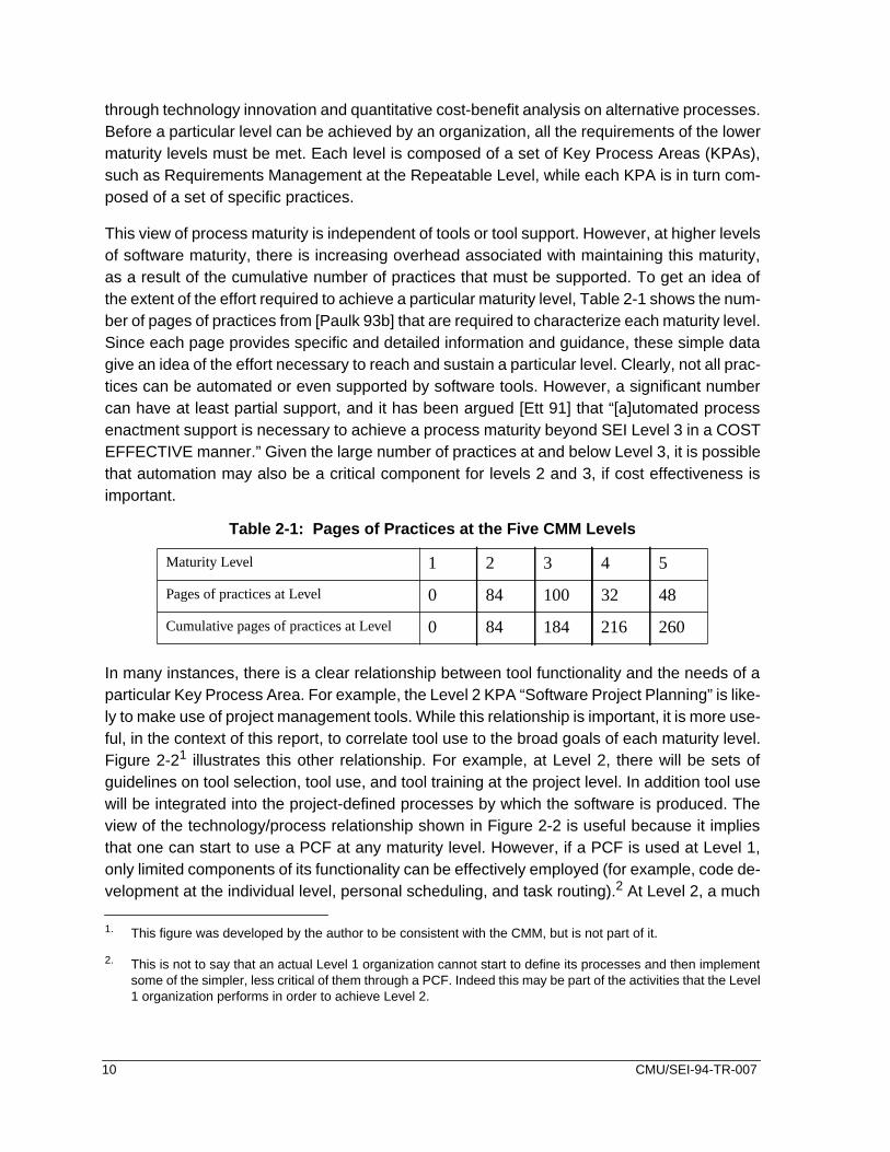
This view of process maturity is independent of tools or tool support. However, at higher levelsof software maturity, there is increasing overhead associated with maintaining this maturity,as a result of the cumulative number of practices that must be supported. To get an idea ofthe extent of the effort required to achieve a particular maturity level, Table 2-1 shows the num-ber of pages of practices from [Paulk 93b] that are required to characterize each maturity level.Since each page provides specific and detailed information and guidance, these simple datagive an idea of the effort necessary to reach and sustain a particular level. Clearly, not all prac-tices can be automated or even supported by software tools. However, a significant numbercan have at least partial support, and it has been argued [Ett 91] that “[a]utomated processenactment support is necessary to achieve a process maturity beyond SEI Level 3 in a COSTEFFECTIVE manner.” Given the large number of practices at and below Level 3, it is possiblethat automation may also be a critical component for levels 2 and 3, if cost effectiveness isimportant.
In many instances, there is a clear relationship between tool functionality and the needs of aparticular Key Process Area. For example, the Level 2 KPA “Software Project Planning” is like-ly to make use of project management tools. While this relationship is important, it is more use-ful, in the context of this report, to correlate tool use to the broad goals of each maturity level.Figure 2-21 illustrates this other relationship. For example, at Level 2, there will be sets ofguidelines on tool selection, tool use, and tool training at the project level. In addition tool usewill be integrated into the project-defined processes by which the software is produced. Theview of the technology/process relationship shown in Figure 2-2 is useful because it impliesthat one can start to use a PCF at any maturity level. However, if a PCF is used at Level 1,only limited components of its functionality can be effectively employed (for example, code de-velopment at the individual level, personal scheduling, and task routing).2 At Level 2, a much
1. This figure was developed by the author to be consistent with the CMM, but is not part of it.
2. This is not to say that an actual Level 1 organization cannot start to define its processes and then implementsome of the simpler, less critical of them through a PCF. Indeed this may be part of the activities that the Level1 organization performs in order to achieve Level 2.
Table 2-1: Pages of Practices at the Five CMM Levels
Maturity Level 1 2 3 4 5
Pages of practices at Level 0 84 100 32 48
Cumulative pages of practices at Level 0 84 184 216 260
10 CMU/SEI-94-TR-007

(1) INITIALIndividualistic, craftsman-like approach used.No guidelines or standards in the use of tools.No metrics gathered.No support of reuse.High quality product produced only by skilled craftsmen.Effective software production limited to small teams.
(2) REPEATABLEProject-level commonality in use of tools.Some team-oriented tool-to-tool integrations performed.Some local metrics gathered/analyzed (level of effort).Project standards on tool use specified.Training in use of project tools given.Some limited reuse of designs and code.
(3) DEFINEDTool standards are set across the organization.Local tool selection is based on organizational standards.Repository for organizational data established.Corporate reuse library established.Metrics gathered based on organizational standards.Metrics stored in org. repository -- for trends, profiling.Organizational tools training standards established.
(4) MANAGEDProcess improvement is driven by quantitativeanalysis of metric data.
(5) OPTIMIZINGInnovative tools and technologies evaluat-ed for and adopted into the organization.
Figure 2-2: Tool-Use Characteristics at the Five Maturity Levels
CMU/SEI-94-TR-007 11

broader set of functionalities can be invoked, since project processes can be enacted throughthe PCF.
2.3 Why Use a Process-Centered Framework?
PCFs represent a new class of software that integrates the people in the organization with thedevelopment process and with the supporting technology. Unlike compilers, editors etc., PCFsprimarily affect how work is performed rather than what is produced. PCFs provide the “glue”that actively manages the flow of work between people and their tools. Thus the issues thatmust be addressed in their adoption are significantly different from those for standard CASEtools. Some of these issues are already known through experiences with the software factoryconcept [Cusumano 91], but there may be novel issues that, because of the lack of practicalapplication of PCFs in real-world settings, we have yet to discover. The primary motivationsfor using a PCF are improvement of quality and productivity; each of the items discussed be-low directly supports these goals. There are some significant advantages to using a PCF andsome disadvantages. These are also discussed below.
2.3.1 Advantages of Using a PCF
Use of a PCF inherently forces one to define one’s processes in a rigorous enactable sense.This discipline alone is a major benefit. It allows for improved communication and understand-ing between the human participants and for consistency in how things are done. While use ofa PCF cannot guarantee process improvement, used correctly it can certainly support the im-provement effort by encouraging process definition and use. Training new employees in theprocess [Kellner 89] is supported both off-line and on-line. off-line support is available throughuse of the defined model to teach the novice the overall structure of the process. On-line, thenovice (like other parties using the process) is guided through the process and thus requiresa less detailed knowledge of the process in order to do his/her job effectively. In this way, fewerprocess-related errors are likely to be made. Whether the user is a novice or not, a PCF caneliminate the need for project personnel to perform many mundane tasks. Automated actionscan be initiated on the basis of certain process states being reached, information can be pre-sented to the user when appropriate, and messages can be sent between agents (human ornot) when necessary.
As a by-product of having one’s processes defined in an enactable sense, one can build upan enactable-process reuse library. This library can be of enormous help to others in the or-ganization who have similar process needs [Kellner 93b]. Thus a project that has developeda particularly effective process (say, for peer review) can save the process in the corporatereuse library for access by others. By so encouraging this consistency and uniformity of pro-cess use, the organization is not only saving resources, but it is supporting Maturity Level 3characteristics.
12 CMU/SEI-94-TR-007

If a process cannot be measured, then improvement is a matter of opinion. However, collect-ing metric data manually has several drawbacks. First, developers generally do not want towaste their time manually filling out metric data forms, for either time-dependent data or code-dependent data, if they see no direct benefit to their work. Second, manually-generated datais likely to be error-prone and inconsistent,3 particularly if the data is collected with resentmentand suspicion. Resentment and suspicion are related to the issue of intrusiveness, that is,management “spying” on developers and using the collected data as fodder for job evalua-tions. However, this problem exists whether a PCF is used or not. (Suggestions for its solutionare addressed later in Section 8.2.) Metrics collection and analysis can be major time consum-ers, and use of automation in this area could thus be a significant contributor to productivity.Of course, the collection of complete and accurate data also enhances product quality. Anal-yses of this metric data should lead to improved automated processes, and these improve-ments can then be permanently captured in the corporate reuse library.
In a traditional software development organization, it is often difficult for management to obtaincurrent information on project status, etc., particularly if the project is large. Since the automat-ed control of a process requires a current knowledge of task and product status, decisions tak-en etc., this information can also be made immediately available to management. Thusmanagement can request reports on such current information as “list of tasks completed” or“status of change requests”.
An indirect advantage of PCFs is that they may make CASE technology more effective. Earlierit was mentioned that CASE tools are too often viewed at a tactical level, that is, organizationalissues such as process adoption and improvement are not seen as important elements to suc-cess. However, PCFs force one to address these very issues. Thus embedding CASE toolsinto a PCF may provide those CASE tools with a context to make them more effective.
2.3.2 Disadvantages of Using a PCFBesides the significant advantages described above, there are some potential pitfalls to usinga PCF. First, not all software development organizations have characteristics compatible withhigh degrees of process automation. This is particularly true for organizations in which con-ceptually new software is being developed. These organizations may not easily be able to sta-bilize their processes and may have to operate in a craft manner (i.e., using small teams ofhighly competent professionals).
Second, the notion of letting a machine control how one works has negative connotations as-sociated with mindless mass production. Designing an automated process to be human-com-patible, while challenging, is critical to success. Thus, in addition to understanding themechanics of building process programs, the designer of these processes must have insightsinto human behaviors, motivations, and expectations, and must be sensitive to the needs ofthe project for which the processes are being developed. As will be discussed later, it is prob-
3. Of course, automated collection of metrics can be prone to its own types of errors, for example, if the durationof a task is equated with the task effort.
CMU/SEI-94-TR-007 13

ably essential for success that those who will use the automated processes should also beinvolved in their design. While management may see process automation as a means to con-trol the developers (through, for example, greater access to status information), developerswill only accept such automation if it is perceived to support their developmental needs (e.g.,it liberates from chores rather than enforces unrealistic constraints). An example of a badlydesigned system might be one in which management can too easily spy on the minute-to-minute activities of developers.
Another pitfall in designing automated process models is the inability to handle unanticipatedevents. For example, the model may have to be modified during the project’s execution in or-der to handle extra staff. Such events will surely occur. Thus, PCFs should contain mecha-nisms to allow the process designer to adapt processes during their real-time execution.Because this activity may introduce erroneous process behavior, such modifications can havepotential danger and must be managed very carefully. In addition, there may be even moresevere situations from which it is not possible to revert to an automated process. For thesecases, built-in mechanisms to allow the process model to gracefully degrade to manual controlshould be considered.
A practical but important consideration is what might be called “process roll-back”. Situationsmay occur, for example, where a technical error is made and not caught at the time. The pro-cess moves forward, and later on the problem is identified. With a non-automated process,there is likely to be sufficient flexibility within human control, so that manual corrections can bemade. However, with the automation of a predefined process, reversing back to correct theproblem will be much more difficult. In the simple case of a wrong button being pressed, an“undo” feature will be sufficient, but after a sequence of permanent changes have been com-mitted, the complexity of the fix is much higher. Currently, the only practical solution may beto take the automated controller off-line, fix the problem manually, and then restart the control-ler.
14 CMU/SEI-94-TR-007

3 An Experimental Investigation into PCFs
In order to better understand the technology behind process-centered frameworks, two prod-ucts are examined. These products are ProcessWeaver, developed by Cap Gemini [Process-Weaver 92], and SynerVision, developed by Hewlett-Packard [SynerVision 93a, SynerVision93b]. These are typical of a new generation of commercially available products that have re-cently become available. Information to contact the suppliers of these and other PCFs4 canbe found in Appendix A.
3.1 The Experimental Approach
To compare the technologies behind ProcessWeaver and SynerVision, a modified version ofan evaluation methodology, developed for software engineering environments, is used [Wei-derman 86]. This evaluation technique is based on several criteria which, in the context of thisinvestigation, involve the following:
• Since detailed functionality may vary from PCF to PCF, the evaluationattempts to focus on the activities of the users of a PCF rather than the low-level features implemented in that PCF.
• The evaluation postpones the inspection of specific features of a PCF as longas possible. This approach forces one to keep a broad perspective and thishelps with comparisons of PCF functionalities (as opposed to detailedimplementation).
• The evaluation is based on a PCF-independent example of a process. Thisensures that the PCFs are being assessed against the same criteria. It alsoreduces the effort since the same process model is used on each PCF.
• Objectivity and repeatability are assured through performing the same welldefined tests on each PCF. Different experimenters, using the same processexample, should come to the same or similar conclusions when evaluatingthe same PCF.
• Prior to examining the PCF, it may not be possible to determine allappropriate aspects of the evaluation.Thus the experimental approachshould allow for iteration and refinement of the approach during theevaluation.
• The methodology should be extensible in the sense that the experiments canbe easily modified, expanded and improved upon.
The original approach suggested by Weiderman focuses on end users. Such an application toproject management tools is discussed in [Feiler 88]. However, in evaluating PCFs, there aretwo classes of user: the developer of the enactable process and the subsequent end-user ofthis process. Thus, the approach is modified somewhat to account for this difference. In addi-
4. Since SynerVision has some end-user applications built into it, it has some of the characteristics of a process-centered environment (PCE). However, for simplicity, both ProcessWeaver and SynerVision will be called pro-cess-centered frameworks (PCFs). See Appendix D for an elaboration of this issue.
CMU/SEI-94-TR-007 15

tion, some of the original methodology has been simplified. These simplifications result in lessformality and detail in the areas of evaluation questions than suggested in Weiderman’s ap-proach.
While Weiderman’s approach involved six phases, the approach used here involves eightshorter phases. The details of these phases and the relationships between them are illustratedin Figure 3-1. The vertical line down the center of Figure 3-1 separates the development of the
PCF-independent experimental set-up (Phases 1 through 4) from evaluations of each PCF(Phases 5 through 8), while the arrows represent dependencies. For example, Phase 1 pro-vides Phase 3 with criteria on what is needed in the process model. A textual description ofeach phase is given below.
1. Establish model-building criteria. Establish the functional capabilities againstwhich the PCFs are evaluated. This includes both the capabilities fordeveloping and debugging process programs based on the process example.For example, we may wish to investigate the ability of the PCF to model thecommunication between agents (human or otherwise) or the ability of thePCF to perform syntax checking of the process program.
2. Identify end-user capabilities. Identify end-user capabilities that the PCFsmight provide. Examples are: personal task management, project planning,or metrics collection. In reviewing these capabilities, one has to be careful notto conclude that product A is better than product B because it includes tool X.One design philosophy may result in a suite of tools being integrated into theproduct, while another design philosophy may focus on providing processmechanisms together with the capability for encapsulating tools.
Run end-user
Figure 3-1: Simplified Evaluation Process
Phase 1
Phase 2
Phase 4
Phase 3
Phase 5
Phase 6
PCF-Independent Products PCF-Dependent Products
Identify end-user
Develop evaluationcriteria and questionnaire
Develop processexample and its execution
Implement processexample in PCF
Evaluate developerand end-user results
Evaluate end-userrole-plays
Phase 7
Establish model-building criteria
capabilities
Phase 8
script simulations
16 CMU/SEI-94-TR-007

3. Develop process example. Given the information of Phases 1 and 2, developthe process example against which the PCFs are to be tested. The processexample developed for the evaluation is a document-modification processand was graphically defined using ProNet [Christie 93b]. Details of thisexample, which will be discussed below, is defined independently of the PCFon which it will later be implemented. An execution script is also developed toguide the end users through the end-user simulations (see Phase 7).
4. Develop evaluation criteria and questionnaire. Develop a set evaluationcriteria, that are independent of both the PCFs and the process example, andagainst which both the developer and end-user evaluations will be performed.The criteria used are very similar to those identified in [Weiderman 86] andconsist of such items as “ease of learning”, “performance”, “portability”, etc.Also develop a questionnaire to be filled in by the role players of the end-usersimulation.
5. Implement the process example in the PCF. In each PCF, implement theprocess example defined in Phase 3, using the Phase 1 criteria for guidancein the building process.
6. Evaluate developer results. With the experience gained from the PCF-specific model-building exercise (Phase 5), assess the capabilities of thePCF using the evaluation criteria developed in Phase 4, supported by themodel-building criteria of Phase 1.
7. Run end-user simulations. Perform a set of end-user evaluations, in whichseveral persons act out the process enactment scenario. These simulationswill be guided by the execution script. A copy of the materials provided to theend-users (including the execution script) is provided in Appendix E.
8. Evaluate end-user role plays. Analyze the end user role-plays using thePhase 4 evaluation criteria. Also use the Phase 4 evaluation criteria toaddress end-user issues that are not part on the end-user process enactmentscenario.
The next four subsections describe respectively the first four phases (i.e., the PCF-indepen-dent phases) of the of the experiment.
3.2 Model-Building Capabilities (Phase 1)
In order to define the process example, a set of features that a PCF may be expected to sup-port is identified. These features provide requirements for the design of the process exampleand are placed in the following categories given in Table 3-1: development, enactment, re-source, communications and debugging. The categories are similar to those identified in [NIST93] (See Appendix D). In addition, [Kellner 90] was reviewed in helping to identify some of theelements listed in Table 3-1.
CMU/SEI-94-TR-007 17

be
n
sup-
le to
ote
of,
e
il
i-
Table 3-1: Model-Building Capabilities
1 Development issues Discussion
a Scoping of variables If a process is composed of subprocesses, then there shouldmechanisms for passing variable values from process to sub-process and back.
b Modeling hierarchies Models of any realistic complexity cannot be defined as onemonolithic entity. Thus the PCF must allow activities to haveinternal structure (i.e., contain sub-activities) that can be brokeout and defined separately.
c Supporting model development In order to construct process models, the PCF must provideport for model building. This support may be through a textuallanguage with an editor, a graphical language, or a mixture oftext and graphics.
d Creating a process library In order to enact a process multiple times, it must be possibstore the process program (i.e., the template) with its variables(e.g., roles) uninstantiated. See also item 2.a.
e Supporting flexibility of task control Humans perform tasks in an opportunistic manner that cannalways be predicted by a process model. For example it may blegitimate to prepare for a task before all the formal precondi-tions for the task have been met (as defined in the processmodel). Thus the ability to specify differing degrees of controlover task initiation is desirable.
f Modeling standard programmingconstructs
The process modeling language in a PCF must have a meansexpressing the usual programming constructs such as iterationconditional testing, and variable instantiation.
g Performing parallel, aggregatedprocesses
Consider the situation where twenty identical processes feed adownstream process. The PCF should have the ability to invokthe same template for all twenty upstream processes. Further,because the number of upstream tasks may not be known untrun-time, it would be helpful if binding of these could bedelayed until that time.
2 Enactment issues Discussion
a Assigning agents to roles A PCF must be able to distinguish between roles (usuallydefined in the process model prior to run-time) and the agentswho actually perform the actions (defined at the start and possbly throughout process enaction). The concept of roles andagents applies equally to humans and machines. The ability toinstantiate roles with specific agents must be supported.
18 CMU/SEI-94-TR-007

si-
s
be
and-ns
.
onsans
ro-
ion.
g-
b Supporting on-the-fly process modi-fication
The ability to modify process models on the fly during executionmay be important. Things go wrong during process execution,and changes may have to be made promptly. It may not be posble to wait until an automated process has terminated beforemodifying action can be taken.
c Logging process data Logging of process can be important in order to:1) debug the process (see also item 5.g),1) roll back an ongoing process to correct an error,2) provide post-project verification that the defined process wafollowed, and3) provide insights for the support of process improvement.
3 Resource issues Discussion
a Invoking tools A PCF must provide the mechanisms through which tools caninvoked. Such invocation may involve simply starting the tool orit may involve accessing a specific aspect of its functionality.
b Managing objects There is a close relationship between the tasks in a process the artifacts produced by the tasks. These artifacts may be versions of a product. Thus, having some means to manage versioof products is a useful capability.
4 Communication issues Discussion
a Modeling communication betweenagents
Central to process enaction is the notion of communication,either from human-to-human, human-to-computer-agent, com-puter-agent-to-human and computer-agent-to-computer-agentThe PCF must provide mechanisms for such communication.
b Modeling automatic actions As a result of an event occurring, automatically triggered actimay be necessary. These actions may send messages to humor may trigger other automatic events. Means to model auto-matic actions must therefore be provided.
5 Debugging issues Discussion
a Checking syntax This is the ability to identify and clearly define the source of pgramming errors.
b Performing reachability analysis This is the ability to evaluate an enactable process model toassure that all of its parts are accessible during process enact
c Performing deadlock analysis This is the ability to evaluate if there are process states fromwhich it is impossible to exit.
d Tracing process dynamics The ability to trace the dynamics of the process as it is beinenacted can provide significant insights for process model validation.
Table 3-1: Model-Building Capabilities
CMU/SEI-94-TR-007 19

o-
-
eekly
on
sks,them.and
elp.
.s.
3.3 End-User Capabilities (Phase 2)
End-user applications may be built in (as part of a PCE) or through the invocation of externaltools (as in a PCE or PCF). In either case, application tools will be needed to support the largemajority of processes. Some of the capabilities which are particularly well suited to integrationin a PCF or PCE are reviewed in Table 3-2.
3.4 Process Example and Its Execution Script (Phase 3)
All of the items in Table 3-1 (with the exception of debugging issues) influenced the design ofthe process example in some significant way. This example portrays a simple document up-date process and is formally defined using ProNet notation [Christie 93a, Christie 93b, Earl93].5 A brief review of this notation is also provided in Appendix C. The elements of the exam-ple, illustrated in Figures 3-2, 3-3, and 3-4, are described below.
5. Note that the ProNet graphical symbol set used in the first two of these documents is more limited than usedin this report (see Appendix C for current symbol set).
e Querying This is the ability to check on the values of variables during prcess enactment (simulation or actual use).
g Spying This is the ability to insert breakpoints in the simulation of a process in order to examine the status of variables, etc.
g Logging process data See 2.c above.
Table 3-2: End-User Capabilities
Application Discussion
a Scheduling periodicwork
A simple but important application of process support is the ability to initiattasks (e.g., time card generation) or present personal reminders (e.g., wemeetings) on a periodic basis.
b Collecting metricdata
A PCF provides many mechanisms which can facilitate the automatic collectiof process and product metrics.
c Supporting projectmanagement tasks
Both process enactment and project management require information on taresources, and agents and the relationships and dependencies between Thus there is significant overlap in the data needs of process enactment project management and each can leverage off the other.
d Supporting theindividual user
There are many modest personal tasks with which process automation can hExamples include: managing “to do” lists, planning work estimates, trackingwork effort, and capturing personal metrics.
e Supporting groupcommunications
A variety of group activities do not require a full process model to drive themExamples include: delegating, negotiating, reassigning and coordinating task
Table 3-1: Model-Building Capabilities
20 CMU/SEI-94-TR-007

The group that performs the document modifications consists of a manager and two technicalwriters. Following the process flow, shown in Figure 3-2, the manager receives a change re-quest (CR) from outside and determines through the process review new CR, if it is appropri-ate for processing. If it is, then there is a selection process, identify agents for roles, thatdetermines who will perform the editing function and who will perform the review function. Fi-nally there is the update process, update document, in which the changes are actually made.The latter two processes have lower level detail, and this exercises the PCF in the ability tomodel hierarchies.
The identify agents for roles process, shown in Figure 3-3, contains elements to exercise com-munication and automatic action facilities in the two PCFs. The manager makes an initial as-signment of roles (make initial assignments), and these roles are communicated to the two
Figure 3-2: The Modify Document Process
review new CR
identify agents for roles
update document
accepts | falseaccepts | true$newCR
DO
$manager
editopr notified
has exit composite
has exit conditionhas exit condition
has entrance agent
has entrance condition
has entrance artifact
has exit condition
has exit condition
has entrance condition
msgSent
CMU/SEI-94-TR-007 21

Figure 3-3: The Identify Agents for Roles Process
get editor's reply
impose assignments
notify reviewer
notify editor
accepts| true
DO
edAccepts | i,false
$techWriter2
assignments made
$manager
$manager
make revised assignments | i++
i == 1
i == 2
editor notified
CO
has entrance agent
has entrance agent
has exit condition
has entrance condition
has entrance agent
has exit condition
has entrance agent
has exit agent
has entrance
has entrance condition
has exit condition
has entrance condition
has entrance condition
has entrance composite
has exit composite
$editor
has exit agent
has entrance
has entrance condition
has entrance condition
has exit condition
reviewer notified
make initial assignments | i=1
$editor
role assigned | i
$editor
has exit agent
has exit condition
has exit agent
has exit agent
$reviewer
$reviewer
has exit agent
has exit agent
$techWriter1 $techWriter2
has entrance agent has entrance agent
condition
condition
$techWriter1
has entrance agent
$editor
$techWriter1
$techWriter2
has entrance agent
has entrance agent
has entrance condition
$reviewer
$reviewer
has entrance agent
has entrance agent
has exit conditionedAccepts | i,true
$newCR
has entrance artifact
22 CMU/SEI-94-TR-007

individuals. The person assigned the editor role can accept or reject that role (get editor’s re-ply). If the reply is “accept”, then the other person is automatically notified through the notifyreviewer activity that he/she has been given the reviewer role. If the first person rejects theeditor role, then the second person is automatically requested to take on the editor’s role
Figure 3-4: The Update Document Process
get doc
modify doc | i=1
review doc
$editor
$document | 0
$document | i
DO
$comments | i-1
docRepos
docReposeditor notified
has entrance store
has exit artifact
has exit artifact
has entrance artifact
has exit composite
has exit
has entrance store
has entrance artifact
has entrance artifact
has entrance agent
has entrance condition
$newCR
put doc
has entrance artifact
modify doc again | i++
$editor
has entrance agent
$newCR
has entrance
has exit
has entrance artifact
docSaved
has exit condition
sendMsgToMgr
has entrance
msgSent
has exit artifact
$document | i
has entrance artifact
has exit condition
condition
passReview
has exit artifact
has entrance artifact
has entrance condition
condition
has entranceartifact
artifact
artifact
$comments | i
$reviewer
has entrance agent
CMU/SEI-94-TR-007 23

(make revised assignments). This person can also accept or reject the editor’s role. If “reject”is selected, then the manager is notified and a manual assignment is made through the activityimpose assignments. In this case the writers are notified of the manager’s decision (throughthe notify editor and notify reviewer tasks).
The remaining high level process, update document, is shown in Figure 3-4. To perform thetasks in this process, the document is removed from a simple repository, edited, reviewed, andthen replaced into the repository. Thus some simple SCM functionality is required. The pro-cess starts with the system extracting the document from the repository and presenting it tothe editor (get doc). The editor then revises it as described in the change request (modify doc).After the modified text has been reviewed (review doc), the document is then either approvedby the reviewer or sent back to the editor with review comments for further modification togeth-er. If the reviewer approves the changes, the document is put back into the repository and themanager is notified that the process is complete (put doc).
Note that items 1a, 1b, 1c,1d, 1f, 2a, 3a, 3b, 4a, and 4b of Table 3-1 are explicitly tested bythe process example. It should also be noted that there are many aspects of the two PCFsbeing addressed that are not being tested. For example, both PCFs have significant capabilityin the area of external communication and tool encapsulation.
The execution script for the process example is now reviewed. Appendix E provides the eval-uation materials which were given to the participants of the end-user evaluations. This script,which is part of the end-user evaluation materials, is shown in Table E-1 and follows one ofmany possible process scenarios. In this particular scenario, the manager receives an incom-ing change request to modify a document (item 1 in Table E-1) and identifies his initial choiceof editor (item 2). Both technical writers (A and B) initially refuse to accept the role of editor(items 3 and 5), and this forces the manager to impose the editor role on Technical Writer A(items 7). After Technical Writer A has performed the requested modification (item 10), thedocuments are sent for review to Technical Writer B who in turn adds a comment in the sup-porting document Review Comments (item 11). The task is then automatically sent back toTechnical Writer A who again edits the document (item 12), after which it is sent back to Tech-nical Writer B for a second review. At this point, Technical Writer B accepts the modification(item 13), the document is automatically saved in the repository, and the manager is notifiedthat the modification has been successfully completed (item 14).
24 CMU/SEI-94-TR-007

3.5 Evaluation Criteria and Questionnaire (Phase 4)
In order to assess the adequacy of the two PCFs, a set of evaluation criteria are established.These criteria are defined independently of the model-building capabilities (Phase 1) and theprocess example (Phase 2). They are, in fact, a modification of the set suggested in [Weider-man 86], and are shown in Table 3-3. These form the basis for the evaluation which the author
performed. Also, an end-user questionnaire is developed. This questionnaire, shown in TableE-2, lists the questions that the role players answered after performing in the simulated docu-ment update process. An analysis of the responses to these questions is provided in Section6.
In summary the sequence of tasks that will be performed using SynerVision and Process-Weaver is as shown in Figure 3-5.
Table 3-3: PCF Evaluation Areas
1 Functionality a) Completeness of major functional areas for develop-ment, as identified in Tables 3-1.b) Completeness of end-user functional areas as definedin Table 3-2.
2 Developer issues a) Ease of learning.b) Ease of use.c) Effectiveness of support for development.d) Quality of on-line help.e) Error handling.
3 End-user issues a) Ease of learning.b) Ease of use.c) Clarity of presentation.
4 Performance a) Execution time efficiency.b) Space efficiency.
5 System interface a) Ease of tool integration.b) Portability.c) Interface to operating system.
6 Off-line user support a) Support from customer representatives.b) Clarity of documentation.c) Availability of hands-on training.d) Availability of encoded process examples.
CMU/SEI-94-TR-007 25

Implement the process example in the PCFs
using the specifications of Figures 3-2, 3-3 and 3-4)
Evaluate issues identified in
Evaluate end-user responses to role plays (Table E-2)
Perform end-user role plays
Figure 3-5: Sequence of Evaluation Tasks
(results evaluated in Section X.3*)
(results evaluated in Section 6)
* where X=4 for ProcessWeaver and X=5 for SynerVision
Table 3-3, supported byTables 3-1 and 3-2
(model-building guided by Tables 3-1, and 3-2
(Tables E-1 and E-2)
26 CMU/SEI-94-TR-007

4 The ProcessWeaver Experiment
4.1 Review of ProcessWeaver
ProcessWeaver provides a suite of tools for the management of individual tasks and for pro-cess automation (i.e., sequences of tasks). The end user of ProcessWeaver is provided witha main window called the Agenda, and it is through this window that tasks, called Work Con-texts, are sent, received, or worked on. Work Contexts appear as icons in the Agenda and canbe opened to provide detailed tasking information. In addition, there are several windows tosupport the development of processes. These are the Method Editor, the Activity Editor, theCooperative Procedure Editor, and the Work Context Editor. The Method Editor provides thecapability for defining activity hierarchies, while the Activity Editor allows task inputs, outputs,and roles for these activities to be specified. Through the Cooperative Procedure editor, onecan model the detailed task-level processes for each activity. Finally, the windows throughwhich the end user performs tasks, are designed using the Work Context Editor. These ele-ments of ProcessWeaver are reviewed in more detail in the following subsections. The finalsubsection (4.1.6) provides an “integration” view, since there are many components to Pro-cessWeaver and the relationship between these components is not at first obvious.
4.1.1 Agenda WindowThe Agenda window acts as a central location for managing an individual’s tasks. The currenttasks are displayed as icons in the Agenda window as shown in Figure 4-1. In this instance,the task UpdateDocument is the Work Context icon. These tasks may either be isolated “todo’s” or may be elements of a more complex process. If they are isolated “to do’s”, they maybe delegated from someone else or they may originate locally from the person who “owns” thatAgenda. In the latter case, the Work Context could reflect a personal task that has to be per-formed on a periodic basis (e.g., defining monthly objectives) and automatically appears onthe first day of the month. Delegation of a task is performed simply by dragging the Work Con-text icon over to the Delegation icon (the report) on the right of the window. This generates apredefined list of candidates, from which one or more are selected. A completed task can beeliminated by dragging its icon over the garbage can icon.
The menu bar along the top of the window provides a variety of options. The Weaver optionallows one to access the editors for Work Contexts, Cooperative Procedures (i.e., processes),and Methods (i.e., activity hierarchies). The Work Context option primarily allows one to selectindividual Work Contexts to be instantiated for a specific task and perhaps delegated. The Pro-cedures option allows one to generate a new instance of a process, while the Preferences op-tion allows one to customize some setup parameters, such as setting an alarm when a WorkContext is received.
CMU/SEI-94-TR-007 27

4.1.2 Work Context WindowOn double clicking a Work Context icon in the Agenda window, its associated window ap-pears. A typical Work Context window is shown in Figure 4-2. Notice that there are three dif-ferent types of objects. These are: message boxes, icons representing elements of the task tobe worked on, and control buttons. These three items are all the object types that need to besupported by Work Contexts. In the message box, variables can be embedded in the text.Thus in the example above, a role variable (e.g., $person) can be instantiated at run-time witha name (e.g., Alan). These boxes can also be used to input information into the process. Byclicking on an icon, the user can activate the corresponding object. This could be a text editor,compiler, or CASE tool.
Individual Work Contexts can be developed or modified using the Work Context editor. Thisfunction allows the developer to customize Work Contexts with any combination of text boxes,icons and buttons that is appropriate to support the end user. A wide variety of icon designsis provided, and one can associate an icon with an appropriate tool or document. A default toolset is provided and this set can be extended by the developer if necessary. Buttons are givenidentifiers so that they can be associated with a particular decision path of a process model.
Figure 4-1: An Agenda Window
28 CMU/SEI-94-TR-007

4.1.3 Method EditorAs mentioned above, the two previous views (the Agenda and the Work Context) support theend user of the process while the next three views (the Method, Activity, and Procedure Edi-tors) support the process developer. ProcessWeaver models projects by structuring them intoa hierarchy of activities. An example of a simple hierarchy is shown in Figure 4-3. The windowin Figure 4-3 supports a variety of functions. First through the Edit option one can add, delete,and append both activities and decomposition levels to the hierarchy. Through the Check op-tion one can examine measures related to, for example, the consistency of input and outputproducts between activities, and this can be very useful for the verification of large models.The Run-time option allows one to generate simple default cooperative procedures (process-es) automatically that are attached to the activities; these are discussed in Section 4.1.5. Eachof the activities has associated with it an Activity Editor that defines the inputs required by thatactivity, the roles required to support the activity, and the outputs generated by that activity.
Figure 4-2: A Work Context Window
.
CMU/SEI-94-TR-007 29

4.1.4 Activity EditorEach Activity Editor window displays information related to one activity; a typical Activity Editorwindow can be seen in Figure 4-4. This window can be accessed for a particular activity bydouble clicking on that activity in the Method Editor window. The main items displayed in theActivity Editor window are the inputs, outputs, and roles associated with the activity. It is theseitems against which the Methods Editor can perform consistency checking, over the wholeprocess model, as discussed in Section 4.1.3. By clicking on the Edit button, one activates theCooperative Procedure Editor window.
4.1.5 Cooperative Procedure EditorThe Cooperative Procedure window defines the detailed processes using a Petri net [Reisig82] notation. A very simple default process model is illustrated in Figure 4-5. Petri Nets wereinitially developed to model synchronous and asynchronous events in communication sys-tems and have been adapted by ProcessWeaver for process definition and enactment. Thesenets consist of three kinds of elements that can be displayed graphically: places (denoted bycircles), transitions (denoted by rectangles), and directed arcs. Arcs connect places to transi-tions and transitions to places. In addition, the concept of tokens (that are inserted into places)is used for process enaction to mark a place that has been asserted in some way (e.g., madeTRUE). If a token is in a place, then all the arcs emanating from that place are said to be load-ed, and if all the places leading to a transition have tokens, then the transition is said to beenabled. Within this process context, transitions represent state changes while places repre-sent states. Thus, when a condition is satisfied, and the associated action taken, the processcan transition from one state to the next.
Figure 4-3: A Method Editor Window
30 CMU/SEI-94-TR-007

In Figure 4-5, the process begins at the place with the inserted token. An event at the nexthigher level in the activity hierarchy may initiate this sub-task. The Perform_Update transitionhas no entrance condition. The window associated with the action (not shown) provides threeelements. First, actions can be taken by executing some code written in ProcessWeaver’s Co-shell scripting language. Second, the agent who will perform the action is identified. Finally,
Figure 4-4: An Activity Editor Window
CMU/SEI-94-TR-007 31

the Work Context, that will be sent to the agent, is identified. When the agent has finished thework, the Done button (defined in the Work Context) is pressed, and the token moves to theplace marked END.
Figure 4-5: A Cooperative Procedure Window
32 CMU/SEI-94-TR-007
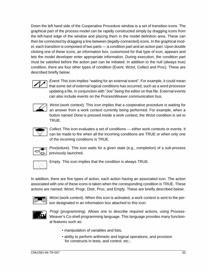
Down the left hand side of the Cooperative Procedure window is a set of transition icons. Thegraphical part of the process model can be rapidly constructed simply by dragging icons fromthe left-hand edge of the window and placing them in the model definition area. These canthen be connected by dragging a line between (legally-connected) icons. In the graphical mod-el, each transition is composed of two parts — a condition part and an action part. Upon doubleclicking one of these icons, an information box, customized for that type of icon, appears andlets the model developer enter appropriate information. During execution, the condition partmust be satisfied before the action part can be initiated. In addition to the null (always true)condition, there are four other types of condition (Event, Wctxt, Collect and Proc). These aredescribed briefly below:
Event: This icon implies “waiting for an external event”. For example, it could meanthat some set of external logical conditions has occurred, such as a word processorupdating a file, in conjunction with “Joe” being the editor on that file. External eventscan also include events on the ProcessWeaver communication bus.
Wctxt (work context). This icon implies that a cooperative procedure is waiting foran answer from a work context currently being performed. For example, when abutton named Done is pressed inside a work context, the Wctxt condition is set toTRUE.
Collect. This icon evaluates a set of conditions — either work contexts or events. Itcan be made to fire when all the incoming conditions are TRUE or when only oneof the incoming conditions is TRUE.
Proc(edure). This icon waits for a given state (e.g., completion) of a sub-processpreviously launched.
Empty. This icon implies that the condition is always TRUE.
In addition, there are five types of action, each action having an associated icon. The actionassociated with one of these icons is taken when the corresponding condition is TRUE. Theseactions are named: Wctxt, Progr, Distr, Proc, and Empty. These are briefly described below:
Wctxt (work context). When this icon is activated, a work context is sent to the per-son designated in an information box attached to this icon.
Progr (programming). Allows one to describe required actions, using Process-Weaver’s Co-shell programming language. This language provides many function-al features such as:
•manipulation of variables and lists,
•ability to perform arithmetic and logical operations, and provisionfor constructs in tests, and control, etc.;
CMU/SEI-94-TR-007 33

• communication with users through work contexts;
• manipulation of events on ProcessWeaver’s communication bus throughconstructs that are similar to Hewlett Packard’s Broadcast Message Server;and
• support for development of user-defined Co-shell functions.
Distr (distribution). This icon allows for the sending of a work context to multiplerecipients. Its behavior is similar to the Wctxt action.
Proc(edure). This icon initiates a sub-process of the current process at run-time.
Empty. This icon implies that there is no action.
4.1.6 Pulling the Elements TogetherGiven the number of elements that contribute to a ProcessWeaver model it can be a challengefor the novice to understand how all these elements tie together. Figure 4-6 provides a simpli-fied description of such an integrated picture. For the process developer, the Method Editorprovides a hierarchical view of the major activities. Each of the activities defined in the MethodEditor window has two associated windows: an Activity Editor that specifies the inputs, out-puts, and roles required for the activity, and a Cooperative Procedure Editor that defines thelower level elements of the process using the Petri net notation. Each transition in the Petri netis composed of a condition part and an action part, the action taking place when the conditionis met.
In the end-user view (at run-time), a process template is instantiated by a user (e.g., projectmanager) who invokes an existing Cooperative Procedure under the Procedures menu in theAgenda. This user does not see the Petri net process model, but is presented with a window(not shown) in which the roles, documents and other artifacts to be used in this specific pro-cess are instantiated. For example, the role $editor may be instantiated with the specific agent(e.g., Alan) who carries out the operation, while the file to be modified, $doc, may be instanti-ated by the document War and Peace. Upon receiving this information, ProcessWeaver canstart to enact the process (initiating Work Contexts, performing automatic tasks, etc.).
Through its activities, a cooperative procedure may perform a variety of types of functions.These were reviewed in Section 4.1.5. One of the important types of function is to be able tosend Work Context messages to human agents who are responsible for tasks. These mes-sages appear on the receiver’s Agenda window as Work Context icons. (In Figure 4-6, the taskis UpdateDocument.) On opening the icon to view the full Work Context window, the agentshould find sufficient information to perform the task. In the example shown in Figure 4-6, adocument icon (War and Peace) is seen on the Work Context window, and when this is
34 CMU/SEI-94-TR-007

Figure 4-6: Overview of ProcessWeaver Elements
Developer Views
End-user Views
Method Editor
Activity Editor
Cooperative Procedure Editor
Document Edit Window
Work Context WindowAgenda Window
CMU/SEI-94-TR-007 35

opened, the actual document to be worked on appears. Note that you can also open thechange request Too Long as well. When the task has been completed, the Done button on theWork Context window is pressed. This state change, resulting from pressing the button, is de-tected by the UpdateFinished condition in the Cooperative Procedure which then allows theprocess to move forward.
4.2 Developing the ProcessWeaver Process Model
To develop the ProcessWeaver model, it was originally intended that the activity hierarchyshown in Figure 4-3 be used. However, this had to be modified because of a variable scopingproblem that was encountered. It was intended that the persons taking on the roles of editorand reviewer be identified in the sub-activity IdentAgentsForRoles. However, as Process-Weaver is currently structured (in Version 1.2), a variable that is instantiated in a certain activ-ity can only have the instantiated value used in that activity or in child activities. Hence theactivity structure had to be simplified as shown in Figure 4-7. The activity ReviewIdentify in
Figure 4-7 thus includes the parent activity (DocUpdate) and the child activities (ReviewCRand IdenAgenForRoles) shown in Figure 4-3. The Cooperative Procedures for ReviewIdentifyand Update are shown in Figures 4-8 and 4-9 respectively.
The upper part of Figure 4-8 defines the process through which the manager reviews thechange request. To do this review, a Work Context is displayed on the manager’s terminal al-lowing the CR to be accessed for review and providing accept and reject buttons. Figure 4-8shows the two paths taken depending on his choice. The second part of the figure defines theprocess for selecting the editor and reviewer. The logic of this process is the same as that ofFigure 3-3, although the implementation is modified to conform with ProcessWeaver’s Petrinet notation. Note that this graphical model is not sufficient to completely define the processmodel; fragments of co-shell scripting are associated with many of the transition icons.
Figure 4-9 is a fairly straightforward adaptation of Figure 3-4. The document is checked out ofthe repository, modified by the editor, and sent to the reviewer. If the reviewer passes the doc-ument, the updated version is checked back into the repository. Otherwise, the modificationsare rejected by the reviewer, and the document is passed back to the editor with suitable com-ments in a review comments notebook. Check-out and check-in are implemented using the
Figure 4-7: Activity Hierarchy for the Example Process
36 CMU/SEI-94-TR-007

Figure 4-8: Cooperative Procedure for the Activity ReviewIdentify
CMU/SEI-94-TR-007 37

Unix SCCS commands get and delta that are embedded in the auxiliary Co-shell functionsshown in Figure 4-10. Libraries of such functions can be developed for general process useand are attached to a Cooperative Procedure for use within that Cooperative Procedure.
Notice at the end of Figure 4-8 that the subprocess Update (Figure 4-9) is initiated through aprocedure call to the action StartDocMod. The procedure EndDocMod watches for the termi-nation of this subprocess.
Figure 4-9: Cooperative Procedure for the Activity Update
38 CMU/SEI-94-TR-007
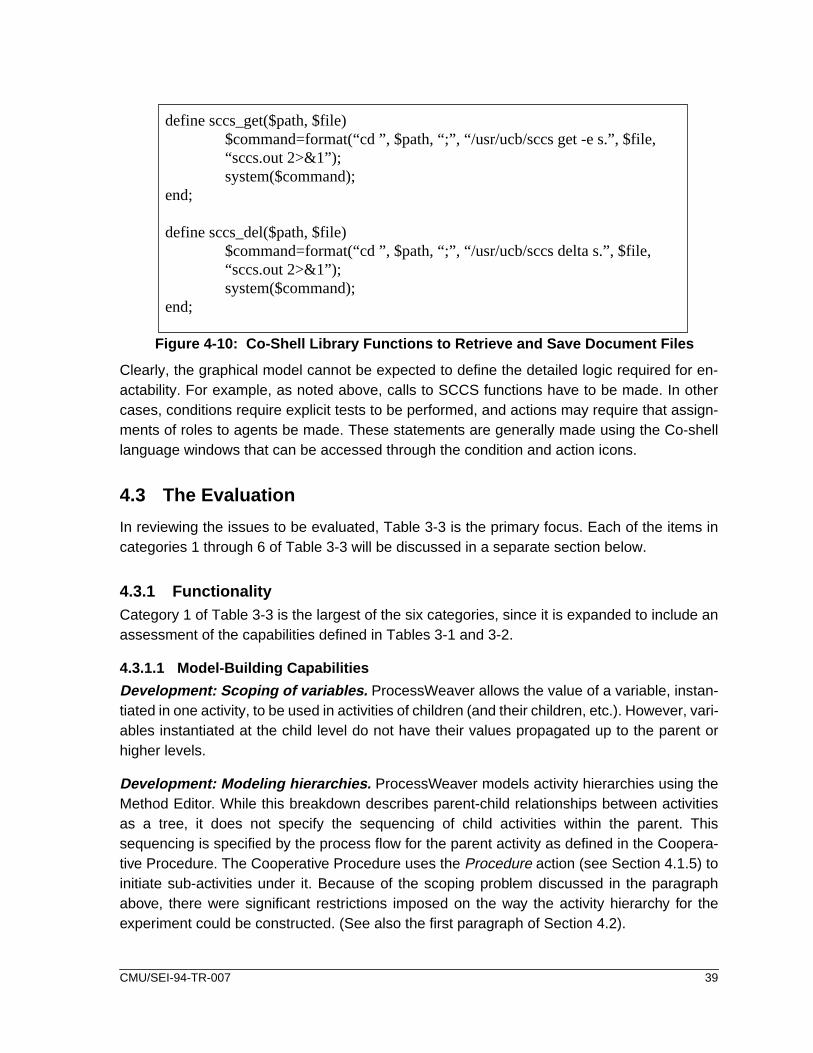
Clearly, the graphical model cannot be expected to define the detailed logic required for en-actability. For example, as noted above, calls to SCCS functions have to be made. In othercases, conditions require explicit tests to be performed, and actions may require that assign-ments of roles to agents be made. These statements are generally made using the Co-shelllanguage windows that can be accessed through the condition and action icons.
4.3 The Evaluation
In reviewing the issues to be evaluated, Table 3-3 is the primary focus. Each of the items incategories 1 through 6 of Table 3-3 will be discussed in a separate section below.
4.3.1 FunctionalityCategory 1 of Table 3-3 is the largest of the six categories, since it is expanded to include anassessment of the capabilities defined in Tables 3-1 and 3-2.
4.3.1.1 Model-Building Capabilities
Development: Scoping of variables. ProcessWeaver allows the value of a variable, instan-tiated in one activity, to be used in activities of children (and their children, etc.). However, vari-ables instantiated at the child level do not have their values propagated up to the parent orhigher levels.
Development: Modeling hierarchies. ProcessWeaver models activity hierarchies using theMethod Editor. While this breakdown describes parent-child relationships between activitiesas a tree, it does not specify the sequencing of child activities within the parent. Thissequencing is specified by the process flow for the parent activity as defined in the Coopera-tive Procedure. The Cooperative Procedure uses the Procedure action (see Section 4.1.5) toinitiate sub-activities under it. Because of the scoping problem discussed in the paragraphabove, there were significant restrictions imposed on the way the activity hierarchy for theexperiment could be constructed. (See also the first paragraph of Section 4.2).
Figure 4-10: Co-Shell Library Functions to Retrieve and Save Document Files
define sccs_get($path, $file)$command=format(“cd ”, $path, “;”, “/usr/ucb/sccs get -e s.”, $file,“sccs.out 2>&1”);system($command);
end;
define sccs_del($path, $file)$command=format(“cd ”, $path, “;”, “/usr/ucb/sccs delta s.”, $file,“sccs.out 2>&1”);system($command);
end;
CMU/SEI-94-TR-007 39

Development: Supporting model development. Process models are developed withgraphical notations to support high level decomposition of activities (through the Method Edi-tor) and to define the lower level process (through the Cooperative Procedure Editor). Both ofthese graphical views are supported by textual information that is input through forms linkedto the graphical editors. This graphical approach helps productivity by allowing a rapid devel-opment of the overall process model. In addition, fewer syntactic and semantic errors areintroduced in comparison to a purely textual approach. The graphical form of the model alsoallows for better communication with persons unfamiliar with process modeling.
Development: Creating a process library . ProcessWeaver stores processes in templatesand these templates can be reused. Each process is stored in multiple files each of whichuses ProcessWeaver’s Universal Storage Mechanism. This mechanism uses an ASCII for-mat which aids in porting process from one platform type to another. Different file types arecreated for Methods, Cooperative Procedures, and Work Contexts. These files are humanlyreadable and can be manipulated using certain Co-shell functions. However, hey are createdprimarily as means to capture, in textual form, the graphically-defined process models.
Development: Supporting flexibility of task control. Humans can be very creative at start-ing tasks in an opportunistic manner. Thus they may wish to start tasks before all the precon-ditions for these task have been satisfied (as defined in the process model). For example, acertain task may require the integration of ten software components, and cannot formallybegin until all the components are available. However, preliminary integration work can rea-sonably start when only five of the components have been completed. In this case, one wouldlike to relax the constraint that all components must be available before the task can begin.Allowing for different degrees of constraint on task initiation is thus an important feature whichshould be incorporated into the process programming language.
Currently, ProcessWeaver does not allow such flexibility in task initiation. When one definesthe Petri net associated with a Cooperative Procedure, all tokens must be in the places pre-ceding a transition before that transition can be acted upon. A more flexible approach wouldbe to provide for two types of places: the first type (as now exist) are mandatory, i.e., the tran-sition cannot start without a token being in the place preceding the transition. The secondtype of place is non-mandatory, i.e., a transition can start without there being a token in thepreceding place. While the transition could be initiated without a full compliment of tokens,the transition could not terminate until all tokens are in place.
Development: Modeling standard programming constructs. Because of the graphicalnature of the process modeling approach, there is a reduced need for conventional program-ming. This reduction is enhanced by the fact that much information is supplied through fieldsin standard forms. However, ProcessWeaver does have an expressive textual languagecalled Co-shell with which to describe lower level constructs to support list manipulation, vari-able assignment and testing, and flow of control. Co-shell programming scripts are mostcommonly found in the Prog actions described in Section 4.1.5.
40 CMU/SEI-94-TR-007

Besides supporting these standard programming constructs, Co-shell also provides functionsto support the manipulation of data and events. ProcessWeaver files conform to an ASCII-based humanly readable format (called the Universal Storage Mechanism) and are used tostore the elements of a process. For example, Work Contexts and Cooperative Proceduresare stored in USM files. A suite of functions is supplied that allows for the manipulation ofthese files at a low level. A suite of functions is also supplied to manage events and commu-nication. These allow Co-shell to send and receive messages, allowing components (Unixprocesses) to communicate through the network. Co-shell can thus, for example, listen forthe saving of a specific file and take action when this occurs. Finally, a useful feature of theCo-shell facility is that the shell language can be invoked from a Unix window and can beused to interactively debug Co-shell scripts.
A second method of invoking tools is through direct calls to the Unix operating system usingthe Co-shell language. This was the approach used in the experiment to invoke the SCCStools get and delta, in order to automatically extract and return the document to the configura-tion management repository (see Figure 4-10).
Development: Performing parallel aggregated processes. There are many situationswhere multiple, identical subprocesses converge into a single downstream process. Anexample of this is where several software components are integrated to produce a completesystem. To facilitate the development task in such cases, ProcessWeaver allows one to cre-ate a default Cooperative Procedure and then load this into multiple parallel activities. Thus,for example, one could load the Cooperative Procedure shown in Figure 4-9 into each of thethree parallel activities shown in Figure 4-3.
Enactment: Assigning agents to roles . ProcessWeaver has a very explicit approach to roleassignment (or variable assignment in general). In a process template, any process entity(e.g., role, product) can be defined as a variable, to be instantiated when the process starts.Associated with each Cooperative Procedure is a list which specifies the variables needed torun the process. These variables can be instantiated by hand through the procedure parame-ters list, or, in the case of a child process, the parent process may instantiate them.
Enactment: Supporting on-the-fly process modification. The ability to modify an on-goingprocess may be important, either to adapt to unforeseen circumstances or to improve someprocedure (e.g., replacing someone who has left the project, or adding an improved testingtool). Currently there are no mechanisms to allow this.
Enactment: Logging process data. Process data logging is a useful feature for multiplereasons. First, a historical log of process data generated during a debugging run can provideinsights into a process model’s logical correctness. Second, if a product or process error ismade and requires correction, a historic log of the performed process can, in principle, allowthis process to be rolled back to an earlier state and restarted. Third, a historic log of a per-formed process can support process verification, i.e., a post-project analysis can be per-formed to assure that the process was adequately followed. Finally, process improvementcan be supported by process data logs as they allow analysis of the effectiveness of the pro-
CMU/SEI-94-TR-007 41

cess. ProcessWeaver does not explicitly provide the capability to gather historic data. How-ever, it does provide the underlying functionality for such a capability to be built. It does not,however, provide the capability to perform process roll-back.
Resource: Invoking tools. Tools can be invoked in two ways. First, when a tool is invokedthrough a Work Context icon, it must first be defined in a weaver.tls file. A weaver.tls file pro-vides a mapping between a tool function and the corresponding specific tool for a specificplatform. Thus, when a Work Context calls for a word processor, the weaver.tls file can be setup to call FrameMaker for the Sun4. In the experiment, Emacs was invoked to display andedit the text files.
Resource: Managing Objects. During software product construction, multiple versions ofintermediate and final products will be produced. There is therefore a close tie between pro-cess management and product management. (This can be seen in Figure C-2 of AppendixC.) Having the capability to retrieve, store, and test for product versions as an integral capa-bility within the Co-shell language could be useful. As it currently stands, one has to useexternal version control functions. (SCCS functions were used to support the DocumentUpdate process).
Communication: Modeling communication between agents . Communication betweenhuman agents is modeled principally using the Work Context concept. Work Contexts can beused in two ways. First, individual Work Context templates can be instantiated for simpletasks. After selecting the appropriate Work Context from the Agenda, the initiator of the taskfills out a Work Context parameters form, in which the task roles are instantiated with the spe-cific entities (e.g., names of people and documents). The appropriate Work Context icon thenappears on the initiator’s Agenda window and can be dispatched to the appropriate person bydragging the icon over the Delegation icon. Thus ProcessWeaver supports simple task man-agement and communication between team members.
Second, Work Contexts can, of course, be embedded within processes. This has beendescribed at some length above. As with simple task initiation, process initiation requires thatroles be instantiated with specific entities prior to process enaction. However, unlike simpletask delegation, the initiator of a process does not have to explicitly dispatch Work Contextsto assignees; this is done automatically since the process knows which roles are associatedwith which tasks, and agents have been associated to roles.
ProcessWeaver can respond to messages broadcast by tools using a protocol which con-forms to Hewlett-Packard’s Broadcast Message Server. This can be implemented through theEvent condition (see Section 4.1.5). ProcessWeaver can also access tools that are alreadyavailable within IBM’s WorkBench/6000 (or equivalently Hewlett-Packard’s Softbench) usingthe Co-shell language. This communication is performed by creating a Unix script supportedby the ProcessWeaver command wb_send, that allows WorkBench messages to be sent.This form of communication was not investigated in the experiment.
42 CMU/SEI-94-TR-007

Communication: Modeling automatic actions. Automatic actions (i.e., elements of the pro-cess that are performed without human intervention) can be easily implemented as was dem-onstrated in the experiment. The experiment applied this in two areas: requests to end usersfor decisions and invocation of SCCS tools.
Debugging: Syntax checking. Syntax checking is supported both in the Methods Editor andin the Cooperative Procedure Editor. With the Methods Editor, one can check that all theinputs, outputs and roles between activities are consistent. Another type of check is the Run-Time check. This check evaluates whether there are inconsistencies between an activity andits related Cooperative Procedure (e.g., it can identify inconsistent parameters).
Supporting the Cooperative Procedures Editor is a syntax checking feature. This graphicallyhighlights any conditions or actions that have faulty syntax statements in attached Co-shellscripts. If one has a condition or action box open, this option will also highlight the offendingline of Co-shell script.
Co-shell scripts can be interactively debugged off-line by typing coshell in any Unix window.This provides a vehicle for debugging routines such as shown in Figure 4-10.
Debugging: Tracing process dynamics. One can graphically view an executing process byselecting the View button located in the Cooperative Procedures main menu. In this mode,the Petri net tokens can be observed to move from place to place as the process evolves,thus providing good insight into behavior characteristics. of the process. Ongoing processescan always be viewed with the View feature, so it also provides a window into the real-timestatus of project tasks.
Debugging: Querying. At any point in the process, the interact option allows the user toimplement Co-shell commands thus, for example, allowing values of variables to be exam-ined.
Debugging: Spying. While one cannot spy on the variables of the process, ProcessWeaveris supported by a simple spy function that provides information on the messages that arebroadcast on the communication channel (e.g., for event notification and reply).
Debugging: Reachability, deadlock, logging of process data. These are not explicitlysupported in the reviewed version of ProcessWeaver.
4.3.1.2 End-User Functional Capabilities
Scheduling periodic work. ProcessWeaver has the ability to initiate periodic Work Contexts.The period can be set, for example, so that the Work Context for a task appears on a particularday of the week or on a particular date in the month.
Collecting metric data. ProcessWeaver has no explicit mechanisms for collecting metric da-ta. Events can, however, be recorded using the event handler functions of the Co-shell lan-guage. These mechanisms could be used to construct a metric gathering capability.
CMU/SEI-94-TR-007 43
Supporting project management tasks. ProcessWeaver provides the capability to commu-nicate with project management tools through a supplied Cooperative Procedure that startsup a project. This can invoke either MicroSoft Project for Windows or Project ManagementWorkbench 3.1 under PC/DOS.
Supporting the individual user. ProcessWeaver (V1.2) is primarily designed to support pro-cesses management, and, other than scheduling periodic Work Contexts, does not support,for example, “to do” lists or the tracking personal tasks.
Supporting group communications. ProcessWeaver provides effective communicationthrough the Work Context feature. This feature can be used to initiate and delegate individualtasks (or just send messages) and is also the communication mechanism used when tasksare embedded within processes.
4.3.2 Developer IssuesEase of learning. The graphical nature of ProcessWeaver is a considerable help to develop-ing processes. ProcessWeaver allows the major activities to be defined through a work-break-down type of diagram, with each activity having its own process defined though a CooperativeProcedure (Petri net diagram). This is intuitively appealing and helps with learning. The noviceuser may however find the connection between all the diagrams and associated text boxessomewhat confusing at first, although this decreases as the user gains experience with thesystem. The graphical component of ProcessWeaver is supported by the textual Co-shell lan-guage. This provides lower-level constructs that are difficult to describe graphically. Use ofsimple Co-shell scripts was made in the experiment and little difficulty was experienced.
Ease of use. Once ProcessWeaver’s organization is understood, one can develop processmodels quite rapidly. The graphical approach to model development is fun, easy to use, andless likely to promote errors than a textual approach. A generic Cooperative Procedure (thatmay be user-defined) can be generated for each activity specified through the Method Editor,and this is useful for developing and debugging prototypes of the model. However, experiencegained during this investigation indicates that Cooperative Procedures will most likely needcustomizing.
The window that displays Cooperative Procedures works well for small process models, likethose discussed in this report. However, ProcessWeaver does not currently have the ability tozoom in and out of a diagram and scrolling across and down the window is quite slow. Theseimplementation details are likely to cause some frustrations when larger models are construct-ed.
Effectiveness of support for development. ProcessWeaver’s graphical approach to pro-cess definition significantly simplifies and speeds up model-building. The Method Editor pro-vides a range of options with which to construct and edit activity hierarchies; the CooperativeProcedure editor allows process elements to be rapidly accessed, linked, and rearranged,while the Work Context editor provides a very straightforward means of creating the end-user
44 CMU/SEI-94-TR-007

interface. Navigating between the editor windows and other supporting windows was found tobe very easy, once the relationships between the elements was understood. In addition, sup-port for model debugging (to be described later) was found to be quite comprehensive.
Because each Method, Cooperative Procedure, and Work Context is stored in a separate textfile, the number of files associated with a complete process model can become quite large.(There were 15 files for the simple example model.) Thus file management and version controlcould become an issue. Transmitting all the files for the example model was found to be some-what tedious.
Quality of on-line help. On-line help is not implemented in the version (1.2) of Process Weav-er that was used.
Error handling. ProcessWeaver provides a variety of high-level process-oriented error mes-sages. For example, if one attempts to generate a default Cooperative Procedure for an activ-ity before any inputs, outputs, or roles have been defined, the message Activity “XXX” has notbeen edited yet => no inputs/outputs/roles appears. In some cases, errors cannot occur assyntax checking prevents illegal states. For example, in constructing a Cooperative Proce-dure, the system prevents the linking of two contiguous transitions or places.
4.3.3 End-User IssuesEase of learning . There is a spectrum of end users from those who simply respond to WorkContexts sent (from an ongoing automated process), to those who develop Work Contexts inorder to communicate requests, and to those who develop simple Cooperative Procedures toautomate short processes. Each of these end-user categories requires different levels of ex-pertise. Technical learning for the first group is likely to be minimal, although significant behav-ioral adjustments will be needed for such people. In the second category, development ofWork Contexts can help an individual in scheduling periodic tasks such as writing end-of-the-month reports, as well as for interaction between individuals. Such development requiresknowledge of a limited subset of ProcessWeaver’s functionality (making and instantiating aWork Context template), so learning should be straightforward. The third category of end userwill require a lengthier period of training, as knowledge of a significant fraction of Process-Weaver’s capabilities will be required.
The current ProcessWeaver manual does not address end-user categories, or how Process-Weaver should be implemented by an end user. Having some guidance in this area (perhapsthrough an end-user manual) would thus be of considerable help. End-user learning in thebroader sense must also address technology adoption issues, since a PCF such as Process-Weaver can potentially have a dramatic impact on the way people work. Teaching personnelto work within a process that is driven by automation will be a greater challenge than simplytraining these personnel on these technical issues.
Ease of use . ProcessWeaver provides a standard Work Context format for presenting infor-mation related to one task to the end user. This format allows for:
CMU/SEI-94-TR-007 45

• the display of textual information that explains what the task involves,
• document icons that allow access to the documents themselves, and
• control buttons, that allow for decision making such as indicating that the taskhas been completed (see Figure 4-2 as an example).
This format was found to be intuitive and easy to use. For some more complex applications itmight be useful to have the functionality provided by pull-down menus, but this is not currentlyprovided.
Clarity of presentation . As indicated in ease of use, the format of basic Work Context win-dows through which information is presented is well designed. ProcessWeaver cannot ofcourse be responsible for process models that have poor explanatory text, inappropriateicons, or badly chosen controls.
4.3.4 PerformanceExecution time efficiency. With respect to response times, there were no long delays expe-rienced. The following times are for the experimental model that was implemented on a Sun4 SPARC station running under Sun OS 4.1.2. For the end user, loading a new cooperativeprocedure took about one second, while after the roles had been instantiated with agents, ittook about eight seconds for the first Work Context icon to appear in the Agenda window.Transmitting a Work Context from one user to another took about four seconds. Delay timesassociated with developing process models were also modest. Opening the method windowtook about a second, opening a Cooperative Procedure window took about five seconds, whileopening a Work Context window took about three seconds. These times are approximate, asa regular watch was used, and there was some minor variability in the times resulting from dif-ferent machine loadings. Note that the process used model was small, and the results do notindicate how response times will vary with model size, nor is it known how response times willvary with larger numbers of users.
Space efficiency. The ProcessWeaver files take about 13.5Mb of memory (in the bin direc-tory). User files for the process example took up about 15.8 Kb, half of this being for the WorkContexts. Additional memory is taken up by each instantiated (run-time) process model. Forthe experiment, each instance took up about 8Kb. Since these can accumulate, they can takeup an increasing amount of space if they are not managed. They are deleted if the processsuccessfully terminates.
4.3.5 System InterfaceEase of tool integration . As discussed above, tool integration was implemented:
• using the weaver.tls file that associates a tool class with specific tools onspecific platforms, and
• making Unix calls through Co-shell scripts.
46 CMU/SEI-94-TR-007

Both approaches were found to work with few problems. These interfaces are relatively simpleand essentially allow one to start and stop tools.
Portability . ProcessWeaver runs on Unix platforms from Hewlett Packard, DEC, and Sun thatsupport X-windows, X11R4, Motif, NSF 4.0. The Agenda can also be run on PCs running Mi-crosoft Windows 3.1.
The process model files are all defined using ProcessWeaver’s Universal Storage Mechanismwhich is based ASCII-based. They are therefore portable between machines.
Interface to the operating system . Bourne shell commands can be embedded in Co-shellscripts through the Co-shell system function. Using this mechanism, file read-write access andthe SCCS calls were implemented. Within ProcessWeaver, only files owned by ProcessWeav-er can have their access permissions changed. This constraint is more a consequence of theUnix system design than of ProcessWeaver design. In a large project, such files would all haveto be owned by the “process” rather than appropriate individuals, and this might have restric-tive consequences.
4.3.6 Off-line User SupportSupport from Customer Representatives . ProcessWeaver does not yet have a large sup-port staff in the US, although Cap Gemini is planning to expand this function. However the sup-port that was provided for the work associated with this report was both responsive andtechnically knowledgable.
Clarity of Documentation . The current manuals (User and Reference) [ProcessWeaver 92]are good for reference but not as tutorials. The User’s Manual does an effective job of explain-ing many of the low level details. However, it is weak on providing the broad picture, i.e., ex-plaining how all the functional elements of a process model are linked together. The User’sManual could also be improved if it provided examples of use, such as leading a model devel-oper through the process of model construction, including the use of the Co-shell. In the Ref-erence Manual, code fragments illustrating the use of Co-shell functions are provided with thefunction definitions and these are necessary but not sufficient. A set of functions is providedto manipulate the ProcessWeaver data files, but little explanation is provided on why thesefunctions are needed or how they are used. Finally, if the user wishes to use the event-drivenfeatures of ProcessWeaver, he/she must have a working knowledge of this subject — againlittle more than a listing of the functions is provided. Thus, a separate tutorial manual coveringmodel construction, use of the Co-shell language and its event-driven features, etc., would beof great value and would make ProcessWeaver more accessible to potential users. As men-tioned earlier, a separate manual covering both end-user applications and automated processadoption issues would also strengthen the product.
The ProcessWeaver manuals are logically organized and in general information can be foundrapidly. The indexes for both manuals are good, but could be more complete. For example,none of the terms associated with “viewing” a running cooperative procedure (see Debugging:
CMU/SEI-94-TR-007 47

Tracing of process dynamics) such as view, kill, stop, and sleep are in the User’s Manual in-dex.
Availability of Hands-On Training . Currently training sessions are limited by the small num-ber of support personnel in the US. However, Cap Gemini intends to expand this area as itdoes with customer support.
Availability of Encoded Process Examples. To date there are few available encoded exam-ples. The version supplied (1.2) came with one working demonstration. A variety of enactableexamples of varying size and application would be of great benefit, not only for learning thesystem, but also as a foundation for customized applications.
4.4 Improvements in Functionality
ProcessWeaver Version 1.2 was reviewed in this report. However, this version is soon to besuperceded by Version 2. Some of the significant updates, which relate to the preceding dis-cussions, are summarized below. Note that, at the time of writing, the author has no hands-onexperience with this new version. It is anticipated that the new version will be made availablefor general release at the end of June 1994.
Version 2 is expected to include, but not be limited to, the following:
• Links will allow integration with Hewlett-Packard’s Broadcast MessageServer (or equivalently IBM’s WorkBench 3.0) and with the IBMimplementation of PCTE.
• A change will be made in the scoping rules to remove the restrictive scopingproblem discussed in Section 4.2.
• A tutorial manual with large example and “how-to” section will be includedwith the documentation. Also, user documentation will be available as on-linecontext-sensitive help.
• Folders will be provided for organizing Work Contexts.
• Through selection lists, an event can be generated without terminating aWork Context, as is required in Version 1.2.
• A set of application tools covering configuration management, softwaretesting and test tracking, and general office automation will be available.
• An Activity Instance Manager (AIM) will be added. This will provide projectmanagement with functions for planning, process tracking, and graphicalbrowsing of the process model. It is anticipated that the feature will removethe need for use of external project management tools.
By adding the end-user application capabilities described in the last two items, ProcessWeav-er is no longer a framework but takes on some of the characteristics of an environment. Thus,like SynerVision, ProcessWeaver, Version 2, may be called a process-centered environment(PCE).
48 CMU/SEI-94-TR-007

5 The Synervision Experiment
As in the previous section on ProcessWeaver review, this section starts out with a review ofSynerVision’s approach to process automation. The subsequent sections then deal with Syn-erVision in the context of the evaluation experiment.
5.1 Review of SynerVision
SynerVision provides four “use-models” that address increasingly broad measures of processsupport. These use-models cover:
• management of personal tasks,
• management of group tasks,
• process enactment through the use of process template,
• process-centered environments.6
In the management of personal tasks, personal task hierarchies can be created, and attributesassociated with these tasks can be attached. Such attributes may be associated, for example,with management of time or with dependencies between tasks. In this way the owner of thesetasks can track and monitor their status. In addition to these personal functions, the use-modelfor group tasks contains functionality to support group interactions. Thus tasks can be dele-gated, and broader use is made of attributes to support project management such as task sta-tus and time spent on tasks. More formal support is provided through the process-enactmentuse-model. At this level, processes (i.e., task hierarchies and their behavior) are captured intemplates that can be reused. These templates support facilities for communication, tool invo-cation, metrics collection, etc., and provide the “glue” that embeds these facilities in user-de-fined processes. Process-centered environments (the final use-model) apply the concepts ofthe three previous use-models to implement major process enactment applications, andHewlett Packard foresees that commercial vendors will be mainly responsible for their devel-opment. Once developed, process-centered environments will be customized to meet theneeds of individual organizations. To date, the only significant process-centered environmentbuilt on the SynerVision framework is HP’s ChangeVision, a product for managing change re-quest tracking and software updating.
Given the discussion of Section 2.2, a possible relationship between SynerVision’s use-mod-els and the levels of the Capability Maturity Model can be seen to exist. At CMM Level 1 Syn-erVision’s first two use-models can be effectively adopted, since neither use-model needs tohave strong notions of defined process. At these levels, individuals can be helped in the infor-mal management of personal tasks, and modest group communications are supported. It
6. By an unfortunate coincidence, SynerVision’s name for their last use-model (process-centered environments)is the same one as used in a more general context within this report. (See Appendix D for the report’s defini-tion). However, the term process-centered environment is only used with SynerVision’s meaning in Section 5,and it is made clear when referred to in this sense.
CMU/SEI-94-TR-007 49

should be noted, however, that use of these models is an effective precursor to having pro-cesses defined, in that identification of tasks and gathering of simple task metrics are encour-aged. In the third use-model, enactable processes are defined, and this encourages CMMLevel 2 behaviors. Having the processes automated prevents groups from sliding back intoinformal, ad-hoc practices. The final use-model (process-centered environments) envisagesambitious use of process automation, with defined processes being adopted throughout an or-ganization. To the extent that such process models are accepted consistently by multiplegroups within an organization, this use-model may support CMM Level 3 behaviors.
5.1.1 Managing Personal TasksThe variety of functions that SynerVision provides for the management of personal projects,are briefly reviewed below. Central to task management is the notion of the task and task hi-erarchies. Figure 5-1 shows the main SynerVision window in which a simple task breakdown
Figure 5-1: SynerVision Main Window Illustrating a Task Hierarchy
50 CMU/SEI-94-TR-007

structure is illustrated. Note the task information columns to the left of the tasks themselves.This information can be customized, and a variety of display options such as earliest start datecan be included in these columns.
Lists of current tasks, such as shown in Figure 5-1, can be developed for individual use. Whena task is executing (i.e., it is highlighted and has an “E” in the cell of the column marked withan “E”), time is allocated against it. The times spent on higher-level tasks reflect the durationsspent in child tasks. This time-recording mechanism provides support for such activities asmanaging monthly objectives and distributing time between projects. One can also filter tasksaccording to the task’s attributes using such attributes as task status or priority. For example,one can suppress all the tasks that have the status Inprogress from the task structure shownin Figure 5-1. In a similar way, one can also sort tasks according to task attributes such asstatus or priority.
SynerVision provides a set of windows through which one can customize the attributes oftasks to be performed. The first of these windows is the Basic window. This window allows theuser to input information such as task priority, earliest start time, and estimated task duration.The window also displays how much time has been spent to date on a task. The second win-dow (Notes) allows one to attach one or multiple textual notes to a task. This can be useful forrecording either what should be performed in this task or information on how the task was per-formed. The Dependency window then allows one to set constraints on the sequence throughwhich the tasks are performed. Thus one can state that task B should be started before taskA is completed and whether this constraint is only advisory or whether it is mandatory. To sup-port automation inside a task, SynerVision has the capability to attach action scripts throughthe Actions window. These scripts are written in the language of the Unix Bourne shell withSynervision extensions and can thus support a wide range of functionality. As a minimum, onecan call on utilities such as for e-mail or word processing, but more complex requests can bemade through this feature.
A major advantage of automating the software process is that metrics can be collected rela-tively accurately and painlessly (as compared to manual approaches). Because SynerVisioncontains or generates information related to tracking project progress, it can provide the userwith a variety of standard and customized reports that are useful to track both individual andproject efforts. These data are useful, not only to control an ongoing project, but for subse-quent process improvement. Standard process reports include:
• Estimation accuracy (planned vs. actual times)
• Hierarchical results (copy of the task information shown in Figure 5-1)
• Planned vs. unplanned tasks
• Process adherence by user
• To do list
• Total tasks by project
• Total tasks by user
CMU/SEI-94-TR-007 51

Standard project reports include:
• Blocked tasks
• Completed tasks
• Project completion
• Project time
• Quality status
• Task time
5.1.2 Managing Group TasksThe major extension that the group feature provides is the ability of group members to com-municate about tasks. The project leader can set up a task (with a sub-task structure) and candefine which members of the group have access privileges to each task. Tasks in a task hier-archy can only have one assigned owner, and sub-tasks can be created by individuals whohave been assigned a higher-level task, and, during project execution, individuals can accept,reject, or delegate tasks. This team-oriented task structure and related task status informationcan be viewed by members of the project. However, read permissions are attached to all tasksto control visibility of task information, and write permissions are attached to control execu-tion/modification privileges.
In order to set access permissions on a task, the original owner of the task uses the Accesswindow shown in Figure 5-2. This window allows control of who has read and write permis-sions for that task. It also allows for the forwarding of the task to the person identified underthe NewOwner column. Upon receiving notice of the task (the in-box shown in the upper rightof Figure 5-1becomes full), the new owner can open the task in-box shown in Figure 5-3 andhas the option of accepting, reassigning, or rejecting the task.
5.1.3 Process Enactment Through the Use of TemplatesWithin SynerVision, there is an incremental growth of concepts from personal processes togroup processes and then to process enactment through the use of process templates. Pro-cesses that have been developed for personal or group support can be automatically capturedin templates and reused. Thus personal and group processes can be modified and improvedupon and, when they are considered effective, can be transformed into templates for adoptionby similar groups. In this way, there is less likely to be a major cultural impact, since they havenot been imposed from outside, but were evolved within the organization’s culture [Kellner93a].
When a template is automatically generated from a personal or group process, a text-basedscript is generated and stored in a file. This file is humanly readable since the process descrip-tion is compiled into a script that is based on the Unix Bourne shell language [Sobell 89] withextensions to account for process needs. Alternately, partial scripts can be automatically gen-erated from a task hierarchy and then completed by hand, or they can be fully written by hand.
52 CMU/SEI-94-TR-007

Figure 5-2: SynerVision Access Attributes Window
Figure 5-3: Synervision Task In-Box Window
CMU/SEI-94-TR-007 53

The template language (as an extension of the Borne shell language) provides features thatare not available in automatically generated scripts. In this context, one of the more importantadditions to the process-template use-model is the AUTOMATIC_ACTION function. Section5.1.1 discussed the Actions window, a window in which commands can be placed to invokeactions. If such actions are compiled into a template, they are embedded in what are calledMANUAL_ACTIONs and, to be initiated during process enactment, require human interven-tion. On the other hand, AUTOMATIC_ACTIONs can be initiated by the machine, with no hu-man intervention. However, they cannot currently be generated from the Actions window andmust be written into the script. An overview of this scripting language will be given in Section5.2.
One does not need to follow a process script from beginning to end. For example, one canstart at a task in the middle of a process script, provided that the preconditions are consistentwith that task and its children. However, doing so may be contrary to the project’s policies.Thus SynerVision provides a function Process Adherence, that analyzes that tasks have ac-tually been performed. This information is also useful from a metrics analysis point of view.
Figure 5-3 shows the standard communication dialog window. However, this does not alwaysprovide sufficient functionality. For example, it does not allow text to be entered into the sys-tem. Thus SynerVision provides a Bourne shell-based function svprompt with which allowscustom dialog windows can be designed. These dialog windows allow for buttons, text display,and input. One such window is shown in Figure 5-4.This type of dialog window is used exten-
sively in the process example, and is the equivalent of ProcessWeaver’s Work Context win-dow.
5.1.4 Process-Centered EnvironmentsThe final use-model is called the process-centered environment (HP’s term). This use-modelprovides little in the way of technical extensions to the previous use-models, but focuses main-ly on tailoring existing large-scale process templates for specific applications. Hewlett-Pack-ard envisions that these large models are likely to be developed commercially and cite their
Figure 5-4: Dialog Window Generated Through the svprompt Command
54 CMU/SEI-94-TR-007
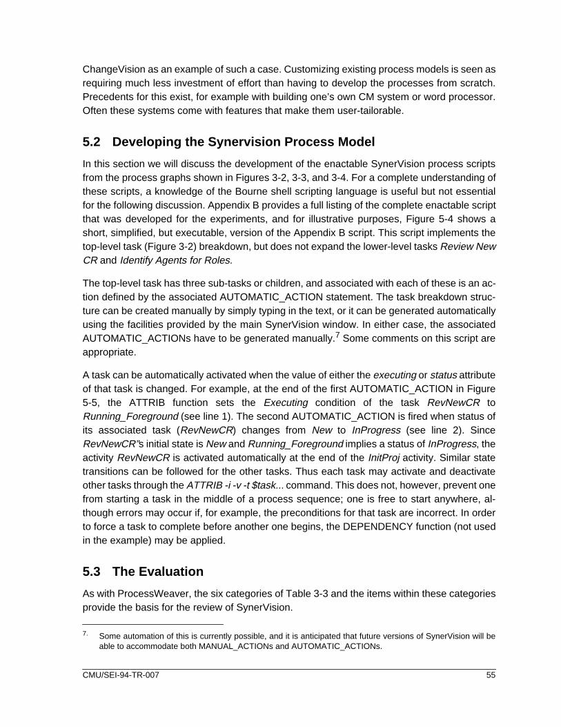
ChangeVision as an example of such a case. Customizing existing process models is seen asrequiring much less investment of effort than having to develop the processes from scratch.Precedents for this exist, for example with building one’s own CM system or word processor.Often these systems come with features that make them user-tailorable.
5.2 Developing the Synervision Process Model
In this section we will discuss the development of the enactable SynerVision process scriptsfrom the process graphs shown in Figures 3-2, 3-3, and 3-4. For a complete understanding ofthese scripts, a knowledge of the Bourne shell scripting language is useful but not essentialfor the following discussion. Appendix B provides a full listing of the complete enactable scriptthat was developed for the experiments, and for illustrative purposes, Figure 5-4 shows ashort, simplified, but executable, version of the Appendix B script. This script implements thetop-level task (Figure 3-2) breakdown, but does not expand the lower-level tasks Review NewCR and Identify Agents for Roles.
The top-level task has three sub-tasks or children, and associated with each of these is an ac-tion defined by the associated AUTOMATIC_ACTION statement. The task breakdown struc-ture can be created manually by simply typing in the text, or it can be generated automaticallyusing the facilities provided by the main SynerVision window. In either case, the associatedAUTOMATIC_ACTIONs have to be generated manually.7 Some comments on this script areappropriate.
A task can be automatically activated when the value of either the executing or status attributeof that task is changed. For example, at the end of the first AUTOMATIC_ACTION in Figure5-5, the ATTRIB function sets the Executing condition of the task RevNewCR toRunning_Foreground (see line 1). The second AUTOMATIC_ACTION is fired when status ofits associated task (RevNewCR) changes from New to InProgress (see line 2). SinceRevNewCR”s initial state is New and Running_Foreground implies a status of InProgress, theactivity RevNewCR is activated automatically at the end of the InitProj activity. Similar statetransitions can be followed for the other tasks. Thus each task may activate and deactivateother tasks through the ATTRIB -i -v -t $task... command. This does not, however, prevent onefrom starting a task in the middle of a process sequence; one is free to start anywhere, al-though errors may occur if, for example, the preconditions for that task are incorrect. In orderto force a task to complete before another one begins, the DEPENDENCY function (not usedin the example) may be applied.
5.3 The Evaluation
As with ProcessWeaver, the six categories of Table 3-3 and the items within these categoriesprovide the basis for the review of SynerVision.
7. Some automation of this is currently possible, and it is anticipated that future versions of SynerVision will beable to accommodate both MANUAL_ACTIONs and AUTOMATIC_ACTIONs.
CMU/SEI-94-TR-007 55

######################################################## identify task structure (main task and child tasks) ########################################################
TASK "Initiate Project"InitProj=$last_TASKID
CHILDREN_BEGIN
TASK "Review New CR" RevNewCR=$last_TASKID
TASK "Identify Agents For Roles" IdenAgForRl=$last_TASKID
TASK "Update Document" UpdateDoc=$last_TASKID
CHILDREN_END
################################################### Define AUTOMATIC_ACTIONs associated with tasks ###################################################
# Initialize variablesAUTOMATIC_ACTION -t $InitProj Status New Inprogress perform <<EOF ATTRIB -i -v manager "Paul" ATTRIB -i -v report "War and Peace" ATTRIB -i -v CR "Change Title" ATTRIB -i -v -t $RevNewCR "Executing=Running_Foreground" ### line 1 ###EOF
#send message to manager identifying document to be reviewedAUTOMATIC_ACTION -t $RevNewCR Status New Inprogress perform <<EOF ### line 2 ### CR=\‘GET_ATTRIB CR\‘ report=\‘GET_ATTRIB report\‘ manager=\‘GET_ATTRIB manager\‘ result=\‘svprompt -p "\$manager, please review change request \$CRfor document \$report and identify whether to accept or reject." -L -d "acceptreject"\‘# mark this task completed ATTRIB -i -v -t $RevNewCR "Status=Completed" if [ \$result = "accept" ]; then# start the next task
ATTRIB -i -v -t $IdenAgForRl "Executing=Running_Foreground" else# mark parent task as abandonded
ATTRIB -i -v -t $InitProj "Status=Abandoned" fiEOF
AUTOMATIC_ACTION -t $IdenAgForRl Status New Inprogress perform <<EOF svprompt -p "Now performing Identify Agents For Roles" ATTRIB -i -v -t $UpdateDoc "Executing=Running_Foreground" ATTRIB -i -v -t $IdenAgForRl "Status=Completed"EOF
AUTOMATIC_ACTION -t $UpdateDoc Status New Inprogress perform <<EOF svprompt -p "Now performing Update Document" ATTRIB -i -v -t $UpdateDoc "Status=Completed"EOF
Figure 5-5: Example of a Short SynerVision Script
56 CMU/SEI-94-TR-007

5.3.1 FunctionalityCategory 1 of Table 3-3 (functionality) is the largest category, since it is expanded to includeassessments of the capabilities defined in Tables 3-1 (Model-Development Capabilities) and3-2 (End-User Capabilities).
5.3.1.1 Model-Development Capabilities
Item 1a of Table 3-3 addresses “completeness of major functional areas for development, asidentified in Table 3-1”. This subsection thus reviews the items of Table 3-1.
Development: Scoping of variables: SynerVision allows variable values, defined anywherein the process hierarchy to be used anywhere else. However, visibility of the variable’s valuein the hierarchy is controlled using the ATTRIB function.
Development: Modeling hierarchies. SynerVision models task hierarchies through a tex-tual task breakdown structure. An example of such a structure is shown is Figure 5-1. Alsoprovided in this view are columns of user-customizable information on the tasks, such as timespent on the task. One can also illustrate this task structure graphically. However, the textualform provides a more compact and useful view of the task information than the graphicalform.
Development: Supporting model development. As discussed in Section 5.1.3, SynerVi-sion processes can be developed incrementally, from personal processes to group processesto formal process templates. All of this can be performed with little or no programming. In thislies a real strength. However, if one has to develop processes with any complexity, templatesare likely to require significant hand-coding. This requires a knowledge of the Bourne shelllanguage, and in this there are two drawbacks. First, development time can be lengthy anderror prone. As discussed in the following subsection, SynerVision currently has few debug-ging aids to support development. Second, it is likely to be difficult to communicate the result-ing process descriptions, using the templates, to the people who have either to use theprocesses, or to sign off on their acceptability. In this regard, a front-end graphical interfacefor process definition would be very helpful
Development: Creating a process library. One can build SynerVision process templatesfor library creation in two ways. In the first approach, the menu items in the window interface(see Figure 5-1) provide the functionality necessary to define logically simple processes. TheGenerate Template feature can then be used to automatically generate a permanent tem-plate script for that process. In the second approach, the template script is written by hand.Of course, an automatically generated script can subsequently be modified or expanded byhand.
Development: Supporting flexibility of task control. SynerVision allows the end user of aprocess to start intermediate tasks at any time. For example, one may wish to start writingcode, even although the formal code design has not yet officially been signed off. In thiscase, it is the user’s responsibility to make sure that the inputs to the task are correct. How-ever, SynerVision also provides the means to control task initiation, if necessary, through the
CMU/SEI-94-TR-007 57

DEPENDENCY function. In addition, a task attribute dependency-enforcement can be usedto specify whether this dependency is mandatory or can be overridden. Dependencies canalso be used to implement AND and XOR relationships between tasks. This flexibility of taskcontrol in SynerVision reflects a practical understanding of real-world user issues.
Development: Modeling standard programming constructs. Since the SynerVision tem-plate language is based on the Bourne shell scripting language, it has all the standard pro-gramming constructs that the shell contains, i.e., looping, conditionals, variable binding, etc.
Development: Performing parallel aggregated processes. For a discussion of this topic,see Performing parallel aggregated tasks in Section 4.3.1.1. SynerVision does not includeany explicit capability in this area. If one wishes to have identical processes performed in par-allel, one would have to program this into the script by hand, either by placing the commonprocess in a shell function which is called multiple times, or by duplicating the appropriatesegment of script for the common process.
Enactment: Assigning agents to roles . There is no explicit concept of “role” within Syner-Vision (other than the system administrator function) and thus there are no mechanisms forassigning agents to roles. Specific individuals are assigned read/write access to tasks anddocuments, depending on what their responsibilities are. One must explicitly program into atemplate the role mechanism, as is done in the experiment template (see the firstAUTOMATIC_ACTION in Appendix B).
Enactment: Supporting on-the-fly process modification . From practical considerations,there may be times when modification of a process that is currently being enacted is required.For example, a task performed late in a process may have to use a product different from thatspecified at the start of the process.8 In SynerVision, a process is guided by executing its pre-defined process script. The script cannot be changed during this execution and thus adaptingprocesses on-the-fly is not allowed. In the above example, this means that once the producthas been specified, it cannot be replaced by another, unless the possibility for this change hasbeen accounted for in the process script.
Enactment: Logging process data . For a discussion of this topic, see Logging process datain Section 4.3.1.1. SynerVision provides a feature called Process Adherence through whichreports of tasks actually performed can be generated. Additional data logging capability couldbe incorporated into a SynerVision script by saving information about tasks performed to afile. In theory, process roll-back could be implemented if appropriate process and productdata were logged. However, considerable thought would have to be given to its implementa-tion, particularly with respect tracking back through product versions — and SynerVisiondoes not provide any explicit capability to manage product versions. (See Managing Objectsbelow.)
8. However, if such modifications are allowed, they must be very carefully planned, or there could be serious sideeffects on the execution of the rest of the process.
58 CMU/SEI-94-TR-007

Resource: Invoking tools. Tools can be invoked in the template language through Bourneshell calls. This approach provides the simple ability to start and stop a tool, and was used inthe experiment (see Appendix B). HP’s Broadcast Message Server can be used to providegreater encapsulation functionality, but is not used here.
Resource: Managing Objects . For a discussion of this topic, see Managing Objects in Sec-tion 4.3.1.1. SynerVision process scripts are based on the Bourne Shell language and assuch have full access to all the Shell’s commands, including the SCCS version managementfunctions. There is, however, no explicit support for version control at the process manage-ment level.
Communication: Modeling communication between agents. Communications can beperformed in several ways:
• Tasks can be assigned from one person to another using the AccessAttributes window (Figure 5-2). Such assigned tasks appear in the receiversTask In-Box (Figure 5-3). Tasks assigned automatically (using the ATTRIBfunction in a process template) can also appear in the Task In-Box window.
• Communications between human agents or from the machine to a humanagent is supported inside scripts using the svprompt function. svpromptgenerates a customized dialog box that provides optionally for textualmessages, a text input field, and buttons.
• Communications can also be established through a connection toSoftBench’s Broadcast Message Server. Since this is not an explicit part ofSynerVision’s functionality, it is not used here.
Communication: Modeling automatic actions. If a task needs to initiate an automaticaction, or a sequence of actions,(i.e., actions without human intervention), the functionAUTOMATIC_ACTION is used. This was discussed in Section 5.2
Debugging: Syntax checking . SynerVision provides error information when a model isinstantiated and also at run-time. Since the template language is an extension of the Bourneshell, one can interactively debug expressions or redirect values of variables.
Debugging: Tracing process dynamics. Tracing of the real-time status of tasks can be per-formed by viewing the status column of the SynerVision Main window (see Figure 5-1). As aprocess evolves the status of tasks change and provide a limited indication of what is hap-pening. During the execution of a process, this feature also allows participants in the processto view task status. However, this trace feature is fairly limited as an aid for debugging.
Debugging: Logging process data. Selected process data can be logged to a file duringprocess execution through manually inserted statements in the process script.
Debugging: Reachability, deadlock, querying, spying . SynerVision does not supportthese functions.
CMU/SEI-94-TR-007 59

5.3.1.2 End-User Functional Capabilities
Scheduling periodic work. The ability to automatically schedule periodic tasks such asweekly meetings can be very useful. However, SynerVision does not explicitly provide this ca-pability (at least not without writing some Bourne shell script). This is an example of wheresome built-in higher-level functionality could improve end-user effectiveness.
Collecting metric data. One of the advantages of adopting a PCE is its potential for gatheringaccurate and complete metric data automatically, thus relieving the end-user of a distastefulchore. SynerVision provides very effective support for the collection and review of time- andtask-related metric data. For example, it will track actual-to-estimated task times, and percent-age of tasks complete.
Supporting project management tasks . Project management is supported through the met-ric data described above. Thus a project manager can maintain current knowledge of task sta-tus and can generate customized reports providing information about the status of a project.
Supporting the individual user. The individual user is supported in a variety of features for:
• generating personal task metrics,
• associating notes with tasks for guidance on the task, or for journaling,
• specifying task dependencies, and
• automating tasks (e.g., for tool invocation).
Supporting group communications. Users are supported in a variety of features for:
• setting up and operating a shared project,
• communicating between project members, and
• providing metric information on project status.
5.3.2 Developer IssuesEase of learning . SynerVision is in a conceptually new class of software product, is quitecomplex, and has many features. The novice to SynerVision must understand such conceptsas tasks (their ownership, status, behavior, etc.), processes (task hierarchies and dependen-cies, construction of personal and group processes), communication (accessing information,communication between project member and event management), metrics specification andcapture, and process template construction (using the Bourne shell and its SynerVision exten-sions).
Of these items the most challenging (in this author’s estimation) is the manual development ofprocess templates. As previously mentioned, this requires, as a basis, a good working knowl-edge of the Bourne shell language. Significant use is made of the here feature of the languageand this, combined with the need to distinguish between variable binding at process instanti-ation time and process run-time, can be a considerable challenge for new users.
60 CMU/SEI-94-TR-007

However, the development of simple processes (i.e., those not requiring manual constructionof templates) for either personal use or group use is well supported and much easier to do. Itis likely that an organization investing in SynerVision would start with these processes, workup to template customization, and then go on to the development of hand-written process tem-plates. This incremental approach provides a safe way in which to gain the necessary experi-ence.
Ease of use. SynerVision can be used in several ways. First, individuals can develop processtemplates for personal task management. Second, limited-size process templates can be de-veloped to support group activities. Both of these functions can be handled without a detailedknowledge of the SynerVision template language. These templates can be generated auto-matically and can thus be quickly and informally prepared, tested, used, improved, or discard-ed without too much investment of time or resources. Greater thought has to be given whenstandard templates are developed for complex processes in which the greater power and ex-pressiveness of the template language has to be used. This is likely to require significant de-veloper training, investment in requirements definition, coding, testing, etc., and a broaderconsideration of the process adoption issues.
Effectiveness of support for development. The developer’s view is accessed through theSynerVision main window (Figure 5-1) and is supported by the SoftEdit editor. The SynerVi-sion main window contains all of the capability to develop processes and automatically definetheir templates. Pull-down menus are used to select supporting functionalities, such as whohas access to tasks (Figure 5-2). Through the Task item in the menu-bar (Figure 5-1), one canselect options to create sub-tasks in the task hierarchy, to instantiate a process from a tem-plate file, or to generate a new template from a defined task hierarchy. This approach is effec-tive for developing process templates but could be enhanced in two ways. First, a moreeffective means for testing and debugging process models is needed (Section 5.3.1.2), andsecond, a process-oriented graphical front end would help define the model and communicateits nature to affected individuals.
Quality of on-line help. SynerVision has an extensive and excellent on-line help capabilitywith hypertext support. The path taken through the current hypertext sequence of selectionsis provided above the current help page. This prevents the user from becoming lost. The majorelements of the SynerVision help feature are the Step-by-Step Instructions and the GuidedTour. Also provided is an on-line Information OverView of ChangeVision. As an example ofthe Help features, Step-by-Step Instructions include the topics:
• Basics of Using SynerVision
• Creating and Manipulating tasks
• Setting Task Attributes
• Annotating a Task with Process Guidance Notes
• Viewing Tasks the Way you Prefer
• Project Metrics and Reports
CMU/SEI-94-TR-007 61

• Creating and Manipulating Manual Task Actions
• Using Shared Projects and Tasks
• Creating and Manipulating Process Templates
However, this on-line help does not cover programming in the SynerVision template language,a feature that could be very useful.
Error handling. SynerVision provides both instantiation and run-time error messages. Instan-tiation error messages provide some insights to problems, but do not, for example, identifytemplate line numbers where errors have occurred. The run-time error messages usually pro-vide insightful information. In developing and running the process models, no system crashesoccurred.
5.3.3 End-User IssuesEase of Learning . There are two main classes of end-user and each has different learningissues. The first class of end user will develop personal or group processes for its own imme-diate use through the automated generation of process templates. While some learning is re-quired, a major investment in time is not, since a high percentage of a process script isgenerated by the machine with appropriate end-user guidance. With this class of end-user,process adoption is not a primary issue since, by developing their own processes, such usersare internally motivated to apply them. The second class of end user will only be expected touse pre-defined templates, and thus need not be closely involved with their technical develop-ment. Learning to use the templates should not be difficult, since the process guides the userthrough the sequence of tasks. However, these end users are more likely to have the auto-mated process imposed upon them and thus may show resistance to change. Learning forthem is thus less technically focused and more culturally focused.
Ease of use . Using the automated process is not, by itself, difficult since the user is guidedthrough the needed process steps. In fact, if not designed effectively from a behavioral per-spective, this ease of use may well make the user feel like a cog in a machine, with the poten-tial for reducing creativity to button pushing and form filling.
Clarity of presentation . The standard end-user windows provided by SynerVision are shownin Figures 5-2 and 5-3. These allow for the sending and receiving of task delegation informa-tion and are straightforward to understand. However, the task information which can be dis-played in the Task In-Box (Figure 5-3) is limited basically to the task name and who assignedit.
During execution of a complex process scenario, a large number of currently active tasks maybe displayed at any one terminal. The Task In-Box can be used to list these tasks so long asonly brief information on the tasks is required. However, if more complex instructions or deci-sion making is required, then the Task In-Box is insufficient. For such tasks, customizing thepresentation must be done and this is performed using the svprompt function. A typical display
62 CMU/SEI-94-TR-007

generated by this function is shown in Figure 5-4. The clarity of information presented by thesedisplays has more to do with the developer’s use of the interface and the process context inwhich the windows are displayed than it does with SynerVision’s underlying features.
However, the currently implemented svprompt function provides a less than adequate meansfor managing its windows. Many task windows, such as shown in Figure 5-4 may reside on theterminal simultaneously, taking up space or hiding each other. In addition, the designer of theprocess interface is not provided with any control over the placement of documents or tools,that may be associated with tasks, are displayed. Management of these various windows isan issue with which SynerVision has yet to deal.
5.3.4 PerformanceExecution time efficiency. SynerVision was run on a HP Apollo 9000 Series 700 workstationrunning under HP-UX. The slowest common procedure with a noticeable delay is the instan-tiation of a process from its template. A one-task template (with eight lines of code) took 5 sec-onds for instantiation from the template, while the experimental model defined in Appendix B(184 lines of code) took about 33 seconds. This primarily affects developers who are debug-ging models and thus are required to instantiate models often, but it can also affect end users,since a process has to be instantiated from its template before it is used. Run-times for exe-cuting the process model are usually of less importance, since instant responses are not re-quired. (For example, when one end user sends a message to another end user, thecommunication time is generally not critical.) As with ProcessWeaver, these times are approx-imate, as a regular watch was used. Variability in times, resulting from different loadings onthe machine, was not a problem with SynerVision since the machine was isolated from otherusers.
Space efficiency. With respect to space efficiency, SynerVision takes about 2.7Mb of mem-ory, while the files in the SynerVision ‘bin’ directory takes about 7.2Mb. The experimental mod-el (Appendix B) takes about 8Kb.
5.3.5 System InterfaceEase of tool integration . Invoking Unix tools in process templates was simple to do usingBourne shell constructs (see Appendix B). However, directing SynerVision output to the ap-propriate end-user terminals created some frustration. This is in part because higher-levelconstructs for directing output were not available in SynerVision; this functionality had to bebuilt up from the Bourne shell. This is one area where some simple extensions to the scriptinglanguage could be a real benefit to the process developer.
More complex integrations using SoftBench’s Broadcast Message Server were not attempted.
Portability . At the time of writing, SynerVision is available only on Hewlett Packard Apollocomputers. However, the product is planned for release on Sun workstations in the first quar-ter of 1994.
CMU/SEI-94-TR-007 63

Interface to the operating system . SynerVision process models are based on the Bourneshell language which is part of the Unix operating system. In addition, SynerVision uses theUnix file system to store the process models.
5.3.6 Off-Line User SupportSupport from customer representatives . Customers purchase an annual support contractfor phone-in question answering and document update. Customers can also purchase specificservices such as for the development of specialized process templates.
Clarity of documentation . The current documents which support SynerVision are:
1. Installing SynerVision and ChangeVision
2. Introduction to SynerVision: Models of Use [SynerVision 93a]
3. Developing SynerVision Processes [SynerVision 93b]
The first document was not used since it had little relevance to the technology behind Syner-Vision and in addition SynerVision was already installed on the HP platform. The second doc-ument provides a good explanation of the different use-models described throughout Section5 of this report. It was very helpful in understanding the philosophy that guided the develop-ment of SynerVision and as a practical hands-on guide for exploring models that did not re-quire template programming. The third document, which is required for templateprogramming, is considerably less helpful and needs revision to be effective. Its principalweakness is the assumption that its readership knows the Bourne shell language. A review ofthis language, emphasizing the features that are commonly required in SynerVision tem-plates, would be valuable. The document’s other main weaknesses are its weak organizationand lack of good illustrative examples (not just code fragments) to clarify the technical pointsit is making. It might have made more sense for the latter two documents to be organized asa user manual and a reference manual. A tutorial manual would also be of significant help.
Availability of hands-on training . Customer on-site training is currently offered. In addition,a one-day management overview course will be given that focuses on the development anduse of SynerVision-supported processes.
Availability of encoded process examples. Since it is an example of a conceptually newclass of product, SynerVision should provide some simple application examples. This wouldhelp support the successful transfer of the technology to early adopters. As a minimum, ex-amples of simple templates for personal processes and group processes could be very useful.In addition, template programs, manually developed using the Bourne shell constructs, wouldhelp more advanced users.
64 CMU/SEI-94-TR-007

6 End-User Role Plays
This section deals with feedback obtained from persons who performed the end-user roleplays. Two groups of three persons performed these role plays; one technology orientedgroup of three persons and one process-oriented group of three persons. Each group per-formed the document review scenario with both the SynerVision implementation and the Pro-cessWeaver implementation. It should be noted that the number of persons participating inthe role plays was small and further studies, which involve larger numbers of people, wouldbe worthwhile. However, the results of this investigation showed some interesting and con-sistent results. The script shown in Table E-1 was used to guide the role-plays and, on com-pletion of each role play, the participants filled in the questionnaire shown in Table E-2.Figures 6-1 through 6-3 below summarize the results of the end-user responses to this ques-tionnaire.
ProcessWeaver was run from a Sun 4 host, while SynerVision was run from an HP-9000host. In both cases, the client machines were either Sun 4 platforms or Macintoshes (usingMacX). Thus the hardware environment was quite heterogeneous.
Before discussing the results, some aspects of Figures 6-1 through 6-3 are first explained.Each statement in the questionnaire is associated with five boxes which allow for a range ofresponses from full disagreement to full agreement. The number of responses for each boxwas tallied and totals are shown in the figures. These totals range from zero to four. (Therewere never more than four out of the six responses in any one box.) The ‘Bias’ column at theright hand side reflects the degree to which opinion differed between those participants with aprocess background and those with a technology background. A positive bias indicated thatthe “technology” participants were more favorably inclined to agree with the statement thanthe “process” participants, while a negative bias reflects the reverse. The bias was calculatedsimply by assigning the box number (items 1 through 5 in Table E-2) to the responses in thatbox, summing these assignments for the “technology” responses and also for the “process”responses and then subtracting the “process” total from the “technology” total. For example ifthe “technology” responses were in the boxes marked with a 2, a 4, and 5 while the “process”responses were in the boxes marked with a 1, a 3, and a 3, then the bias would be (2+4+5)-(1+3+3) = +4. It should also be noted here that the statements were designed to focus on thecharacteristics of the products’ features and not on the process example implementations.However, this clean separation was not always possible. Hence some of the responses maybe colored by the way in which the end-user interfaces of these products were constructed.
6.1 User Interface
Examining the data in Figure 6-1, it appears that there is a slight tendency to agree with thestatements rather than disagree. If one considers the response range being from 1 (total dis-agreement with the statement) through 5 (total agreement), a neutral response is reflected bya 3. Averaging across all ProcessWeaver’s responses (across all statements and all partici-
CMU/SEI-94-TR-007 65

A. Experience with the scenario (ProcessWeaver)
1 The screen layouts were easy to understand.
2 The instructional text was well formatted.
3 The instructional text was easy to read.
4 The Agenda window was useful in displaying current tasks.
5 The use of icons was helpful in organizing the task elements.
6 The use of buttons was effective.
7 The amount of information in the windows was good.
8 Computer response times were good.
9 I found it easy to understand the operating mechanics of the system.
10 The guided task sequence was helpful in managing the process.
11 The task sequencing was logical.
12 I would enjoy working in an environment supported by ProcessWeaver.
B. Experience with the scenario (SynerVision)
1 The screen layouts were easy to understand.
2 The instructional text was well formatted.
3 The instructional text was easy to read.
4 The use of buttons was effective.
5 The amount of information in the windows was good.
6 Computer response times were good.
7 I found it easy to understand the operating mechanics of the system.
8 The guided task sequence was helpful in managing the process.
9 The task sequencing was logical.
10 I would enjoy working in an environment supported by SynerVision.
Disagree Agree Bias
+2
+3
+3
-2
+1
-1
-1
+1
+1
-4
+1
0
Disagree Agree
+6
+3
+4
+3
+2
Bias
+5
+6
+3
+2
+2
Figure 6-1: Summary of End-User Experiences
66 CMU/SEI-94-TR-007

ble
Given your brief experience with the process automation scenario, would you feel comfortaworking in a process-centered environment if:1) it were designed by you and only supported your personal tasks,
2) you had input to its design, and it were used within your project,
3) it were predefined, but modified (with your input) for usewithin your project,
4) you did not have input to its design?
Do you think that working within a process-centered environment isnecessarily:
5) too invasive,
6) too impersonal,
7) too controlling?
Uncom-fortable
Comfort-able
No Yes
Bias
-4
-3
-2
-1
+6
+3
+6
Bias
Figure 6-2: Summary of End-User Views on Adoption of Automated Process
Do you think that process automation, as exemplified in the experiment, could be effectivelyapplied to improve productivity and software quality? Consider such areas as:
1) office paper-routing (e.g., document updating, document sign-offs)
2) software quality (e.g., inspections, walk-throughs)
3) software development (e.g., edit/compile/test cycle, systems integ.)
4) communications (e.g., subcontractor mgmt.., intergroup coord.)
5) metrics collection and analysis
6) process improvement (process definition, process reuse, or adaption)
Appro-riate
Inappro-priate
-2
-4
-1
+3
+1
-3
Bias
Figure 6-3: Summary of End-User Views on Appropriate Applications
CMU/SEI-94-TR-007 67

pants) the mean response is 3.64. The corresponding mean response for SynerVision is3.21. The three categories in which ProcessWeaver’s had a noticeably higher rating thanSynerVision were:
• The screen layouts were easy to understand.
• The guided task sequence was helpful in managing the process.
• I would enjoy working is an environment supported by ProcessWeaver.
This result may, in part, be because ProcessWeaver manages all tasks (i.e., the Work Con-texts) as icons inside its Agenda window and thus provides mechanisms for organizing andcontrolling ones tasks at a symbolic level. The SynerVision interface lacked this level of ab-straction (see Clarity of presentation in Section 5.3.3).
It is interesting to note the technology/process bias in Figure 6-1. The bias column clearly in-dicates that the technology participants were more positively inclined to the interfaces (partic-ularly SynerVision’s) than the process participants. The one significant counterpoint to thisgeneral conclusion is the response to statement A12. Here, the process participants appearedto be more favorably inclined to working within the ProcessWeaver environment than the tech-nology people. The following is an itemized list of (paraphrased) comments from the partici-pants. The comments are italicized, followed by the author’s remarks (non-italicized)
• Little context is provided when tasks arrived — I may know what I have to do,but I am not be provided with adequate context. For example, when thetechnical writers rejected the role of editor, there is no opportunity for themto provide the reason(s) why. This is a design problem with the processmodel, not a problem with either product. However, the example does pointout the importance of providing human communication channels whendeveloping an automated environment.
• SynerVision window management was lacking functionality. When adocument is invoked in the scenario, the document is simply thrown on thescreen, and may cover up other ongoing work. An inelegant solution to thisproblem could be devised by implementing additional buttons to allowdocuments (and tools) to be opened. However, a built-in feature to supportthis functionality should be part of the product.
• Both products lack the capability to undo an erroneous action (such asclicking on the wrong button). This is a necessary capability for a real-worldapplications. A generalization of this is process roll-back (discussed inSection 2.3.2), also missing in both products.
• I really liked the idea of the Agenda window in ProcessWeaver, where onecould keep track of outstanding work in one place.
68 CMU/SEI-94-TR-007

• Training: Comments clearly indicated a need for training in understanding theprocess. With the role play, little training was supplied. In a real-world setting,setting end-user expectations through training will be critical.
a. End-user training in the use of the process automation is essential.b. In practice, users need some form of tutorial on PCEs, either
classroom style or through access to self-help materials.c. In some cases in the scenario, it would be nice to have a bit better
description of what exactly to expect and when to expect it. In this wayI would know that the scenario was proceeding according to plan ornot.
• The foundations of process automation, as exhibited by both products isimpressive, but the technology has some way to go before it can beconsidered mature.
• When I shut off my terminal, do I lose all the tasks currently on the screen?This question was answered for the Macintoshes by exiting MacX (theMacintosh software which allows Macintoshes to act as terminals for Xwindow applications). This action disconnected the running SynerVisionmodel from the Macintosh and the connection could not be reestablished.For ProcessWeaver, tasks (i.e., Work Contexts) did persist when the sameprocedure was performed. On shutting down, and restarting SynerVision onthe HP-9000, the Synervision task structure and the task status wasrecovered, but the process seemed to lack information about the processstatus prior to the shutdown. Thus the process could still not be continued.On the other hand, ProcessWeaver appears to store this status informationsince shutting down and restarting ProcessWeaver did not appear to affectthe Work Contexts in the Agenda window.
6.2 Adoption Issues
Adoption issues are addressed here independently of either SynerVision or ProcessWeaver.Figure 6-2 provides the adoption-issue data from the end users. The responses to items 1through 4 clearly indicate a greater willingness to accept automation if one has control overthe process. Greatest acceptance is found when the processes are developed for personaluse, although there appears to be significant support for these processes in which the usershave input to the design. There was a consistently negative reaction to having an imposed ex-ternal process.
The bias factors in Figure 6-2 indicate that process-oriented individuals were less concernedwith adoption issues than were the technology individuals. This trend is particularly noticeablewith statements 5 through 7 where the issues of invasiveness, impersonality, and control areexamined. However, the trends shown by both groups were similar. (Note that the sign rever-sal between items 1 through 4 and 5 through 7 reflects the manner in which the statementswere made and not a reversal of opinion.) Typical of the comments in this area are:
• I would like to see the wider scope of what is happening. This might behelped by providing workers visibility into the status of activities in the project,and by providing the ability to send explanatory or confirmational messages.
CMU/SEI-94-TR-007 69

• Whether I felt comfortable in an automated environment would depend onhow process-driven I was. Acceptance might also be easier if one were newto a project or if the project itself were new (i.e., there are no built-inexpectations) rather than if a unfamiliar process were imposed upon anexisting project.
• On working in a process in which the user does not have input:
a. I would be uncomfortable working in someone else’s process.b. If I do not have any input to the design of the process, there’s a
chance I could live with it, but if it does not match my reality, I wouldbe dissatisfied.
• Comments of the ‘too invasive’ issue:
a. It could be too invasive if it tells me how to accomplish work insteadof telling me what needs to be accomplished.
b. Unlike e-mail I cannot elect when to receive information.c. It’s too invasive only to the extent that windows get popped in front of
you while you are concentrating on something else. The second issueis one of metrics gathering coupled with personnel evaluations. If thisis not handled well (i.e., the ground rules are well established, wellknown and accepted), it could be a really big issue. Otherwise I don’tfeel a process-centered environment is too invasive.
• Comments on the ‘too impersonal’ issue:
a. It’s no more impersonal than with e-mail. As with anything else,process automation is not a substitute for communication betweenstaff.
b. Automated environments would likely reduce personal interactionwith other human beings.
• Comments on the ‘too controlling’ issue:
a. I find the elimination of process navigation concerns to be a relief. Ican have the files and tools I need when I need them. It allows me toconcentrate on the work, not the setup.
b. Where do I get a chance for input other than “yes-no”? The machinecontrols my destiny with no human on the other end (or so it seems).
c. The only way it would be too controlling is if the process-centeredenvironment restricted all of my efforts to exactly what the process isscripted for. As long as this is not the case, and the environment isproviding timely guidance, this is OK with me.
6.3 Application Issues
Contrary to the results in Section 6.2 where concerns were raised about adoption of processautomation technology, Figure 6-3 indicates that there was a fairly positive response to apply-ing the technology to particular areas. In this section, the Bias indicator did not show any con-sistent trends between the technology and process individuals. The three applications whereprocess automation was seen to be most suited were: office paper routing, metrics collectionand analysis, and process definition and improvement. The following are typical comments:
70 CMU/SEI-94-TR-007

• Office paper routing:
a. Somewhat helpful, particularly in getting sign-offs.b. Excellent application, particularly if the tool supports tracking.
• Software quality:
a. Too people-intensive, a PCE doesn’t add much.b. I think the quality of inspections would decrease without face-to-face
meetings.c. For coordinating inspections, walk-throughs and for follow-up action
items, this would be good.• Software development:
a. Good for the individual.b. Good for automating a tasks that are (almost) always followed in the
same sequence.c. If it is supported by automated metrics collection, such as time spent
in each phase.• Communications:
a. Yes — if it makes sure everybody gets appropriate mail and info.b. Only appropriate if everyone has PCE support.c. PCEs should make communication as easy as with e-mail.d. A great way to ensure some form of recorded communications.
• Metrics collection and analysis:
a. Definitely could make these activities easier.b. Must watch out for gathering too much, or irrelevant information.
• Process improvement:
a. I think it would be a BIG mistake to encode process this way for adevelopment group.
b. Looks like a winner for assisting activities in process improvement.c. Good for process definition. However, need for a process asset
library.As can be seen from the results above, there were clear differences of opinion, ranging fromenthusiasm to concern, as to the effectiveness of applying automation to software develop-ment process. There was a slight but noticeable and fairly consistent divergence of opinionbetween those with a technology background and those with a process background. As mightbe expected, the technology-oriented participants viewed process automation with greater de-gree of scepticism. Since involving technical personnel will be central to successful imple-menting process automation, it is important to identify and deal with the issues technology-oriented individuals raise.
CMU/SEI-94-TR-007 71

72 CMU/SEI-94-TR-007

7 A Comparison of ProcessWeaver and Synervision
The objective of the experiments conducted with SynerVision and ProcessWeaver is to ex-plore an emerging technology using these products as examples. Both of these process-cen-tered frameworks have powerful mechanisms for enacting process and both, as members ofa new class of software, have their weaknesses. In any case, the successful application of ei-ther PCF (or other PCF as listed in Appendix A) is likely to depend as much on organizationaland human factors as on the product selected. Such issues as having an effectively definedprocess, good developer and end-user training, and sensitivity to technology adoption issueswill be at least as important for success as the chosen PCF.
ProcessWeaver and SynerVision have many similar capabilities, but implement these capa-bilities in different ways. Currently, both SynerVision and ProcessWeaver do not differentiatebetween the process developer and end user — each PCF provides the same functionality toboth groups. This allows end-users to implement their own personal processes or define pro-cesses for local project support, as well as allowing for the development of more ambitiousprocesses. However, there may be a need, particularly with large processes, to distinguish be-tween process-developer and end-user capabilities. Both PCFs implement reuse templates sothat a process can be instantiated and enacted from a library of previously defined processes.Both PCFs allow the end-user to enact subprocesses, independent of the parent process towhich they are associated. While tasks form the “building blocks” of processes in both PCFs,tasks can also be initiated, communicated, and worked on by end users in isolation from anyprocess.
It should be noted that neither of these PCFs is repository-based, and in that sense they em-phasize the control aspects of process rather than the data management aspects. Thus nei-ther has mechanisms for handling versions of products, or for controlling potential conflictsthat can arise from multiple agents modifying the same product. Data-centered products thathave emerged primarily from the configuration management community are also entering themarket place. Such products (e.g., CaseWare) do provide a repository and also allow one todefine and enact the processes that focus on a product’s evolution. However, these CM prod-ucts have narrower process modeling capabilities. Integration of PCFs with configuration man-agement products is probably needed, but since CM and PCF products may have differentnotions of “process,” care is probably required in this effort. It should also be pointed out thatneither ProcessWeaver nor SynerVision support some of the groupware concepts such as si-multaneous, remote collaboration on work, for example, in editing a document.
There are also some noticeable differences between the two products. ProcessWeaver em-phasizes a graphical approach to process definition. This approach defines a process bygraphically specifying an activity hierarchy, each activity being supported by a lower-level Petrinet model. In SynerVision, processes are defined in a text-oriented manner using an activityhierarchy, which is supported by scripting that specifies task behaviors and dependencies.
CMU/SEI-94-TR-007 73

SynerVision integrates some end-user applications,9 while a design decision was made withProcessWeaver to focus strictly on process support,10 allowing for application extensions tobe added as required. The following topics highlight some of the similarities and differences inmore detail.
Developing process models. With both ProcessWeaver and SynerVision, simple processmodels can be developed without any knowledge of their textual scripting languages. Becauseof its built-in project management and metrics tools, SynerVision allows one to develop rea-sonably sophisticated models without knowledge of its textual language. Also, as discussedin Section 5.1, SynerVision’s design provides a smooth incremental learning curve from sup-porting simple personal tasks to managing of group tasks. However, when one needs to de-scribe processes that require the explicit writing of SynerVision scripts, the learning curvebecomes much steeper.
As stated above, ProcessWeaver does not provide built-in metrics and project functionalitiesthat SynerVision provides. Thus, to include such capability in ProcessWeaver, one may haveto start using ProcessWeaver’s scripting language at an earlier point than with SynerVision.However, because of the graphical nature of much of the ProcessWeaver model, the degreeto which the scripting language has to be used may not be significant. Through ProcessWeav-er’s graphical approach, both the activity hierarchy and the process models associated witheach activity are defined. This approach provides two advantages:
• model development is faster, and
• fewer syntactic and semantic errors are introduced.
SynerVision’s approach to model definition is textually oriented (see Figure 5-5). The activityhierarchy can be displayed graphically, but this is somewhat superfluous as the textual viewis quite adequate (see Figure 5-1). However, because of the textual approach, building Syn-erVision process models by hand requires a greater investment in learning the language andis more time consuming than with ProcessWeaver’s graphical approach. Productivity in con-structing SynerVision models could also be improved if SynerVision had a richer set of higher-level functions. During the construction of the experiment, it was found that time was spentdeveloping supporting functions from Bourne shell elements and it would have helped if thesehad been built in.
While the graphical process support provided by ProcessWeaver is very helpful in developingmodels, neither SynerVision nor ProcessWeaver supported by a true graphical process enact-ment language. A graphical process enactment language is desirable in order to communicateall the essential process elements to others who will either have to sign off on a process or
9. That is, it has characteristics of a process-centered environment (PCE) since it supports end-user capabilitiesfor metrics collection and project management.
10. That is, version 1.2 of ProcessWeaver is strictly a process-centered framework (PCF).
74 CMU/SEI-94-TR-007

who will have to live within it. In addition to defining the relationships between all the majorprocess elements, such a graphical language should be able to display tasks, artifacts usedby tasks, and the agents (or roles) who perform the tasks.
The software underlying both SynerVision and ProcessWeaver was found to be robust in thesense that no system crashes and no significant system bugs were encountered during devel-opment.
Templates, roles, and process instantiation . Both SynerVision and ProcessWeaver haveexplicit mechanisms to allow for the initiation of isolated tasks and for sending these tasks offto the persons responsible for their execution.
With respect to processes (that embed tasks) SynerVision and ProcessWeaver provide for thedevelopment of process templates that allow for the repeated use of defined processes. If onedevelops a process in SynerVision, there is an explicit step that must be taken to generate atemplate from an existing runable process. However, in ProcessWeaver, one develops mod-els as templates (which, in turn, may embed default Cooperative Procedure templates). In ei-ther case, an instance of the template is generated and executed at run-time.
Every Cooperative Procedure in ProcessWeaver provides a parameters box to the processdeveloper in which variables required for the execution of that process are placed. Later, atrun-time, ProcessWeaver presents the process executor with a procedure parameters box inwhich the variable instances are filled in. In SynerVision, the process developer must explicitlybuild such mechanisms into the model using the scripting language. This is an example ofwhere the process developer’s task could be simplified if higher level functionality were builtinto SynerVision.
A SynerVision process model is basically contained within one file. This was found to be veryuseful for electronically transmitting the model to a remote location when debugging supportwas needed. Because a ProcessWeaver model consists multiple files, such a procedure be-comes less convenient.
Process control. Process definition in ProcessWeaver is based on a Petri net formulation,and this has resulted in one overly restrictive characteristic. Before a task in a CooperativeProcedure can begin, all the upstream tasks must have been completed. In real situations, itmay be possible for someone to start a task before all the formal conditions for task initiationhave been met, and indeed this opportunistic behavior may result in greater productivity. Sec-tion 4.3.1.1 discussed a possible resolution of this problem.
SynerVision does not exhibit this modeling constraint. Unless explicitly specified to the con-trary, an agent responsible for performing a task can begin at any time. Clearly there will betasks that must not start prior to other tasks ending, but this can be specified in the model.
Accessing external tools and the external environment. SynerVision allows access to ex-ternal tools using the standard Unix mechanisms and can communicate with its external envi-ronment using the functionality provided by Hewlett Packard’s Broadcast Message Server.
CMU/SEI-94-TR-007 75

ProcessWeaver supports similar mechanisms for tool invocation and communication. Pro-cessWeaver and SynerVision both provide a convenient means for associating tools with toolclasses. Thus on different platforms or with different users, different tools within the sameclass may be invoked.
SynerVision provides project management and metrics capabilities that are seamlessly inte-grated into the product. Processes can be developed incorporating these tools without aknowledge of the SynerVision scripting language. In addition the metrics tools provide the ca-pability to gather metric data such as time spent on a task without any intervention on the partof the task owner.
ProcessWeaver provides project management support through integration to external tools,but this is not as integrated as SynerVision’s support. Two tools are currently supported byProcessWeaver are: MicroSoft Project for Windows and Project Management Workbench 3.1(under PC/DOS).
Debugging. ProcessWeaver provides a variety of tools to support debugging. These includesupport for consistency checking (e.g., between inputs and outputs of Cooperative proce-dures), syntax checking of scripts, interactive debugging for the Co-shell language, and pro-cess visualization (that allows one to view tokens as they move around the Petri net and tospy on variable values during this process). SynerVision does not currently support any de-bugging aids other than that provided by the interactive shell that comes with Unix.
Documentation and examples. Neither SynerVision nor ProcessWeaver currently provideadequate documentary support. SynerVision’s manual Introduction to SynerVision: Models ofUse [SynerVision 93a] provides an excellent grounding in those aspects of SynerVision thatdo not require one to program. However, the more advanced manual, Developing SynerVisionProcesses [SynerVision 93b], is less well organized, needs improved explanations of the con-cepts, and should contain a greater number of complete examples rather than code frag-ments. This manual tries to be both a reference manual and a tutorial, and these two focusesshould probably be separated. SynerVision has extensive on-line support that supports thedevelopment of processes that do not need manually-encoded scripts.
The ProcessWeaver manuals (User and Reference) have three significant weaknesses. First,the User Manual lacks a good explanation of how the high-level elements of ProcessWeaver(Methods, Cooperative Procedures and Work Contexts and their supporting information box-es) relate to each other. Second, the Reference Manual needs to provide expanded coverageof the concepts in event handling supported by illustrative examples. Third, the ReferenceManual should provide more background into the functions that support the manipulation ofthe files stored under ProcessWeaver’s Universal Storage Mechanism format. In this versionof ProcessWeaver (1.2) on-line help was not implemented.
Both SynerVision and ProcessWeaver lack a good library of illustrative and executable pro-cess examples.
76 CMU/SEI-94-TR-007
The end-user view. ProcessWeaver provides a means of easily customizing, within a limitedformat, the information that is sent, either from one person to another, or that is sent to a per-son as a result of an automatic action. This window is called a Work Context (see Figure 4-2)and allows for text boxes, document or tool icons, and control buttons to be displayed. Uponclicking on an icon, a window containing the document or tool is opened for use. This end-userwindow management in ProcessWeaver was found to be quite effective.
SynerVision provides three main types of window for displaying end-user information. First, aTask In-box (see Figure 5-3) is provided that simply lists a person’s assigned tasks along withthe names of the task assigners. The main purpose of this window is to allow the assignee toaccept, reject, or reassign a task. Second, customized windows can be developed that containboth textual information related to the task, and control buttons. However, neither the Task In-box nor the customized windows can display icons representing documents or tools. A sup-porting document or tool can, however, be opened as needed to support the task, and this isdone by writing a line or two of Bourne shell script. However, this approach is not very elegantand SynerVision could incorporate improved functionality for managing end-user windows,particularly with respect to the support of task-related documents and tools. Finally, the Notesfeature may be used to supply the end-user with guidance on the task at hand or to documenthow a task was accomplished.
In summary, each PCF has different strengths and weaknesses. There is no “best” product —it truly depends on one’s needs. For example, ProcessWeaver provides developer-friendlysupport for graphically-based model building, while SynerVision has effective built-in supportfor project management and automatic metrics gathering. SynerVision provides more exten-sive capability for the project with modest process enaction objectives (when one can buildmodels without having to resort to hand-coded shell scripting). On the other hand, the higher-level functionality for building and debugging process models may make ProcessWeaver amore attractive choice when large models are being considered. The choice of which productto use (including the others listed in Appendix A) has to be made based on the requirementsof the project for which the process enactment model is being built. Both reviewed productsshow significant insights into what is needed for effective process enactment, but the imple-mentation paths have gone in different directions. The technology has some way to go beforereaching maturity, and practical field experience will make it more robust and provide the ven-dors with greater application knowledge.
CMU/SEI-94-TR-007 77

78 CMU/SEI-94-TR-007

8 Adopting and Using Process Automation Technology
Because there is as yet little industry experience in automating large-scale software process-es, it is wise to proceed cautiously. The following three subsections discuss some conserva-tive guidelines to follow when adopting this technology as well as providing some practicalsteps to its implementation.
8.1 Process Automation and Process Maturity
Automated processes are more “brittle” than manual processes, i.e., they are less adaptableto unforeseen circumstances and they cannot be modified as easily on the fly. Thus an under-standing of one’s manually-driven process is a prerequisite to the success of process automa-tion. It can be argued that a CMM Level 1 organization should not use a process-centeredframework for critical processes if these processes are not already understood, stable, andwell-defined. While it is tempting to think that a process-centered framework can help move aorganization from Maturity Level 1 to Level 2, stable manual processes (an essential ingredi-ent of a level 2 organization) will significantly reduce the risk of implementing a PCF. There isalso a concern that a Level 1 organization will become too preoccupied with the PCF technol-ogy rather that focus on the main issue which is process improvement.
This is not to say that a Level 1 organization cannot use some of the functionality provided byPCFs (such as supporting individuals in product development) or experiment with them insmall-scale noncritical areas, but experience should be gained before process automation isimposed on critical parts of one’s product line. Application to small-scale, noncritical areas willprovide a means to learn and gain confidence about both the technology and the adoption is-sues.
8.2 Guidelines for Adopting Automated Process
Adopting any new technology is likely to meet with significant resistance. Because of its per-vasiveness and potentially impersonal nature, this is particularly true with process automation.As with any new technology, some of this resistance will simply result from the fact that peopleoften do not like to change from their comfortable routine to new and uncertain ways. Howev-er, some resistance will also come from reasons unique to process automation technology.Such reasons are related to the controlling nature of the technology and the automated col-lection of personal productivity metrics. Typical reactions to these changes will include:
• Now I don’t talk to people, I only communicate through my terminal.
• I don’t want management to know every move I make.
• I don’t want to be treated like a cog in a machine.
• I know these metrics are going to be used against me in my annualevaluation.
CMU/SEI-94-TR-007 79

Such comments reflect the natural fears of staff members, particularly if management isviewed as authoritarian. Some of the resistance reflects a general reluctance to any changewhich significantly affects how one does ones job. However, process automation imposes be-havioral changes that are unique to that technology. Most computer tools (for software devel-opment, project management, etc.) are passive in the sense that they respond to thecommands of, and perform actions to support, the human agent. Process automation is differ-ent in that it can request actions of the human. While the roles of the computer and human arenot entirely reversed, this puts the computer at the same status level as the human (since thehuman can still request the machine to perform actions too). This question of roles may bedifficult for many to take, and is a major reason why adoption issues for process automationtechnology are so critical.
If management wishes to succeed, then it has to create an environment of trust that can onlybe achieved through closely involving the people who will have to live within the system. WhileHenry Ford may have been able to impose his will on the men in his assembly line by increas-ing their wages, such a crude approach is unlikely to work in the software field [Womack 90,Yourdon 92]. More sensitive strategies have to be used. The following points provide someexperience-based guidelines which may be useful to address when considering the applica-tion of process automation technology. [Fletcher 93] discusses similar issues with referenceto CASE.
1. Resistance to change . Resistance should be expected. Overt resistance isto be encouraged otherwise it can easily become covert and undermining. Is-sues, such as those in the bulleted list above, should be aired and discussionencouraged. Out of such discussions, ideas and approaches may be found,which, as well as being excellent in their own right, will foster a feeling of “buy-in”. Some of the strategies suggested in the paragraphs below relate to resis-tance and its resolution.
2. Process ownership. The philosophy of pushing down responsibility to aslow an organizational level as possible should be adopted. Thus the groupresponsible for performing a process which is to be automated should helpdefine, and should feel that it has ownership of, that automated process. Thismay be done by encouraging close collaboration between the user group anda software engineering process group (SEPG). The SEPG should know howto elicit information on the current processes and identify the user-group’srequirements on its automated equivalent, by:
• knowing how to define process models,
• knowing how to implement and validate enactable models,
• understanding metrics collection and analysis issues, and
• having the necessary skills to address adoption/transition issues.
3. Training. Training (for example, on process definition/automation, metricscollection and analysis) and setting expectations (for example, no layoffsresulting from automation, non-attribution of metrics data etc.) are significantcontributors to the success of this adoption task.
80 CMU/SEI-94-TR-007
4. Process improvement . In the same way that a group operating a processshould feel ownership if it, the group should also have the responsibility forimproving it. Thus the group should be responsible for collecting andanalyzing its own process metrics, encouraging suggestions for enhancingthe process and for implementing changes. These changes should, of courseconform to the organizational standards (see Item 8 below).
5. Process metrics . Process metrics should be managed by the group andshould be non-attributable to individuals. With the automated metriccollection, access to confidential metric data should be controllable, thusassuring those involved that such data will not be used in employeeevaluations. Only non-attributable data is passed up the management chain.Person-specific metrics are used by the group only to improve the group’sprocess; group-averages may then be used to support the improvement ofhigher-level processes.
6. Organizational context. Project processes should be defined within thebroader context of the organization. Thus the organization has theresponsibility to develop process definition standards (e.g., type of processdefinition/enactment methodologies), process interface standards (to allowfor compatibility between project processes and higher level processes), anddata format standards (to allow for information consistency betweenprojects). However, broad organizational standards should only be imposedafter sufficient exploratory experience is gained with process automation atthe project level.
7. Process interfaces. Broad higher-level process models may be used toguide the organization of the lower-level processes and information flows.However, these higher-level processes should not specify the details of theindividual processes. Detailed process definition should be a bottom-up task(using the standards). The top-down model may be periodically revised as aresult of bottom-up integration of tasks. In this way the model is organic, beingneither completely top-down nor bottom-up. Constraints on the constructionof individual processes include:
• inputs and outputs (both artifacts and decisions), derived from the higherlevel,
• guidelines and standards on process definition, and
• data formats.
8. Transitioning strategies . To institute automated processes in an existingproject, real-time validation may be required before commitment to the newprocess is made. One approach to this is to run the old (perhaps manual)process in parallel, side-by-side with the new automated process, makingsure that the inputs to both are identical. Outputs are then compared for sometime to assure that they are identical. In cases where the old and newprocesses are not the same, the two processes can still be run side-by-sideuntil sufficient confidence is gained that the new process is providing correctoutput (parallel strategy). Another strategy is to incrementally insert smallcomponents of the automated process into the old process in such a way thatthe change-over to the new process occurs gradually (incremental strategy).
CMU/SEI-94-TR-007 81

9. Process reuse . Processes that have been successfully run by one projectcan be captured in a corporate repository for use or modification by others.This not only reduces the effort in implementing processes in subsequentprojects, but will support the drive to organizational consistency of processand encourage communication between projects.
10.Granularity of process control. The manner in which a process is bemodeled should depend on the application area. In general, processes closerto technical development should provide increasing degrees of support orguidance and decreasing degrees of imposed control. For example,developers are unlikely to accept a level of overt, external control in whichevery act in the edit/compile/test cycle is regulated. However, they may wishto support their activities by developing their own personal process scripts.On the other hand, persons managing change requests or document reviewactivities may be very happy to have the support of an externally definedprocess in order to lift some of the administrative burdens from theirshoulders.
8.3 Transitioning to a PCF
In order to install an organization-wide integrated software development environment (notnecessarily a PCF), significant planning must be done [Humphrey 89]. While Humphreysuggests a two-phase strategy, the following approach expands that suggested by him andhas three phases. The first phase is exploratory and allows for technical and adoptionexperience to be gained. This phase may be done by projects having the characteristics of anorganization at Maturity Levels 1 or 2.11 The second (strategic) phase involves planning fororganizational adoption and requires the organization to be at least a high maturity Level 2.The third phase covers actual implementation of process automation within projects asdirected in phase 2.
Phase 1: Exploration
This phase is very important in allowing an organization to assess the appropriateness ofprocess automation for its culture, prior to making significant investments. Thus implementingone or more pilot processes should be the first step. Before starting, it is probably wise to readabout technology change management. Little has yet been written explicitly about adoptingprocess automation, but many of the issues are the same as those in the adoption of othertechnologies. Excellent places to start are [Oaks 92, Humphrey 89, Fletcher 93, and Block 81].The paper by [Dart 94] illustrates how close the issues of adopting automated configurationmanagement are to that of adopting automated process. The following criteria are suggestedin selecting an appropriate process to be automated:
11. The Capability Maturity Model [Paulk 93a] associates maturity levels with organizational characteristics, notproject characteristics. However, nearly all of Level 2 practices within the CMM focus on project characteris-tics. It is in this sense that the term “a project showing Level 2 characteristics” is used. Of course, the term “aproject showing Level 3 characteristics” makes little sense.
82 CMU/SEI-94-TR-007

• the process is modest in size,
• the process is well understood and stable,
• the process is not on the critical production path of external products,
• the project, of which the process is a part, is not constantly putting out“brushfires”, and
• the users of the process are positively inclined to automation.
Phase 2: Strategic planning
Once confidence has been gained through the demonstration process(es), the knowledge andskills gained can be put to use in developing a strategy that will allow wider and consistent im-plementation throughout the organization. The following activities are suggested:
• Establish an automation focal point (an individual). This person was probablypart of the Phase 1 activities, could be part of a software engineering processgroup, and must have an understanding of issues related to technology,process and adoption. Communication is also an essential skill for thisindividual.
• Define application focuses for automation (i.e., individuals, projects leaders,upper management and corporate staff).
• Develop a high-level requirements statement for the automation project.Include requirements for:
• communication,
• metric data collection,
• management tools,
• development tools,
• data repositories,
• vendor support, and
• training.
• Establish a strategic plan for PCF for adoption and maintenance.
• Assess the most promising PCF.
• Establish a corporate process reuse repository.
• Develop a handbook for the adoption of automated process which covers thetechnical, adoption, training, and reuse issues.
Phase 3: Project implementation
With experience in hand from the demonstrations, and the organizational framework providedby Phase 2, implementation throughout the organization’s projects can begin. For this phase,the following activities are suggested:
• Establish an implementation group composed of experts in the automationtechnology and members of the affected project. If necessary trainindividuals in the PCF and in adoption techniques.
CMU/SEI-94-TR-007 83
• Identify and evaluate project-based costs, benefits and risks associated withadoption of process automation.
• Develop project and application-specific process automation objectives andimplementation plans.
• Develop project and application-specific migration strategy based on thehandbook for the adoption of automated process.
• Define, develop and implement the process templates based on thehandbook for the adoption of automated process.
• Validate the effectiveness of the process by involving future users insimulated process role-plays (see Section 6)
• Provide training and hands-on experience for all affected parties.
• Track the progress of the automation project (getting feedback from users),document lessons learned, and improve the process model.
It may be helpful to expand on the activity of defining a project’s migration path by suggestingone possible scenario. This scenario assumes that Phases 1 and 2 have been completed andthat Phase 3 (project implementation) is starting. As mentioned above, a project showingLevel 1 characteristics will not have the process maturity to effectively use a PCF in the broadsense. A project with level 2 characteristics is therefore chosen to pilot the installation. At thispoint, the manually-defined process is chosen and adapted for automation using theorganization’s standards. It is then tested off-line through simulation. Critical project membersare closely involved in these activities. The functional elements supported by the PCF mayinclude development tools such as compilers, debuggers, etc., or management tools such asfor project planning and cost estimating. At this point a transition strategy must be planned andimplemented, and could, for example, use either the parallel or incremental approachdiscussed earlier (see Item 8 in Section 8.2). Transitioning the automated process into theproject also requires that the project members be trained in how to work and feel comfortablewith the automated process.
When sufficient confidence has been reached with the first project, other projects transition tothe use of the PCF, perhaps while concurrently achieving Maturity Level 2 characteristics. Inadopting the PCF, these latter projects will have to conform to the data standards set up forthe repository. This not only allows projects to communicate, but also sets the stage for theorganization to reach maturity Level 3. At Level 3, a major focus is on organizationalconsistency of process. Thus each project's process will be tailored to reflect theorganization's standard process. The process, as defined for each project, will be developedusing standard process modeling tools and stored within the organization's repository underCM control. Also, in moving towards Level 3, the organization will support access toolsallowing upper management to query the repository. This is possible since data across theorganization is now stored in a consistent manner.
The functionality provided by the PCF will need to accommodate changes in the process asprocess improvement takes place. Increasing complexity is to be expected as newrequirements, greater process complexity, and product variety are imposed. Significant
84 CMU/SEI-94-TR-007

modification of the process program is also likely since mistakes will be made as experienceis gained. If the process model is not resilient and flexible, it is likely that continued modificationof the associated software will overstress the original concept. This problem of processevolution and maintenance affects not only the process template design, but also challengesthe underlying mechanisms provided by the process programming language.
CMU/SEI-94-TR-007 85

86 CMU/SEI-94-TR-007

9 Summary and Conclusions
As software systems have grown in size and complexity, the ability to predictably managethem with respect to cost, quality, and on-time delivery has declined. This has led to an aware-ness of the importance of well understood software process as an essential ingredient in soft-ware development [Humphrey 89]. However, managing all the elements of software processrequires a significant investment in time and resources, and this may discourage organizationsotherwise favorably inclined to process improvement. Fortunately elements of many process-related tasks can be automated, providing support for both developers and managers in theirday-to-day efforts. Approached in the right manner, automation of the process has the abilityto bring improvements in both quality and productivity.
Automation can support process activities in many ways. Some of the important ones are:
• It assures that the development process is actually followed and can providea “paper trail” of the sequence of activities performed.
• It allows developers to communicate with each other and coordinate taskswith less effort.
• It can support project oversight by providing project and upper managementwith the current status of development activities.
• It can automatically link to project management tools, thus making updatesto project plans much simpler.
• It can reduce the chance of many process-related errors occurring bytransferring process control to the enacted model.
• It can support the automatic collection of metric data, thus eliminating thetime consuming and error prone tasks of manual collection.
• It can automatically provide input to a corporate repository to support processimprovement and project estimation.
• Through automation, many menial tasks can be removed from humaninvolvement.
• Process automation can provide a setting in which the developer has easyand context-dependent access to the tools he/she needs to perform thetasks.
• Finally, it can contribute to process reuse since a defined and validatedmodel can be captured in a process database.
It should be noted that there are also some potential pitfalls to using this technology. Most im-portantly, a process-centered environment cannot be viewed as simply a CASE tool to be im-posed on a developer. Process automation involves at least the whole project and perhapsthe broader organization. Any process-centered framework will impose ways of doing thingsthat may differ significantly from past experience. If not approached correctly, users of such aPCF could easily subvert it. A second issue is that of working within a defined process. It isunlikely that an automated process can be successfully implemented without the project hav-ing a well understood and stable manual process. This does not imply that the automated pro-
CMU/SEI-94-TR-007 87

cess need slavishly follow the manual process, but without an understanding of the basicproject tasks and information flows, etc., it is unlikely that the automated process will succeed.PCFs are fragile in the sense that they cannot easily change strategy in mid-stream if prob-lems arise. Humans have a remarkable ability to adapt to unforeseen circumstances; softwaresystems have still to learn this ability. Finally, PCFs are not a panacea, and indeed are still intheir infancy. Adopters cannot rely on the practical experience of others as there are, as yet,few examples of day-to-day industrial use.
Two PCFs, ProcessWeaver from Cap Gemini and SynerVision from Hewlett Packard, wereexamined in some depth in order to better understand the technology. It was found that theyprovided some functionality in common, but also differed in a significant number of ways.Characteristics in common include the ability to generate process templates thus allowing forprocess reuse, the ability to support personal task management in addition to implementingpredefined task sequences (i.e., processes), the ability to develop simple processes withouthaving to know either PCF’s scripting language, and an interface that serves the needs of boththe developer and end-user. This latter feature allows end-users to develop simple processesfor themselves or group use.
Differences between these PCFs include the following. ProcessWeaver’s approach to devel-oping models is primarily graphical. A process is defined at a high level through an activity hi-erarchy, each activity being supported by an associated process diagram These processdiagrams are defined using a Petri net notation. This graphical approach allows for a rapid pro-cess development and helps reduce the likelihood of errors. SynerVision essentially uses atextual approach to defining the process. An activity hierarchy is defined textually (although agraphical representation of this is available), and each of the activities has actions that are per-formed to satisfy it. Other information, such as dependencies between activities, may form partof the activity definition. ProcessWeaver’s Petri net approach is less flexible in that one mustcomplete all upstream tasks to the current task before it can begin. With SynerVision one canbegin a task any time providing that the necessary inputs are available and there are no ex-plicit constraints imposed by the process model.
SynerVision provides an effective suite of tools for automatically capturing different metric dataand for performing simple project management functions. These two features support eachother since both rely on the same types of data. On the other hand, the version of Process-Weaver which was evaluated (V1.2) provides links to connect to project management tools butdoes not provide this functionality directly. ProcessWeaver’s lack of support for process met-rics is seen as a weakness since there is such a close relationship between process automa-tion and the collection of process metrics. ProcessWeaver does, however, provide usefulfeatures for debugging process models, from consistency checking to simulation. To date Syn-erVision provides little support for debugging. Information windows, that provide the end userwith task-dependent messages for guidance and control buttons for decision making, are usedby both SynerVision and ProcessWeaver. ProcessWeaver has the added capability of dis-
88 CMU/SEI-94-TR-007

playing icons in these windows. These icons can represent documents or tools and can beopened to display the document (in, for example, a word processor) or tool, and provide a veryeffective means for managing tasks.
The documentation of both ProcessWeaver and SynerVision could be improved. One of Syn-erVision’s manuals provides a good explanation of the product if one is only going to generateprocesses without invoking the scripting language. However, the manual that describes thescripting language needs to be clarified and reorganized. ProcessWeaver’s documentationprovides a good explanation of the product’s major elements but fails to adequately explainhow these elements fit together. ProcessWeaver’s manual could also provide expanded cov-erage of the product’s lower level features. Both products could be significantly improved ifthey were supported by a wider set of executable examples and simple application cases (sim-ilar to the one developed in this report).
In conclusion ProcessWeaver and SynerVision both had the functionality to construct the ex-perimental model described earlier, and provided robust environments in which to build andenact the models. There were frustrations during model construction and debugging, andthese resulted from:
• inexperience at using the methodologies,
• product features that reflect early technology,
• less than adequate documentation, and
• lack of good illustrative and executable examples.
Unlike coding tools whose users typically have a sophisticated programming background,PCFs will have a less technical, and more process-oriented set of users. Both SynerVision andProcessWeaver have features that indeed support nontechnical users, but the needs of theseusers could be more adequately addressed. The basic technical approach used by eitherproduct is believed to be solid and form a good foundation for process automation. The currentlimitations of these products (most likely reflected in other PCFs; see Appendix A) are to agreat extent a consequence of the newness of this technology, and it is hoped that these lim-itations will be removed in time.
Process-centered frameworks provide the structure to support process automation. However,successful introduction of this technology imposes fundamental changes in the way softwareis developed. First, application of process automation is more likely to succeed if the organi-zation’s processes have already been defined and operated manually. This not only providesa basis for developing the automated equivalent of the process, but educates the organiza-tion’s staff on what it is like to work within a defined process. Second, imposing an automatedprocess requires a significant degree of trust between developers and management since itcan be perceived as being intrusive. Two major implications of this are:
CMU/SEI-94-TR-007 89

• in order to encourage feelings of ownership, affected project membersshould be closely involved in developing or adapting process to meet theirproject needs, and
• automated metrics collection is designed to assure that the data is used toimprove the process and not to evaluate an individual’s performance.
Third, to achieve success in process automation, a transition strategy is necessary. It is sug-gested that a three phase approach is used. The focus of the first phase is gaining experiencewith the technology and its adoption in small, noncritical processes.The second phase theninvolves strategic organizational planning, while the third phase involves implementationacross multiple projects. The strategic plan must have the visible and continued support of up-per management since the culture changes introduced by process automation will be signifi-cant and will likely be resisted.
The future of process automation has yet to be decided. Potentially it can bring dramatic im-provements in software productivity and quality, but questions remain to be answered. Is thetechnology sufficiently responsive and adaptable to human needs? Conversely will imple-menters be sufficiently aware of the critical human-factors issues? Will early failures at auto-mation prematurely give the field a bad reputation? Will resistance to working in an automatedprocess be a major impediment? Will process automation products be sufficiently flexible todescribe most process characteristics and sufficiently scalable to model “industrial-strength”projects? While answers to these questions will only be resolved in time, awareness of the is-sues and plans to deal with them will immeasurably improve the chances for success.
90 CMU/SEI-94-TR-007

References
[Block 81] Block, P. Flawless Consulting, San Diego: Pfeiffer and Co., 1981.
[Boone 91] Boone, G. “CASE and its Challenge for Change”, International Journal of SoftwareEngineering and Knowledge Engineering 1,2 (1991): 151-163.
[Brown 92] Brown, A. W.; Earl, A. N.; McDermid, J.A. Software Engineering Environments: Au-tomated Support for Software Engineers, New York: McGraw-Hill, 1992.
[Brown 93a] Brown, A. W. et al. “Experiences with a Federated Environment Testbed”, Pro-ceedings of the European Software Engineering Conference, Garmisch, Germany: SpringerVerlag, September 1993.
[Brown 93b] Brown, A.; Carney, D.; Oberndorf, P. & Zelkowitz; M.; eds. Reference Model forProject Support Environments: (CMU/SEI-93-TR-23). Pittsburgh, PA: Software EngineeringInstitute, Carnegie Mellon University, November 1993.
[Chen 83] Chen, P. P., ed. Entity-Relationship Approach to Information Modeling and Analy-sis, Amsterdam: North Holland, 1983.
[Christie 93a] Christie, A.M. “Process-Centered Development Environments: An Explorationof Issues”. (CMU/SEI-93-TR-04). Pittsburgh, PA: Software Engineering Institute, CarnegieMellon University, June 1993.
[Christie93b] Christie, A.M. “A Graphical Process Definition Language and its Application to aMaintenance Project”. Information and Software Technology, 35, 6/7, (June/July) 1993: 364-374.
[Curtis 92] Curtis, B.; Kellner, M.; Over, J. “Process Modeling”, Communications of the ACM,35, 9, (September 1992): 75-90.
[Cusumano 91] Cusumano, M. A. Japan’s Software Factories, New York: Oxford UniversityPress, 1991.
[CaseWare] CaseWare/CM Integration. Technical note from CaseWare Inc.
[Dart 91] Dart, S. “Concepts in Configuration Management Systems”, Proceedings of the ThirdInternational Conference on Software Configuration Management, ACM Press, Trondheim,Norway, June, 1991.
[Dart 94] Dart, S. “Adopting an Automated Configuration Management Solution”, Sixth AnnualSoftware Technology Conference, Salt Lake City: Paper presented at STC Conference, April1994.
CMU/SEI-94-TR-007 91

[Derniame 92] Derniame, J.C. ed. “Software Process Technology”, Second European Work-shop, EWSPT, ‘92, Trondheim, Norway: Springer-Verlag, September 1992.
[Earl 93] Earl, A. “An Introduction to the Notations of ProcessMaker”, Mark V Systems, Encino,CA., 1993.
[Ett 91] Ett, W.H. “Enacting the Software Process”, Washington DC: STARS ‘91 Proceedings,December 1991.
[Feiler 88] Feiler, P.H., & Smeaton, R. The Project Management Experiment (CMU/SEI-88-TR-7, ADA197490), Pittsburgh, PA: Software Engineering Institute, Carnegie Mellon Univer-sity, July 1988.
[Feiler 92] Feiler, P.H.; & Humphrey, W.S. Software Process Development and Enactment,(CMU/SEI-92-TR-04, ADA258465). Pittsburgh, PA: Software Engineering Institute, CarnegieMellon University, September, 1992.
[Fletcher 93] Fletcher, T.; & Hunt, J. Software Engineering and CASE: Bridging the CulturalGap, New York: McGraw-Hill Cap Gemini America Series, 1993.
[Humphrey 89] Humphrey, W. S., “Managing the Software Process”, Reading, MA: Addison-Wesley, 1989.
[Kaiser 90] Kaiser, G.E.; Barghouti, N. S.; & Sokolski, M. H. “Preliminary Experience with Pro-cess Modeling in the Marvel Software Development Environment Kernel”, Proceedings of theTwenty-Third Annual Hawaii International Conference on Systems Science, Vol. 2. IEEEComputer Society Press1990.
[Kellner 89] Kellner, M. “Software Process Modeling: Value and Experience”, 1989 SEI Tech-nical Review, Pittsburgh, PA: Software Engineering Institute, Carnegie Mellon Universi-ty,1989.
[Kellner 90] Kellner; & M., Rombach, H. D. “Comparison of Software Process Descriptions”,Proceedings of the 6th International Software Process Workshop: Support for the SoftwareProcess, Hakodate, Japan: IEEE Computer Society Press, October 1990.
[Kellner 93a] Kellner, M.: & Gates, L. P. “Evolution of Software Process”, Proceedings of theInternational Workshop on the Evolution of Software Process, Quebec, Canada, January,1993.
[Kellner 93b] Kellner, M.; & Phillips, R. W. “State of the Practice in Process Technology”, Pro-ceedings of the 8th International Software Process Workshop, Wadern, Germany: IEEE Com-puter Society Press, March, 1993.
[Majkiewicz 94] Majkiewicz, J. “How Smart are Smart Documents”, SunExpert 5,3 (March1994): 46-54.
92 CMU/SEI-94-TR-007
[Mi] Mi, P.; & Scacchi, W. “Process Integration in CASE Environments”, IEEE Software 9,2(March 1992): 45-53.
[NIST 93] “Reference Model for Frameworks of Software Engineering Environments, NISTSpecial Publication 500-211, August, 1993.
[Oaks 92] Oaks, K. S., Smith, D., Morris, E. Guide to CASE Adoption, (CMU/SEI-92-TR-15),Pittsburgh, PA: Software Engineering Institute, Carnegie Mellon University, November 1992.
[Osterweil 87] Osterweil, L. “Software Processes are Software Too”, 9th International Confer-ence on Software Engineering, Monterey, California, IEEE Computer Society Press, 1987.
[Page-Jones 92] Page-Jones, M. “The CASE Manifesto”, CASE Outlook, January-February,1992: 33-42.
[Paulk 93a] Paulk, M. C., et. al. Capability Maturity Model for Software, Version 1.1,(CMU/SEI-93-TR-24, ADA263403), Pittsburgh, PA: Software Engineering Institute, CarnegieMellon University, February, 1993.
[Paulk 93b] Paulk, M. C.; et al. Key Practices of the Capability Maturity Model, Version 1.1,(CMU/SEI-93-TR-25, ADA 263432), Pittsburgh, PA: Software Engineering Institute, CarnegieMellon University, February, 1993.
[Peuschell 92] Peuschel, B. Schafer, W., Wolf, S. “A knowledge-based Software DevelopmentEnvironment Supporting Cooperative Work”, International Journal of Software Engineeringand Knowledge Engineering, 2,1, (1992): 79-106.
[ProcessWeaver 93] ProcessWeaver User’s Manual and Reference Manual, Version PW1.2.Grenoble, France: CapGemini Sogeti, 1992.
[Rader 93] Rader, J.; Morris, E.J.; & Brown, A.W. “An Investigation into the State of the Prac-tice of CASE Integration”, pp. 209-221. Proceedings of Software Engineering Environments,‘93, IEEE Computer Society, July 1993.
[Reisig 82] Reisig, W., Petri Nets, Heidelberg: Springer-Verlag, 1982.
[Sobell 89] Sobel, M. G. A Practical Guide to the Unix System, 2nd Edition, Redwood City, CA:Benjamin Cummings, 1989.
[Soley 92] Soley, R. M., ed. Object Management Architecture Guide, V2.0, Object Manage-ment Group, September 1992.
[STARS 92] STARS Joint Activity Group. A Compendium of Process Concepts For Practitio-ners - PCP Abstracts, Submitted to Electronic Systems Center, Hanscomb AFB, October 30,1992.
[SynerVision 93a] SynerVision. Introduction to SynerVision: Models of Use, Hewlett-Packarddocument B3261-90002, Draft May 5, 1993.
CMU/SEI-94-TR-007 93

[SynerVision 93b] SynerVision. Developing SynerVision Processes, Hewlett-Packard docu-ment B3261-90003.
[Weiderman 86] Weiderman, N. H.; et al. “A Methodology for Evaluating Environments”,pp199-207, Proceedings of the ACM SIGSOFT/SIGPLAN Software Engineering Symposiumon Practical Software Development Environments, Palo Alto, CA: ACM publication, December1986.
[Womack 90] Womack, J. P., Jones D. T., Roos, D. The Machine that Changed the World,New York,: Rawson Associates, 1990.
[Yourdon 92] Yourdon, E., “The Decline and Fall of the American Programmer”, EnglewoodCliffs, NJ: Prentice Hall, 1992.
94 CMU/SEI-94-TR-007

Appendix A Vendor Information on PCFsThe following is a list of products which support process automation for software developmentor business workflow. This list is not all-inclusive. Configuration management products suchas CaseWare and groupware products such as Lotus Notes are also making an impact in theprocess area. For a review of other products (with a focus on document management) [Majk-iewicz 94] should be consulted
Life*FlowCompany: Computer Resources International A/S14205 SE 36th St.Suite 100Bellevue, WA 98006Contact: John WilkersonPhone: 206-649-1134Platforms supported: Sun SPARC, IBM RS6000, HP9000, PC Windows (client mode).
Process EngineerCompany: LBMS, Inc.1040 North Kings HighwaySuite 724Cherry Hill, NJ 08034Contact: Joni FullerPhone: 609-482-2011Platforms supported: Networked PCs
ProcessWeaverCompany: Cap Gemini America1114 Ave. of the Americas29th floorNew York, NY 10036Contact: Larry ProctorPhone (US): 1-800-759-8255 (pin: 513-3640)Platforms supported: Unix platforms including HP, Dec, Sun SPARC, IBM RS6000. The Agen-da (client mode) also runs under MicroSoft Windows.
CMU/SEI-94-TR-007 95

ProcessWiseCompany: ICLProcessWise Portfolio CenterICL Waterside ParkCain RoadBracknell, Berkshire, RG12 1FAUnited KingdomContact: Jane BurnsPhone (UK): 44-0344-711795Platforms supported: ICL DRS6000, ICL Series 39, Sun, Bull DPX20, IBM RS6000
SynerVisionCompany: Hewlett-Packard CompanySoftware Engineering Systems Division3404 East Harmony St., MS 7Fort Collins, Colorado 80525Contact: Dave Pugmire, Process Program ManagerPhone: 303-229-3265Platforms supported: HP9000. Sun SPARC platforms should be supported by the time this re-port is released.
96 CMU/SEI-94-TR-007
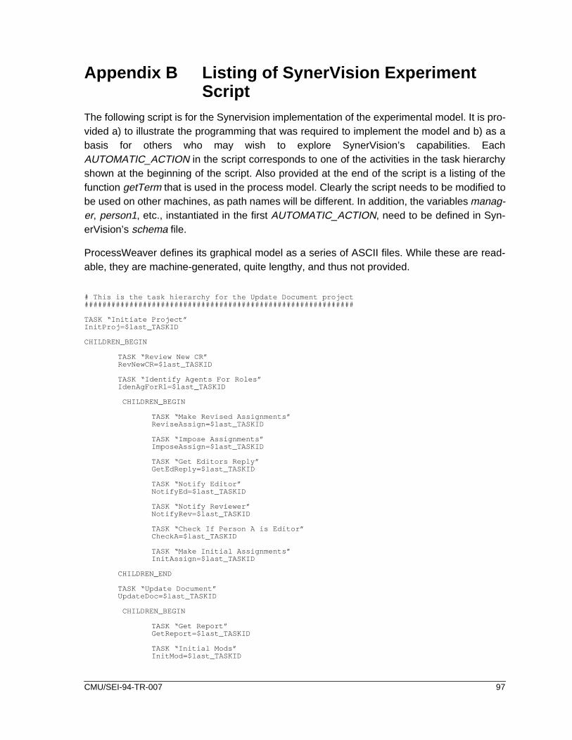
Appendix B Listing of SynerVision ExperimentScript
The following script is for the Synervision implementation of the experimental model. It is pro-vided a) to illustrate the programming that was required to implement the model and b) as abasis for others who may wish to explore SynerVision’s capabilities. EachAUTOMATIC_ACTION in the script corresponds to one of the activities in the task hierarchyshown at the beginning of the script. Also provided at the end of the script is a listing of thefunction getTerm that is used in the process model. Clearly the script needs to be modified tobe used on other machines, as path names will be different. In addition, the variables manag-er, person1, etc., instantiated in the first AUTOMATIC_ACTION, need to be defined in Syn-erVision’s schema file.
ProcessWeaver defines its graphical model as a series of ASCII files. While these are read-able, they are machine-generated, quite lengthy, and thus not provided.
# This is the task hierarchy for the Update Document project############################################################
TASK “Initiate Project”InitProj=$last_TASKID
CHILDREN_BEGIN
TASK “Review New CR”RevNewCR=$last_TASKID
TASK “Identify Agents For Roles”IdenAgForRl=$last_TASKID
CHILDREN_BEGIN
TASK “Make Revised Assignments”ReviseAssign=$last_TASKID
TASK “Impose Assignments”ImposeAssign=$last_TASKID
TASK “Get Editors Reply”GetEdReply=$last_TASKID
TASK “Notify Editor”NotifyEd=$last_TASKID
TASK “Notify Reviewer”NotifyRev=$last_TASKID
TASK “Check If Person A is Editor”CheckA=$last_TASKID
TASK “Make Initial Assignments”InitAssign=$last_TASKID
CHILDREN_END
TASK “Update Document”UpdateDoc=$last_TASKID
CHILDREN_BEGIN
TASK “Get Report”GetReport=$last_TASKID
TASK “Initial Mods”InitMod=$last_TASKID
CMU/SEI-94-TR-007 97

TASK “Modify Report”ModReport=$last_TASKID
TASK “Review Report”RevReport=$last_TASKID
TASK “Put Report”PutReport=$last_TASKID
CHILDREN_END
CHILDREN_END
# Each AUTOMATIC_ACTION below is associated with one of the tasks above#######################################################################
AUTOMATIC_ACTION -t $InitProj Status New Inprogress perform <<EOF# Initialize the variables for the project
ATTRIB -i -v manager “Paul”ATTRIB -i -v person1 “Leonard”ATTRIB -i -v person2 “Alan”ATTRIB -i -v report “TestReport”ATTRIB -i -v CR “CR_No_1”ATTRIB -i -v notes “ReviewNotes”ATTRIB -i -v inc 0ATTRIB -i -v -t $RevNewCR “Executing=Running_Foreground”
EOF
AUTOMATIC_ACTION -t $RevNewCR Status New Inprogress perform <<EOF# Send a message to the manager requesting him to decide on the acceptability of the# modification. If the modification is unacceptable, the project terminates here.
CR=\‘GET_ATTRIB CR\‘report=\‘GET_ATTRIB report\‘manager=\‘GET_ATTRIB manager\‘display=\‘getTerm \$manager\‘DISPLAY=\$displayexport DISPLAYcd /users/amc/SVdataget -e s.\$report>tempchmod a-w \$reportemacs \$CR &emacs \$report &result=\‘svprompt -p “\$manager, please review the acceptability of change request \$CR
per the document \$report then press either the Accept or Reject button” -L -d “AcceptReject”\‘ # mark this task completed
ATTRIB -i -v -t $RevNewCR “Status=Completed”if [ \$result = “Accept” ]; then
# start the next taskATTRIB -i -v -t $IdenAgForRl “Executing=Running_Foreground”
else # mark parent task as abandonded
ATTRIB -i -v -t $InitProj “Status=Abandoned”fidelta s.\$report>temp
EOF
AUTOMATIC_ACTION -t $IdenAgForRl Status New Inprogress perform <<EOF# This task is for continuity -- it has no action except to call to a lower-level task
ATTRIB -i -v -t $InitAssign “Executing=Running_Foreground”EOF
AUTOMATIC_ACTION -t $UpdateDoc Status New Inprogress perform <<EOF# This task is for continuity -- it has no action except to call to a lower-level task
ATTRIB -i -v -t $GetReport “Executing=Running_Foreground”EOF
AUTOMATIC_ACTION -t $InitAssign Status New Inprogress perform <<EOF# The manager makes an initial assignment of the proposed editor,and by default, also the# reviewer.
report=\‘GET_ATTRIB report\‘ manager=\‘GET_ATTRIB manager\‘ personA=\‘GET_ATTRIB person1\‘ personB=\‘GET_ATTRIB person2\‘ display=\‘getTerm \$manager\‘ DISPLAY=\$display assign=\‘svprompt -p “\$manager, please make an initial assignment of who
will edit the report \$report” -L -d “\$personA\$personB”\‘
if [ \$assign = \$personA ]; thenATTRIB -i -v -t $InitProj editor \$personA
98 CMU/SEI-94-TR-007

ATTRIB -i -v -t $InitProj reviewer \$personBelse
ATTRIB -i -v -t $InitProj editor \$personBATTRIB -i -v -t $InitProj reviewer \$personA
fiATTRIB -i -v -t $InitAssign “Status=Completed”ATTRIB -i -v -t $GetEdReply “Executing=Running_Foreground”
EOF
AUTOMATIC_ACTION -t $ReviseAssign Status New Inprogress perform <<EOF# As a result of the first person refusing the editor role, the second person is chosen to be# the editor.
personA=\‘GET_ATTRIB reviewer\‘personB=\‘GET_ATTRIB editor\‘ATTRIB -i -v -t $InitProj editor \$personAATTRIB -i -v -t $InitProj reviewer \$personBATTRIB -i -v -t $ReviseAssign “Status=Completed”ATTRIB -i -v -t $CheckA “Status=New”ATTRIB -i -v -t $GetEdReply “Status=New”ATTRIB -i -v -t $GetEdReply “Executing=Running_Foreground”
EOF
AUTOMATIC_ACTION -t $ImposeAssign Status New Inprogress perform <<EOF# As a result of the secon person refusing the editor role, the manager must decide who will be# the editor (and then by default, who will be reviewer).
manager=\‘GET_ATTRIB manager\‘personA=\‘GET_ATTRIB person1\‘personB=\‘GET_ATTRIB person2\‘display=\‘getTerm \$manager\‘DISPLAY=\$displayassign=\‘svprompt -p “\$manager, both staff members have refused the editing assignment.
Please assign either \$personA or \$personB to be editor” -L -d “\$personA\$personB”\‘
if [ \$assign = \$personA ]; thenATTRIB -i -v -t $InitProj editor \$personAATTRIB -i -v -t $InitProj reviewer \$personB
elseATTRIB -i -v -t $InitProj editor \$personBATTRIB -i -v -t $InitProj reviewer \$personA
fiATTRIB -i -v -t $NotifyEd “Executing=Running_Foreground”ATTRIB -i -v -t $NotifyRev “Executing=Running_Foreground”ATTRIB -i -v -t $ImposeAssign “Status=Completed”
EOF
AUTOMATIC_ACTION -t $NotifyEd Status New Inprogress perform <<EOF# The person selected to be editor is notified of the manager’s choice.
report=\‘GET_ATTRIB report\‘personA=\‘GET_ATTRIB editor\‘display=\‘getTerm \$personA\‘DISPLAY=\$displaysvprompt -p “\$personA, you have been selected to be editor for report \$report”ATTRIB -i -v -t $NotifyEd “Status=Completed”
EOF
AUTOMATIC_ACTION -t $NotifyRev Status New Inprogress perform <<EOF# The person selected to be reviewer is notified of the manager’s choice.
report=\‘GET_ATTRIB report\‘personB=\‘GET_ATTRIB reviewer\‘display=\‘getTerm \$personB\‘DISPLAY=\$displaysvprompt -p “\$personB, you have been selected to be reviewer for report \$report”ATTRIB -i -v -t $UpdateDoc “Executing=Running_Foreground”ATTRIB -i -v -t $NotifyRev “Status=Completed”ATTRIB -i -v -t $IdenAgForRl “Status=Completed”
EOF
AUTOMATIC_ACTION -t $CheckA Status New Inprogress perform <<EOF# Select path to next task depending on whether this is the first of second request for a# volunteer to be editor.
report=\‘GET_ATTRIB report\‘reviewer=\‘GET_ATTRIB reviewer\‘inc=\‘GET_ATTRIB inc\‘personA=\‘GET_ATTRIB editor\‘display=\‘getTerm \$personA\‘DISPLAY=\$displayif [ \$inc = 0 ]; then
ATTRIB -i -v -t $InitProj inc 1reviewer=\‘GET_ATTRIB reviewer\‘svprompt -p “I will check to see if \$reviewer will be editor”ATTRIB -i -v -t $ReviseAssign “Executing=Running_Foreground”
CMU/SEI-94-TR-007 99

elsemanager=\‘GET_ATTRIB manager\‘ reportA=\‘GET_ATTRIB report\‘ svprompt -p “\$manager will have to decide who will update \$report”ATTRIB -i -v -t $ImposeAssign “Executing=Running_Foreground”
fiATTRIB -i -v -t $CheckA “Status=Completed”
EOF
AUTOMATIC_ACTION -t $GetEdReply Status New Inprogress perform <<EOF# Send message asking if person will volunteer to be editor. Depending on the result, select# appropriate next task.
CR=\‘GET_ATTRIB CR\‘report=\‘GET_ATTRIB report\‘personA=\‘GET_ATTRIB editor\‘reportA=\‘GET_ATTRIB report\‘display=\‘getTerm \$personA\‘DISPLAY=\$displayreply=\‘svprompt -p “\$personA are you willing to act as editor for \$report
per the change request \$CR” -L -d “acceptreject”\‘
if [ \$reply = “accept” ]; thenATTRIB -i -v -t $NotifyRev “Executing=Running_Foreground”
else ATTRIB -i -v -t $CheckA “Executing=Running_Foreground”
fiATTRIB -i -v -t $GetEdReply “Status=Completed”
EOF
AUTOMATIC_ACTION -t $GetReport Status New Inprogress perform <<EOF# Retrieve report form repository.
report=\‘GET_ATTRIB report\‘CR=\‘GET_ATTRIB CR\‘cd /users/amc/SVdataget -e s.\$report>tempchmod a-w \$CRATTRIB -i -v -t $InitMod “Executing=Running_Foreground”ATTRIB -i -v -t $GetReport “Status=Completed”
EOF
AUTOMATIC_ACTION -t $InitMod Status New Inprogress perform <<EOF# Request the the editor updates the document as requested in the change request.
editor=\‘GET_ATTRIB editor\‘report=\‘GET_ATTRIB report\‘CR=\‘GET_ATTRIB CR\‘display=\‘getTerm \$editor\‘DISPLAY=\$displayexport DISPLAYcd /users/amc/SVdatachmod a+w \$reportemacs \$report &emacs \$CR &svprompt -p “\$editor, please update \$report, as
requested in the chnage request \$CR. When you are fininshed,press the OK button”
ATTRIB -i -v -t $RevReport “Executing=Running_Foreground”ATTRIB -i -v -t $InitMod “Status=Completed”
EOF
AUTOMATIC_ACTION -t $ModReport Status New Inprogress perform <<EOF# A a result of the document review, the document still needs revision. The editor is requested# to make these revisions.
editor=\‘GET_ATTRIB editor\‘report=\‘GET_ATTRIB report\‘CR=\‘GET_ATTRIB CR\‘ReviewNotes=\‘GET_ATTRIB notes\‘display=\‘getTerm \$editor\‘DISPLAY=\$displayexport DISPLAYcd /users/amc/SVdatachmod a+w \$reportemacs \$report &emacs \$CR &chmod a-w \$ReviewNotesemacs \$ReviewNotes &svprompt -p “\$editor, unfortunately your revisions to \$report did not pass review.
Please modify the document as indicated by the comments in \$ReviewNotes. When you are finished, press the OK button.”
ATTRIB -i -v -t $RevReport “Status=New”ATTRIB -i -v -t $RevReport “Executing=Running_Foreground”ATTRIB -i -v -t $ModReport “Status=Completed”
100 CMU/SEI-94-TR-007

EOF
AUTOMATIC_ACTION -t $RevReport Status New Inprogress perform <<EOF# The reviewer checks the revised document against the change request. This can result in the# document passing or the review or requiring further work.
reviewer=\‘GET_ATTRIB reviewer\‘report=\‘GET_ATTRIB report\‘CR=\‘GET_ATTRIB CR\‘ReviewNotes=\‘GET_ATTRIB notes\‘display=\‘getTerm \$reviewer\‘DISPLAY=\$displayexport DISPLAYcd /users/amc/SVdatachmod a-w \$reportemacs \$report &emacs \$CR &chmod a+w \$ReviewNotesemacs \$ReviewNotes &reply=\‘svprompt -p “\$reviewer, please review this updated version of \$report,
using the change request \$CR, and comments in \$ReviewNotes. Any additional comments should also go into \$ReviewNotes.” -L -d “DocOKNeedsFurtherWork”\‘
if [ \$reply = “DocOK” ]; then chmod a-w \$ReviewNotes ATTRIB -i -v -t $PutReport “Executing=Running_Foreground”
elseATTRIB -i -v -t $ModReport “Status=New”ATTRIB -i -v -t $ModReport “Executing=Running_Foreground”
fiATTRIB -i -v -t $RevReport “Status=Completed”
EOF
AUTOMATIC_ACTION -t $PutReport Status New Inprogress perform <<EOF# The updated document is saved in the repository and the manager is informed of completion of# the project
manager=\‘GET_ATTRIB manager\‘report=\‘GET_ATTRIB report\‘display=\‘getTerm \$manager\‘cd /users/amc/SVdatadelta s.\$report>tempDISPLAY=\$displaysvprompt -p “\$manager, the report \$report has been successfully updated”ATTRIB -i -v -t $UpdateDoc “Status=Completed”ATTRIB -i -v -t $InitProj “Status=Completed”
EOF
The following is a listing of the function getTerm used in the above script.
#Given a user’s name, return the display they use
user_name=$1
( grep $user_name | awk -F/t ‘{print $3}’ ) <<EOF
Proper Name Login Display-------------------------------Alan Christie amc bsPaul Zarella pfz ncday:0.0Leonard Green lsg ncday:0.0
EOF
CMU/SEI-94-TR-007 101

102 CMU/SEI-94-TR-007

Appendix C A Brief Overview of ProNetTo understand the process diagrams of Section 3, this section provides a brief guide to theProNet notation. ProNet diagrams are based on a modified Entity-Relation model [Chen], inwhich the entities fall into one of eight classes. The following list defines the entity classesused in an enactable model, and shows the symbols associated with each entity class12:
•Activities - are central elements of the process model and both consumeartifacts or conditions (as inputs) and generate artifacts or conditions (asoutputs). Activities may be atomic or may be composed of subprocesses.
•Artifacts 13- can either be required to support an activity or be producedby an activity.
•Conditions - can either be required to initiate an activity or result from anactivity and take the values TRUE or FALSE.
•Agents - are specific entities that perform activities. Humans or non-human entities capable of performing activities are considered to beagents.
•Composites - are boolean combinations of conditions, artifacts, agents,etc.
•Stores - allow for persistence of instantiated entities. Artifacts, conditionvalues, and even agents can be deposited in or retrieved from stores.
Relationships link the entities to the activities. Thus relationships are of the form:
{artifact} is entrance artifact for {activity}
{activity} has exit artifact {artifact}
{agent} is entrance agent for {activity}
Artifacts, conditions, agents and stores may have unknown values at the time the process isdefined. For these entities, a “$” sign is placed in front of the entity’s name. These entities willneed to have their value instantiated at execution time14.
In the process diagrams, these relationships allow the reader to identify the class of entity thatis linked to the activity. Also, if the relationship “artifact_1 is entrance artifact for activity_1”holds, so does the inverse relationship “activity_1 has entrance artifact artifact_1”. A black dot
12. The set of graphical symbols defined here is expanded over the set used in [Christie 93a].
13. The term “product” , which was was used in the initial version of ProNet, has been relaced by the term “artifact.”
14. In the initial version of ProNet [Christie 93a, Christie 93b] the convention of prefixing entities with a “$” was notused. In that initial version, the entity classes “agent” and “role” were defined separately. Placing a “$” sign infront of an agent’s name implies that the agent is unspecified prior to run-time. This is equivalent to the previ-ous notion of a role, and hence there is no longer a need for the “role” class.
CMU/SEI-94-TR-007 103

is placed next to the entity at the end of the relationship. For example in the relationship “ABCis entrance artifact for XYZ”, the dot would appear in the graphical relationship close to the boxsurrounding the activity XYZ.
C.1 Hierarchical Decomposition
Activities can be processes in their own right. Thus an activity at one level can be expandedinto a process diagram at a lower level. For consistency, inputs to and outputs from an activitymust propagate through to the lower-level process that it represents. Thus consistency of in-formation at the interface between levels is maintained.
To illustrate these points, examine Figures 3-2 and 3-3. The activity Identify Agents for Rolesin Figure 3-2 has its elements defined by the process diagram in Figure 3-3. As can be seen,inputs to the process diagram are attached to the left-hand edge of the diagram, while outputsfrom that process are attached to the right-hand edge of the diagram.
C.2 Composites, Versions, and Stores
An important concept in the basic notation in the composite class. Composites allow booleancombinations of entities to be logically related, either as input to an activity or as the outputfrom an activity. There are four instances of the composite class: CA, CO, DA, and DO, where“C” stands for “convergent”, “D” stands for “divergent”, “A” stands for “AND”, and “O” standsfor “OR”. Since convergent composites are always implemented prior to an activity they arecalled “entrance composites”. Similarly, since divergent composites are always implementedafter an activity they are called “exit composites”.
Iteration is required when, for example, a artifact undergoes a series of revisions, each revi-sion being different from the last and thus requires looping around a sequence of processsteps. Consider a artifact (prod) that is initially created, at which time an incrementing variableis set to an initial value (create_prod | i=1). Each time the artifact in updated in the activityupdate_prod, the variable is also incremented (update prod| i++). Versions of artifacts aretagged with the variable i, and hence versions of the artifact are defined. Thus prod | i repre-sents the i’th version of the artifact. Nested loops can also be implemented using this notation.
Stores support collections of artifacts and conditions values, and thus allow for modeling ofpersistency of generated entities. Since we must be able to add these entities to or retrievethese entities from a store, we introduce two special activities. These do not generate arti-facts, conditions, etc., but add artifacts to and remove artifacts from a store. The activitytypes (put, get) are illustrated in Figure C-1 and are added on to the front of the activity nameas shown in the Figure C-1.
104 CMU/SEI-94-TR-007

C.3 An Example of a Simple ProNet Model
Figure C-2 illustrates a simple ProNet model fragment. A change request (CR) is initialized atwhich time the incrementing variable is set to an initial value (initialize CR | i=1). The outputfrom that activity is the first version of the change request (CR | 1). The composite (CO) ac-cepts either the first or subsequent versions of the change request as input to the activity re-view CR. Output from review CR can either be the condition CR OK or the artifact revisionrequest | i. Each time the change request is updated, the variable i is incremented (update CR| i++). Note that each activity is supported by an agent.
Adds artifact_X into store_A:
Retrieves artifact_X from store_A:
Figure C-1: Definition of Activities Associated Only with “Store” Entities
put_entity_X
get_entity_X
artifact_X
artifact_X
store_A
store_A
condition_Q
condition_Q
is entrance artifact for is exit store for
is exit condition for
is entrance store for is exit artifact for
is entrance condition for
CMU/SEI-94-TR-007 105

Figure C-2: Simple ProNet Change Request Model
reviewCR
$CR1 | 1 $CR2 | i
$revisionRequest | i
CO
DO
CA
CR OK
$developer
$reviewer
has entrance role
has entrance agent
has exit artifact has exit artifact
has entrance artifact
has entrance artifact
has entrance composite
has entrance agent
has exit composite
has exit artifact
has exit condition
has entrance artifact
has entrance composite
has entrance artifact
. . . .
updateCR | i++initializeCR | i=1. . . .
106 CMU/SEI-94-TR-007

Appendix D Terminology and ConceptsThis appendix provides an overview of some of the process-related terminology and conceptsused in the body of the report. Definitions of basic terms have been extracted from [Feiler 92]and are used with the same meaning as in that document. However, there are other termsused in the report which need to be explained more fully, since these terms have not gainedgeneral acceptance. This appendix also relates some of the process entities examined to theprocess categories defined in [NIST 93]. [Osterweil 87] also provides a good explanation ofconcepts in this area.
D.1 Basic Terminology
Some basic process-related definitions, extracted from [Feiler 92] are given below.
Process:
A set of partially ordered steps intended to reach a goal. While the term process is used inmany different contexts, the context for this definition is software. For software development,the goal is production or enhancement of software products or the provision of services. Otherexamples are the software maintenance process, the acceptance testing process, or the pro-cess development process.
Process automation:
The use of machine process agents in process enactment. Here the use of the machine agentis facilitated by a fully-developed process definition embodied in a suitable process program.
In the report, this term process automation is also used in a more general sense. It is usedwhen dealing with the broader organizational context in which the process-centered frame-work implemented (as in the title of the report).
Process definition:
The implementation of a process design in the form of a partially ordered set of process stepsthat is enactable. At the lower end abstraction, each process step may be further refined intomore detailed process steps. A process definition may consist of (sub)process definitions thatcan be enacted concurrently. Process definitions whose level of abstraction are refined fullyare referred to as complete or fit for enactment. Completeness, however, depends on contextsince a definition that is complete for one process agent may not be for another. A processdefinition may be for a class of projects, a specific project team, or an individual professional.
CMU/SEI-94-TR-007 107

Enactable process:
An instance of a process definition that includes all the elements required for enactment. Anenactable process consists of a process definition, required process inputs, assigned enact-ment agents and resources, an initial enactment state, an initial enactment agent and contin-uation and termination capabilities. A process that lacks any of these capabilities is notenactable.
Process model:
An abstract representation of a process architecture, design, or definition. Process models areprocess elements at the architectural, design, or definitions level, whose abstraction capturesthose elements of a process relevant to the modeling. Any representation of the process is aprocess model. Process models are used where use of the complete process is undesirableor impractical. A process model can be analyzed, validated and, if enacted, can simulate themodelled process. Process models may be used to assist in process analysis, to aid in pro-cess understanding, or to predict process behavior.
The process example referred to in the report (and in Figure D-1) is an instance of a processmodel for a specific application, and described using a graphical process notation (ProNet).
Process program:
A process definition which is suitably designed and instantiated for enactment by machine.Process programs must be designed to fit the particular computing environmental needs forformat and generally be tested, debugged, and modified much like computer programs
D.2 Process-Related Concepts
Two related concepts are used throughout this report: process-centered framework (PCF) andprocess-centered environment (PCE). These terms are defined below and their relationshipsto other process terms are illustrated through the Entity-Relation model of Figure D-1. Thesedefinitions attempt to capture the spirit of the concepts framework and environment as definedin [Brown 93b]. We also introduce below the term process template.
Process centered framework (PCF):
A PCF is a software product which provides the functionality necessary for the definition andenactment of process. It includes a process enactment language, mechanisms for process en-actment, a means to invoke tools, support for communications (between persons and tools),and capabilities to support the debugging the process models described within the process en-actment language.
108 CMU/SEI-94-TR-007

Process development services
Process debugging services
Communication services
Tool invocation services
ProcessCenteredFramework(PCF)
is part of
is part of
is part of
is part of
ProcessCenteredEnvironment(PCE)
are part of
Process example
Processprogram
Joan
Tom
Rev Doc 2.3
Processprograminstance
implements
is specification for
has instance
is supported byis supported by
is supported by
is implemented through
Figure D-1: Relationship Between Process Enactment Concepts
$person1
$person2
$RevDoc
is supported by
is supported by
is supported by
is part of
implements
are invoked by
Process enactment services
runs
is part of
(template)
Application tools
Application tools
CMU/SEI-94-TR-007 109

Process-centered environment (PCE):
A PCE is a software product which includes the facilities of a PCF, and also includes applica-tion tools. Examples of applications that these tools may support are: metrics collection,project management, and software development.
Process template:
A process template is a process program in which the variables have not been instantiated.
Both a PCF and a PCE must have certain basic functionality, such as a supporting a processprogramming language, while only a PCE will have an end-user application as part of the prod-uct. ProcessWeaver (V1.2) is clearly a PCF since it does not have any application tools em-bedded in it. On the other hand SynerVision may be considered to be a PCE since it has someend-user applications embedded in it. Either a PCF or a PCE can invoke end-user applicationtools to support a particular process and this can be seen in the figure.
D.3 Relationship to the NIST/ECMA Reference Model
The report Reference Model for Frameworks of Software Engineering Environments [NIST 93]defines a conceptual model which is relevant to the discussions in this appendix. It partitionsservices needed by a Software Engineering Environment into seven categories. The sixth cat-egory, process management, is then structured into six process-related services: develop-ment, enactment, visibility, monitoring, transaction, and resource. The [NIST 93] processmanagement categories are similar to those described in Table 3-1 (i.e., development, enact-ment, debugging, resource, and communication), which were found to be a useful set of cat-egories in the investigations of SynerVision and ProcessWeaver. A new category, not foundin the [NIST 93] model, is debugging, while the NIST model defined the category transactionwhich was not needed since neither SynerVision nor ProcessWeaver had mechanisms to sup-port the concept.The NIST category of monitoring is similar to the categories of communica-tion. A correlation between the NIST process service categories and the elements of Table 3-1 is shown in Table D-1.
a. Debugging services are not covered in [NIST].b. Neither SynerVision nor ProcessWeaver supports transactionservices.
Table D-1: Relationship to NIST Service Categories
[NIST] Servicea Item Numbers from Table 3-1
development 1b, 1c, 1d, 1e, 1f, 1g
enactment 2a, 2b, 2c
visibility 1a
monitoring 4a, 4b
transaction 3bb
resource 3a
110 CMU/SEI-94-TR-007

Appendix E End-User Evaluation MaterialsObjective : To evaluate the effectiveness end-user interface capability provided by SynerVi-sion and Processweaver. Note that the objective is not to evaluate the process model itself orits implementations in the products. To this end, the two implementations have been kept assimilar as possible.
In order to consider this evaluation of ProcessWeaver and Synervision from an end-user per-spective, you are asked to participate in an exercise in which you will act out one of threeroles in a simple document update scenario. This scenario, as defined in Figures 3-2 through3-4, will be enacted twice, once using a process model which has been implemented withProcessWeaver, and once in a model implemented with SynerVision. You will then be askedto answer some questions about the two versions of the scenario and also about processautomation in general.
The scenario deals with updating a document. There are three roles; a manager and twotechnical writers. Also, there are three documents: the document to be modified, the changerequest that contains the modifications to be made, and review notes that contain any infor-mation which the document reviewer may wish to send to the editor. There are four tasks inthe exercise which are:
• to determine if the change request should be implemented (manager’s task).• to select one of the two technical writers as editor and the other as reviewer (manager’s
task). The sequence of events is as follows. The manager suggests that the first writerbe the editor. If the first writer rejects the role, the second writer is automatically askedto be the editor. If the second writer also refuses the role, the manager then dictateswhich writer will be editor. By default, the other writer becomes reviewer.
• to update the document (editor’s task).• to review and either accept or reject the revisions (reviewer’s task). If a review fails, then
the document, the change request and a review notes document (in which the revieweradds review notes) goes back to the editor. The edit/review cycle continues until thereviewer is satisfied.
In the scenario, many of the administrative tasks (e.g., making sure that the right personshave the right documents at the right times) are automated. The information in Table E-1 pro-vides you with the guidance necessary to follow the scenario. The actions in this table are allsequential. If you are given the role of Technical Writer A, then follow the instructions for thatrole. When an action needs to be performed, guidance is displayed at the terminal of theappropriate person, along with the documents necessary to perform the action.
After performing the scenario, please answer the questions in Table E-2 as fully as possible.Answers to some of these questions may require technical and human insights which stretchthe limited scope of the simple scenario. Therefore, please use your own background experi-ence in conjunction with knowledge gained in the role play to answer the questions.
CMU/SEI-94-TR-007 111

Table E-2: Process Enactment Scenario
# Role Action
1 Manager a) Review the change requestCR_No_1 with respect to documentTestReport.b) Close both documents (control-x control-c).c) Accept the change request by clicking onacceptbutton.
2 Manager Select Technical Writer A as editor by clicking on button besideTechnicalWriter A.
3 TechnicalWriter A
Reject role as editor, by clicking onreject button.
4 TechnicalWriter A
Remove the information window by clicking on the OK button.
5 TechnicalWriter B
Reject role as editor by clicking on rejectbutton.
6 TechnicalWriter B
Remove the information window by clicking on the OK button.
7 Manager Force selection ofTechnical Writer A as editor by clicking on button besideTechnical Writer A.
8 TechnicalWriter A
Remove the information window by clicking on the OK button.
9 TechnicalWriter B
Remove the information window by clicking on the OK button.
10 TechnicalWriter A
a) Modify the documentTestReportas described inCR_No_1.b) Save the updatedTestReportfile (control-x control-s).c) Close both documents (control-x control-c).d) Click on the OK button.
11 TechnicalWriter B
a) Review the document TestReport against the modifications inCR_No_1.b) In theReviewNotes document add “Replace last period (‘.’) in report withan exclamation point (‘!’)”.c) Save the updatedReviewNotesfile (control-x control-s).d) Close all documents (control-x control-c).e) Click on theNeedsFurtherWorkbutton.
12 TechnicalWriter A
a) Modify the documentTestReport as described inReviewNotes.b) Save the updatedTestReportfile (control-x control-s).c) Close all documents (control-x control-s).d) Click on theOK button.
13 TechnicalWriter B
a) Review the documentTestReport against the modifications inReviewNotesand in the change request.b) Close all documents (control-x control-c).c) Accept review by clicking on the DocOK button.
14 Manager Click on the OK button.
112 CMU/SEI-94-TR-007

a. In ranking your answers, 1 implies total disagreement, 5 represents full agreement.
Table E-3: Questionnaire for End-User Role Plays a
A. Experience with the scenario (ProcessWeaver)
1 The screen layouts were easy to understand. 1 2 3 4 5
2 The instructional text was well formatted. 1 2 3 4 5
3 The instructional text was easy to read. 1 2 3 4 5
4 The Agenda window was useful in displaying current tasks. 1 2 3 4 5
5 The use of icons was helpful in organizing the task elements. 1 2 3 4 5
6 The use of buttons was effective. 1 2 3 4 5
7 The amount of information in the windows was good. 1 2 3 4 5
8 Computer response times were good. 1 2 3 4 5
9 I found it easy to understand the operating mechanics of the system.1 2 3 4 5
10 The guided task sequence was helpful in managing the process. 1 2 3 4 5
11 The task sequencing was logical. 1 2 3 4 5
12 I would enjoy working in an environment supported by ProcessWeaver.1 2 3 4 5
B. Experience with the scenario (SynerVision)
1 The screen layouts were easy to understand. 1 2 3 4 5
2 The instructional text was well formatted. 1 2 3 4 5
3 The instructional text was easy to read. 1 2 3 4 5
4 The use of buttons was effective. 1 2 3 4 5
5 The amount of information in the windows was good. 1 2 3 4 5
6 Computer response times were good. 1 2 3 4 5
7 I found it easy to understand the operating mechanics of the system.1 2 3 4 5
8 The guided task sequence was helpful in managing the process. 1 2 3 4 5
9 The task sequencing was logical. 1 2 3 4 5
10 I would enjoy working in an environment supported by SynerVision.1 2 3 4 5
Please add any comments here.
CMU/SEI-94-TR-007 113

fort-
Table E-2: Questionnaire for End-User Role Plays (cont.)
C. Adoption issues
Given your brief experience with the process automation scenario, would you feel comable working in a process-centered environment if:
1) it were designed by you and only supported your personal tasks,
2) you had input to its design, and it were used within your project,
3) it were predefined, but modified (with your input) for use withinyour project,
4) you did not have input to its design?
Please explain your reasons.
Do you think that working within a process-centered environment isnecessarily:
1) too invasive,
2) too impersonal
3) too controlling?
Please explain your reasons.
1 2 3 4 5
1 2 3 4 5
1 2 3 4 5
1 2 3 4 5
1 2 3 4 5
1 2 3 4 5
1 2 3 4 5
114 CMU/SEI-94-TR-007

ivelyon-
ocess
Table E-2: Questionnaire for End-User Role Plays (cont.)
D. Applications
Do you think that process automation, as exemplified in the experiment, could be effectapplied to improve productivity and software quality? What would be the drawbacks? Csider such areas as:
1) office paper-routing (e.g., document updating, document sign-offs),
2) software quality (e.g. inspections, walk-throughs),
3) software development (e.g., edit/compile/test cycle, sys. integ.),
4) communications (e.g., subcontractor mgmt., intergroup coord.),
5) metrics collection and analysis,
6) process improvement (process definition, reuse, or adaption).
Please explain your reasons.
E. Miscellaneous
Please provide any other comments or insights you may have in the area of applying prautomation.
1 2 3 4 5
1 2 3 4 5
1 2 3 4 5
1 2 3 4 5
1 2 3 4 5
1 2 3 4 5
CMU/SEI-94-TR-007 115

116 CMU/SEI-94-TR-007

AcknowledgmentsI’d like to thank Mike Baumann of Hewlett Packard, and Jean-Luc Meunier and Larry Proctorof Cap Gemini for all their support and patience while I developed the process models. Withouttheir help, I could not have performed the in-depth analysis that I did. In particular I would liketo thank Mike Baumann for helping develop parts of the process script and the supportingfunction getTerm and to thank Jean-Luc Meunier for helping to develop parts of the Process-Weaver model and supporting SCCS functions. I’d also like to thank Granville Gosa and PaulZarella whose local technical support was invaluable. I’d like to thank Christer Fernstrom,Jean-Luc Meunier and Gerald Perdreau of Cap Gemini for their technical review of the Pro-cessWeaver sections of the report and to thank Dave Pugmire of Hewlett Packard for his re-view of the Synervision section. I’d also like to thank Edward Averill, Alan Brown, DavidCarney, Marc Kellner Leonard Green, and Patricia Oberndorf for the wealth of excellent sug-gestions they gave me from their reviews. These have significantly improved the quality of thedocument. I appreciate the support of those who participated in the end-user evaluations andwho provided me the excellent insights which resulted from that experience (Jim Armitage, Ed-ward Averill, Cliff Huff, Ed Morris, Neal Reizer, and Paul Zarella). Finally, I’d like to thank JuliaDeems and Sandra Bond for their copy-editing of the final draft. Of course, I take full respon-sibility for any remaining errors in the report.
CMU/SEI-94-TR-007 117

118 CMU/SEI-94-TR-007

13a. TYPE OF REPORT
Final
2a. SECURITY CLASSIFICATION AUTHORITYN/A
15. PAGE COUNT13b. TIME COVERED
FROM TO
14. DATE OF REPORT (year, month, day)
11. TITLE (Include Security Classification)
1a. REPORT SECURITY CLASSIFICATION
Unclassified
5. MONITORING ORGANIZATION REPORT NUMBER(S)4. PERFORMING ORGANIZATION REPORT NUMBER(S)
2b. DECLASSIFICATION/DOWNGRADING SCHEDULE
N/A
3. DISTRIBUTION/AVAILABILITY OF REPORT
Approved for Public ReleaseDistribution Unlimited
1b. RESTRICTIVE MARKINGS
None
10. SOURCE OF FUNDING NOS.
6c. ADDRESS (city, state, and zip code)
Carnegie Mellon UniversityPittsburgh PA 15213
7a. NAME OF MONITORING ORGANIZATION
SEI Joint Program Office6b. OFFICE SYMBOL(if applicable)
6a. NAME OF PERFORMING ORGANIZATION
Software Engineering Institute
7b. ADDRESS (city, state, and zip code)
HQ ESC/ENS5 Eglin StreetHanscom AFB, MA 01731-2116
9. PROCUREMENT INSTRUMENT IDENTIFICATION NUMBER
F1962890C00038b. OFFICE SYMBOL(if applicable)
8a. NAME OFFUNDING/SPONSORING ORGANIZATION
SEI Joint Program Office
16. SUPPLEMENTARY NOTATION
12. PERSONAL AUTHOR(S)
17. COSATI CODES 18. SUBJECT TERMS (continue on reverse of necessary and identify by block number)
PROGRAMELEMENT NO
PROJECTNO.
TASKNO
WORK UNITNO.
FIELD SUB. GR.GROUP
SEI
ESC/ENS
REPORT DOCUMENTATION PAGE
UNLIMITED, UNCLASSIFIEDSECURITY CLASSIFICATION OF THIS PAGE
63756E N/A N/A N/A
8c. ADDRESS (city, state, and zip code))
Carnegie Mellon UniversityPittsburgh PA 15213
CMU/SEI-94-TR-007 ESC-TR-94-007
A Practical Guide to the Technology and Adoption of Software Process Automation
March 1994 128
software process automation, CASE tools, software process improvement
Alan M. Christie
19. ABSTRACT (continue on reverse if necessary and identify by block number)
Process automation provides a means to integrate people in a software development organizationwith the development process and the tools supporting that development. For many reasons, thisnew technology has the potential to significantly improve software quality and software developmentproductivity. As yet, however, there is little practical experience in its day-to-day use. The main goalof this report is thus to provide information for organizations that are considering its adoption. Forthese reasons, the report aims to identify how process automation relates to both process improve-ment and CASE tools, to review in some detail two of the major commercial process automation prod-
UNCLASSIFIED/UNLIMITED SAME AS RPT DTIC USERS
22a. NAME OF RESPONSIBLE INDIVIDUAL
Thomas R. Miller, Lt Col, USAF
21. ABSTRACT SECURITY CLASSIFICATION
Unclassified, Unlimited Distribution
22c. OFFICE SYMBOL
ESC/ENS (SEI)22b. TELEPHONE NUMBER (include area code)
(412) 268-7631
20. DISTRIBUTION/AVAILABILITY OF ABSTRACT
DD FORM 1473, 83 APR EDITION of 1 JAN 73 IS OBSOLETE UNLIMITED, UNCLASSIFIEDSECURITY CLASSIFICATION OF THIS PAGE
(please turn over)

ABSTRACT — continued from page one, block 19
ucts, and to address relevant organizational adoption issues. It is hoped that the report will helpbridge the gap between those whose focus is software process improvement and those whosefocus is software technology.