a possible impact of the joint tactical … · faa for his insight into the problem and many...
TRANSCRIPT
U.S. DEPARTMENT OF COMMERCENational Technical lnformatk,n Seivice
AD-A033 820
A POSSIBLE IMPACT OF THE JOINT TACTICAL
INFORMATION DISTRIBUTION SYSTEM (JTIDS)
ON ASTRO-DABS
MITRE CORPORATION, MCLEAN, VIRGINIA
AUGUST 1976
? REPORT FAA-EM-76-9004042
J I
A iA Possible Impact of the Joint- Tactical Information Distribution
I . System (JTIDS) on ASTRO.DABS
D D
AUGUST 1976 DC2
Document is available to the public D
through the National TechnicalInformation Service, Springfield, Virginia 22161
U.S. Department of TransportationFederal Aviation Administration
Office of Systems ErngineGring ManagementWashington, D.C. 20591
NATIONAL TECHNICALINFORMATION SERVICE
U S DEPARTMENT OF COMMERCESPRINGFIELD, VA 22161
- 'M'U-M-1-
-4
NOTICE
This docTmnent is disseminated under the sponsorship ofthe Depairtne~.t of Transportation in the interest of in-formatiun exc1lange. Tne United States Government assulmeno~ liability f,)r its contents or use thereof.
1-4
Technical Report Documentation Page
* eport No. 2. Government Accession No. 3. Recipient's Catalog No.
FAA-EM-76-9
4. Title and Subtitle 5. Report Date
A Possible Impact of the Joint August 1976Tactical information Distribution 6. Performing Orgonzatin Coee
~O W-46System (JTIDS) on ASTRO-DABS W-_6
8. Performing Organization Report No.7. Author'sMTR-7301
A. Weinberg9. Performing Organization Name and Address 10. Work Unit No (TRAIS)
The MITRE Corporation1820 Dollev Madison Boulevard I). Contract or Grant NZ.• DOT-GFA70WA-24'48McLean, Virginia 22101
13. Type of Report and Period Covered
12. Sionso,,ng Agency Name and Address
Federal Aviation Administration Final
Office of System Engineering ManagementU. S. Department of Transportation 14. Sponsoring Agency Code
Washington, D.C. 20591 DOT/FAA15 Supplementary Notes
16 Abstract
The development of the ASTRO-DABS concept to date has asumed availabilityof the Aeronautical L-band. Due to its increased usage, however, considerationis being given to operating ASTRO-DABS in the TACAN band, a portion of thefrequency spectrum which is also being considered for use by the militaryprogram JTIDS (Joint Tactical Information Distribution System). Because ofJTIDS operating characteristics, there is concern that ASTRO-DABS performancemay be impaired. The present report presents a preliminary analysis,and corresponding numerical results, as to the impact of JTIDS on ASTRO-DABS.Areas for possible future investigation, and means for more detailed analyses,are also included. The preliminary indications, however, are that coexistenceof ASTRO-DABS and JTIDS in the same frequency band would severely degrade the
downlink (satellite-to-aircraft) perfotmance of ASTRO-DABS.
DDC OrQF r
DEC29 1976fl
D,7. Key Words 18. Distriboin Statement
TACAN band, frequency hopping, Document is available to the publictime-of-arrival estimation, data through Nat.onal Technical Informationdetection, uplink, downlink Service,
Springfield, Virginia 22161
19 Security Classif. (of this ,eport) 20. Security Classlf. (of this page) 21. No. of Pages 22. Price
Unclassified Unclassified 4
Form DOT F 1700.7 (s-72) Reproduction of completed page authorized
'I
ACKNOWLEDGMENT
The author wishes -3 express his appreciation to Dr. T. Amlie of the
FAA for his insight into the problem and many helpful suggestions.
The author also acknowledges the many helpful comments and suggestions
provided by Dr. B. Elrod.
Y~rd!e SoKtlm -P
Bull Secige [
.i. .. .........+:+
. ...
.. .. .. ......................
CONCLUSIONS
Preliminary findings indicate that colocation of ASTRO-DABS and JTIDS
in the TACAN band may produce severe degradation of the downlink data
detection portion (satellite-to-aircraft) of ASTRO-DABS. Uplink
performance, on the other hand, does not appear to be degraded
significantly, but further investigation does appear warranted. The
impact of JTIDS was further found to be negligible on synchronization
and range estimation for both uplink and downlink if a hard limiter is
included at the front end of the ASTRO-DABS receiver.
Based on several assumptions relating to JTIDS signal structure and
transmission characteristics the following was found:
1. For a 10 mile separation between JTIDS emitter and ASTRO-DABS
receiver, ASTRO-DABS downlink messages are obstructed more than
17% of the time.
2. A separation exceeding 100 miles is required to reduce the
above percentage to 0.1%.
3. Uplink data detection probability of error is increased by
less than an order of magnitude as compared to the corresponding
result in the absence of interference.
Additional implications of degraded data detection performance are:
1. Possible increase in Acquisition mode garble.
2. Retransmission of data in Tracking mode.
These two factors may lead to a reduction in ASTRO-DABS capacity.
iv
The preliminary findings thus indicate that coexistence of JTIDS and
I ASIRO-DABS in the same frequency band may not be possible. Siace
I several assumptions and approximations were made, however, any future
I investigation should characterize JTIDS as to its statistics, distribution
of emitters, duty cycles, etc., to ensure the accuracy of the current
findings.
V
TABLE OF CONTENTS
Page
1. INTRODUCTION 1-1
2. AREAS OF CONSIDERATION 2-1
2.1 Downlink Transmissions 2-1
2.2 Uplink Transmissions 2-1
3. DESCRIPTION OF JTIDS 3-1
4. ANALYSIS AND CALCULATIONS 4-1
4.1 Preliminaries 4-1
4.1.1 Probability of Message Error 4-24.1.2 Timing Error Standard Deviation 4-5
4.2 Downlink Performance 4-6
4.2.1 Description 4-64.2.2 Preamble Synchronization 4-94.2.3 Navigation Timing 4-94.2.4 Data Detection 4-10
4.3 Uplink Performance 4-12
4.3.1 Range (TOA) Estimatior 4-124.3.2 Data Detection 4-15
5. SUMMARY 5-1
APPENDIX A: ELEMENTS OF DETAILED ANALYSIS WHICH INCLUDES A-i
JTIDS EFFECTS
APPENDIX B: REFERENCES B-I
vi
.IST OF ILLUSTRATIONS
r. Page
FIGURES
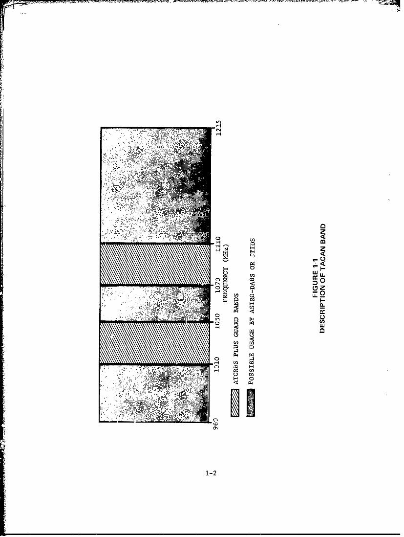
FIGURE 1-1: DESCRIPTION OF TACAN BAND 1-2
FIGURE 4-1: DESCRIPTION OF DOWNLINK SITUATION 4-7
FIGURE 4-2: DESCRIPTION OF UPLINK SITUATION 4-13
FIGURE A-I: BLOCK DIAGRAM OF DAkTA DETECTOR A-2
TABLES
TABLE 2-1: ASTRO-DABS DOWNLINK AND UPLINK CHARACTERISTICS 2-2
TABLE 3-1" JTIDS CHARACTERISTICS 3-2
TABLE 4-1: DOWNLINK BUDGET - POWER CALCULATIONS 4-8
TABLE 4-2: DOWNLINK BUDGET - SNR CALCULATIONS 4-8
TABLE 4-3: UPLINK BUDGET - POWER CALCULATIONS 4-14
TABLE 4-4: UPLINK BUDGET - SNR CALCULATIONS 4-14
TABLE 5-1: DOWNLINK PEPFORMANCE 5-2
TABLE 5-2: UPLINK PE, FORMANCE 5-3
viii
1 . INTRODUCTION
The availability of sufficient frequency spectrum ir the Aeronautical
L-band (1540 MHz - 1660 MHz) has been assumed in developmeiLt of the
ASTRO-DABS concept to date. However, significantly increased usage
of this frequency band is expected (e.g., by GPS, MARISAT, and
AEROSAT). An alternate choice for operating ASTRO-DABS is the
TACAN band (960 MHz - 1215 MHz), over which the FAA has been given
first preference. Currently, the military is also considering
employment of the TACAN band for the Joint Tactical Information
Distribution System (JTIDS). A description of proposed usage is
presented in Figure 1-1. Since JTIDS has been designed to perform
satisfactorily in the presence of jamming, the co-presence of
ASTRO-DABS does not affect it. Because of JTIDS characteristics,
however, the nerformance of ASTRO-DABS may be Impaired.
4 The present report presents a preliminary analysis of JTIDS
effects on ASTRO-DABS, together with the associated findings.
Section 2 describes the potential areas of concern, Section 3
provides a description of the pertinent aspects of JTIDS, and
Section 4 contains the analysis and calculations. The report
concludes with Section 5 which contains a discussion of results
and areas for possible further investigation.
* The frequency spectrum requirements of JTIDS are desc:ibed further in
Section 3.
1-1
C1
zzW4 0
C-,
~~ I4Hc
U) U)
PL4
1-2
2. AREAS OF CONSIDERATION
While ASTRO-DABS consists of several modes of operation (e.g.,
Tracking, Acquisition, Navigation) the system aspects to be invest-
igated may be separated into the portions: a) Downlink (Satellite-
to-Aircraft) transmissions, and b) Uplink (Aircraft-to-Satellite)
transmissions. The specific areas of Lonsideration are listed in
Table 2-1 and briefly described in the following:
2.1 Downlink Transmissions
Of primary importance in all downlink transmissions is the achieve-
ment of synchronization Irom the 60 us sync burst that is con-
sidered in each message set preamble. The sync burst is followed
by 10 data bits which specify the mode of operation (e.g., Tracking)
a gap time of 75 ps, and finally the specific mode information.
Downlink transmissions also contain messages of varying lengths.
Each message consists of a string of 1.5 is deta bits. Examples
of message lengths are: 10 bits for mode specification, 3 bits
for address group specification during Acquisition, and 31, 56, or
84 bits for address plus PWI, IPC, or ATC messages during Tracking.
Finally, Navigation messages consist of both data and timing
transmissions. The data portion provides information such as ion-
ospheric excess delay corrections. while the timaing portion
consists of several 180 ps coded timing pulses (120 bits). The
pulses are generated by each one of the visible satellites and
the aircraft derives time-of-arrinial (TOA) differences from which
to calculate position.
2.2jUplink Transmissions
Aircraft replies to Tracking and Acquisition mode interrogations
are of interest here. The Acquisition response consists of a sync
burst (67.5 -us) followed by aircraft address bits (97.5 us). The
Tracking mode response is comprised of a 33 us ranging sequence,
2-1
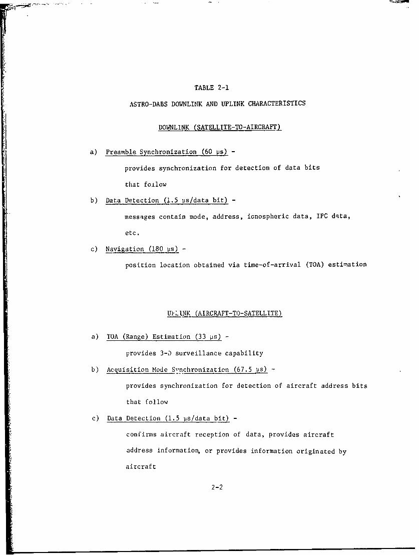
TABLE 2-1
ASTRO-DABS DOWNLINK AND UPLINK CHARACTERISTICS
DOWNLINK (SATELLITE-TO-AIRCRAFT)
a) Preamble Synchronization (60 ps) -
provides synchronization for detection of data bits
that foilow
b) Data Detection (1.5 ps/data bit) -
messages contain mode, address, ionospheric data, IPC data,
etc.
c) Navigation (180 vs) -
position location obtained via time-of-arrival (TOA) estimation
U IINK (AIRCRAFT-TO-SATELLITE)
a) TOA (Range) Estimation (33 ps) -
provides 3-D surveillance capability
b) Acquisition Mode S-nchronization (67.5 iis) -
provides synchronization for detection of aircraft address bits
that follow
c) Data Detection (1.5 ps/data bit) -
confirms aircraft reception of data, provides aircraft
address information, or provides information originated by
aircraft
2-2
from which synchronization, TOA and, hence, range information is
derived by the ground facilities. This is followed by a surveil.-
lance message, that is either 9 Vs, 51 ps, or 93 ps in duration,
which contains the data bits received by the aircraft during the
interrogation process. An incorrect detection of any data bit
would necessitate a retransmission to that aircraft at the next
cycle, some 4-5 seconds later.
2-3
i
3. DESCRIPTION OF JTIDS
JTIDS messages are transmitted in blocks of 7.8 ms and consist of
a sync burst, followed by the pertinent data, and finally a guard
or gap time. In accordance with JTIDS specifications, the average
gap time is approximately 3.8 ms or roughtly 48% of each 7.8 ms
message block.
JTIDS chip durations are ncriinally 0.2 Us, which corresponds to
a chip bandwidth cf 10 MHz. During each 7.8 ms transmission
period information is conveyed by 6.4 us message b1oaks, which
are encoded via pseudo-random noise techniques with successive
message blocks separated by 6.6 11s; the modulation scheme is
Continuous Phase Shift Modulation (CPSM). To assure additional
security in the transmission process frequency hopping is also
employed. Fifty-one frequencies are employed in the TACAN band
with a 3 MHz separation between frequencies except for 20 Miz
guard bands around tha ATCRBS frequencies 1030 MHz and 1090 MHz
(rigure 1-1). With respect to ASTRO-DABS, all JTIDS frequen-
cies occur with equal probability at all times. JTIDS character-
istics are summarized in Table 3-1.
3-1
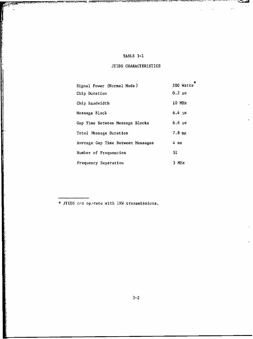
TABLE 3-1
JTIDS CHARACTERISTICS
Signal Power (Normal Mode) 200 Watts
Chip Duration 0.2 Vs
Chip Landwidth 10 MHz
Message Block 6.4 is
Gap Time Between Message Blocks 6.6 us
Total Message Duration 7.8 ms
Average Gap Time Between Messages 4 ms
Number of Frequencies 51
Frequency Separation 3 MHz
* JTIDS crn operate with 1KW transmissions.
3-2
4. ANALYSIS AND CALCULATIONS
4.1 Preliminaries
For this preliminary analysis, four primary assumptions are made:
1. One JTIDS data bus is operating at fu2l capacity so
that transmissions occur in each 7.8 ms block. In accordance
with Section 3, this implies that actual JTIDS signals are
present 48% of the time.
2. The JTIDS signal acts as a white noise. This is due to
the JTIDS signal power spectrtm being essentially flat over a
7 MHz bandwidth, which is larger than that of ASTRO-DABS
(5.33 MHz). The corresponding power spectral density is then6
obtained by dividing the JTIDS power by 7 x 10
3. There are three adjacent frequency bands that can overlap
a given ASTRO-DABS band. Because the JTIDS frequency separ-
ition is 3.0 MHz, with its nominal bandwidth almost twice that
of ASTRO-DABS, it follows that the upper and lower JTIDS
bands, relative to one which is centered on the ASTRO-DABS
frequency, will also overlap ASTRO-DABS. These sidebands
are also assumed to appear as white noise to ASTRO-DABS,
although this is not precisely the cage.
4. The average distance between a JTIDS emitter and an
ASTRO-DABS aircraft is 10 nmi. This 10 mile average figure
was chosen arbitrarily but can be used as a baw s for
comparison. Furthermore, this separation distanLe %ould not
be unreasonable if JTIDS aircraft are , .arating in the
vicinity of airports.
* The :TIDS signal here means a 6.4 ps message block and a 6.6 ps gap
time, or 13 ps total.
4-1
In all but one of the calculations, these assumptions are suf-
ficient. In one case, however, the additional assumption that
the JTIDS signal is Gaussian is made. Although this is not
actually the case, it is felt that an appropriate feel for
what may be expected is obtained via this assumption. It should
also be noted, however, that a more exact analysis does appear
pcssible. The framework for such an analysis is presented in
Appendix A.
In order to obtain numerical results on ASTRO-DABS performance
degradation, it is necessary to obtain expressions fo. proba-
bility of message error and for the timing error standard deviation
which incorporates JTIDS effects. This is accomplished in the
following subsections.
4.1.1 Probability of Message Error
An expression for probability of message error must include the
effects of interference through a specification of its strength,
statistical characterization, and probability of frequency over-
lap with ASTRO-DABS. A general expression for the probability
of message error, PM' may be written as:
PM = Pr {message errorjJTIDS overlail Pr{JTIDS overlap)
+ Pr {message errorino JTIDS overlap)Pr{no JTIDS overlap)
(4-1)
Under conditions of interest in this report, the latter term
in (4-1) will generally be insignificant* and will, therefore,
be neglected in the following. Equation (4-1) then reduces to:
eM e 'F (4-2)
*For the largest possible message of 84 data bits plus 10 mode bits,this error probability is less than 10- 4 .
4-2
where
P Pr {message errorIJTIDS overlap} (4-3)
P Pr {JTIDS overlap} (4-4)F
In accordance with the above assumptions, the probability, PF'
in a time interval, T, may be determined. Denoting by m the
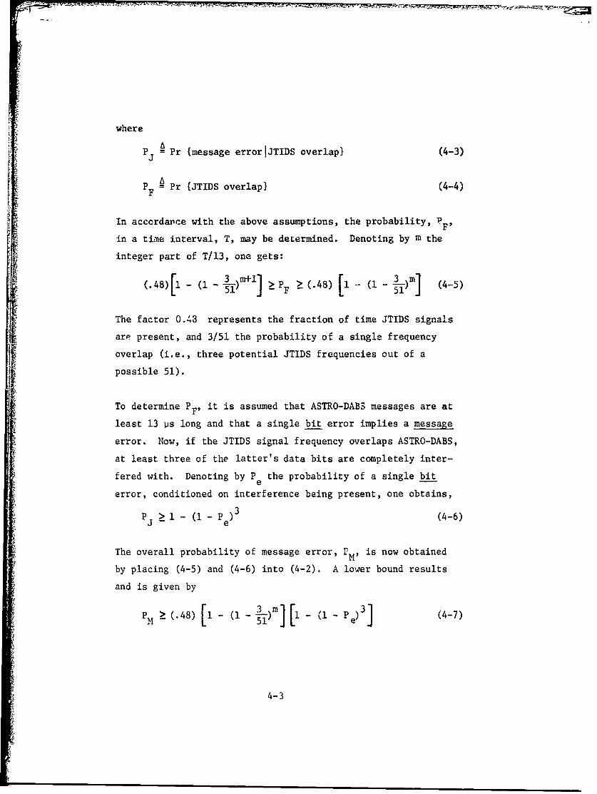
integer part of T/13, one gets:3 .r1l _P 3i m)] (-)
(.48)[1 - (1- 3)r+l] > P, > (.48) (1- 3 (45)
The factor 0.43 represents the fraction of time JTIDS signals
are present, and 3/51 the probability of a single frequency
overlap (i.e., three potential JTIDS frequencies out of a
possible 51).
To determine PF' it is assumed that ASTRO-DABS messages are at
least 13 ps long and that a single bit error implies a message
error. Now, if the JTIDS signal frequency overlaps ASTRO-DABS,
at least three of the latter's data bits are completely inter-
fered with. Denoting by P the probability of a single bite
error, conditioned on interference being present, one obtains,
P > i - (i - Pe )3 (4-6)
The overall probability of message error, rM' is now obtained
by placing (4-5) and (4-6) into (4-2). A lower bound results
and is given by
P (.48) [i - ( - I)m [1 - (i - P)] (4-7)
4-3
Equation (4-7) serves as a useful criterion for situations in
which the probability of error is relatively high. For later
calculations, it will also be desirable to have an approximate
expression for P M whic' may be applied to low probability oferror situations. This may be accomplished by first observingthat the probability of more than cne JTIDS overlap, over a
given ASTRO-DABS message duration, is generally much less than
the probability of exactly one overlap. Thus as a first
approximation, it is only necessary to determine the joint
probability of a message error and exactly one JTIDS overlap.
If one further assumes interference on four ASTRO-DABS bits,
the resulting probability of message error, PM' becomes,
PM (48) (in) 3 ( ) (1 - pe4 (4-8)M51/ 51 - el-(l-P)4 I 48
To complete the evaluations of (4-2) and (4-8), one must deter-
mine Pe' which, in turn, requires a determination of the JTInS
signal amplitude probability distribution. Appendix A considers
this problem exactly. For the present purposes, however, the
JTIDS signal is considered to be an additive White Gaussian
noise. The probability of bit error P , is then given bye
P 1 eEb/N (4-9)*
where Eb/No is the bit signal-to-noise ratio (SNR) and Nb 0 0
incorporates thermal noise and JTIDS effects.
As discussed in [3], under suitable operating conditions this resultis valid qhether or not a hard-limiter is present at the receiverfront end. Although more investigation is required, it is hereassumed that a limiter presence does not enhance or degrade performance.
4-4
4.1.2 Timng Error Standard Deviation
To minimize the effects of JTIDS intercerence on synchronization
and TOA estimation accuracies, it has been pzoposed [2] that a
hard-limiter oe included in the front enid of each ASTRO-DABS
receiver. Its presence is expected to reduce the impact of
shov: interference bursts while, hopefully, only slightly degrading
the performance of ASTRO-DABS when interference is absent.
To calculate the timina error standard deviation, aE, let a given
s',nchronization or ranging sequence contain N bits, with N bits
Laving one SNR and N2 = N - N1, bits having another. aC is then
given by,
2 2a -+ NN2 N 2 (4-10)
N1 m + N2m 2
2where T is the ASTRO-DABS chip duration. ai andm i - are given
by somewhat complex expressions [3] but may be characterized as
follows. The TOA estimate is found by searching for the peak of
the estimator output. N.m." then is the derivative of the mean,
and N1 ai he variance, of the estimator output derivative. It
should be pointed out that (4-10) does not depend on the JTIDS
signal amplitude probability distribution and is valid only if
a << T.
The advantage of employing hard-limiting can be explained with the
aid to (4-10). To do this, let N1 be the number of bits that are
interfered with. When no limiter is present the denominator of
(4-10) is independent of interference effects while the numerator
may grow without bound as the SNR over the N1 bits decreases; this
would be the case regardless of how high the SNR is over the
remaining N2 bits. When a limiter is present, however, both the
4-5
F
numerator and de',ominator of (4-10) ar: functions of SNR.
Srecifically, N1 MI ' decrease,, as its SNR increases while9
a l can increase only up to a fixed limit. Therefore, ifthe number of interference corrupted bits is sufficiently
small, the resulting degradation will also be sinall.
4.2 Downlink Performance
4.2.1 Description
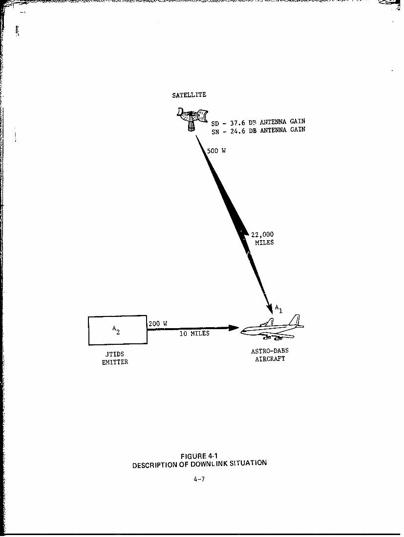
The downlink situation is described in Figure 4-1. A Surveillance/
Data Link (SD) satellite is employed for all sychronization and data
transmissions, while Surveillance/Navigation (SN) satellites dre
used for navigation timing pulse transmissions. ror calculation
purposes it is assumed that the separation between an ASTRO-DABS
(A-D) aircraft (A1) and JTIDS emitter (A2) is 10 miles. It is
further assumed, for simplicity, that the JTIDS signal acts as a
white noise over the ASTRO-DABS "andwidth. Specifically, an
examination of the JTIDS signal power spec-rnm shows it to be approxi-
mately flat over a 7 MHz bandwidth.* Thus, the corresponding
spectral density is equal to the JTIDS power received at A1 divided
by its 7 MHz bandwidth.
To determine the effects of A2 on A1 it is first necessary to calcu-
late the received A-D and JTIDS powers at the front en:1 of A1 and
form the overall link SNR. This is done in two stages as shown in
Tables 4-1 and 4-2. It should be noted that both SD and SN satellite
antenna gain values are 3 dB lower than their aeronautical L-band
equivalents [4]; this is a consequence of the lower operating
frequency considered here and the satellite antenna size remaining
constant. However, the path loss exactly compensates for this,
leaving the result the same as for the higher frequency.
* The nominal chip bandwidth is 10 MHz, corresponding to a 0.2 usnominal chip width.
4-6
'43 , .- o --. ,-
SATELLITE
S SD - 37.6 DY- ANTENNA GAIN
SN - 24.6 DB ANTENNA GAIN
500 W
22,000
MILES
JTIDS ASTRO-DABS
EMITTER AIRCRAFT
FIGURE 4-1DESCRIPTION OF DOWNLINK SITUATION
4-7
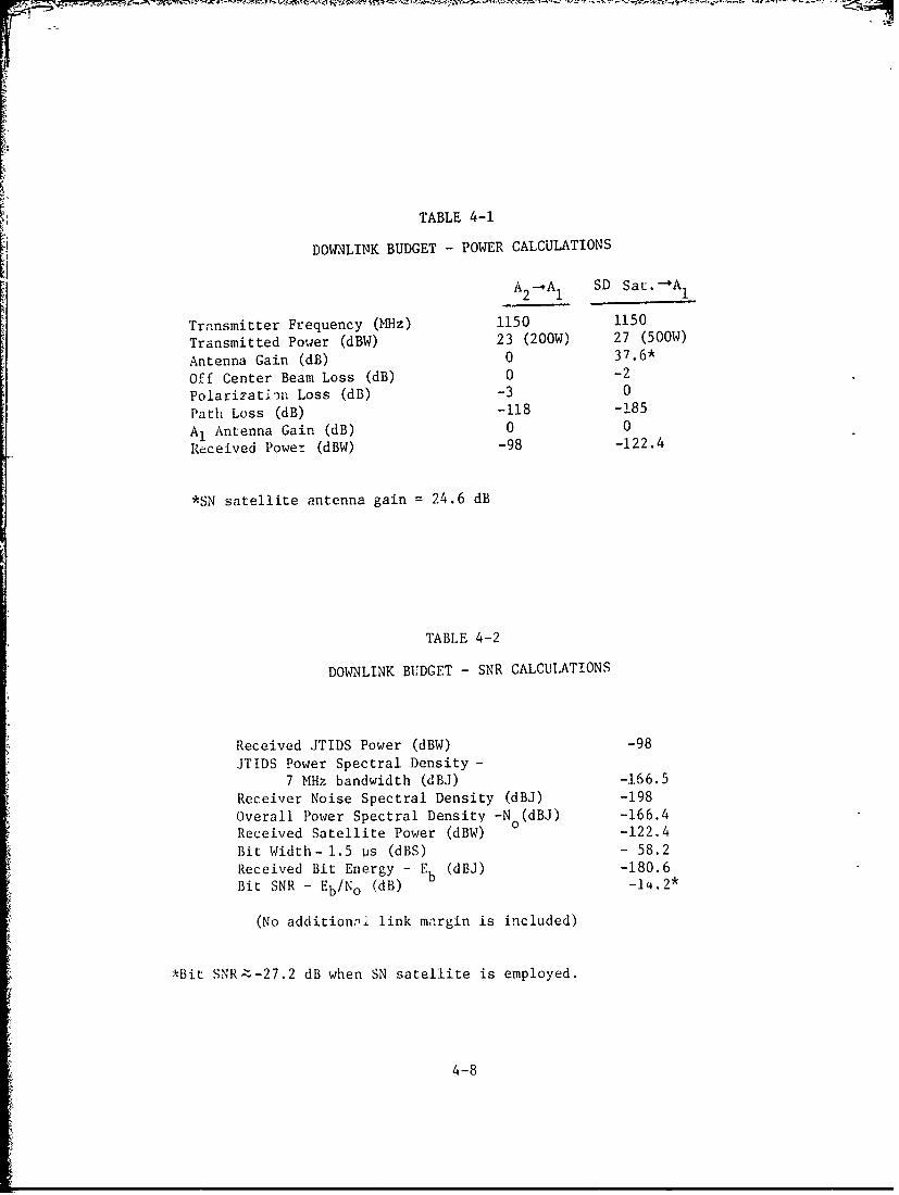
TABLE 4-1
DOWNLINK BUDGET - POWER CALCULATIONS
A2- A SD Sat.-A 1
2 1 1___
Transmitter Frequency (MHz) 1150 1150
Transmitted Power (dBW) 23 (200W) 27 (500W)
Antenna Gain (dB) 0 37.6*
Off Center Beam Loss (dB) 0 -2
Polarizati0,) Loss (dB) -3 0
Path Loss (dB) -118 -185
A1 Antenna Gain (dB) 0 0
Received Power (dBW) -98 -122.4
*SN satellite antenna gain = 24.6 dB
TABLE 4-2
DOWNLINK BUDGET - SNR CALCULATIONS
Received JTIDS Power (dBW) -98
JTIDS Power Spectral Density -
7 MHz bandwidth (dBJ) -166.5
Receiver Noise Spectral Density (dBJ) -198
Overall Power Spectral Density -N (dBJ) -166.4Received Satellite Power (dBW) 0 -122.4
Bit Width- 1.5 jis (dBS) - 58.2
Received Bit Energy - Eb (dBJ) -180.6
Bit SNR - Eb/No (dB) -i4.2"
(No additionli link margin is included)
*Bit SNR.:z-27.2 dB when SN satellite is employed.
4-8
With the aid of these link budgets specific results may now be
obtained.
4.2.2 Preamble Synchronization
The preamble sync burst is 60 us in duration and is, therefore,
composed of forty 1.5 us bits. For a 6.4 us JTIDS message block,
then, approximately 4 ASTRO-DABS bits are overlapped in time, whenever
frequency overlap occurs. To determine the standard deviation of
the synchronization timing error, a , it is necessary to employ
the following values in evaluating (4-10):
N, = 4; Sl= -14.2 dB : 0.038; N2 = 36; S2= 13 dB 12.6 (4-11)
where S. denotes the SNR over Ni bits.
The result is
o C 7.2 ns (4-12)
This compares to a a value of 5.3 ns when no interference isC
present, and no limiter is used. Clearly, a synchronization
capability has been maintained. It is interesting that syncnroni-
zation cannot be achieved if the JTIDS signal is present and no
hard-limiter is employed. The advantage of receiver front end
hard-limicing has thus been verified.
4.2.3 Navigation Timing
Navigation transmissions are i(O us long and thus contain 120 1.5 us
bits. Again, (4-10) is used to determine the standard deviation of
the timing (time-of-arrival) error. In this case,
N1 = 4; S 116; S 0.74 (4-13'
1 l.0.002 ;N 216 2 4l
* Although more than one frequency overlap can occur, with a corresponding
increase in timing error, its probability is much lcwer than that ofexactly one frequency overlap. Therefore, its effect on an overallstandard deviation result would be negligible.
** y = 11 dB is the Eb INo that would result without JTIDS (4].* Due to 13 dB lower antenna gain on SN satellite.
4-9
which leads to
a = 16.5 ns (4-14)
This compares to 14.5 ns when no interference is present and no
limiter is used. Again, the interference effects are insignifi-
cant. Futhermore, analogous to the synchronization situation,
the limiter presence prevents significant degradation of navigation
capability.
4.2.4 Data Detection
Data streams of different durations occur during satellite-to-
aircraft transmissions. Of particular interest here is the
largest Tracking mode message, which consists of 10 mode bits plus
a successive strin- of 22 address and 62 data bits. The 62 bits
contain IPC data, and correct detection of all bits is imperative.
The motivation for considering this specific message is thus clear.
A message error occurs if at least one of the 84 address plus data
bits is detected incorrectly, and its probability may be deter-
mined from (4-7). For the SNR data in Table 4-2 it can be
observed that P in (4-7) is approximately 0.5. This actuallye
is not based on any JTIDS signal distribution bu: is simply due
to thie very low bit SNR (-14.2 dB). Al2o, for the 84 bit
message, m = 9. The probability of message error then is lower
bounded by,
P m> (.48) [i - ( - )] (.5)3 ].17 (4-15)
* Some degradation in navigation accuracy does apparently result due
to the limiter presence. This can, however, be compensated byincreasing the navigation timing pulse duration accordingly.The probability of mode error is small compared to the remainingerror probability.
*** For the Gaussian White noise case, a -14.2 dB bit SNR leads to
message error, P = 0.48 = 0.5.e
4-10
In other words, when the separation between a JTIDS emitter and
an ASTRO-DABS aircraft is 10 miles, at least 17% of all IPC
messages received by that aircraft will be detected incorrectly.
The unacceptability of this result is quite apparent.
4-11
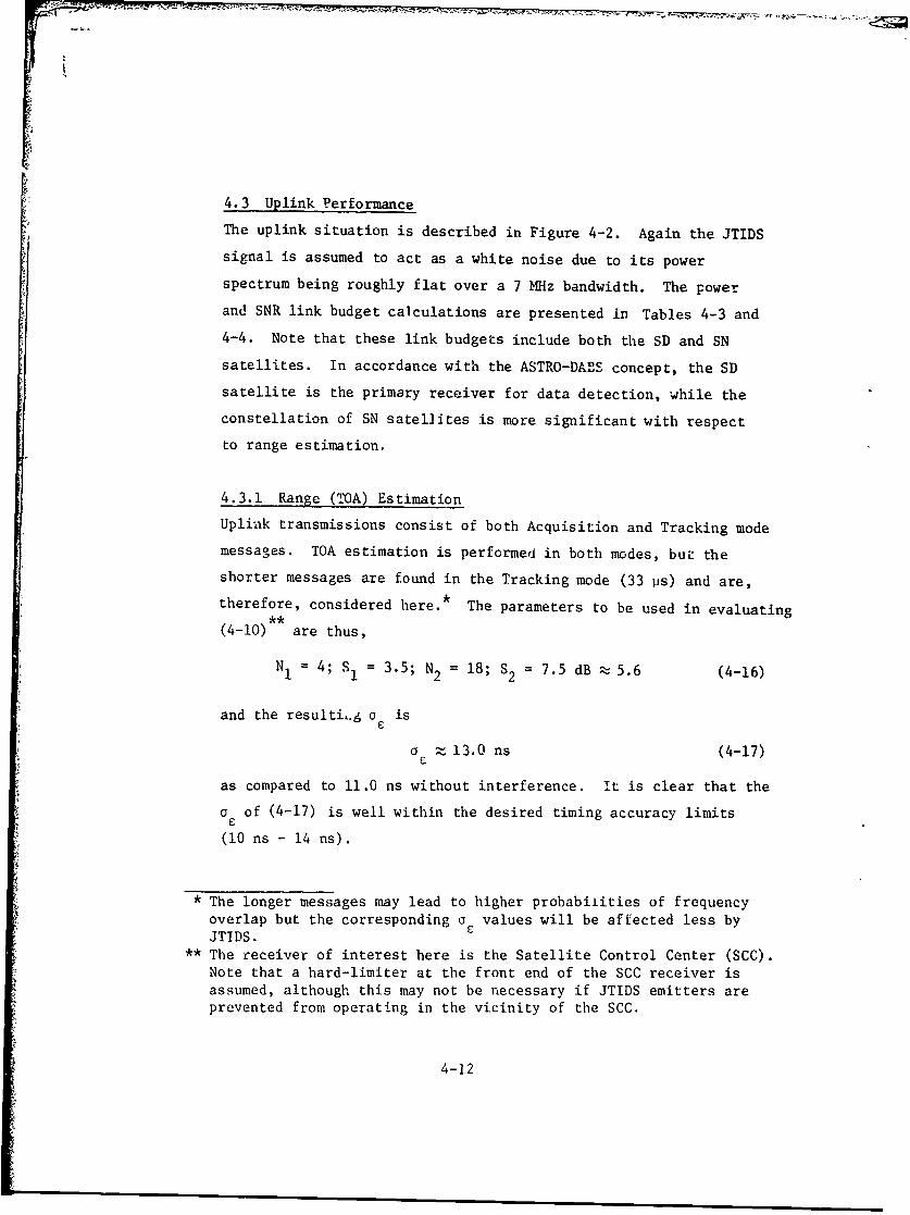
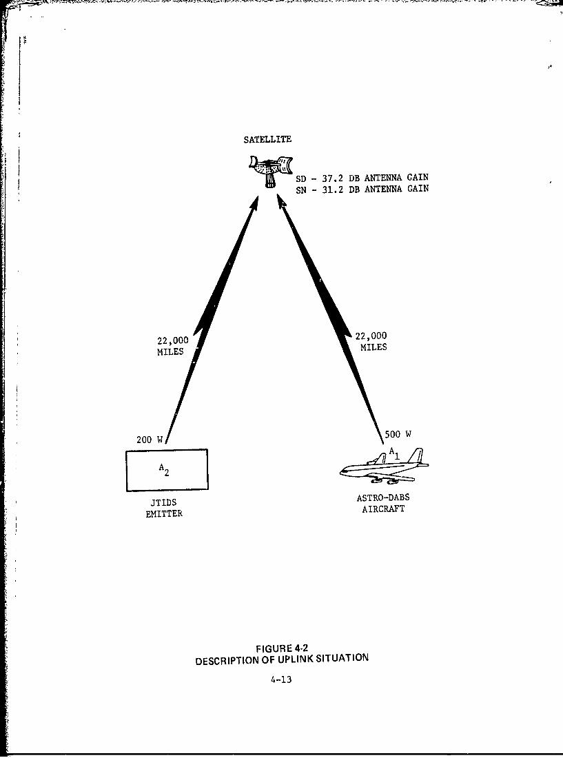
4.3 Uplink Performance
The uplink situation is described in Figure 4-2. Again the JTIDS
signal is assumed to act as a white noise due to its power
spectrum being roughly flat over a 7 MHz bandwidth. The power
and SNR link budget calculations are presented in Tables 4-3 and
4-4. Note that these link budgets include both the SD and SN
satellites. In accordance with the ASTRO-DABS concept, the SD
satellite is the primary receiver for data detection, while the
constellation of SN satellites is more significant with respect
to range estimation.
4.3.1 Range (TOA) Estimation
Uplink transmissions consist of both Acquisition and Tracking mode
messages. TOA estimation is performed in both modes, but the
shorter messages are found in the Tracking mode (33 ps) and are,
therefore, considered here.* The parameters to be used in evaluating
(4-10) are thus,
N1 4; S1 = 3.5; N2 = 18; S2 = 7.5 dB ; 5.6 (4-16)
and the resulti,.g a is
a 13.0 ns (4-17)
as compared to 11.0 ns without interference. It is clear that the
a of (4-17) is well within the desired timing accuracy limits
(10 ns - 14 ns).
* The longer messages may lead to higher probabilities of frequencyoverlap but the corresponding a values will be affected less byJTIDS.
** The receiver of interest here is the Satellite Control Center (SCC).Note that a hard-limiter at the front end of the SCC receiver isassumed, although this may not be necessary if JTIDS emitters areprevented from operating in the vicinity of the SCC.
4-12
$ I ,
SATELLITE
~SSD - 37.2 DB ANTENNA CAIN
SN - 31.2 DB ANTENNA GAIN
22,000 22,000
MILES MILES
200 W 500 W
JTIDS ASTRO-DABS
EMITTER AIRCRAFT
FIGURE 4-2DESCRIPTION OF UPLINK SITUATION
4-13

TABLE 4-3
UPLINK BUDGET - POWER CALCULATIONS
A1 -SD AI -4 SN A -1SD A2-.#SN
Transmitter Frequency (MHz) 1100 1100 1100 1100
Transmitted Power (dBW) 27(500W) 27(500W) 23(200W) 23(200W)Antenna Gain (dB) 0 0 0 0Off Center Beam Loss (dB) -2 -3 -2 • -3Polarization Loss (dB) 0 0 -3 -3Path Loss (dB) -185 -185 -185 -185Satellite Antenna Gain (dB) 37.2 31.2 37.2 31.2Received Power (dBW) -122.8 -129.8 -129.8 -136.8
TABLE 4-4
UPLINK BUDGET - SNR CALCULATIONS
SD SN
Received JTIDS Power (dBW) -129.8 -136.8JTIDS Power Spectral Density -
7 MHz Bandwidth (dBJ) -198 -205Receiver Noise Spectral Density (dBJ) -201 -201Overall Power Spectral Density -N (dBJ) -196 -199.5
0Received ASTRO-DABS Power (dBW) -122.8 -129.8Bit Width- 1.5 ps (dBS) - 58.2 - 58.2Received Energy -E (dBJ) -181 -188Bit SNR - E/No (dB) 15 11.5Additional Link Margin (dB) 6 6Net Bit SNR (dB) 9 5.5
4-14
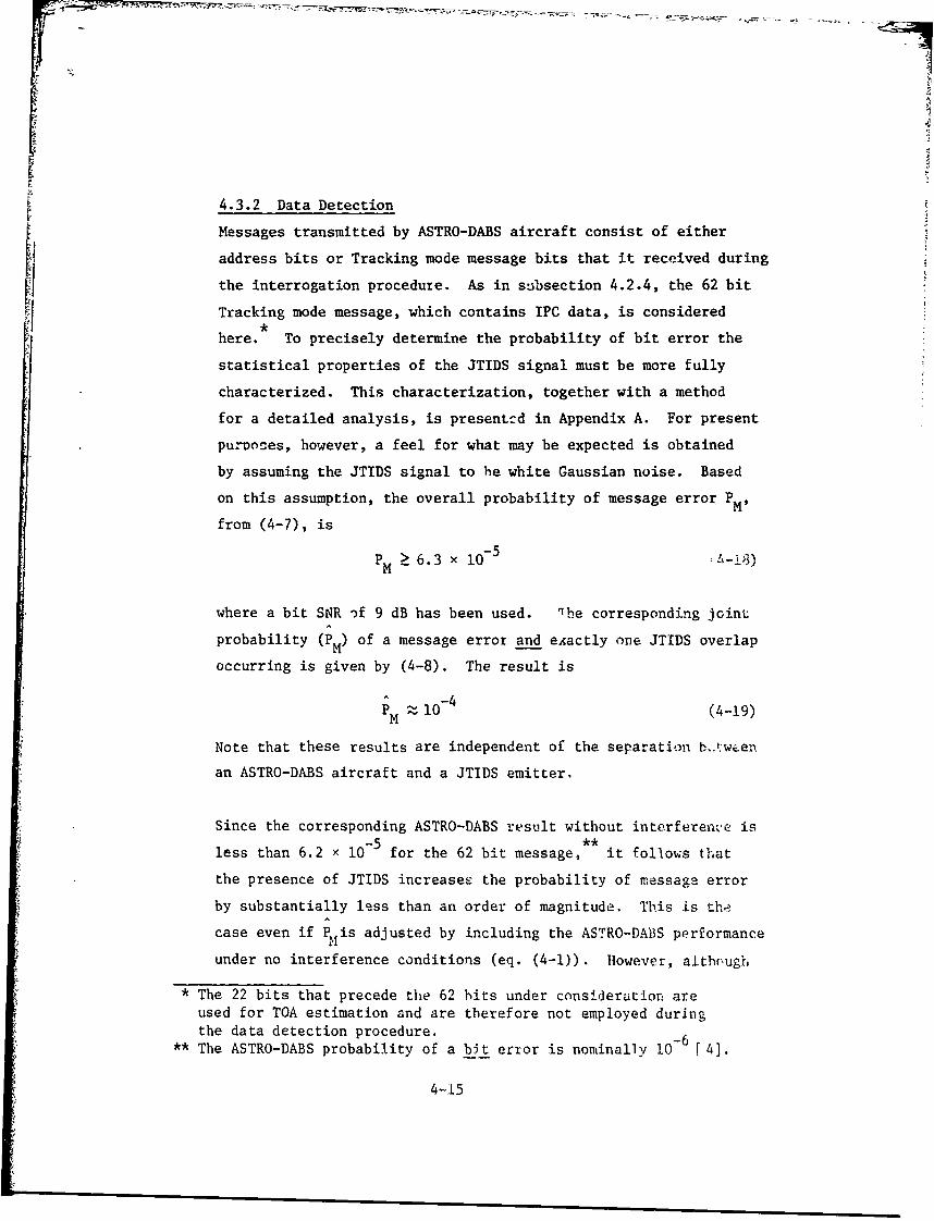
4.3.2 Data Detection
Messages transmitted by ASTRO-DABS aircraft consist of either
address bits or Tracking mode message bits that it received during
the interrogation procedure. As in subsection 4.2.4, the 62 bit
Tracking mode message, which contains IPC data, is consideredhere. To precisely determine the probability of bit error the
statistical properties of the JTIDS signal must be more fully
characterized. This characterization, together with a method
for a detailed analysis, is presentcd in Appendix A. For present
purDoses, however, a feel for what may be expected is obtained
by assuming the JTIDS signal to he white Gaussian noise. Based
on this assumption, the overall probability of message error PM'
from (4-7), is
PM 5 6.3 x 10- 5 -18)
where a bit SNR of 9 dB has been used. 'he corresponding joint
probability (PM) of a message error and eAactly one JTIDS overlap
occurring is given by (4-8). The result is
-~-4PM 1 0 (4-19)
Note that these results are independent of the separation t.°,:w'en
an ASTRO-DABS aircraft and a JTIDS emitter.
Since the corresponding ASTRO-DABS result without interferenre is
less than 6.2 x 10- 5 for the 62 bit message, it follows that
the presence of JTIDS increases the probability of messago error
by substantially less than an order of magnitude. This is the
case even if P is adjusted by including the ASTRO-DABS performance
under no interference conditions (eq. (4-1)). However, although
* The 22 bits that precede the 62 bits under consideration are
used for TOA estimation and are therefore not employed duringthe data detection procedure. -6
** The ASTRO-DABS probability of a bt error is noninally 10 [4].
4-15
the interference effects appear minor, it must be recalled that
several simplifying assumptions relating to JTIDS characteristics
were used in deriving these results. Furrhermore, I KW JTIDS are
also possible. It thus, appears that some additional investigation
may still be required.

5. SUMMARY
A preliminary investigation on the possible effects the Joint
Tactical Information Distribution System (JTIDS) may have on the
various operating modes of ASTRO-DABS, has been carried out. A
situation, in which a single JTIDS data bus is operating at full
capacity, was assumed. As a simplifying assumption, the JTIDS
signal was considered to be a white noise over the ASTRO-DABS
bandwidth. The additional assumption that the JTIDS signal is
Gaussian, was made for only one of the several situations examined.
The evaluations were partitioned into the two classes: Satellite-
to-Aircraft (Downlink) and Aircraft-to-Satellite (Uplink). A
summary of results is presented in Tables 5-1 and 5-2, along with
typical ASTRO-DABS performance in the absence of interfereace and
absence of front end hard-limiting.
The tabulated results, which correspond to 200 Watt JTIDS trans-
missions, indicate that JTIDS could cause potentially severe degrad-
ation on the downlink portion of ASTRO-DABS, with uplink degrad-
ation small but still somewhat in question. The downlink
observation is of primary interest and is due t Lhe fact that
critical downlink messages may be detected incorrectly, under
the 10 mile separation assumption. In fact, calculations using
(4-8) show that even a 0.001 probability of message error (84
bits)--the adequacy of which may be questionable--requires a down-
link bit SNR of 7.6 dB, which corresponds to a separation of at
least 100 miles.
*When 1 KW JTIDS transmissions are present, both ullnk and dowmlinkdata detection performances deteriorate further, although timingoperations are only negligibly affected.
5-1
5. SUMMARY
A preliminary investigation on the possible effects the Joint
Tactical Information Distribution System (JTIDS) may have on the
various operating modes of ASTRO-DABS, has been carried out. A
situation, in which a single JTIDS data bus is operating at full
capacity, was assumed. As a simplifying assumption, the JTIDS
signal was considered to be a white noise over the ASTRO-DABS
bandwidth. The additional assumption that the JTIDS signal is
Gaussian, was made for only one of the several situations examined.
The evaluations were partitioned into the Lwo classes: Satellite-
to-Aircraft (Downlink) and Aircraft-to-Satellite (Uplink). A
summary of results is presented in Tables 5-1 and 5-2, along with
typical ASTRO-DABS performance in the absence of interfereace and
absence of front end hard-limiting.
The tabulated results, which correspond to 200 Watt JTIDS trans-
missions, indicate that JTIDS could cause potentially severe degrad-
at!on on the downlink portion of ASTRO-DABS, with uplink degrad-
ation small but still somewhat in question. The dowmlink
observation is of primary interest and is due t Lhe fact that
critical downlink messages may be detected incorrectly, under
the 10 mile separation assumption. In fact, calculations using
(4-8) show that even a 0.001 probability of message error (84
bits)--the adequacy of which may be questionable--requires a down-
link bit SNR of 7.6 dB, which corresponds to a separation of at
least 100 miles.
* When 1 KW JTIDS transmissions are present, both unlink and Zownlinkdata detection performances deteriorate further, although timingoperations are only negligibly affected.
5-1
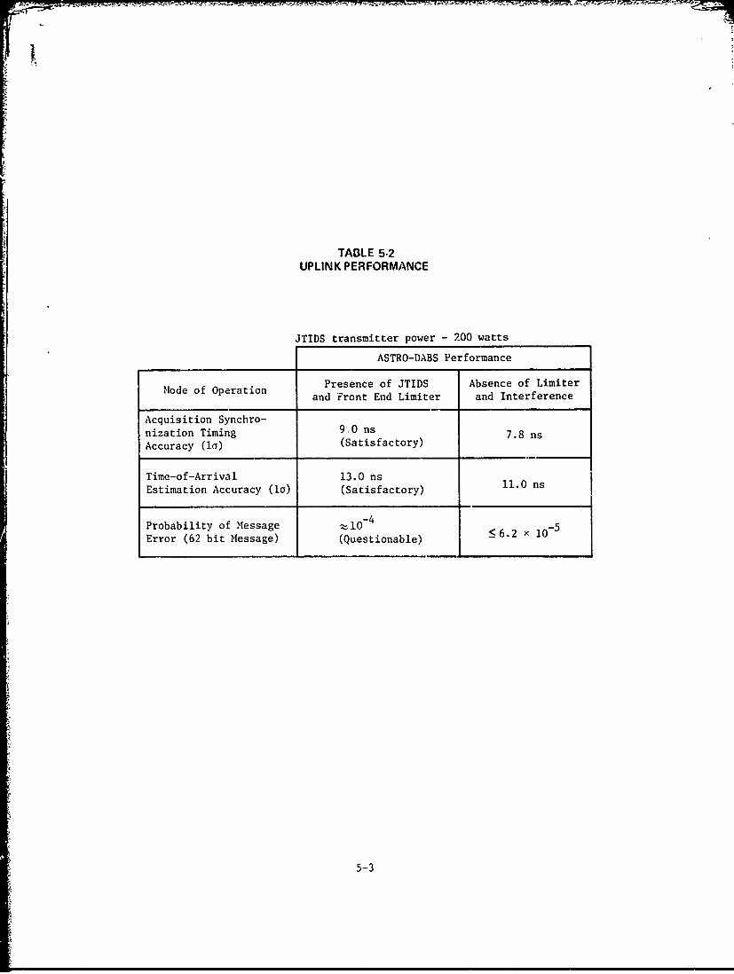
TABLE 5-2UPLINK PERFORMANCE
JTIDS transmitter power - 200 watts
ASTRO-DABS Performance
Presence of JTIDS Absence of LimiterMode of Operation and Front End Limiter and Interference
Acquisition Synchro-nization Timing 9.0 ns 7.8 nsAccuracy (i) (Satisfactory)
Time-of-Arrival 13.0 ns 11.0 nsEstimation Accuracy (i) (Satisfactory)
Probability of Message : 10-4
Error (62 bit Message) (Questionable) 62 ×
5-3
For other message lengths and modes of operations, downlink message
error probabilities differ from the oue corresponding to the above
situation. For example an Acquisition mode message error prob-
ability exceeds 0.035. Accordingly, careful consideration must
be given to the several modes of ASTRO-DABS and how sensitive
they are to system malfunctions. Specifically, if downlink data
transmission is obstructed by JTIDS, examples of possibilities
which present themselves are:
a) Aircraft may reply out of turn in the Acquisition mode
thus increasing garble, or they may not reply at all.
b) During the Tracking mode, reinterrogations of aircraft
may be necessitated more often than the nominal rate.
Both a) and b) can potentially lead to severe complications if they
cause longer acquisition times and additional interrogations,
since the capacity of ASTRO-DABS may be diminished. Furthermore,
as noted above, separations exceeding 100 miles may be required
for satisfactory interference rejection--a separation which may
be difficult to guarantee.
It would appear that further investigation iato the above matter
is required. Such a study should include the following elements:
a) More exact analysis as outlined in Appendix A.
b) Further specification of JTIDS aircraft distribution
around CONUS.
c) Further specification of overall time usage of JTIDS.
d) Additional impact of several coexisting JTIDS buses.
e) Additional impact of 1 KW JTIDS transmissions.
f) Possible remedies if interference is in fact severe
(e.g., assured frequency separation).
5-4
i60
With respect to f), it should be emphasized that methods such
as error correction and employment of longer messages do not
appear to be feasible alternatives since they would immediately
reduce ASTRO-DABS capacity. Increased transmitter powers and
antenna gains also may not plausible due to system coverage
regions and cost considerations.
5-5
APPENDIX A
ELEMENTS OF DETAILED ANALYSIS WHICH INCLUDESJTIDS EFFECTS
Let the receiver pertain to either an ASTRO-DABS safellite or air-
craft. In either rase Lae received signal, at any instant of time,
may be written as
r(t) = k A cos (wt + 8) + B cos [wt + A(t) + d] J-n(t) (A-1)
where elements on the right pertain to the ASTRO-DABS signal, JTIDS
signal* and the receiver noise, respectively. Also, k denotes the
polarity of the ASTRO-DABS chip being received while 6(t) equals
either (+ wt/2T) or (- 7t/2T), where T is the JTIDS chip width.
Furthermore, for the data detection process, it is assumed that
ASTRO-DABS chip transition times are known, while those pertaining
to JTIDS are, of course, not known. Finally, e and are independent
random variables, uniformly distributed in (-i,, 7r).
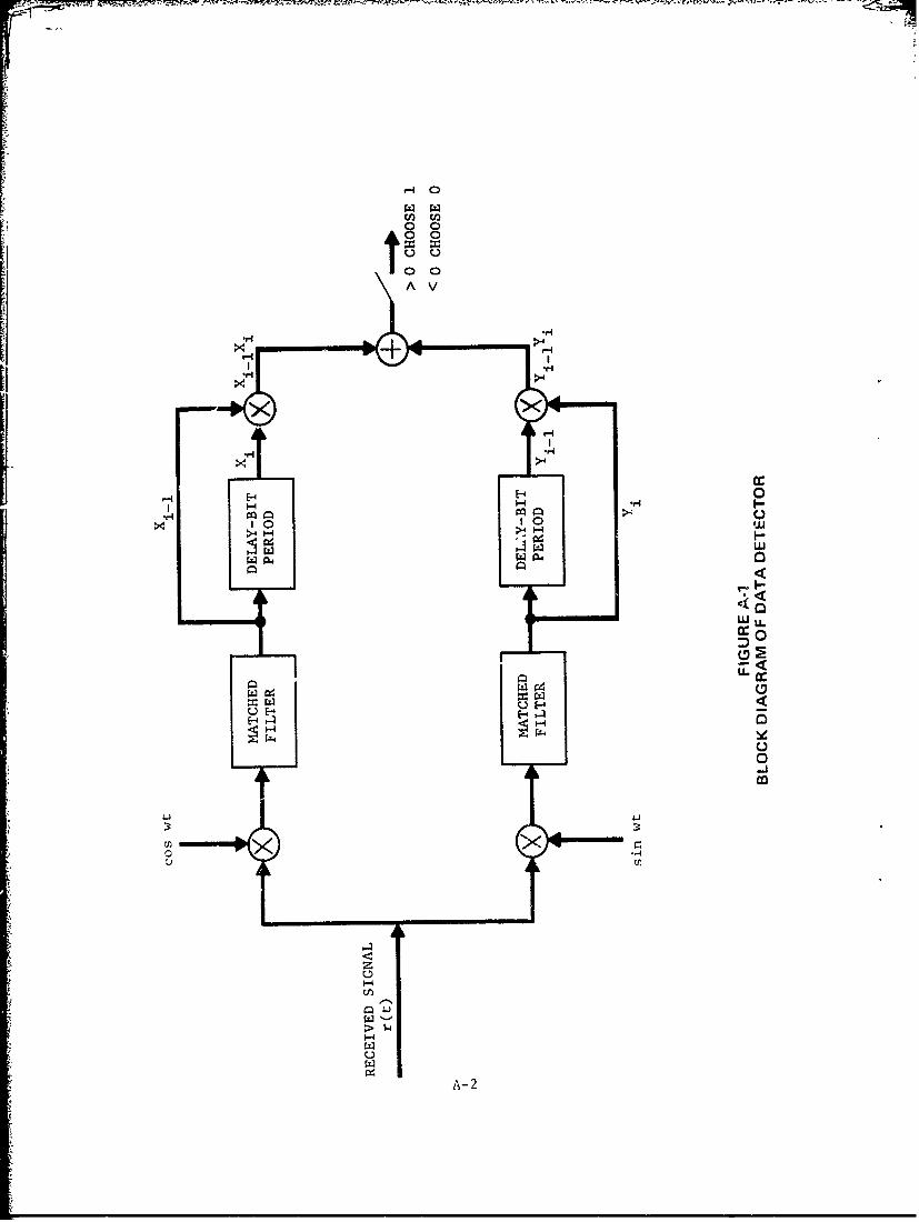
The demodulation procedure is described in Figure A-1. For simplicity
here all pulse waveshapes are assumed to be rectangular. The fol-
lowing is readily obtained from Figure A-I:
12 AfT
cos [A(t) + ] dt + n (A-2)X i li cos 0 + 2 o c i
A B (T
Y =k sine + sin [A(t) + dt + n (A-3)i i2 2i 0 si
where T is the bit period, and nc and n are independent zero mean
Gaussian random variables, each with variance N T/4. Now,
JTIDS employs CPSM, which is a form of frequency shift keying.
A--i
00
VI
rq.>w
1- 0
W LL
C0
L-4:,
0
41i
z
A- 2
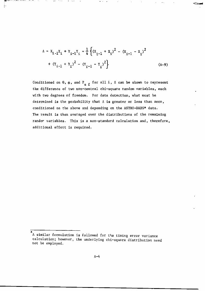
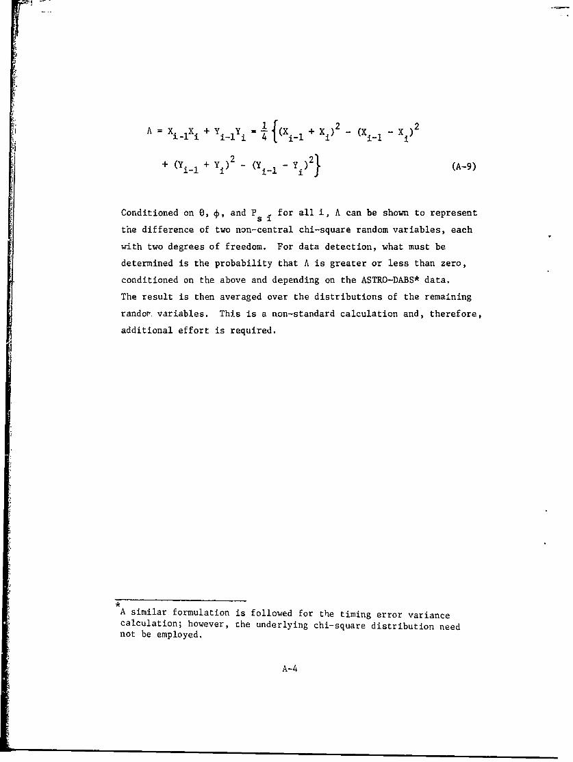
A =XiX i + i = (X 1 + Xi) 2 (X 1 - 2
+ (Yi-i + Yi ) 2 _ (Yi-i - Yi)2} (A-9)
Conditioned on 0, 4, and P s for all i, A can be shown to represent
the difference of two non-central chi-square random variables, each
with two degrees of freedom. For data detection, what must be
determined is the probability that A is greater or less than zero,
conditioned on the above and depending on the ASTRO-DABS* data.
The result is then averaged over the distributions of the remaining
randor variables. This is a non-standard calculation and, therefore,
additional effort is required.
A similar formulation is followed for the timing error variancecalculation; however, the underlying chi-square distribution neednot be employed.
A-4
A = X. X + Y Yi = (X + X - (X 2
'I i i-i 1 4 f i-l --~~i i
+ (Yi-i + Yi) - (Yi-i - Yi )21 (A-9)
Conditioned on 0, 4, and P for all i, A can be shown to represent
the difference of two non-central chi-square random variables, each
with two degrees of freedom. For data detection, what must be
determined is the probability that A is greater or less than zero,
conditioned on the above and depending on the ASTRO-DABS* data.
The result is then averaged over the distributions of the remaining
randor. variables. This is a non-standard calculation and, therefore,
additional effort is required.
A similar formulation is followed for the timing error variancecalculation; however, the underlying chi-square distribution neednot be employed.
A-4