a novel central voltage-control strategy for smart lv...
TRANSCRIPT
adfa, p. 1, 2011. © Springer-Verlag Berlin Heidelberg 2011
A Novel Central Voltage-Control Strategy for Smart LV
Distribution Networks
Efrain Bernal Alzate, Qiang Li, Jian Xie
Institute of Energy Conversion and Storage, University of Ulm, Germany [email protected], [email protected], [email protected]
Abstract. With the inclusion of Information and Communication Technology (ICT) components into the low-voltage (LV) distribution grid, some measure-ment data from smart meters are available for the control of the distribution networks with high penetration of photovoltaic (PV). This paper undertakes a central voltage-control strategy for smart LV distribution networks, by using a novel optimal power flow (OPF) methodology in combination with the infor-mation collected from smart meters for the power flow calculation. The pro-posed strategy can simultaneously mitigate the PV reactive power fluctuations, as well as minimize the voltage rise and power losses. The results are very promising, as voltage control is achieved fast and accurately, the reactive power is smoothed in reference to the typical optimization techniques and the local control strategies as validated with a real-time simulator.
Keywords: Smart grid · Renewable energy integration · PV power forecasting · Smart meter · Power system state estimation · LV Distribution Networks · ICT
1 Introduction
As the penetration of residential and commercial PV increases into electrical distribu-tion systems, an actual trend in the south of Germany, problems such as voltage rise, overloading of network equipment, harmonic current emissions, network resonance, false islanding detection, and dc current injections are becoming more of an issue to be addressed carefully [1]. Concrete solutions for secure and reliable integration of distributed PV generation into distribution systems are a fundamental concern for both academia [7], [4], [6] and industry [8], [32], [19].
A wide range of research projects have focused their efforts particularly on study-ing how to develop reverse power flow or voltage rise regulation methods to allow this integration. Conventional control mechanisms for distribution voltage regulation are: Voltage control on the feeder by using on-load tap-changing transformers (OLTC) [33], [34], [28], and fixed or switched capacitors to offset the reactive power demand from the load and thus reduce the current flow through the feeder and the related voltage drop [5], [35], [19].The problem with OLTC transformers or voltage regulators is that, the amount of permissible voltage increase is limited if there is a

load near the voltage regulator, a common case in LV distribution networks, so addi-tional voltage regulators along the feeder may be necessary.
On the other hand, it is also questionable whether the capacitor bank technology is sufficient to answer these challenges, because it may require faster and more flexible control systems than the achievable with capacitor banks [35].
Another potential solution is the use of PV inverters' reactive power as a promising inexpensive concept to resolve the problems caused by PV penetration. Its develop-ment and realization attract research efforts in a fairly large number of issues ranging from modeling [3], [8] to implementation [32], [36].
Originally, researchers focused their attention on local or decentralized voltage-control approaches. Nonetheless, in the last few years, optimization techniques to support central control strategies have been proposed, using deterministic optimiza-tion methods [13], [24,25], [27]; non-deterministic optimization methods [20], [23]; and hybrid methods [26], [31].
Central control strategies are demonstrated to be able to resolve voltage violation in LV distribution systems. However, it has repeatedly been shown that these methods may produce unwanted reactive power fluctuations [10], [25], [27,28]. If the PV penetration is large and widespread, this may also affect subtransmission and trans-mission systems. This can have important economic impacts and technical implica-tions for distribution substations and transmission lines, such as increasing losses and line loading and so on [9].
At this aim, in this paper a novel central voltage-control strategy is proposed. It is based on optimal reactive power control of smart three–phase solar inverters and the analysis of the data received from the smart meter to solve the OPF. The proposed optimal formulation, which simultaneously minimizes the magnitude of the voltage rise and reduces the power losses, includes a function to smooth the reactive power output of the inverters to improve the power quality in LV distribution network. The remainder of this paper is organized as follows. Section II presents the structure of the PV control strategy. The experimental setup and simulation results are illustrated in Section III. Section IV describes the conclusions drawn from the study carried out in this paper and suggests some guidelines for the future work.
2 PV control strategy
The main strategies to control PV systems can be classified as: Local, decentral-ized and central control strategies [29].
Local control schemes (also known as droop-based regulation strategies) make autonomous control of the reactive power supply via characteristic curves.
Decentralized control is based on the control of the reactive power of PV and the interaction with the OLTC transformer in the substation. In this case, some local communication is necessary to enable the interaction between the inverters and the decentralized methodology.
The central control scheme can be described as a communication based control methodology that allows optimizing the LV distribution grid operation not only lo-

cally but also regionally with a common beneficial level for producers and con-sumers.
2.1 Local voltage-control strategies
The local voltage-control strategies analyzed in this paper correspond to the proposed by German code of practice GC VDE-ARN 4105:
Power factor characteristic: cosphi(P) method . Reactive power / voltage characteristic: Q(U) method.
The cosphi(P) and Q(U) scheme are based on droop characteristic, as shown in Fig.1. In Germany, the cosphi (P) method proposes a procedure for the calculation of reactive power as a function of the active power generated by the solar systems. With a low active power of PV, the risk of voltage overshoot is low. The reactive power is then adjusted to zero. Once the real power increases to the half nominal power of the solar system, the reactive power increases linearly until the power factor of 0.95 for the case of PV with reactive power level between 3.68kVA and 13.8kVA, the typical residential case. For PV with power delivery > 30kVA the suggested pow-er factor is 0.9. Equations (1) express the cosphi(P) curve, as shown in Fig. 1.a.
cos � (�) = �
cos�1 , P < ��cos �1 + (1 − cos�1)(�� − � �� − ��⁄ ), �� < � ≤ ��
− 1 + (1 + cos�2)(�� − � �� − ��⁄ ), �� < � ≤ ��cos �2 , P ≥ ��
� (1)
On the other hand, in the Q(U) method the reactive power of the inverter is regu-lated as a function of the voltage at the coupling point, as shown in Fig. 1.b. It is worth noting that two droop ratios are available when the voltage is higher than the normal range. Besides, achieving better voltage control functions can differentiate the voltage responses of the inverters near LV transformer from the rest along the feeder, so the reactive power contributions from all inverters along the feeder can be more equally distributed as in the case of the cosphi(P) method [10]. As stated in the Ger-man GC, the droop curve for the Q(U) method is provided by the network operator. The algorithm for Q(U) method can be summarized by (2).
Q(U) =
⎩⎪⎨
⎪⎧
Qmax, U < Umin(U − U� Umin − U�⁄ ). Qmax, Umin ≤ U < U�
0, U� ≤ U ≤ U�
− (U − U� Umax − U�⁄ ). Qmax, U� < U ≤ Umax−Qmax, U > Umax
� (2)
2.2 Central voltage-control strategies
The technical effectiveness of local voltage-control strategies has been very well stud-ied. In particular, study [2] finds that many inverters have the capability of providing reactive power to the grid in order to reduce the voltage rise. Using a similar method,

study [3] and [6] find that a decentralized voltage-control strategy works just as well, via special located measurement systems, distribution OLTC transformers and con-trollable PV inverters.
Fig. 1. Characteristic reactive power curves. a. cosphi(P) curve. b. Q(U) curve.
In contrast, central control strategy aims for coordinated control of the complete LV distribution system by using the static and dynamic system information. The tar-get of this strategy is to find the OPF of the LV distribution systems with high pene-tration of PV. OPF has been the predominant method for such analysis since its intro-duction by Carpentier (1962) [12].
OPF seeks to optimize a given cost, planning, or reliability objective by controlling the power within an electrical network without violating network power constraints or system and equipment operating limits. Such as conventional power analysis, OPF determines voltage, current, and injected power throughout an electrical power sys-tem, that is, the system's state of operation. The general OPF problem is a nonlinear, non-convex, large-scale optimization problem which may contain both continuous and discrete control variables [11].
The most common OPF objective function for the case of PV integration are: Pow-er loss minimization (PLM) [14,15,16], Voltage rise minimization (VRM) [17,18,19], PV generation cost minimization (GCM) [20,21,22], and their combination as multi-objective OPF problems [10], [13], [24,25], [27].
In the case of VRM, it can be implemented with local control approaches, but the line impedances data is required for the calculation. As when it is implemented in a central control scheme, this approach becomes a similar optimization problem as the PLM strategy [13]. So, this formulation is used as reference to compare the improve-ments of the proposed central voltage-control strategy, as follows.
2.3 Proposed central voltage-control strategy
It is well known that central control strategies require the information of the grid to-pology and the characteristics of the distribution systems, as well as the current status
of the buses in terms of voltage, reactive and active power. As the dynamic infor-mation is usually only available for a few locations in the system, some distributed state estimation algorithms are required to guarantee the power flow calculation [29, 31]. However, few studies have integrated the actual ICT components of the smart LV distribution networks into the central control strategy [13], [27]. Smart meter is one of these ICT components, which is possible to avoid the necessity of complex state esti-mation algorithms.
The analysis of the information received from the smart meters allows the power flow calculation of the smart LV distribution system, as presented by the authors in [30] for the implementation of OPF for the central voltage-control methodology. To do so, the proposed control system computes the reactive reference values for the controllable PV inverters every 10 seconds by minimizing a multi-objective problem using a sequential quadratic programming algorithm developed in Matlab®.
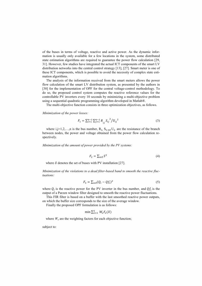
The multi-objective function consists in three optimization objectives, as follows.
Minimization of the power losses:
�� = ∑ ∑ ������� ��
����
��������
��� (3)
where i,j=1,2,…,n is the bus number, Rij, Sij and Uij are the resistance of the branch between nodes, the power and voltage obtained from the power flow calculation re-spectively.
Minimization of the amount of power provided by the PV systems:
�� = ∑ ����� (4)
where � denotes the set of buses with PV installation [27].
Minimization of the violations to a dead filter-based band to smooth the reactive fluc-tuations:
�� = ∑ (�� − ���)�
��� (5)
where �� is the reactive power for the PV inverter in the bus number, and ���is the output of a Parzen window filter designed to smooth the reactive power fluctuations.
This FIR filter is based on a buffer with the last smoothed reactive power outputs, on which the buffer size corresponds to the size of the average window.
Finally the proposed OPF formulation is as follows:
min∑ ����(�)����
where Wo are the weighting factors for each objective function; subject to:

ℎ = ����
� + ���� ≤ ��
�
���� ≤ �� ≤ ����|��| ≤ �����
�
where ���� and ���� denote voltage boundaries and ����� corresponds to the maximal reactive power provided by the PV inverter. A basic System schematic of a Smart LV distribution network with the proposed central voltage-control strategy is presented in Fig. 2.
Fig. 2. Smart LV distribution network with central voltage-control strategy.
2.4 Implementation of the central voltage-control strategy
Fig. 3a outlines the architecture of the central strategy developed. For each sample time a power flow analysis is done with the flat start conditions for voltage �� =230 + �0�, the set active power generation �� and the reactive power for the PV inverters as �� = 0���. Then, the OPF algorithm takes as reference the output val-ues of the power flow algorithm to find a feasible solution for the defined objective function and the respective restrictions.
Afterwards, the output values of the OPC algorithm are given as reference to the inverters and other load flow analysis is done to check the status of the system and giving a feedback to the OPF algorithms for the smoothing function.
Fig.3b shows the flow chart of the proposed formulation for power flow calcula-tion based on the analysis of the information provided from the smart meters. More detailed description of the power flow calculation with the smart meter information can be found in [30].

Fig. 3 Flow chart with the
3 Simulation results
3.1 LV distribution grid model
The representative LV distribution network configuration of the German power system used for the simulations and analyses with a scalable PV system. All main feeder cables are of type NYY 4x25mmhouseholds have a three230V.
The voltage at the secondary side of the transformer is considered to be 235V du
ing no load, which can be considered as a typical LV transformer tap to avoid low voltages at the end of the feeder5.5kVA including a 10% overrating, to support a reactive power compensation until 46%, even when operating with full power generation.homes instead of passive loads to improve the simulation scenarios. The German smart home load profile used in this paper is very well defined in [32].
3.2 Voltage rise and fluctuation
The voltage magnitude along feedersreactive power controland the fact that there is nothe limit of 10% as the worst case scenario,
Flow chart with the implementation of the proposed OPF strategy.
Simulation results
LV distribution grid model
The representative LV distribution network configuration of the German power system used for the simulations and analyses comprises 30 smart homes equipped
calable PV system. All main feeder cables are of type NYY 4x25mmhouseholds have a three-phase connection with a nominal line-to-neutral voltage of
The voltage at the secondary side of the transformer is considered to be 235V duing no load, which can be considered as a typical LV transformer tap to avoid low voltages at the end of the feeder. The solar installations are defined at ma5.5kVA including a 10% overrating, to support a reactive power compensation until 46%, even when operating with full power generation. The loads are defined ahomes instead of passive loads to improve the simulation scenarios. The German
home load profile used in this paper is very well defined in [32].
Voltage rise and fluctuation
oltage magnitude along feeders at the end of the simulation for the reactive power control strategies are illustrated in Fig.5. Due to the insertion of Pand the fact that there is no control law in the reference case, overvoltage occur
the worst case scenario, as shown in Fig.5a.
The representative LV distribution network configuration of the German power smart homes equipped
calable PV system. All main feeder cables are of type NYY 4x25mm2. The neutral voltage of
The voltage at the secondary side of the transformer is considered to be 235V dur-ing no load, which can be considered as a typical LV transformer tap to avoid low
The solar installations are defined at maximum 5.5kVA including a 10% overrating, to support a reactive power compensation until
The loads are defined as smart homes instead of passive loads to improve the simulation scenarios. The German
for the different rtion of PV occurs over

Fig. 4. Comparison of voltage magnitude for the differeComparison of voltage magnitude for the different control strategies.
nt control strategies.

Despite that all the inverters under cosphi(P) strategy contribute equally to the grid voltage support, the overvoltage limit is reached in the same way as the reference case with a decrease only of 8%, as shown in Fig. 5b. In the case of Q(U) method, the overvoltage is less in comparison with the cosphi(P) case, but some overvoltage is evident as seen in Fig. 5c.
As could be expected, the bus voltages in the optimization cases remain closer to the nominal value in both cases. It can be observed that the typical optimization strat-egy allows a several reduction in the voltage level around the nominal value, but the voltage magnitude presents a higher fluctuation, as shown in Fig. 5d. In the case of the proposed strategy, the voltage profiles are more homogeneous close to the refer-ences, as seen in Fig. 5e.
3.3 Network power loss
Fig. 5 provides a comparison of the power losses for the different strategies. The disparity in the power losses is gross as the PV active power injection increases. From these results, it can be seen that Q(U) strategy reaches lower power loss in compari-son with the reference case and the cosphi(P) strategy. The proposed OPF strategy has the lowest power loss, with a reduction of 67% with respect to the reference case. In the case of the Q(U) method and reference optimization strategy, the losses are almost 20% and 30% higher that the proposed strategy respectively. The reason for this is because both strategies try to maintain the voltage profile closer to the nominal volt-age magnitude value by injecting extra reactive power, as can be observed in the fol-lowing subsection.
Fig. 5. Comparison of the power losses for the different strategies.
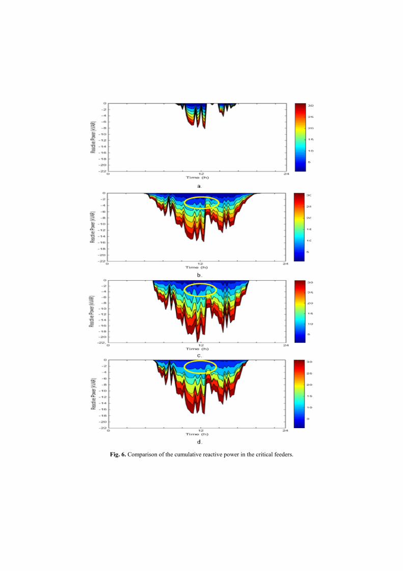
Fig. 6. Comparison of the cumulative reactive power in the critical feedersomparison of the cumulative reactive power in the critical feeders
omparison of the cumulative reactive power in the critical feeders.

3.4 Reactive power fluctuations
A comparison of the cumulative reactive power in the critical feeders is presented in Fig.6. As expected, in the case of cosphi(P) method, the injected reactive power is relative low and has the same performance for all the analyzed households, as shown in Fig. 6a. In the case of Q(U) method, as the reactive power depends on the voltage magnitude measured at its corresponding coupling point, the cumulative reactive power increases proportionally at the increasing of the PV active power injection, as shown in Fig. 6b.
Typically, the reactive power fluctuations of PV systems for the OPF case reach or exceed the performance of the PV active power injection, due to the influence of the minimization voltage rise function, which attends to deal with the deviation of the voltage magnitude even for negatives values. Fig. 6c and Fig 6d show the cumulative reactive power of the reference OPC strategy and the proposed strategy respectively.
While the reference OPC strategy and Q(U) method have similar behavior, with high reactive output power fluctuations, the proposed method significantly outper-forms the two. This observation is confirmed by Fig.7, where the reactive power out-puts of two PV inverters are shown for the proposed strategy and the reference opti-mization technique.
Fig. 7. Reactive power fluctuations.

3.5 Real-time digital simulation testing
To validate the theory which has been discussed before, a real-time simulation is per-formed, as shown in Fig. 8. The Simulink model which compares the OPF central control strategy and the Q(U) method with respect to the reference scenario is built in a host PC.
At that point, the code is compiled to the target computer to run the simulation of the smart LV distribution network in real time. Subsequently, the target computer runs the real-time simulation and sends the data, which represents the smart meter’s information, to the central controller where the reactive power for the PV inverters is calculated and sends back to the real time simulator.
Fig. 8. Real-time simulation scheme based on Simulink Real-Time™.
Figure 9 shows the results obtained from the real-time simulator. Scope 1 shows the PV solar profile simulated for 5 days. Scope 2 and 3 correspond to the RMS volt-age response of the household without control nearest and farthest to the transformer respectively.
The results obtained for the smart homes with Q(U) local control strategy are showed in the scopes 4-6, and the smart homes with OPF central control are illustrat-ed in scope 7-9. Scope 4 and 7 compare the reactive power performance of the PV inverter of the household nearest and farthest to the transformer for local and central control respectively.
As can be seen from above real-time simulation results, when the solar power goes higher, the voltage from the household without control exceeds the up limit. The re-sults obtained from the local control improves, but still exceeds the up limit during some peak solar power time period. However, on the other hand, the optimization central control not only regulates the voltage into the limit band for all solar scenarios, but also makes the voltage and reactive power profile smoother in accordance with which has been proposed in this paper.

4 Conclusion
This paper has presentedtribution networks. The fluctuation of the PV inverterslosses of the system. This is ood, because it improves damping and stability of the reactive power significantly in reference with the typical optimization techniques and the local control strategies
The results are very promising, as the mitigate the voltage rise with a better minimization of the power loss. new formulation for the power flow analysis based on meters was included and validatedtime simulator.
Fig. 9. Real-time digital simulation results.
presented a novel central voltage-control strategy for smart . The proposed strategy is designed to reduce the reactive power
of the PV inverters to improve the power quality and reduce the power This is one of the important features of the proposed OPF
it improves damping and stability of the reactive power significantly in reference with the typical optimization techniques and the local control strategies
are very promising, as the central voltage-control strategy is capable tmitigate the voltage rise with a better minimization of the power loss. Moreover, a new formulation for the power flow analysis based on the information from the smart
and validated with several simulations included a test with
control strategy for smart LV dis-proposed strategy is designed to reduce the reactive power
the power OPF meth-
it improves damping and stability of the reactive power significantly in reference with the typical optimization techniques and the local control strategies.
is capable to Moreover, a
the information from the smart several simulations included a test with a real-
5 References
1. Mihet-Popa, L., Han, X., Bindner, H., Pihl-Andersen, J., Mehmedalic, J.: Development
and modeling of different scenarios for a smart distribution grid, Applied Computational Intelligence and Informatics (SACI), IEEE 8th International Symposium on, pp. 437-442 (2013)
2. Dimeas, A., Drenkard, S., Hatziargyriou, N., Weidlich, A.: Smart Houses in the Smart Grid: Developing an interactive network., Electrification Magazine, IEEE , vol.2, no.1, pp. 81-93 (2014)
3. Casolino, G.M., Di Fazio, A.R.,Losi, A., Russo, M.: Smart modeling and tools for Distri-bution System Management and operation, Energy Conference and Exhibition (ENERGYCON), 2012 IEEE International , vol., no., pp. 635-640 (2012)
4. Haifeng Liu, Licheng Jin, Le, D., Chowdhury, A.A.: Impact of high penetration of solar photovoltaic generation on power system small signal stability, Power System Technology (POWERCON), 2010 International Conference on , vol., no., pp. 24-28 (2010)
5. Mihet-Popa, L., Han, X., Bindner, H., Pihl-Andersen, J., Mehmedalic, J.: Grid modeling, analysis and simulation of different scenarios for a smart low-voltage distribution grid, In-novative Smart Grid Technologies Europe (ISGT EUROPE), 2013 4th IEEE/PES , vol., no., pp. 6-9 (2013)
6. Tonkoski, R., Lopes, L. A. C.: Coordinated Active Power Curtailment of Grid Connected PV Inverters, IEEE Transactions on Sustainable Energy, vol. 2, no. 2, pp. 139 -147 (2011)
7. Nyborg, S., Røpke, I.: BEnergy impacts of the smart home – conflicting visions, Confer-ence proceedings, Energy efficiency first: The foundation of a low-carbon society (ECEEE), pp. 1849-1860 (2011)
8. Austrian Institute of Technology (AT): DG Demonet Smart LV Grid, AT (2011) 9. Katiraei, F., Agüero, J.R.: Solar PV Integration Challenges, Power and Energy Magazine,
IEEE , vol.9, no.3, pp. 62-71 (2011) 10. Juanperez, M., Yang, G., Kjær S.: Voltage regulation in LV grids by coordinated volt-var
control strategies, J. Mod. Power Syst. Clean Energy (2014) 11. Frank, S., Steponavice, I., Rebennack, S.: Optimal Power Flow: A Bibliographic Survey I.
Energy Syst 3, pp. 221–258 (2012) 12. Carpentier, J.: Contribution to the economic dispatch problem, Bull. Soc. Fr. Electr. (8) pp.
431–447 (1962) 13. Kabiri, R., Holmes, D.G.,McGrath, B.P.: The influence of PV inverter reactive power in-
jection on grid voltage regulation, Power Electronics for Distributed Generation Systems (PEDG), 2014 IEEE 5th International Symposium on , vol., no., pp. 24-27 (2014)
14. Ravindran, V., Aravinthan and V.: Feeder level power loss reduction through reactive power control with presence of distributed generation, pp. 1-25 (2013)
15. Golshan, M. E H, Arefifar, S.A.: Distributed generation, reactive sources and network-configuration planning for power and energy-loss reduction, Generation, Transmission and Distribution, IEE Proceedings- , vol.153, no.2, pp. 127-136 (2006)
16. Hen-Geul Yeh, Gayme, D.F., Low, S.H.: Adaptive VAR Control for Distribution Circuits With Photovoltaic Generators, Power Systems, IEEE Transactions on , vol.27, no.3, pp. 1656-1663 (2012)

17. Carvalho, P. M S,Correia, Pedro F., Ferreira, L.A.F.: Distributed Reactive Power Genera-tion Control for Voltage Rise Mitigation in Distribution Networks, Power Systems, IEEE Transactions on , vol.23, no.2, pp. 766-772 (2008)
18. Hen-Geul Yeh, Gayme, D.F., Low, S.H.: Adaptive VAR Control for Distribution Circuits with Photovoltaic Generators, Power Systems, IEEE Transactions on , vol.27, no.3, pp. 1656-1663 (2012)
19. Cagnano, A., De Tuglie, E., Dicorato, M., Forte, G., Trovato, M.: PV plants for voltage regulation in distribution networks, Universities Power Engineering Conference (UPEC), 2012 47th International , vol., no., pp. 4-7 (2012)
20. Chakraborty, S., Simoes, M.G.: PV-Microgrid Operational Cost Minimization by Neural Forecasting and Heuristic Optimization, Industry Applications Society Annual Meeting, 2008. IEEE , vol., no., pp. 5-9 (2008)
21. Budischak, C., Sewell, D., Thomson H.: Cost-minimized combinations of solar power and electrochemical storage, powering the grid up to 99.9% of the time, Journal of Power Sources, Volume 232, 15 (2013)
22. Andrew, D. Mills, Ryan H. Wiser, S.: Strategies to mitigate declines in the economic value of wind and solar at high penetration in California, Applied Energy, Volume 147, pp 269-278 (2015)
23. Golestani, S., Tadayon, M.: Distributed generation dispatch optimization by artificial neu-ral network trained by particle swarm optimization algorithm. Energy Market (EEM), 2011 8th International Conference on the European, pp. 543-548 (2011)
24. Sulc, P., Backhaus, S., Chertkov, M.: Optimal Distributed Control of Reactive Power Via the Alternating Direction Method of Multipliers, Energy Conversion, IEEE Transactions on, Volume: 29, Issue: 4, pp. 968 - 977 (2014)
25. Kundu, S., Backhaus, S., Hiskens, I.A.: Distributed control of reactive power from photo-voltaic inverters, Circuits and Systems (ISCAS), 2013 IEEE International Symposium on, vol., no., pp. 249-252 (2013)
26. Boyd S., Parikh, N., Chu E.: Distributed optimization and statistical learning via the alter-nating direction method of multipliers, Foundations Trends Mach. Learn., vol. 3, no. 1, pp. 1-122 (2011)
27. Xiangjing Su, Masoum, M.A.S., Wolfs, P.J.: Optimal PV Inverter Reactive Power Control and Real Power Curtailment to Improve Performance of Unbalanced Four-Wire LV Dis-tribution Networks, Sustainable Energy, IEEE Transactions on, vol.5, no.3, pp. 967-977 (2014)
28. Xiaohu Liu, Aichhorn, A., Liming Liu, Hui, Li.: Coordinated Control of Distributed Ener-gy Storage System With Tap Changer Transformers for Voltage Rise Mitigation Under High Photovoltaic Penetration, Smart Grid, IEEE Transactions on, vol.3, no.2, pp. 897-906 (2012)
29. von Appen, J., Braun, M., Stetz, T., Diwold, K., Geibel, D.: Time in the Sun: The Chal-lenge of High PV Penetration in the German Electric Grid, Power and Energy Magazine, IEEE , vol.11, no.2, pp. 55-64 (2013)
30. Alzate, E.B., Mallick, N.H., Jian Xie.: A high-resolution smart home power demand model and future impact on load profile in Germany, Power and Energy (PECON), 2014 IEEE International Conference on , vol., no., pp. 53-58 (2014)
31. Diwold, K., Yan, W., De Alvaro Garcia, L., Mocnik, L.,Braun, M.: Coordinated voltage-control in distribution systems under uncertainty, Universities Power Engineering Confer-ence (UPEC), 2012 47th International , vol., no., pp. 4-7 (2012)
32. Department of Energy Technology- Aalborg University, Development of a Secure, Eco-nomic and Environmentally friendly Modern Power System. DK (2010)

33. Neusel-Lange, N, Oerter, C., Intelligente Lösungen für Verteilnetze, VDE-Insidel (2012) 34. RWE, Technical University of Dortmund, ABB, and Consentec: Smart Country, Heraus-
forderungen und intelligente Lösungen für die Energiewende auf dem Land., Germany (2011)
35. Turitsyn, K., Sulc, P., Backhaus, S., Chertkov, M.: Options for Control of Reactive Power by Distributed Photovoltaic Generators, Proceedings EEE, vol. 99, no. 6, pp. 1063-1073 (2011)
36. Technische Universität München, Georg-Simon-Ohm Hochschule Nürnberg, Siemens AG, and Power Plus Communications AG, Projekt Netz," Germany (2009)