a novel algorithm for the weak gps signals acquisition
TRANSCRIPT

A Novel Algorithm for the Weak GPS Signals Acquisition
Huan Li ,Yubai Li, Wei Peng, Bolong Wen DSP Lab, School of Communication and Information Engineering,
University of Electronic Science and Technology of China ChengDu, China
[email protected] [email protected] [email protected] [email protected]
Abstract—The acquisition of weak GPS signals is a challenging problem. The current methods for acquisition of weak GPS signals mainly depend on aiding, in which the GPS receiver needs priori information from base-station to promote weak GPS signal acquisition and tracking. It is unavailable in some remote locations since the area may not be covered by the base-station. On the other hand, in the state-of-art unaided GPS receivers, the weak GPS signals acquisition requires long Pre-detection Integration Time (PIT), such that the computation is complex and time-consuming. This paper proposes a computational efficient method to speed up acquisition operations. Finally, we evaluate the efficiency of the method through simulations.
Keywords-weak GPS signals, acquisition, Blocked method,
I. INTRODUCTION
The Global Positioning System (GPS) is a space-based global navigation satellite system (GNSS) [1] that provides time information and reliable location at all times, in all weather and anywhere on or near the Earth when and where there is an unobstructed line of sight to four or more GPS satellites].GPS receivers must acquire and track the signals from several GPS satellites to calculate the position. In order to track and decode the information in GPS signals, an acquisition method must first be used to detect the presence of the signal. Once the signal is detected, the necessary parameters can be obtained and be transmitted to a tracking program. Then, the navigation data can be extracted from the tracking program. Therefore, acquisition is the first step of GPS signal processing. However, most of the GPS signal acquisition techniques, which are considered to be adequate on positioning capability in outdoor environment, are not satisfactory for application with weak signals.
GPS signal acquisition starts with a searching process [2]. The receiver down-converts RF (radio frequency) signals to IF (intermediate frequency) signals. The IF signals are sampled, digitized, and then processed by the acquisition module. The aim of the acquisition is to find the visible satellites, the C/A code delay τ and the Doppler shift fd.
The current art for acquisition of weak GPS signals is dependent upon aiding, in which the receivers are provided with a-priori information such as the approximate position of receiver, the ephemeris, navigation data and time stamp to promote signal acquisition and tracking. AGPS [3] (aided GPS) requires that the receiver contact with the source of aiding information through wireless link, which may not be
available in some locations, especially in the remote locations.
The main contributions of this paper are composed by twofold. First, we analyze the existing methods of unaided weak GPS signals acquisition. Then, a novel algorithm is proposed to speed up acquisition operations and realized on GPS software receiver.
II. SOFTWARE GPS RECEIVER ARCHITECTURE
Fig.1 shows the block diagram of Software GPS receiver [5]. In this receiver, the analog satellite signals are received at L1 band (1575.42MHz) through a RF down converter chip. This chip converts the frequency of the received signal from L1 band to IF. The IF Output is adjustable through 0MHz to 12.5MHz, then digitized at 5.714MHz sampling frequency. The USB control module provides a seamless USB interface to computer port. Then, signal processing techniques are used to extract the navigation data bits which are used to extract the user position.
Figure 1. Block Diagram of Software GPS Receiver
The sampled IF signal is modeled as [4]:
1 0
( ) ( )[(1 )( )]
cos[ ( )]
sat
sat
Nsatsat k sat k k
k ksat IF k D k
d t c t t tr A n
t t
ηω ω φ=
+ −= + × − +
(1)
Where kr is the IF signal at sample time kt . satN is the number of visible satellites. A is the signal amplitude. The function ( )sat kd t is the navigation data stream. The sequence
( )satc t is the C/A code of the received signal with a period of 1ms. The quantity η is the fractional perturbation of the chipping rate due to Doppler shift and the value of
6/(2 1575.42 10 )Dη ω π= × × . satt∧
is the start time of the C/A code, which is a measure of its phase. The frequency satDω is the nominal intermediate frequency, which is got by mixing the RF L1 carrier frequency with the local frequency, and the carrier signal’s Doppler shift. The angle 0φ is the initial carrier phase.
The 2nd International Conference on Computer Application and System Modeling (2012)
Published by Atlantis Press, Paris, France. © the authors
0738

III. UNAIDED METHOD FOR THE ACQUISITION OF WEAK
GPS SIGNALS
GPS signals are already very weak when they arrive at the Earth's surface. When GPS signals are weak, for example indoors, the extra processing power should be used to integrate weak signals to the point where they can be used to provide a position or timing solution.
The received GPS signal sensitivity is measured with reference to the carrier to noise density ratio C/N0, equivalent to the signal-to-noise ratio (SNR) in a 1Hz bandwidth [6]. Coherent integration for TI seconds acts as a low pass filter with bandwidth of BN =1/TI .If we assume the power spectral density of the noise in the received signal is N0, the total noise power following the coherent integration can be calculated as:
0N
I
NP
T= (2)
So, signal to noise ratio can be written as
0
( )RI
N
P CSNR T
P N= = (3)
Where PR is the average power density of received signals.
From formula (3), we can get that the SNR of the post-correlation signal increases linearly with the rise of integration time TI, such that the weak GPS signals acquisition requires long integration time to boost the post-correlation SNR. When the coherent integration time is a multiple of one data bit duration, a search over all data bit combinations is needed. Since the data bit duration is 20ms and the data bit edge is synchronized with the 1ms PRN code, there are twenty possible bit edge positions. Thus, besides the visible satellites, Doppler shifts and code phases, we have to search both possible data bit combinations and possible bit edge positions for weak signals. To the best of our known, Alternate Half-Bits Method[7][8], Full-Bits Method with Estimation of Bit Transition Times[7] and Double-block zero padding[9] are often used for weak GPS signals acquisition.
A. Alternate Half-Bits Method
Since navigation data is 20ms (20 C/A code long), the maximum data recorded for acquisition should be 10ms [1]. In 20ms of data there can be only one data transition at most. If one takes the first 10ms of data and there is a data transition, the next 10ms will not have one.
Figure 2. Example relationship of pre-squaring summation intervals to
data bit transitions for the alternate half-bits method
Figure 2 illustrates this method. It performs two independent acquisition calculations using alternate sets of Sk values [3]; call them set "a" and set "b". Set "a" uses S0=0, S1=20, S2=40, … , SM-1=(M-1)*20. Set "b" is displaced half a bit later than set "a": S0=10, S1=30, S2=50, … , SM-1 =10+(M-1)*20. Each pre-squaring summation interval is half a bit in duration, i.e., L=10. Thus, one of the sets is guaranteed to have no bit transitions in any of its pre-squaring summation intervals. Superimposed on the plot are the set "a" and set "b" pre-squaring summation intervals. All of the data bit transitions occur in pre-squaring intervals from set "b". The PIT statistic of set "a" would take on the largest value and, therefore, would be used to acquire the signal.
B. Full-Bits Method with Estimation of Bit Transition Times
Since one navigation data contains 20 C/A codes, there are 20 possible positions of data transition during one data. The full-bit method picks the summation intervals involving estimation of the data bit transition times [3]. Suppose the integration time TI is a multiply of M and one data bit interval, the method start indices of the pre-squaring summation intervals are set to S0=i, S1=i+20, S2=i+40, … , SM-1=i+(M-1)*20, and the duration of each summation is a full bit, L=20. The Plong detection statistic is then computed for each i in the set {0, 1, 2, … , 19}.
C. Double-block zero padding(DBZP)
DBZP [6] involves a circular correlation of the incoming signals with a copy of the baseband spreading code, a discrete Fourier transform (DFT) is then performed, following the circular correlation, to estimate the residual Doppler frequency. DBZP is one of the most advanced algorithms and thus it is especially suitable for software-defined GPS receivers.
IV. DESCRIPTION OF OUR ALGORITHM
Our algorithm is based on DBZP algorithm and it aims to reduce the computation complexity and save memory space further. Our algorithm is described as follow.
Step1: converts the received IF signal into baseband. Step2: using integration time (PIT) of TI ms, arrange the
TI-long baseband samples into blocks. Define the block size by Sblock. The number of blocks is equal to the number of Doppler bins, Nfd. The Doppler bin separation is equal to 1/TI.
Step3: divide these blocked signals into two branches, one branch is delayed by one block and the other keeps the same. Then, add these two branches point by point to get a pseudo received data.
Step4: circular correlation is calculated by using two corresponding blocks called the pseudo received data and the local PN code, respectively. The preserved points, in each block, represent a partial coherent integration of length TI/Nfd ms at Sblock possible code delays. The preserved points, in each block, represent a partial coherent integration of length TI /Nfd ms at Sblock possible code delays. The preserved points are arranged into a matrix Mc of initial size equal to Nfd × Sblock, each column contains the points located at the
The 2nd International Conference on Computer Application and System Modeling (2012)
Published by Atlantis Press, Paris, France. © the authors
0739
same index in each block, to cover all possible Nτ code delays.
Step5: calculate the FFT of each column of Mc, this will be an Nfd FFT-points operation. The result represents a TI-ms coherent integration. Each row represents the coherent integration at a possible Doppler shift, and each column represents the coherent integration at a possible code delay.
Step6: if the maximum value of the FFT component crosses the acquisition threshold γ, the corresponding position of Mc will correspond to the estimated code delay and the Doppler shift could be calculated.
Step7: calculate the Doppler shift of the received signal by the equation of below:
3FFT max
1
10 /NdI
fT −=
× (4)
Step8: if the maximum value of the FFT component below the acquisition threshold γ, shift a new block into the two branches of data and repeat the above steps.
The flow of our algorithm is shown in Fig.3.
V. SIMULATION AND RESULTS
This algorithm was developed that use a integrating time that is a multiple of one data bit interval, without the availability of any assisting information. To measure the performance of our algorithm, we test the probabilities of detection with different C/N0 and different integrating time using simulation data. The number of multiplication and memory used has been measured to verify the algorithm's availability, In these simulations, the parameters are selected based on the weak signal environment, where the C/N0 value are chosen from 15dB-Hz to 15dB-Hz and the integrating time is chosen from 50 ms to 200ms.
In order to validate the availability in real world application, we receive the GPS signal by using our receiver to verify our algorithm. A detection threshold is used to decide whether a signal is present or not.
The data is collected in an indoor area and sampled by a MAX2769 based GPS-SDR receiver. The central frequency of down-converted signal is 9.55MHz, and the sampling frequency is 38.192MHz. The software down-convert the signal to a central frequency of 10 KHz first, and then our acquisition algorithm is used to detect the GPS signal .The post detection integration is 30ms.
Figure 4. Relation between Probabilities of Detection and C/N0
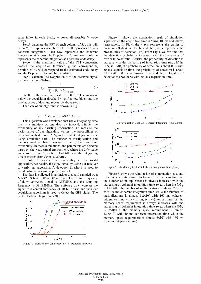
Figure 4 shows the acquisition result of simulation signals when the acquisition time is 50ms, 100ms and 200ms, respectively. In Fig.4, the x-axis represents the carrier to noise ratio(C/N0) in dB-Hz and the y-axis represents the probabilities of detection (Pd). From Fig.4, we can find that the detection probability increases with the increasing of carrier to noise ratio. Besides, the probability of detection is increase with the increasing of integration time (e.g., If the C/N0 is 18dB, the probability of detection is about 0.03 with 50 ms acquisition time, the probability of detection is about 0.13 with 100 ms acquisition time and the probability of detection is about 0.58 with 200 ms acquisition time).
(a) Multiplication Cost V.S. Coherent Integration Time (20ms)
Figure 5. (b)Memory Cost V.S. Coherent Integration Time (20ms)
Figure 5 shows the relationship of computation cost and coherent integration time. In Figure 5 (a), we can find that the number of multiplications is always increases with the increasing of coherent integration time (e.g., when the C/N0 is 15dB-Hz, the number of multiplications is almost 7.5×10⁷ with 40 ms coherent integration time while the number of multiplications is almost 1.2×10⁹ with 160 ms coherent integration time while). In Figure 5 (b), we can find that the memory space requirement is always increases with the increasing of coherent integration time (e.g., when the C/N0 is 25dB-Hz, the memory space requirement is almost 3.75×10⁸ with 40 ms coherent integration time while the memory space requirement is almost 6×10⁹ with 160 ms coherent integration time).
The 2nd International Conference on Computer Application and System Modeling (2012)
Published by Atlantis Press, Paris, France. © the authors
0740

Figure 6. Acquisition result of an indoor GPS signal
Figure 6 shows the acquisition result of a real GPS signal. The x-axis represents the signal frequency fd in KHz and the y-axis represents the power density. From Fig.6, we can find that a peak appears at 16.823 KHz, thus the Doppler frequency of the received signal is 16.823-10 = 6.823 KHz.
VI. CONCLUSION
The method was proposed to speed up the week GPS signal acquisition operations in GPS soft-receiver. The advantage of our algorithm is evaluated by simulation and the availability of our algorithm is verified in real world application. From simulation results, we find the number of multiplication and the memory space can be reduced by using our algorithm. Besides, our algorithm can be used in the real world application.
REFERENCES
[1] J. B. Y. Tsui, “Fundamentals of global positioning system receivers:
A software approach (second edition),” Publisher: Wiley-Interscience, November 2004.
[2] Van Dierendonck, A. J. , “GPS receivers,” Chapter 8 in Parkinson, B. W., Spilker, J. J. Jr., Global Positioning System: Theory and Applications, vols. 1 and 2, American Institute of Aeronautics and Astronautics, 370 L’Enfant Promenade, SW, Washington, DC, 1996.
[3] J. Syrjarinne. Possibilities for GPS Time Recovery with GSM Network Assistance. Proceedings of the Institute of Navigation’s ION GPS 2000, Salt Lake City, UT, pages 19–22, September 19-22, 2000.
[4] N. I. Ziedan, GNSS Receivers for Weak Signals, 3rd ed., vol. 2. Oxford: Clarendon, 1892, pp.68-73.
[5] O.V. Korniyenko and M. S. Sharawi, “GPS software receiver implementations,” Potentials, IEEE, Volume: 26, Issue: 3, pp.42-46, doi:10.1109/MP.2007.361644
[6] G. W. Heckler. And J. L. Garrison, “Implementation and Testing of an Unaided Method for the Acquisition of Weak GPS C/A Code Signals,” Navigation. 2009, vol. 56, no4, pp. 241-259.
[7] M.L.Psiaki, "Block acquisition of weak GPS signals in a software receiver," Proceedings of ION GPS 200 I, Salt Lake City, UT, pp. 2838-2850,11-14 September, 2001.
[8] Weixiao Meng, Ruofei Ma, Shuai Han. Optimum Path Based Differential Coherent Integration Algorithm for GPS C/A Code Acquisition under Weak Signal Environment. IEEE, PCSPA-2010, Harbin, China. September 2010.
[9] D.M.Lin and .B.Y.Tsui. Acquisition Through Circular Correlation by Partition for GPS C/A Code and P(Y) Code, May 20, 2003. US Patent 6,567,042 B2.
Figure 3. Illustration of this algorithm
The 2nd International Conference on Computer Application and System Modeling (2012)
Published by Atlantis Press, Paris, France. © the authors
0741