a new standard method for the surveying and alignment of
TRANSCRIPT

I / 9 3
A NEW STANDARD METHOD FOR THE SURVEYING AND ALIGNMENTOF BEAMLINE FACILITIES AT GSI
Holger WirthMetronom, Gesellschaft für Industrievermessung mbH, Mainz, Germany
Gebhardt MoritzGSI, Gesellschaft für Schwerionenforschung mbH, Darmstadt, Germany
1. INTRODUCTION
The GSI institute of heavy ion research is financed by the country of Germany and the federal stateof Hessen. Founded in 1969, the main emphasis of the institue’s work is the research of the characteristicsof atomic nuclei. The Universal Linear Accelerator UNILAC was built first and in 1987 new facilitieswere added to the setup. Today the GSI consists of the following beam-line modules:
. Universal Linear Accelerator UNILAC Length: 120 m
. Heavy Ion Synchrotron SIS Circumference: 216 m
. Fragment Seperator FRS Length: 70 m
. Experimental Storage Ring ESR Circumference: 108 m
. Experimental Caves (A,B,C, M, ...)
Fig. 1: GSI Accelerator Facilities and Experimental Areas

I /94
The GSI accelerators allow acceleration of all atomic nuclei up to Uranium to an energy of 20MeV/u. The latest success has been the discovery of the fundamental elements 110 and 111 inNovember/December of 1994. GSI is planning to start a small medical center for the treatment of cancertumours based on heavy ion radiation in 1996.
From 1986 to 1991 Mr. Ingobert Schmadel carried out all survey and alignment tasks at the GSI. In1991 he set up his own company, Metronom, a service company for industrial measurements. Since 1991Metronom has been partner to the GSI for all high-precision surveying tasks, namely developingconcepts, surveying experiments and aligning components (in total about 350 components mustrepeatedly be aligned).
2. THE FIRST ALIGNMENT CONCEPT
Previous alignment tasks were solved by measuring fixed reference networks defined by concretepillars or monuments. After the coordination of reference points, the components were aligned using theintersection method. The sensor equipment consisted of the laser range finder Kern ME5000, the ECDSSystem (Kern E2i theodolites), scale-bars, Wild N3 and other tools for levelling and tilt measurements.
No special software structure was used for processing the measurement data. Each step in the datareduction and preprocessing up to the least square adjustment were carried out with no special hand-in-hand working programs. The adjustment was done with the program PANDA (GEOTEC).
Another important point of interest was the fiducialization of components. Most components areequipped with screws, which are building supports for mobile plates. In the past, the alignment staff hadto fit out the components with mobile plates before they could start their measurements. This wasextremely time-intensive and precision and reliability was dependent on the degree of care the staff putinto their work. For more details see [1] and [2].
Unfortunately, surveying experts were not consulted right from the start of the project; the conditionsthey had to cope with when they started working were thus very unsatisfactory.
3. STATUS OF ALIGNMENT
The first alignments of the Synchrotron SIS and the Experimental Storage Ring ESR were carriedout in 1990 and 1991; to date no realignment has been performed. But now, five years later, a realignmentis necessary, as due to the settlement of the ground the components have moved off there originalpositions. The changes in height have been detected by annual settlement and deformation measurements.Ground movements of up to 3 mm have been determined.
In the case of the SIS, the curve in ground settlements is declining. No more concrete blocks forradiation protection have been added to the building and the height of the accelerator building is nowstable; the right time for realigning the components has been reached.
The ESR is under reconstruction and when the new installation is finished, a realignment will benecessary. In addition to this the entire ring, built on separate foundations, has been tilted by groundmovements. Differences in height of up to 2.5 mm between two towards points have been determined.
The same problems apply to other parts of the accelerator, so the GSI has to check the positioning ofall of their accelerator components. Unfortunately, the method used for the first alignment can not be usedanymore, because most of the lines of sight are interrupted by cables, walls and other installations such aspumps or electronic devices. Furthermore, the survey procedures would take too long. The originalprocess of alignment, e.g. installing and handling of the mobile plates, the setup of the instrumentation(including orientation measurements), alignment without special software, etc. was too time-consumingand toilsome.

I / 9 5
In 1993 Metronom started working on a new alignment concept for the GSI’s accelerators. The aimof the concept was to improve the whole strategy of surveying and alignment and had to meet thefollowing requirements:
. No use of concrete pillars (to improve flexibility)
. No mobile plates (to improve reliability and to put an end to climbing on components!)
. No use of ECDS (personnel reduction of one operator)
. No special solutions for individual parts of the accelerators (one method for all)
. No measuring heights of 3.5 m (to avoid the dangerous use of ladders and to speed up the procedure)
. No data-processing with special “expert system programs” without defined user-shells
. No mixture of different centering supports (Kern, Taylor-Hobson, specific solutions)
4. THE TASA CONCEPT
4.1 Basic Philosophy
Taking the requirements mentioned above into account, Metronom has developed the TASAConcept. TASA stands for Tacheometric Accelerator Surveying and Alignment and is based on the newgeneration of high-precision total stations.
The basic principle of positioning components by polar measurements is neither a new nor aninventive idea. This method has been used by CERN and DESY for several years, but the exclusive useof only one sensor for all measurements, combined with a comprehensive installation of new consolesand software produces a very flexible method.
In the past, the unhomogeneous precision of angle and distance measurements has been compensatedby special configurations. Normally there is a difference in the requirements for accuracy in longitudinaland transversal (resp. radial) direction. A typical accuracy for longitudinal alignments is about 0.5 mm,whereas a transversal alignment has to achieve a precision of 0.1 mm and is much more critical. Polarmeasurements can be used if the precision of the distance measurements affect the longitudinal directionand the precision of angle measurements affect much more the transversal direction. Consequently, thelines of sight, or rather the distance measurements have to follow the beam-line to meet the specifications.
4.2 Total Station
In 1993 the decision was made to use the total station Leica TC2002 for surveying and alignment. Atthis time, a precision of 0.4 mm for distance measurements was expected and this precision hasdetermined the development of the concept. The latest tests on and calibrations of a new and speciallyselected TC2002 have confirmed that this was the right decision. Up to a distance of 25 m the TC2002reaches a standard deviation of 0.06 mm (!) and a maximum residual of 0.15 mm for distancemeasurements in comparison to interferometer measurements.
Due to the extremely high accuracy of distances measured by the TC2002, the instrument can beused for the determination of the reference network instead of the ME5000. Furthermore, it is possible toreduce the requirements on the configuration (parallel to the beam-line), as the influence of the distanceaccuracy is less critical. In order to reach the high precision of distance measurements it is necessary totake the changes of atmosphere into consideration, which will be consequently done by using anelectronical sensor to record the actual temperature, pressure and humidity. Another condition is theemployment of high-grade triple-prisms, especially calibrated to the distance-meter.

I / 9 6
4.3 Fiducial Points
One feature included in the TASA Concept, has been the replacement of all mobile plates by fixedconsoles. In the past, the fiducialization was done by fixing plates to the top of each component. Thefiducial points were signalized by Taylor-Hobson spheres. Before a component was installed on site intothe beam-line, the mobile plates were adjusted in accordance with the beam line and by taking themagnetic deviations of the component into account. Previously, the fiducial points were always on the topof the component in a fixed position and the surveying and alignment process had to be able to align thecomponent using the above fiducial points. In many cases this was very painstaking. For example, theheight of the beam-line of the ESR is about 2 m above the floor; in addition to this, the height of thefiducial points above the beam-line is about 1 m. Consequently, all measurements had to be carried out ata height of at least 3 m.
An immense advantage of the new fixed consoles, welded onto every component, is that they can bepositioned to locations where they can be easily measured, simply by taking measuring conditions (linesof sight, heights of stands, error-figures, configuration, etc.) into consideration.
Each component will be equipped with two fixed consoles (e.g. on the side) carrying a support for aTaylor-Hobson sphere and a socket for an inclinometer. After the installation of the new consoles atransfer measurement will be required to determine the nominal positions of the new fiducial points. Forthis measurement the ECDS System will be used. Based on the nominal coordinates of the new fiducialpoints the alignment of a component can be done using the TASA Concept.
Fig. 2: Fiducialization
4.4 Tilt Measurements
The inclinometers are necessary to control the roll (transversal tilt) of the component; the pitch(longitudinal tilt) will be controlled by the difference in height of the two fiducial marks. In previousalignments the tilts were controlled by conventional levelling or analog inclinometers fixed directly to thefin of the magnets. The TASA consoles provide three little spheres (welded on screws) with which anelectronic inclinometer (coupled through a V-prism) can be fixed to the consoles. This makes theoperation of tilt measurements extremely comfortable.

I / 9 7
4.5 Pillars
The new fiducial points allow different measuring conditions. Heavy and high concrete monumentscan be replaced by mobile pillars. DESY has developed a system of mobile pillars which can be installedfor a measuring period. Based on DESY’s positive experience with these pillars GSI has also adopted thissystem. The DESY pillar consists of a tube of steel or aluminum of 1.5-1.7 m in length. The pillar isinserted into a special socket fixed to the floor. The measuring point is the midpoint of a Taylor-Hobsonsphere put into a socket on the top of the pillar. For further information see [4].
4.6 The Centering Method
Furthermore, the centering of the instrumentation has been changed from the Kern centering methodto one based on Taylor-Hobson spheres, using an adaptor - created by DESY - between the Kern supportand the Taylor-Hobson socket. Consequently, the Taylor-Hobson sphere is the only target for all angleand distance measurements; no other prisms or targets are required.
4.7 The Software
Another important element is the data processing which is involved in the alignment procedure. Toimprove the alignment strategy it is imperative that different computer programs are used. The GSI hasdecided to develop a complete new software package for the different tasks of surveying and alignment.This package should be programmed to enable unskilled employees to operate it and should support allsteps of the procedure. For further information, see the contribution “Wirth H., Moritz G.: The MostFlexible Instrumentation for Surveying and Alignment - a High Precision Total Station Controlled byModem Software”, published in the proceedings of this workshop.
5. SCENARIO OF TASA ALIGNMENT
Unique transfer measurements from “top-points” to “side-points” to establish new nominalcoordinates
Installation of all reference points through mobile pillars
Carrying out of reference network measurements with redundant angle and distance measurements(originally planned with E2 and ME5000, now only TC2002)
Least square adjustment of the network
Tacheometric alignment of the components using the TC2002, an electronic atmosphere sensor andtwo inclinometers
To control the alignment, all fiducial points will be determined a second time using a differentreference point

I / 9 8
6. TASA AT THE EXPERIMENTAL STORAGE RING ESR
The Experimental Storage Ring will be the first area of the GSI accelerators to be realigned. As anexample, the transfer of the concept from theory to practice will be shown. The ESR consists of thefollowing components:
24 dipole-segments (4 segments build one 60°-dipole)20 quadrupoles8 sextupoles24 special devices (septa, solenoids, electron-cooler, kicker, inflectors, etc.)
Table 1: Assumed requirements for the alignment of ESR components:
A network of 14 pillars will be installed in order to construct a stable network and to place a basis forall alignments at the user’s disposal. Unfortunately it is no longer possible to measure diagonals, as alllines of sight are lost. The only way to build a safe and reliable network configuration is to measureoverlapping transverses (fig. 3). Simulation calculations have shown that the requirements of theprecision and reliability for the reference and magnet points can be met.
Fig. 3: The ESR reference network
I / 9 9
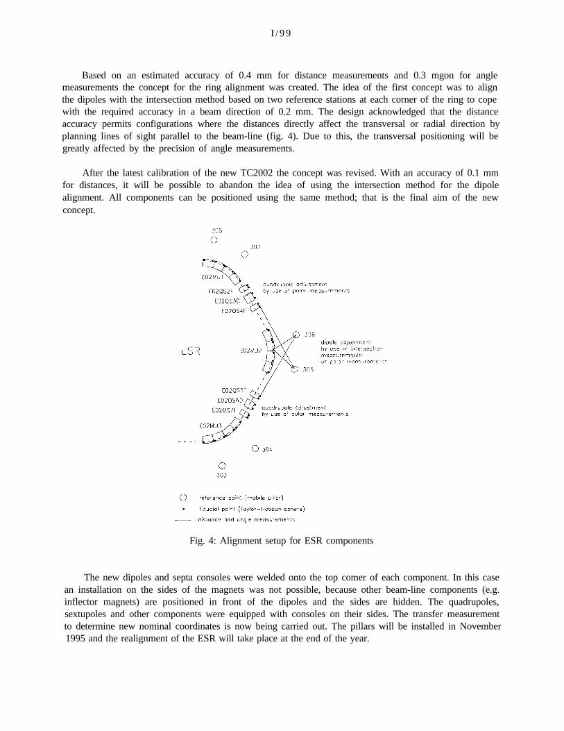
Based on an estimated accuracy of 0.4 mm for distance measurements and 0.3 mgon for anglemeasurements the concept for the ring alignment was created. The idea of the first concept was to alignthe dipoles with the intersection method based on two reference stations at each corner of the ring to copewith the required accuracy in a beam direction of 0.2 mm. The design acknowledged that the distanceaccuracy permits configurations where the distances directly affect the transversal or radial direction byplanning lines of sight parallel to the beam-line (fig. 4). Due to this, the transversal positioning will begreatly affected by the precision of angle measurements.
After the latest calibration of the new TC2002 the concept was revised. With an accuracy of 0.1 mmfor distances, it will be possible to abandon the idea of using the intersection method for the dipolealignment. All components can be positioned using the same method; that is the final aim of the newconcept.
Fig. 4: Alignment setup for ESR components
The new dipoles and septa consoles were welded onto the top comer of each component. In this casean installation on the sides of the magnets was not possible, because other beam-line components (e.g.inflector magnets) are positioned in front of the dipoles and the sides are hidden. The quadrupoles,sextupoles and other components were equipped with consoles on their sides. The transfer measurementto determine new nominal coordinates is now being carried out. The pillars will be installed in November1995 and the realignment of the ESR will take place at the end of the year.

I /100
7. CONCLUSION
The TASA Concept can be used for all alignments of the different GSI accelerators. For allaccelerators a special investigation was carried out to check if it is possible to position a new pillar systemand to install new consoles on the components. The free positioning of ficucial points makes it possible touse polar measurements for all components. This is an enormous advantage and a step forward foralignment procedures at GSI. Furthermore, use of a total station as opposed to the ECDS System meansthat one operator less is needed.
Although an older method existed and was practiced, the GSI has decided to abandon their alignmentconcept for a newer system. The time necessary for the alignment of an accelerator can be decreased byup to 50% using modem instrumentation and software.
REFERENCES
[1]
[2]
[3]
[4]
[5]
SCHMADEL, I. : Survey System for the SIS, SCIENTIFIC REPORT 1986, S.339
SCHMADEL, I. : Geodetic Survey and Component Alignment of the Experimental Storage CoolerRing ESR, Proc. 2nd. Intern. Workshop Accelerator Alignment (1990), S. 11-25.
PALUSZEK, H., SCHMADEL, I., WIRTH H.: TASA - A New Surveying and Alignment Concept,SCIENTIFIC REPORT 1992. S.444
SCHWARZ, W. : Die Justierung von Teilchenbeschleunigem, Allg. Verm.-Nachr., Karlsruhe 101(1990), S. 2-18
MAYOUD, MENANT, QUESNEL : Technological Evolution of Measurement Tools - Dilemmas,Illusions and Realities, Proceedings of the Second International Workshop on AcceleratorAlignment, DESY 1990