a new era in bracing for new zealand...specification guide a new era in bracing for new zealand...
TRANSCRIPT

SPECIFICATION GUIDE
www.modnbp.com
A new era in bracing for New Zealand
Advanced full performance tension only bracing system.


1
Contents
DONOBRACE bracing system 2
Dynamic testing 3
Points of difference 4
Design & dimensions 5
Product technical statement 8
Guidance for structural engineers 9
Worked example 10
Seismic design action coefficient 11
Test performance summary 14
Frequently asked questions 16
SPECIFICATION GUIDE
www.modnbp.com
SPECIFICATION GUIDE
2
DONOBRACE Bracing System
The DONOBRACE Bracing System is a roof and wall bracing system, developed specifically for lightweight structures. The system resists lateral winds and earthquake loads and has a registered patent: Registered Design (New Zealand 420398). Registered Patent (New Zealand 747701)
Why choose DONOBRACE?
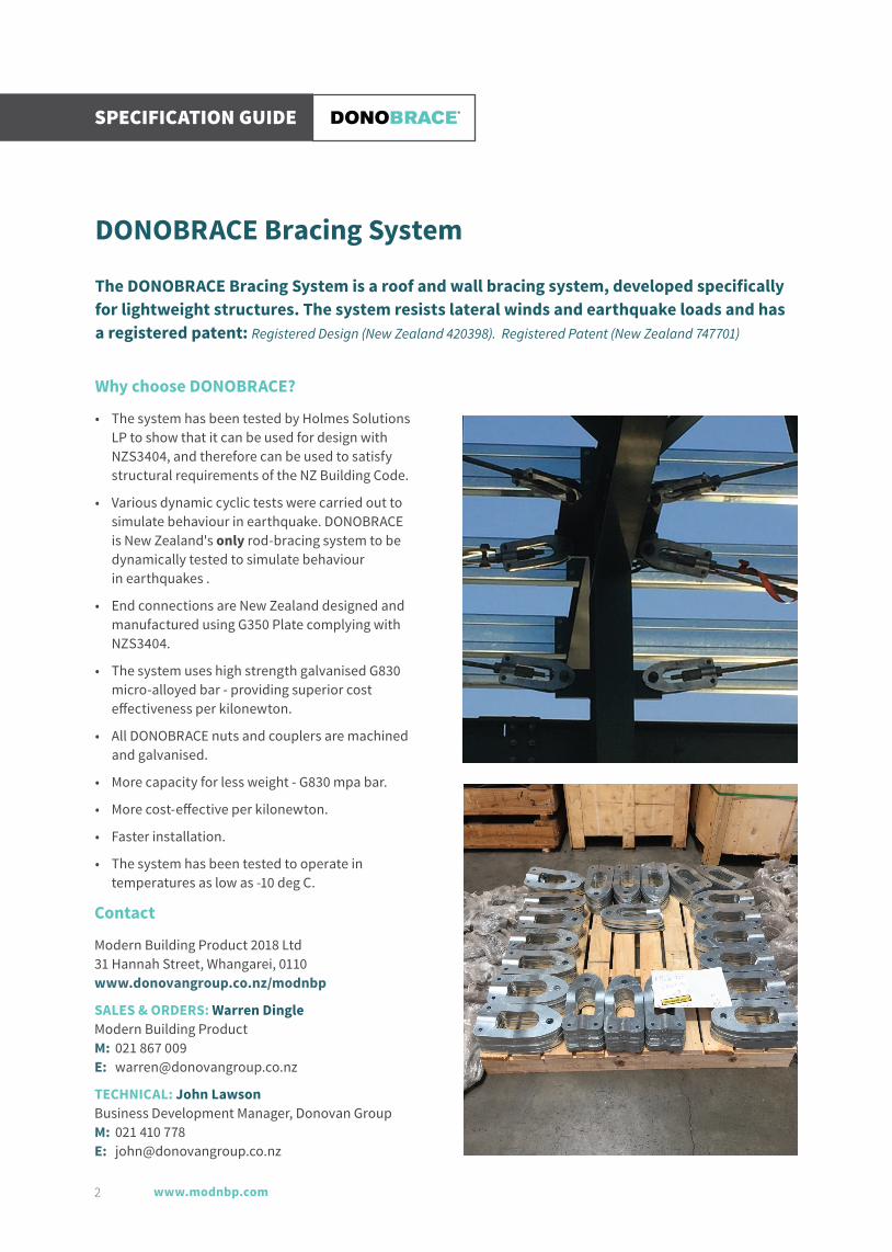
• The system has been tested by Holmes Solutions LP to show that it can be used for design with NZS3404, and therefore can be used to satisfy structural requirements of the NZ Building Code.
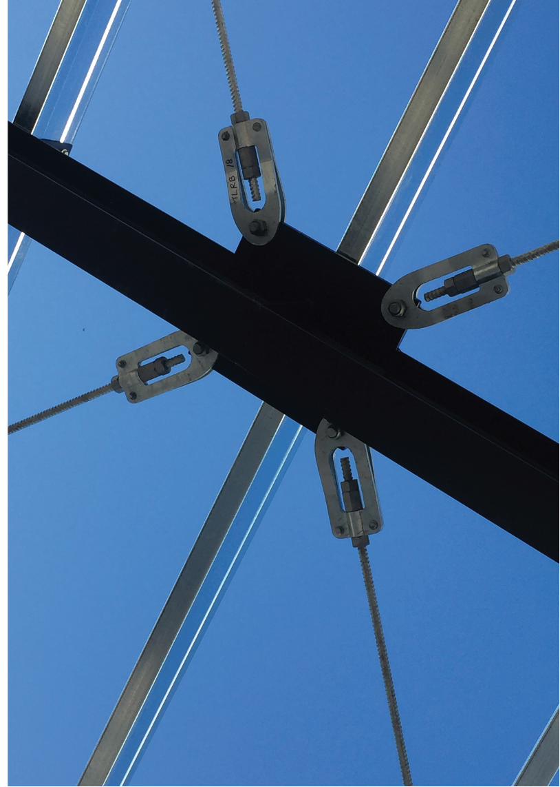
• Various dynamic cyclic tests were carried out to simulate behaviour in earthquake. DONOBRACE is New Zealand's only rod-bracing system to be dynamically tested to simulate behaviour in earthquakes .
• End connections are New Zealand designed and manufactured using G350 Plate complying with NZS3404.
• The system uses high strength galvanised G830 micro-alloyed bar - providing superior cost effectiveness per kilonewton.
• All DONOBRACE nuts and couplers are machined and galvanised.
• More capacity for less weight - G830 mpa bar.
• More cost-effective per kilonewton.
• Faster installation.
• The system has been tested to operate in temperatures as low as -10 deg C.
Contact
Modern Building Product 2018 Ltd 31 Hannah Street, Whangarei, 0110 www.donovangroup.co.nz/modnbp
SALES & ORDERS: Warren Dingle Modern Building Product M: 021 867 009 E: [email protected]
TECHNICAL: John Lawson Business Development Manager, Donovan Group M: 021 410 778 E: [email protected]
3
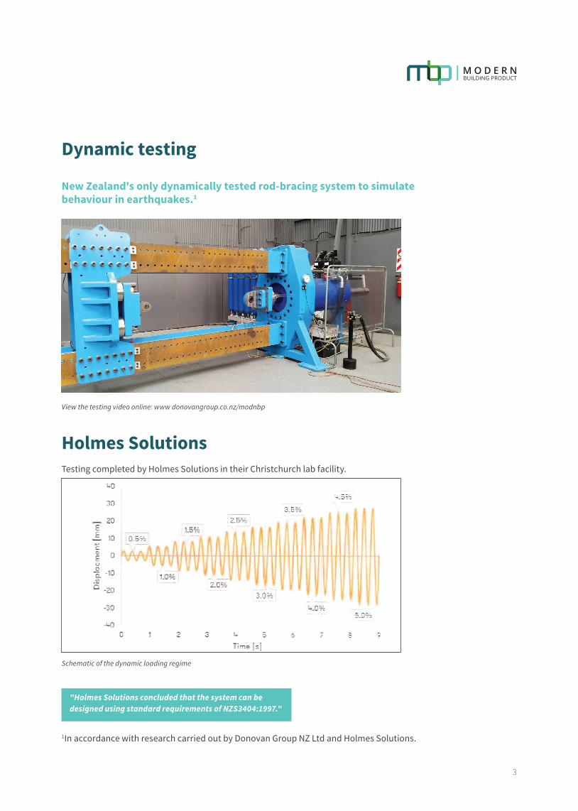
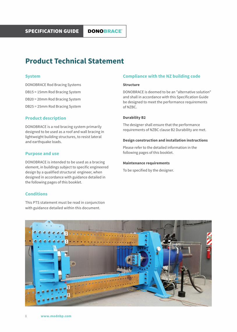
Dynamic testing
New Zealand's only dynamically tested rod-bracing system to simulate behaviour in earthquakes.1
View the testing video online: www donovangroup.co.nz/modnbp
Holmes SolutionsTesting completed by Holmes Solutions in their Christchurch lab facility.
Schematic of the dynamic loading regime
"Holmes Solutions concluded that the system can be designed using standard requirements of NZS3404:1997."
1In accordance with research carried out by Donovan Group NZ Ltd and Holmes Solutions.

www.modnbp.com
SPECIFICATION GUIDE
4
Points of diff erence
More cost eff ective per kN
DONOBRACE
Size kN*
15mm 132kN
20mm 235kN
25mm 367kN
Other brands
Size kN*
16mm 91kN
20mm 141kN
25mm 221kN
32mm 362kN
* Design yield strength = ø Nt (ø = 0.9)
More capacity – less weight
G830 threaded galvanised bar is tested to AS/NZS 1170.0 with G350 plate connections. This allows for greater kN capacity and less overall material weight.
Faster installation
Ends allow for less sophisticated coupling components i.e. no springs or split pins required.
Superior machining & galvanising quality
All coupling components are machined (not cast)and are galvanised using the mechanical galvanising process.

5
Design & dimensions
D815EC, DB20EC and DB25EC are Registered Designs with NZ Intellectual Property Off ice and has a registered patent.
Dimensional information DB15EC
Blocks, Revit & Archicad objects available online:www.donovangroup.co.nz/modnbp

www.modnbp.com
SPECIFICATION GUIDE
6
Dimensional information DB20EC Blocks, Revit & Archicad objects available online: www.donovangroup.co.nz/modnbp

7
Dimensional information DB25EC Blocks, Revit & Archicad objects available online: www.donovangroup.co.nz/modnbp
www.modnbp.com
SPECIFICATION GUIDE
8
Product Technical Statement
System
DONOBRACE Rod Bracing Systems
DB15 = 15mm Rod Bracing System
DB20 = 20mm Rod Bracing System
DB25 = 25mm Rod Bracing System
Product description
DONOBRACE is a rod bracing system primarily designed to be used as a roof and wall bracing in lightweight building structures, to resist lateral and earthquake loads.
Purpose and use
DONOBRACE is intended to be used as a bracing element, in buildings subject to specific engineered design by a qualified structural engineer, when designed in accordance with guidance detailed in the following pages of this booklet.
Conditions
This PTS statement must be read in conjunction with guidance detailed within this document.
Compliance with the NZ building code
Structure
DONOBRACE is deemed to be an "alternative solution" and shall in accordance with this Specification Guide be designed to meet the performance requirements of NZBC.
Durability B2
The designer shall ensure that the performance requirements of NZBC clause B2 Durability are met.
Design construction and installation instructions
Please refer to the detailed information in the following pages of this booklet.
Maintenance requirements
To be specified by the designer.

9
Guidance for structural engineers Holmes Solutions LP carried out testing, (including dynamic cyclic testing), to assess he performance of the DONOBRACE system against criteria from AS/ NZS1170 .0.
The Holmes Solutions assessment concluded that the system can be designed using standard requirements of NZS3404:1997 - (even though the bracing does not meet the material requirements of NZS3404 in a prescriptive sense).
System ductility
The testing report stated that a structural ductility factor of µ = 1 .25 is considered to be a maximum appropriate for design.
Design options:
1. Design as a Category 3 seismic-force resisting system (µ = 1.25 max) in accordance with NZS3404.
2. Design as a Category 4 seismic-force resisting system (µ = 1.00) in accordance with NZS3404.
System design capacity
DONOBRACE System Name
DonoBar Diameter (mm)
DonoBar Grade (MPa)
NZS34O4 Design Capacity øNt
DB15 DONOBRACE 15 830 132 kN
DB20 DONOBRACE 20 830 235 kN
DB25 DONOBRACE 25 830 367 kN
NOTE: Care should be taken in the design of gusset plates to ensure the high strength properties of the DONOBRACE system can be utilised.
System stiffness
Testing indicated that the stiffness of the systems were less than the elastic stiffness of the bare DonoBar only. This is due to slip and movement in the joints.
Recommendations: Use the most conservative value when modelling the stiffness of DONOBRACE.
Examples:
Bracing System Stiffness Reduction Factor
DB15 0.8
DB20 0.6
DB25 0.5
1. For load combinations where deflections are critical, use the reduced stiffness.
2. For load combinations where strength is critical, or for calculating the building's period of free vibration, use the full bar cross-sectional area

www.modnbp.com
SPECIFICATION GUIDE
10
Worked Example
The following worked example demonstrates the design of a tension-only bracing system using DONOBRACE components, to NZS1170.5:2004 and NZS3404:1997. It considers a typical warehouse structure which is designed to be a Nominally DuctileCategory 3 structure.
The decision to carry-out the seismic design to Category 3 requirements is based on acknowledgement of expected ductility demands given maximum drift s that could develop under Ultimate Limit State ground motions, and the relatively high yield drift of portal frames in the transverse direction, or the cross-braced bays in the longitudinal directions.
In the case of the cross-braced frames, with guidance from the DONOBRACE information booklet the recommended use of Category 3 or 4 design is a result of the extensive testing, both cyclic static and high-speed dynamic. This demonstrates that the DONOBRACE bars on their own have good ductile behaviour, while the complete brace system itself tends to produce hysteretic energy absorption more in-line with Nominally Ductile systems. This design decision is further reinforced when evaluating the lateral displacement at the eave-level that must develop in-order to induce strains over the length of the brace that exceed yield. Generally for these types of light-weight, short-period buildings the ULS displacement are not suff icient to induce significant ductility demands. Further discussion is provided in the example, to highlight the need for using design ductility values that are a reasonable representation of actual ductility demands.
The building
• Single storey portal frame warehouse consisting of seven portal frames spaced at 7.5m intervals. These provide the transverse lateral-force resisting system of the building.
• The longitudinal lateral-force resisting system of the building is provided by 4 tension-only cross braced bays, evenly distributed on each side of the building.
• Located near Christchurch central city, on Soil Class D ground.
• P-Delta eff ect are assumed not to be significant.
• The design described here considers lateral load in the longitudinal direction only to demonstrate the design decisions for the bracing system.
11
Seismic design action coeff icient – Ultimate Limit State
To NZS1170.5 with:
• Z = 0.3 for Christchurch
• Soil Class D
• Importance Level 2 with a 50-year design life R = 1.0
• Near-fault factor N(T,D) = 1.0
• Period T ≤ 0.4s. A value of 0.4 seconds is used here to demonstrate aspects of evaluating design ductility.
• µ = 1.25
The horizontal elastic hazard spectrum is determined following NZS1170.5 procedures per Section 3.1.1:
C(T) = Ch (T)ZRN(T,D)
The design base shear coeff icient is determined from section 5.2.1 for the Equivalent Static Method:
Cd (T1 ) = C(T1 ) Sp
k�
Where Sp = 0.9 (following NZS3404 Section 12.2.2.1) and kµ = 1.14, resulting in Cd = 0.71.
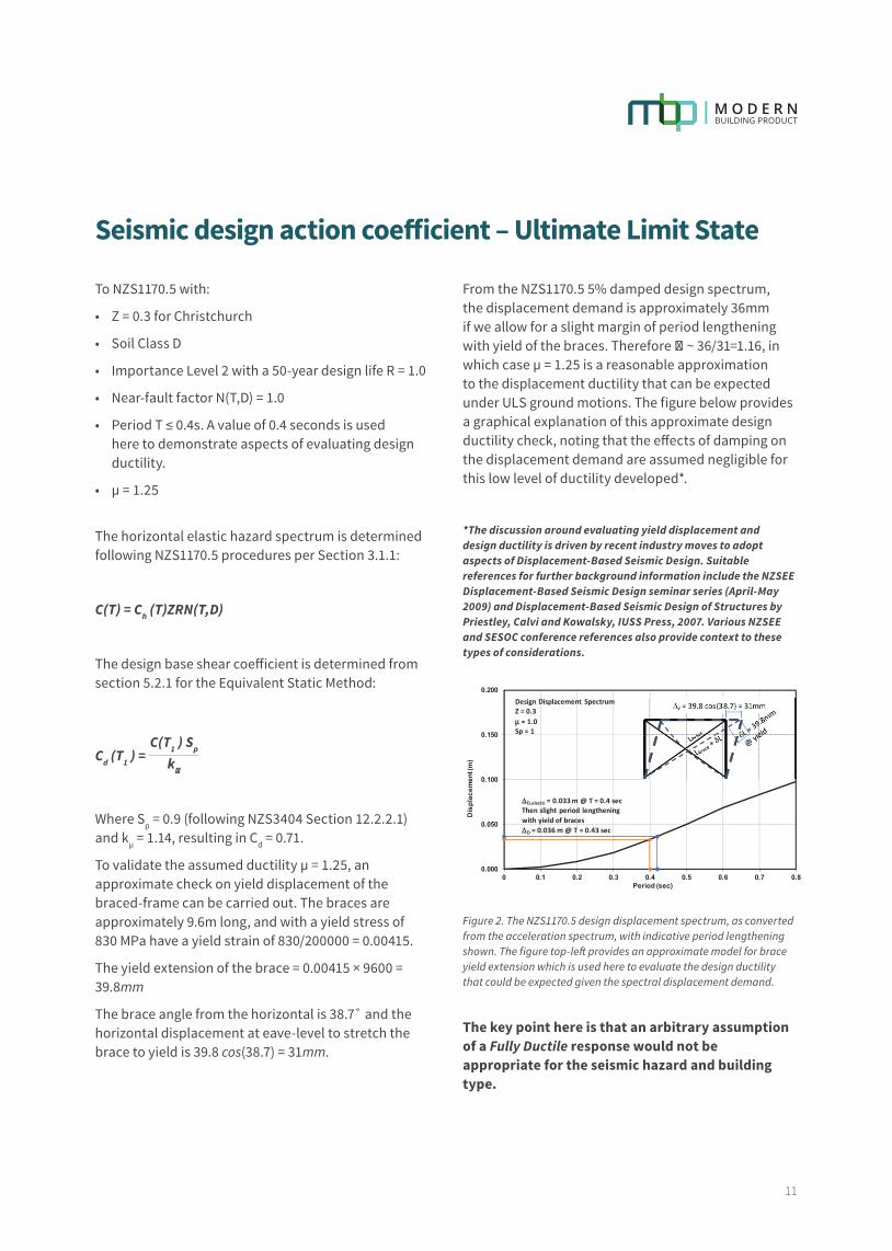
To validate the assumed ductility µ = 1.25, an approximate check on yield displacement of the braced-frame can be carried out. The braces are approximately 9.6m long, and with a yield stress of 830 MPa have a yield strain of 830/200000 = 0.00415.
The yield extension of the brace = 0.00415 × 9600 = 39.8mm
The brace angle from the horizontal is 38.7˚ and the horizontal displacement at eave-level to stretch the brace to yield is 39.8 cos(38.7) = 31mm.
From the NZS1170.5 5% damped design spectrum, the displacement demand is approximately 36mm if we allow for a slight margin of period lengthening with yield of the braces. Therefore β ~ 36/31=1.16, in which case µ = 1.25 is a reasonable approximation to the displacement ductility that can be expected under ULS ground motions. The figure below provides a graphical explanation of this approximate design ductility check, noting that the eff ects of damping on the displacement demand are assumed negligible for this low level of ductility developed*.
*The discussion around evaluating yield displacement and design ductility is driven by recent industry moves to adopt aspects of Displacement-Based Seismic Design. Suitable references for further background information include the NZSEE Displacement-Based Seismic Design seminar series (April-May 2009) and Displacement-Based Seismic Design of Structures by Priestley, Calvi and Kowalsky, IUSS Press, 2007. Various NZSEE and SESOC conference references also provide context to these types of considerations.
Figure 2. The NZS1170.5 design displacement spectrum, as converted from the acceleration spectrum, with indicative period lengthening shown. The figure top-left provides an approximate model for brace yield extension which is used here to evaluate the design ductility that could be expected given the spectral displacement demand.
The key point here is that an arbitrary assumption of a Fully Ductile response would not be appropriate for the seismic hazard and building type.
0.000
0.050
0.100
0.150
0.200
0 0.1 0.2 0.3 0.4 0.5 0.6 0.7 0.8
Dis
plac
emen
t (m
)
Period (sec)
DesignDisplacement SpectrumZ= 0.3µ =1.0Sp=1
DD,elastic =0.033m@T=0.4secThenslightperiod lengtheningwithyieldofbracesDD =0.036m@T=0.43sec
www.modnbp.com
SPECIFICATION GUIDE
12
Seismic load
Side wall Area = 45 × 6 = 270m² End wall Area = 20 × 6 + (0.5 × 20 × 1.5) = 135m² Roof Area = 45 × ( √10² + 1.5² ) × 2 = 910m²
Taking a lightweight construction for the roof and walls of 0.5kPa
Building Weight = (910 × 0.5) + (2 × (270 + 135) × 0.5) = 860kN Seismic Base Shear = 0.71 × 860 = 611kN or 153kN per braced bay
Wind load
To NZS1170.2 on a terrain category 2.5 site.
VR,500= 45ms–¹ (Table 3.1) Considering all directions then Md = 1.0
With z = 7.5m
Mz,cat = 0.89 (Table 4.1)
MS = 1.0 (Table 4.3)
Mh = 1.0
Vdes = Vsit,β = VRMd(Mz,catMs Mh ) = 40 ms–¹ (NZS1170.2 Eq 2.2)
Cpi = – 0.3 (Table 5.1 A)
For the windward end wall Cpe = 0.7 (Table 5.2 A)
For the leeward end wall Cpe = –0.5 (Table 5.2 A)
Force on windward end wall
F = (0.5βair ) V²desCfigCdyn = 0.5 × 1.2 × 40² × (0.7–(–0.3)) × 1.0 = 129 kN (Eq 2.5(2))
Force on Leeward end wall
F = (0.5βair ) V²desCfigCdyn = 0.5 × 1.2 × 40² × (–0.5– (-0.3)) × 1.0 = –26 kN
Therefore ∑ F = 129– (–26) = 155 kN
The total wind load is less then the seismic base shear. Seismic case will govern and will be used for the remainder of these calculations.
13
Brace forces
The braces are inclined at 39° therefore
Nt = = 197kN153
cos 39
The system is a Category 3 tension braced CBF and therefore to NZS3404 Clause 12.12.6.3.2 for ULS:
Cs = 1.1
Nt* = 197 × 1.1 = 216kN
From the DONOBRACE product literature a 20mm diameter DB20 has a capacity of
ØNt = 235kN
Checking the slenderness of the brace element shows it exceeds 120 and meets the requirements of Cl 12.12.6.1.
Note - If Category 4 design was used with Sp = 0.9 (following NZS3404 Section 12.2.2.1) this would result in:
Cd = 0.81
Cs = 1.0
Nt* = = 224kN per brace174kNcos 39
20mm diameter DB20 with ØNt = 235kN is required
Therefore even with the change from Category 3 to Category 4, the bracing sizing does not change in this case. This is a scenario that design engineers often find with tension-only braced frames where the combination of Sp and Cs approximately cancel one-another out, often meaning that Category 4 design is a reasonable approach to achieving a robust seismic design.
Connection design
Capacity design, per Cl 12.2.7, is used to ensure that the brace is the weakest point in the design. For a Category 3 system the maximum overstrength factor in NZS3404 Table 12.2.8(1) is ØOMS = 1.30. However tensile testing of the DONOBRACE bars from various batches has shown that Fu ⁄ Fy tends to vary from 1.25 to 1.4. This being the case, it is recommended that connection design forces are set equal to the full elastic design forces, derived with Sp = 1.0, following guidance of NZS 3404 Cl. 12.9.1.2.2(2) for both Category 3 and 4 structures. This approach covers the potential range of ØOMS for both short period (< 0.4 seconds) and long period (> 1.0 seconds) structures.
In this example the fully elastic design base shear coefficient Cd = 0.9.
NOMS = = 249 kN for each brace connection(0.9 x 860)/4
cos 39
Note that this is an effective ØOMS=1.26 for the Category 3 design case.
The connection cleat can now be designed to the Steel Construction New Zealand Steel Advisor CON1302 guidelines for a tension force of 249kN. A worked example and issue relating to cleat design are covered with their documentation.
Serviceability limit state
The SLS1 requirements are also evaluated based on the requirements of AS/NZS1170.0:2002 and NZS1170.5:2004. The DONOBRACE product information provides guidance on brace effective stiffness, which incorporates observed characteristics from the dynamic testing completed by Holmes Solutions LP. This can readily be allowed for in the seismic analysis by applying the reduction factor to the brace area.
The resulting seismic design values are Cd = 0.16 and Base Shear = 138kN. This base shear would then be applied to the model to confirm SLS1 displacements are suitably low.
www.modnbp.com
SPECIFICATION GUIDE
14
Level 2, 254 Montreal StreetChristchurch Central 8013
PO Box 6718Upper Riccarton, Christchurch 8442
holmessolutions.com
114211 RP 0516 v2.1 Page 1 of 2Australia Netherlands New Zealand USA
Australia Netherlands New Zealand USA
18 September 2017
Donovan Group NZ LtdAttention: Brett Donovan/Kerry McCullumSubject: RE: Summary of Donobrace Test Results
Dear Brett/Kerry,
The following summary provides background and an overall comparison for the 15mm, 20mm and 25mmdiameter Donobrace systems tested and reported by Holmes Solutions LP.
Donobrace System – Test Performance Summary
Table 1: Summary of stiffness properties
Donobrace diameter(mm)
Elastic stiffness(L = 3600 mm)
Effective stiffness Stiffness Reductionfactor
NZS3404:1997Member Category
Cl. 12.2.5
[kN/mm] [kN/mm]
15 mm 9.8 8 0.82 3, 4
20 mm 17.4 11 0.63 3, 4
25 mm 27.0 14 0.52 3, 4
Holmes Solutions was commissioned by Donovan Group Ltd to test the 15mm, 20mm and 25mm Donobracesystems. It is understood that the brace system is to be used in lightweight structures as part of the lateral-force resisting system. Review of the Donobrace system has identified that it does not meet the prescriptiverequirements of the New Zealand Steel Structures Standard (NZS 3404:1997), and thus Donovan Groupmust prove their product meets the New Zealand Building Code through special study as described inAS/NZS 1170 Structural Design Actions.
AS/NZS 1170.0:2002 Appendix A provides guidance on special studies and recommends their use to“establish information or methods for design”. The Appendix recommends testing as an appropriate form ofspecial study and cites the method provided in AS/NZS 1170.0:2002 Appendix B. AS/NZS 1170.0:2002Appendix B specifically states that testing can be used where “more accurate information is required foruse in structural design” and “specific design parameters are not included in the relevant Standard”. In thiscase the relevant Standard is NZS 3404:1997. Therefore this Appendix was used to establish the compliancepathway to the New Zealand Building Code, rather than the specific clause requirements of NZS 3404. Thepurpose of this testing is to provide evidence of the brace system performance and the findings from thetesting are expected to be made available to the engineering community.
For each of the brace diameters, four specimens were subjected to 20 high-stress cycles, achieving 90% oftheir yield strength. Following this quasi-static testing, the same specimens were then subjected to fourcycles targeting yield displacement and another four cycles targeting four times yield displacement. Allspecimens maintained tensile capacity, achieving extension displacements to four-times yield withoutstrength loss. Slip was observed in the connections that resulted in the brace system having a reducedeffective stiffness. The majority of the slip occurred in the first set of high-stress testing.

15
114211 RP 0516 v2.1 Page 2 of 2
Following quasi-static testing, another five specimens (of each brace diameter) were subjected to dynamic testing. Incrementally increasing displacment demands up to a maximum of three cycles at 5% equivalent storey drift (ESD). All specimens maintained tensile strength throughout the dynamic actions over the entire range of drift levels and no significant strength loss was observed. In all cases the stiffness of the brace system was found to be less than the calculated elastic stiffness of the individual Donobar brace element. This is attributed to thread slip and movement in the joints of the system, but was demonstrated through the testing to not be detrimental to overall system performance.
Interpretation of the test results indicate that when the Donobrace is used in a structure as a seismic lateral resisting member, performance of the system has a limited amount of energy dissipation, and as such a structural ductility factor μ = 1.25 (commensurate with Category 3 members in NZS3404:1997) is considered to be a maximum appropriate for design. In addition, care should be taken in the design of the gusset plates to account for the Grade 830 bar strength.
Regards,
Didier PettingaSENIOR ENGINEER

www.modnbp.com
SPECIFICATION GUIDE
16
Frequently Asked Questions Q. How does the system perform during testing?
A. Report Available upon request - Summary page 14.
Q. What is the minimum yield of the bar/nuts/couplers?
A. Values for DB15, DB20, DB25 - 830mpa.
Q. Do you have a manufacturers recommended installation guide?
A. See the DONOBRACE Installation Guide at donovangroup.co.nz/modnbp.
Q. Are the bolts part of the dynamically tested bracing system?
A. Yes
Q. How should the bolts be tightened?
A. The bolts shall be tightened to "Snug Tight" in accordance with AS/NZS 5231.
Q. What is the max/min thickness of plate that can be used for the cleat?
A. The bracing end connection has been manufactured to suit the connection plate sizes shown in the Dimensional Information. (One plate size larger and one plate size lower may be used). N.B. The connection plates need to be specifically designed by an engineer.
Q. Do we have a specification for painting the bars to improve durability?
A. We suggest you contact your preferred coating supplier. We have a specification from our supplier which we can provided if required.
Q. What is the purpose of the nyloc nut? Can we use this system with a standard nut or double nut instead?
A. The nyloc nut is used to prevent the nut coming loose during dynamic loading.
Q. How are the bars made? Rolled thread?
A. The bars are micro-alloyed with a rolled thread. The nuts and connectors have a machined thread.
Even though the material used in the braces sits outside of NZS 3404 standard specification for seismic-resisting elements, the behaviour of the material and brace system has been reviewed (via testing) for its equivalent performance. As such, standard design values as specified in NZS 3404 are considered appropriate for the DONOBRACE system.
17

0800 002 542
www.modnbp.com