a methodology to enable automatic 3d routing of aircraft ... · section 3.1 provides a description...
TRANSCRIPT
ORIGINAL PAPER
A methodology to enable automatic 3D routing of aircraftElectrical Wiring Interconnection System
Z. Zhu1 • G. La Rocca1 • M. J. L. van Tooren2
Received: 29 February 2016 / Revised: 8 December 2016 /Accepted: 20 February 2017 / Published online: 10 March 2017
� The Author(s) 2017. This article is published with open access at Springerlink.com
Abstract Harness 3D routing is one of the most challenging
steps in the design of aircraft Electrical Wiring Interconnec-
tion System (EWIS). This is due not only to the intrinsic
complexity of the EWIS, but also to the increasing number of
applying design constraints and its dependency on any change
in the designof the airframeand installed systems.The current
routing process employed by EWISdesign is largely based on
the manual work of expert engineers, partially supported by
conventional CAD systems. As a result, the routing process is
quite inefficient, error prone and unable to deliver optimal
solutions. Although many harness components are selected
from catalogues and the design process is largely repetitive
and rule based, it has been found that none or very limited
automation solutions, which can significantly decrease the
workload of engineers and increase their efficiency, are cur-
rently available. In this paper, an innovative approach is
proposed to solve the 3D routing automation as an optimiza-
tion problem. Knowledge Based Engineering (KBE) and
optimization methods are proposed to achieve minimum cost
routing solutions that satisfy all relevant design rules and
constraints. The proposed solution is scalable in terms of
constraints, can be deployed on any type of routing environ-
ment, and, thanks to the achieved level of automation, able to
reduce the process lead time drastically. The basic idea is to
achieve optimal EWIS routing solutions by optimizing the
position of the harnesses clamping points, which are used as
way-points to route the harnesses inside the aircraft digital
mock-up. The challenge to solve this optimization problem is
that the number and initial value of design variables, namely
the number and position of clamping points, are not known a
priori. To handle this challenge, a two-step, hybrid opti-
mization strategy has been devised. The first step, called Ini-
tialization, uses a road map based path finding method to
generate a preliminary harness definition, including the
required number and preliminary position of its clamping
points. The second step, called Refinement, uses a conven-
tional optimizationmethod tomove the position of the clamps
and refine the preliminary harness definition aiming for the
minimum cost and the satisfaction of all the design con-
straints. This approach has been implemented into a KBE
application connected with a commercial optimization pack-
age and tested on several routing cases. The results demon-
strate that the proposedmethod is capable of handling cases of
representative geometric complexity and design constraints
and delivering proper 3D harness models in full automation.
Keywords EWIS � Wire harness � 3D routing automation �KBE � MDO
1 Design challenges in the developmentof the aircraft Electrical Wiring InterconnectionSystems
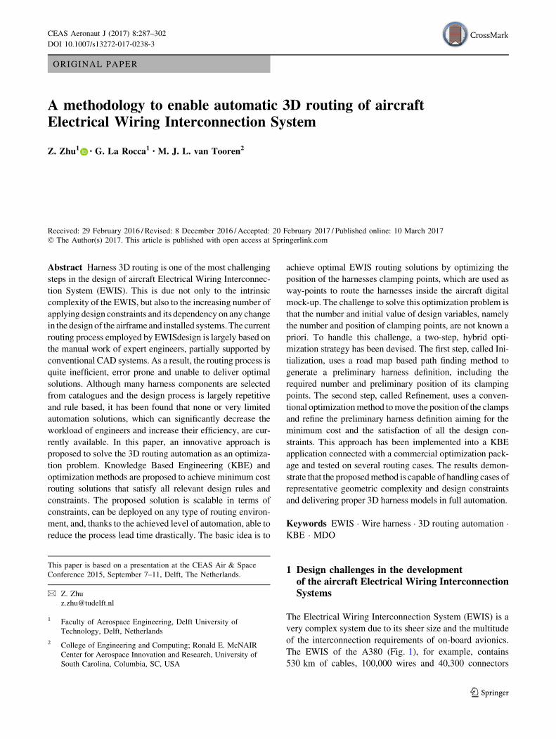
The Electrical Wiring Interconnection System (EWIS) is a
very complex system due to its sheer size and the multitude
of the interconnection requirements of on-board avionics.
The EWIS of the A380 (Fig. 1), for example, contains
530 km of cables, 100,000 wires and 40,300 connectors
This paper is based on a presentation at the CEAS Air & Space
Conference 2015, September 7–11, Delft, The Netherlands.
& Z. Zhu
1 Faculty of Aerospace Engineering, Delft University of
Technology, Delft, Netherlands
2 College of Engineering and Computing; Ronald E. McNAIR
Center for Aerospace Innovation and Research, University of
South Carolina, Columbia, SC, USA
123
CEAS Aeronaut J (2017) 8:287–302
DOI 10.1007/s13272-017-0238-3
[2]. Although the wiring volume tends to reduce thanks to
the implementation of data-buses (e.g., the Boeing 737NG
has several kilometres less wiring compared to its prede-
cessor), the complexity of the EWIS is deemed to further
increase in new generation More-Electrical-Aircraft
(MEA) and Full-Electrical-Aircraft (FEA) [3]. Significant
advances in the design method of such a system are nec-
essary, not only to efficiently address the growing amount
of electronic systems to be interconnected, but also to
comply with the growing amount of safety regulations
stipulated by Certification Authorities concerning reliabil-
ity and redundancy [4].
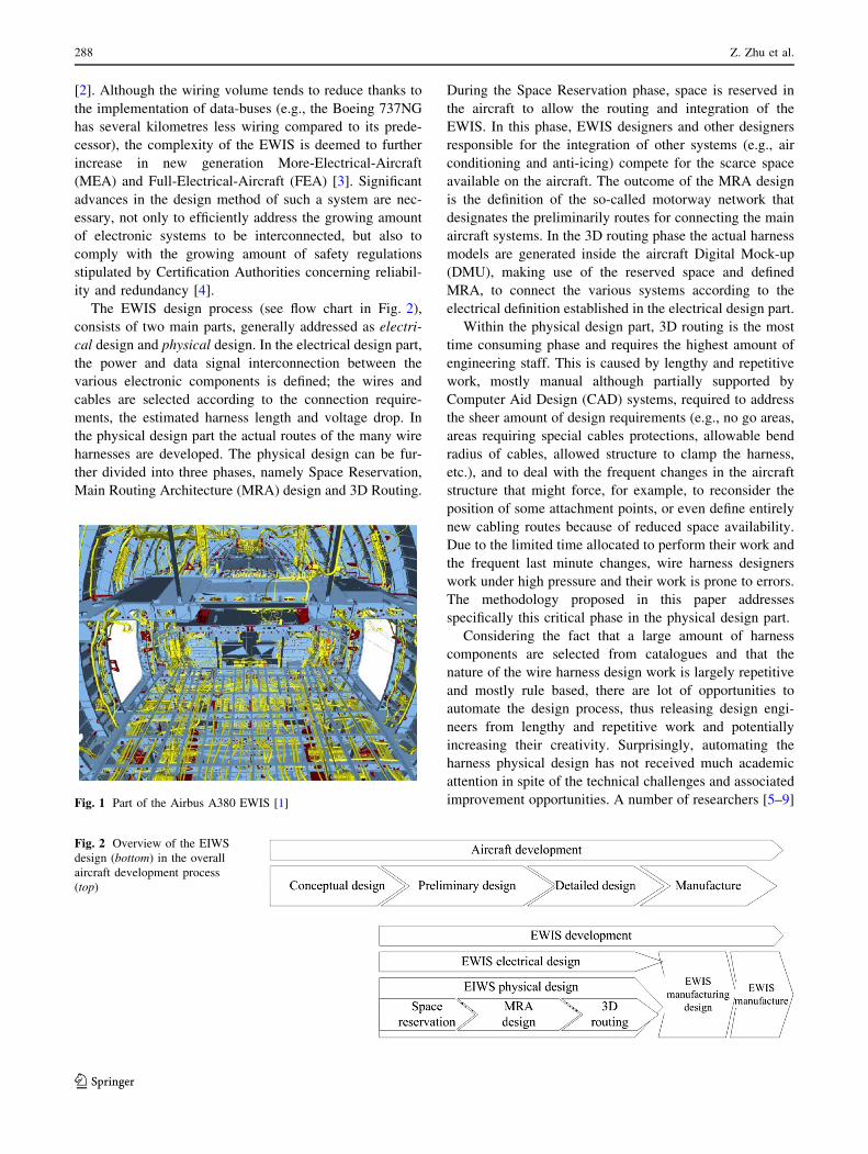
The EWIS design process (see flow chart in Fig. 2),
consists of two main parts, generally addressed as electri-
cal design and physical design. In the electrical design part,
the power and data signal interconnection between the
various electronic components is defined; the wires and
cables are selected according to the connection require-
ments, the estimated harness length and voltage drop. In
the physical design part the actual routes of the many wire
harnesses are developed. The physical design can be fur-
ther divided into three phases, namely Space Reservation,
Main Routing Architecture (MRA) design and 3D Routing.
During the Space Reservation phase, space is reserved in
the aircraft to allow the routing and integration of the
EWIS. In this phase, EWIS designers and other designers
responsible for the integration of other systems (e.g., air
conditioning and anti-icing) compete for the scarce space
available on the aircraft. The outcome of the MRA design
is the definition of the so-called motorway network that
designates the preliminarily routes for connecting the main
aircraft systems. In the 3D routing phase the actual harness
models are generated inside the aircraft Digital Mock-up
(DMU), making use of the reserved space and defined
MRA, to connect the various systems according to the
electrical definition established in the electrical design part.
Within the physical design part, 3D routing is the most
time consuming phase and requires the highest amount of
engineering staff. This is caused by lengthy and repetitive
work, mostly manual although partially supported by
Computer Aid Design (CAD) systems, required to address
the sheer amount of design requirements (e.g., no go areas,
areas requiring special cables protections, allowable bend
radius of cables, allowed structure to clamp the harness,
etc.), and to deal with the frequent changes in the aircraft
structure that might force, for example, to reconsider the
position of some attachment points, or even define entirely
new cabling routes because of reduced space availability.
Due to the limited time allocated to perform their work and
the frequent last minute changes, wire harness designers
work under high pressure and their work is prone to errors.
The methodology proposed in this paper addresses
specifically this critical phase in the physical design part.
Considering the fact that a large amount of harness
components are selected from catalogues and that the
nature of the wire harness design work is largely repetitive
and mostly rule based, there are lot of opportunities to
automate the design process, thus releasing design engi-
neers from lengthy and repetitive work and potentially
increasing their creativity. Surprisingly, automating the
harness physical design has not received much academic
attention in spite of the technical challenges and associated
improvement opportunities. A number of researchers [5–9]Fig. 1 Part of the Airbus A380 EWIS [1]
Fig. 2 Overview of the EIWS
design (bottom) in the overall
aircraft development process
(top)
288 Z. Zhu et al.
123
have focused on the automation of EWIS design. However,
none or very limited solutions to automate the 3D routing
part of the EWIS design process have been found. Also the
current leading Mechanical CAD (MCAD) tools used in
industry are not able to generate wire harness 3D models
automatically and still demand a lot of manual work by
expert designers.
2 Knowledge Based Engineeringand Multidisciplinary Design Optimizationto automate 3D routing of wire harnesses
This paper proposes a novel methodology to address the
3D routing challenges discussed in Sect. 1. In particular the
proposed methodology aims at the following two main
objectives:
1. Automate the generation of the 3D wire harness
models, by capturing and systematically reusing the
experts’ knowledge;
2. Automatically update wire harness models when
changes occur, either in the routing environment, or
in the electrical design of the EWIS.
The proposed approach is based on the hypothesis that
solving the 3D routing problem is equivalent to solving an
optimization problem. In this case, the objective function to
minimize represents the cost function that accounts for
both the total cost of the wire harness and the cost of the
protection layers and support components required to route
the harness in area with harsh environment (heat, vibration,
etc.). The design variables represent the position of the
various clamping points where the cables are fixed to the
aircraft structure and which, in practice, are used by the
design engineers to control the position and shape of har-
nesses. The various design rules, such as minimum allowed
bend radius, maximum distance between contiguous
clamping points, and minimum distance between cable and
support structure, are formulated as constraint functions for
the optimization problem.
The technical implementation of the proposed approach
is built on a combination of Knowledge Based Engineering
(KBE) [10] and Multidisciplinary Design Optimization
(MDO) [11] technologies. KBE technology is exploited to
capture the typical rule-based approach of wire harness
design and to enable the automation of all the geometric
manipulations and checks required to perform the routing
task. MDO is used to systematically explore the large
design space provided by the 3D routing problem, to dis-
cover the minimum cost solution that complies with the
multitude of design constraints.
Section 3 of this paper provides an overview of the
EWIS architecture and the main design rules involved in
wire harness routing. Sections 4, 5 and 6 describe the
actual definition of the optimization problem and its tech-
nical implementation. In Sect. 7, examples are provided to
demonstrate the capability of the proposed approach to
meet the two objectives. Conclusions and recommenda-
tions are given in Sect. 8.
3 Description of aircraft EWIS and 3D routingrules
Section 3.1 provides a description of the aircraft EWIS and
clarifies the focus area of the proposed methodology.
Section 3.2 details the design rules and checks to be
applied during the 3D routing. Both subsections introduce
the terminology that is then used in the formulation of the
optimization problem.
3.1 Description of the aircraft EIWS
The aircraft EWIS propagates through almost every part of
the airframe and the engines. To facilitate manufacturing
and installation, it is designed as a set of separate har-
nesses, which, during assembly, are connected at the so
called production-break points. The way the EWIS is split
into different sets of harnesses strongly depends on the
aircraft zones where the EWIS is routed. These zones are
called wiring zones and differ from each other because of
their environmental conditions, such as heat, vibration, and
moisture. As consequence, each wiring zone may demand
some different design rules. In practice, each wiring zone is
independent from the others for what concerns the design
and installation process. The earlier mentioned production-
breaks represent the only interface between the adjacent
zones. The production-breaks are predefined and generally
not modified during the 3D routing process.
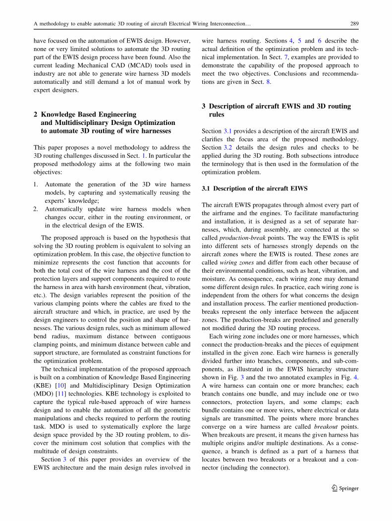
Each wiring zone includes one or more harnesses, which
connect the production-breaks and the pieces of equipment
installed in the given zone. Each wire harness is generally
divided further into branches, components, and sub-com-
ponents, as illustrated in the EWIS hierarchy structure
shown in Fig. 3 and the two annotated examples in Fig. 4.
A wire harness can contain one or more branches; each
branch contains one bundle, and may include one or two
connectors, protection layers, and some clamps; each
bundle contains one or more wires, where electrical or data
signals are transmitted. The points where more branches
converge on a wire harness are called breakout points.
When breakouts are present, it means the given harness has
multiple origins and/or multiple destinations. As a conse-
quence, a branch is defined as a part of a harness that
locates between two breakouts or a breakout and a con-
nector (including the connector).
A methodology to enable automatic 3D routing of aircraft Electrical Wiring Interconnection… 289
123
3.2 3D routing rules
The 3D routing process is constrained by many design
rules. Some of these design rules are described in the
design specifications issued by the authorities to guarantee
the safety of the aircraft; others have been developed by
wire harness manufactures themselves, on the basis of
experience and best practice. A subset of these rules has
been selected and implemented in this work. These include,
for example, the rules to check allowed bending radii and
geometry collision, as well as those for the definition of the
clamping system and routing in critical wiring zones, such
as in presence of heat sources or high flammability risk. All
these rules are discussed in some detail in the following
sub-sections.
It is important to note that the selected rule subset has
been selected in consultancy with EWIS manufactures and
consists of the most relevant ones, both in terms of the
frequency of application and complexity of implementa-
tion. This subset was deemed sufficient to demonstrate the
capability of the proposed approach, which, anyhow, was
developed to guarantee full scalability, as further discussed
in Sect. 6.
3.2.1 Minimum bend radius rule
A wire bundle or a cable must not be bent beyond its
allowed limits to avoid damage. The minimum allowed
bend radius of a wire bundle is determined by the product
of its diameter and allowed bend radius ratio, namely
1� Dbundle. Dbundle is the bundle diameter and 1 is the
allowed bend radius ratio, which mainly depends on the
bundle material. The principle to select the bend radius
ratio can be found in design specifications MIL-W-5088L
[12] and Aircraft EWIS Best Practices [13]. The bend
radius violation free of a bundle is represented by the
inequality rbendmin � 1� Dbundle, where rbendmin is the minimum
bend radius of the bundle measured at the bundle centre
curve. As mentioned in Sect. 2, KBE systems as the one
used in this work allow performing this kind of geometrical
check in a very efficient manner.
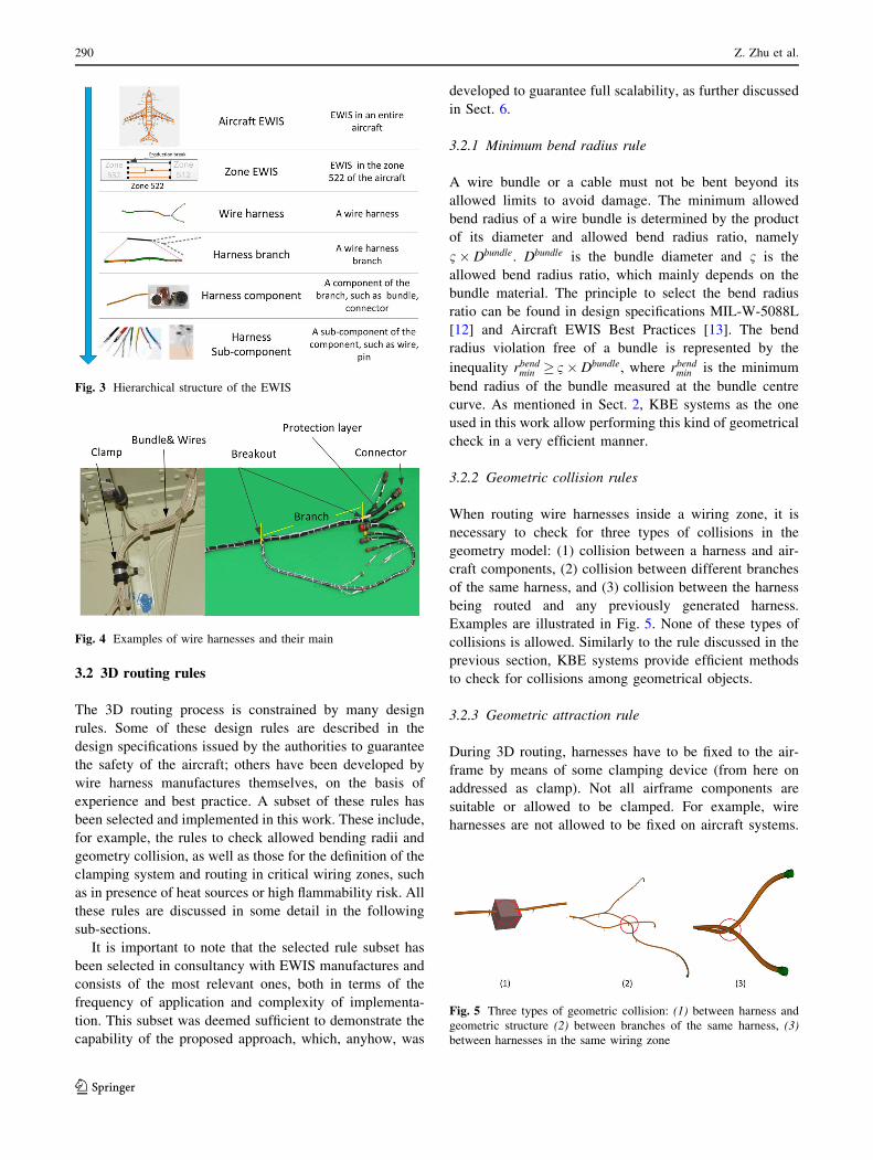
3.2.2 Geometric collision rules
When routing wire harnesses inside a wiring zone, it is
necessary to check for three types of collisions in the
geometry model: (1) collision between a harness and air-
craft components, (2) collision between different branches
of the same harness, and (3) collision between the harness
being routed and any previously generated harness.
Examples are illustrated in Fig. 5. None of these types of
collisions is allowed. Similarly to the rule discussed in the
previous section, KBE systems provide efficient methods
to check for collisions among geometrical objects.
3.2.3 Geometric attraction rule
During 3D routing, harnesses have to be fixed to the air-
frame by means of some clamping device (from here on
addressed as clamp). Not all airframe components are
suitable or allowed to be clamped. For example, wire
harnesses are not allowed to be fixed on aircraft systems.
Fig. 3 Hierarchical structure of the EWIS
Fig. 4 Examples of wire harnesses and their main
Fig. 5 Three types of geometric collision: (1) between harness and
geometric structure (2) between branches of the same harness, (3)
between harnesses in the same wiring zone
290 Z. Zhu et al.
123
Rules are necessary to guarantee only fixable structures
(i.e., the structure that allows harnesses to be fixed on) are
used for clamping. To minimize space occupation, as well
as the weight of the clamps, it is convenient to route har-
nesses in proximity of fixable structures. This is the so-
called geometric attraction rule. Also in this case, KBE
systems provide the necessary geometry analysis and
manipulation methods to support the implementation of
this rule.
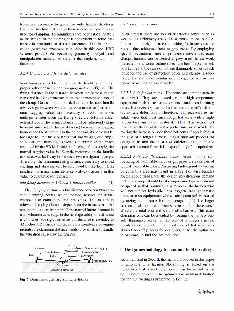
3.2.4 Clamping and fixing distance rules
Wire harnesses need to be fixed on the fixable structure at
proper values of fixing and clamping distance (Fig. 6). The
fixing distance is the distance between the harness centre
curve and its fixing structure, measured in correspondence of
the clamp. Due to the natural deflection, a harness bundle
always sags between two clamps. As a matter of fact, mini-
mum sagging values are necessary to avoid harnesses
undergo tension when the fixing structure deforms under
external loads. The fixing distance must be sufficiently large
to avoid any contact (hence abrasion) between the sagging
harness and the structure. On the other hand, it should not be
too large to limit the size (thus cost and weight) of clamps,
stand-off, and brackets, as well as to minimize the space
occupied by the EWIS. Inside the fuselage, for example, the
normal sagging value is 1/2 inch, measured on the bundle
centre curve, half way in between two contiguous clamps.
Therefore, the minimum fixing distance necessary to avoid
chaffing and abrasion can be calculated by the Eq. (1). In
practice, the actual fixing distance is always larger than this
value to guarantee some margin.
min fixing distance ¼ 1=2inchþ harness radius ð1Þ
The clamping distance is the distance between two adja-
cent clamping points, which include, besides the actual
clamps, also connectors and breakouts. The maximum
allowed clamping distance depends on the harness material
and the routing environment. For a normal harness routed in
a no-vibration zone (e.g., in the fuselage cabin) this distance
is 24 inches. For rigid harnesses this distance is extended to
42 inches [12]. Inside wings, in correspondence of engine
mounts, the clamping distance needs to be smaller to handle
the vibration caused by the engines.
3.2.5 Grey areas rules
In an aircraft, there are lots of hazardous zones, such as
wet, hot and vibratory areas. These zones are neither for-
bidden (i.e., black) nor free (i.e., white) for harnesses to be
routed, thus addressed here as grey areas. By employing
special precautions such as protection covers and extra
clamps, harness can be routed in grey areas. In the work
presented here, some routing rules have been implemented,
now limited to the cases of hot and flammable zones, which
influence the use of protection cover and clamps, respec-
tively. Extra rules of similar nature, e.g., for wet or cor-
rosive areas, can be easily added.
3.2.5.1 Rule for hot zones Hot zones are common areas in
an aircraft. They are located around high-temperature
equipment such as resistors, exhaust stacks, and heating
ducts. Harnesses exposed to high temperature suffer deteri-
oration and deformation. Therefore, it is necessary to ‘in-
sulate wires that must run through hot areas with a high-
temperature insulation material.’ [12]. The extra cost
incurred by the use of dedicated protection can be avoided by
routing the harness outside these hot zones if applicable, at
the cost of a longer harness. It is a trade-off process for
designers to find the most cost efficient solution. In the
approach presented here, it is responsibility of the optimizer.
3.2.5.2 Rule for flammable zones Areas in the sur-
rounding of flammable fluids or gas pipes are examples of
typical flammable zones. An arcing fault caused by broken
wires in this area may result in a fire. For wire bundles
routed above fluid lines, the design specifications demand
that ‘‘the clamps should be of compression type and should
be spaced so that, assuming a wire break, the broken wire
will not contact hydraulic lines, oxygen lines, pneumatic
lines, or other equipments whose subsequent failure caused
by arcing could cause further damage.’’ [13] The larger
amount of clamps that is necessary to route in these zones
affects the total cost and weight of a harness. This extra
clamping cost can be avoided by routing the harness out-
side flammable zones, at the cost of a longer harness.
Similarly to the earlier mentioned case of hot zone, it is
also a trade-off process for designers, or for the optimizer
in our case, to find the best solution.
4 Design methodology for automatic 3D routing
As anticipated in Sect. 2, the method proposed in this paper
to automate wire harness 3D routing is based on the
hypothesis that a routing problem can be solved as an
optimization problem. The optimization problem definition
for the 3D routing is presented in Eq. (2).
Structure
Maximum sagging
Fixing distance
Clamp
Harness
Clamping distance
ClearanceBundle radiusBundle lower
edge
Fig. 6 Definition of clamping and fixing distance
A methodology to enable automatic 3D routing of aircraft Electrical Wiring Interconnection… 291
123
min fxðxÞ
f ðxÞ ¼Xm
j¼1
fiðxÞ ¼Xm
j¼1
LjðxÞCojðxÞ
with respect to x
subject to CiðxÞ� 0
ð2Þ
The objective function is the harness cost function (e.g.,
in Euros), which is the summation of each branch cost fjðxÞdefined as the product of the harness branch length Lj and
branch cost coefficient Coj, namely the unit length cost of
the given branch. The cost coefficient Coj is the summation
of the following three sub-cost coefficients:
• Cob sub-cost coefficient of bundles. This depends on
the diameter of the bundle;
• Coc sub-cost coefficient of clamps. This depends on the
amount of clamps used to fix the given branch to the
airframe, where the amount of clamps results from the
application of the clamping distance and flammable
zone rules;
• Cop sub-cost coefficient of protections. This depends
on the amount and type of protecting layers used when
routing the given harness branch through hot areas (hot
zone rule application).
The cost in this object function includes the material
cost and a part of the installation cost (included in the
clamping cost). In practice, this function can include more
cost items, such as the manufacturing cost and a part of the
operation cost (i.e., fuel consumption caused by the harness
weight), using the cost calculation methods provided by
harness manufacturers.
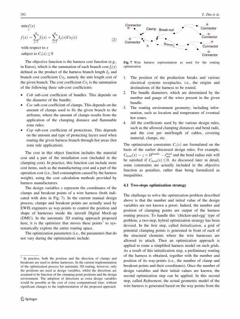
The design variables x represent the coordinates of the
clamps and breakout points of a wire harness (both indi-
cated with dots in Fig. 7). In the current manual design
process, clamps and breakout points are actually used by
EWIS engineers as way-points to control the position and
shape of harnesses inside the aircraft Digital Mock-up
(DMU). In the automatic 3D routing approach proposed
here, it is the optimizer that moves these points1 to sys-
tematically explore the entire routing space.
The optimization parameters (i.e., the parameters that do
not vary during the optimization) include:
1. The position of the production breaks and various
electrical systems receptacles, i.e., the origins and
destinations of the harness to be routed.
2. The bundle diameters, which are determined by the
number and gauge of the wires present in the given
bundle.
3. The routing environment geometry, including infor-
mation, such as location and temperature of eventual
hot zones.
4. All the coefficients used by the various design rules,
such as the allowed clamping distances and bend radii,
and the cost per unit/length of cables, covering
material, clamps, etc.
The optimization constraints CiðxÞ are formulated on the
basis of the earlier discussed design rules. For example,
CbendðxÞ ¼ 1� Dbundle � rbendmin and the bend radius rule will
be satisfied if CbendðxÞ� 0. As discussed later in detail,
some constraints are actually included in the objective
function as penalties, rather than being formalized as
inequalities.
4.1 Two-steps optimization strategy
The challenge to solve the optimization problem described
above is that the number and initial value of the design
variables are not known a priori. Indeed, the number and
position of clamping points are output of the harness
routing process. To handle this ‘chicken-and-egg’ type of
problem, a two-step, hybrid optimization strategy has been
devised. In the first step, called Initialization, a grid of
potential clamping points is generated in front of each of
the structural elements where the wire harnesses are
allowed to attach. Then an optimization approach is
applied to route a simplified harness model on such grids.
As a result of this initialization step, a preliminary routing
of the harness is obtained, together with the number and
position of its way-points (i.e., the number of clamp and
breakout points and their coordinates). Once the number of
design variables and their initial values are known, the
second optimization step can be applied. In this second
step, called Refinement, the actual geometric model of the
wire harness is generated based on the way-points from the
Fig. 7 Wire harness representation as used for the routing
optimization
1 In practice, both the position and the direction of clamps and
breakouts are used to define harnesses. In the current implementation
of the optimization process for automatic 3D routing, however, only
the positions are used as design variables, whilst the directions are
assumed to be function of the clamping point positions and the design
environment. The adoption of directions as extra design variables
would be possible at the cost of extra computational time, without
significant changes to the implementation of the proposed approach.
292 Z. Zhu et al.
123
Initialization, which are here varied by another optimizer to
minimize the harness cost objective function, while satis-
fying all the design constraints. These two steps will be
elaborated in Sects. 5 and 6, respectively.
4.2 KBE framework for hybrid optimization
KBE has been used to support the two-step optimization
process. A KBE application was developed using a com-
mercial KBE system, to take care of all the geometric
modelling and querying operations necessary 1) to com-
pute the state variables and objective function and 2) to
evaluate the constraints function during the various opti-
mization loops. In particular, the KBE application is taking
care of reading in the geometry of the aircraft (i.e., the
routing environment), generating the grids (see details in
Sect. 5.2) for the Initialization phase modelling the har-
nesses as lofted surfaces along b-splines curves, measuring
harness data such as bundle lengths and bend radii, and
checking for the violation of design rule such as geometric
collisions. The actual optimizations are performed by a
separate commercial optimization toolbox, linked to the
KBE application.
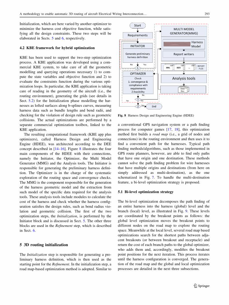
The resulting computational framework (KBE app plus
optimizers), called Harness Design and Engineering
Engine (HDEE), was architected according to the DEE
concept described in [14–16]. Figure 8 illustrates the four
main components of the HDEE with their connections,
namely the Initiator, the Optimizer, the Multi Model
Generator (MMG) and the Analysis tools. The Initiator is
responsible for generating the preliminary harness defini-
tion. The Optimizer is in the charge of the systematic
exploration of the routing space and convergence checks.
The MMG is the component responsible for the generation
of the harness geometric model and the extraction from
such model of the specific data required for the analysis
tools. These analysis tools include modules to calculate the
cost of the harness and check whether the harness config-
uration satisfies the design rules, such as bend radius vio-
lation and geometric collision. The first of the two
optimization steps, the Initialization, is performed by the
Initiator block and is discussed in Sect. 5. The other three
blocks are used in the Refinement step, which is described
in Sect. 6.
5 3D routing initialization
The Initialization step is responsible for generating a pre-
liminary harness definition, which is then used as the
starting point for the Refinement. In the initialization step, a
road map-based optimization method is adopted. Similar to
a conventional GPS navigation system or a path finding
process for computer games [17, 18], this optimization
method first builds a road map (i.e., a grid of nodes and
connections) in the routing environment and then uses it to
find a convenient path for the harnesses. Typical path
finding methods/algorithms, such as those implemented in
GPS route planners, however, are able to find only paths
that have one origin and one destination. These methods
cannot solve the path finding problem for wire harnesses
that have multiple origins and destinations (from here on
simply addressed as multi-destination), as the one
schematized in Fig. 7. To handle the multi-destination
feature, a bi-level optimization strategy is proposed.
5.1 Bi-level optimization strategy
The bi-level optimization decomposes the path finding of
an entire harness into the harness (global) level and the
branch (local) level, as illustrated in Fig. 9. These levels
are coordinated by the breakout points as follows: the
global level optimization moves the breakout points to
different nodes on the road map to explore the routing
space. Meanwhile at the local level, several road map based
optimizations search for the shortest paths between adja-
cent breakouts (or between breakout and receptacle) and
return the cost of each branch paths to the global optimizer,
who adds them and, accordingly, modifies the breakout
point positions for the next iteration. This process iterates
until the harness configuration is converged. The genera-
tion of the road map and the global and local optimization
processes are detailed in the next three subsections.
Fig. 8 Harness Design and Engineering Engine (HDEE)
A methodology to enable automatic 3D routing of aircraft Electrical Wiring Interconnection… 293
123
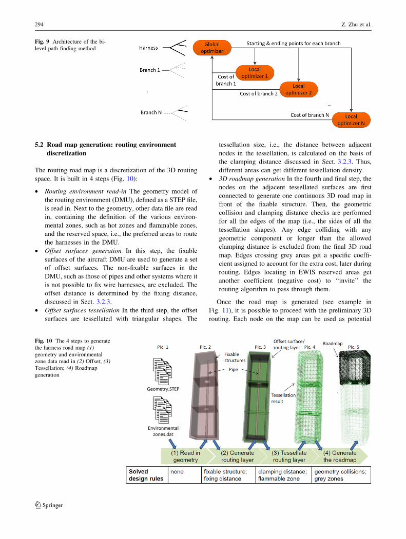
5.2 Road map generation: routing environment
discretization
The routing road map is a discretization of the 3D routing
space. It is built in 4 steps (Fig. 10):
• Routing environment read-in The geometry model of
the routing environment (DMU), defined as a STEP file,
is read in. Next to the geometry, other data file are read
in, containing the definition of the various environ-
mental zones, such as hot zones and flammable zones,
and the reserved space, i.e., the preferred areas to route
the harnesses in the DMU.
• Offset surfaces generation In this step, the fixable
surfaces of the aircraft DMU are used to generate a set
of offset surfaces. The non-fixable surfaces in the
DMU, such as those of pipes and other systems where it
is not possible to fix wire harnesses, are excluded. The
offset distance is determined by the fixing distance,
discussed in Sect. 3.2.3.
• Offset surfaces tessellation In the third step, the offset
surfaces are tessellated with triangular shapes. The
tessellation size, i.e., the distance between adjacent
nodes in the tessellation, is calculated on the basis of
the clamping distance discussed in Sect. 3.2.3. Thus,
different areas can get different tessellation density.
• 3D roadmap generation In the fourth and final step, the
nodes on the adjacent tessellated surfaces are first
connected to generate one continuous 3D road map in
front of the fixable structure. Then, the geometric
collision and clamping distance checks are performed
for all the edges of the map (i.e., the sides of all the
tessellation shapes). Any edge colliding with any
geometric component or longer than the allowed
clamping distance is excluded from the final 3D road
map. Edges crossing grey areas get a specific coeffi-
cient assigned to account for the extra cost, later during
routing. Edges locating in EWIS reserved areas get
another coefficient (negative cost) to ‘‘invite’’ the
routing algorithm to pass through them.
Once the road map is generated (see example in
Fig. 11), it is possible to proceed with the preliminary 3D
routing. Each node on the map can be used as potential
Fig. 9 Architecture of the bi-
level path finding method
Fig. 10 The 4 steps to generate
the harness road map (1)
geometry and environmental
zone data read in (2) Offset; (3)
Tessellation; (4) Roadmap
generation
294 Z. Zhu et al.
123
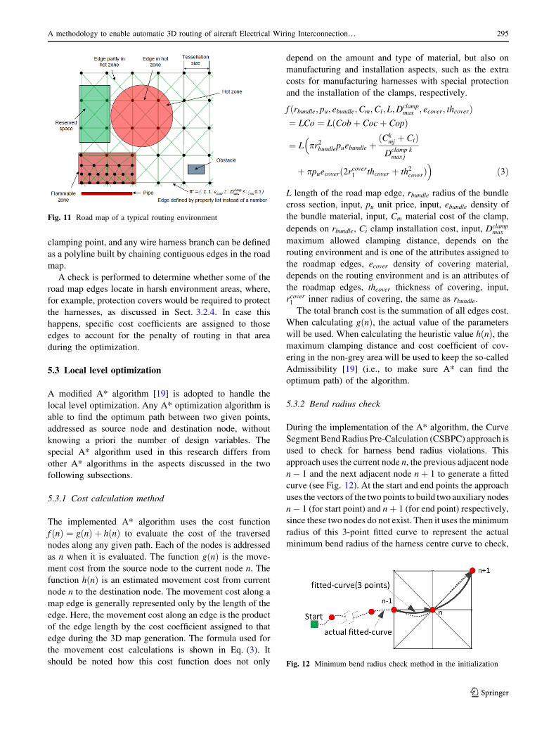
clamping point, and any wire harness branch can be defined
as a polyline built by chaining contiguous edges in the road
map.
A check is performed to determine whether some of the
road map edges locate in harsh environment areas, where,
for example, protection covers would be required to protect
the harnesses, as discussed in Sect. 3.2.4. In case this
happens, specific cost coefficients are assigned to those
edges to account for the penalty of routing in that area
during the optimization.
5.3 Local level optimization
A modified A* algorithm [19] is adopted to handle the
local level optimization. Any A* optimization algorithm is
able to find the optimum path between two given points,
addressed as source node and destination node, without
knowing a priori the number of design variables. The
special A* algorithm used in this research differs from
other A* algorithms in the aspects discussed in the two
following subsections.
5.3.1 Cost calculation method
The implemented A* algorithm uses the cost function
f nð Þ ¼ g nð Þ þ hðnÞ to evaluate the cost of the traversed
nodes along any given path. Each of the nodes is addressed
as n when it is evaluated. The function gðnÞ is the move-
ment cost from the source node to the current node n. The
function hðnÞ is an estimated movement cost from current
node n to the destination node. The movement cost along a
map edge is generally represented only by the length of the
edge. Here, the movement cost along an edge is the product
of the edge length by the cost coefficient assigned to that
edge during the 3D map generation. The formula used for
the movement cost calculations is shown in Eq. (3). It
should be noted how this cost function does not only
depend on the amount and type of material, but also on
manufacturing and installation aspects, such as the extra
costs for manufacturing harnesses with special protection
and the installation of the clamps, respectively.
f ðrbundle; pu; ebundle;Cm;Ci; L;Dclampmax ; ecover; thcoverÞ
¼ LCo ¼ LðCobþ Cocþ CopÞ
¼ L�pr2bundlepuebundle þ
ðCkmj þ CiÞD
clamp kmax j
þ ppuecoverð2rcover1 thcover þ th2coverÞ�
ð3Þ
L length of the road map edge, rbundle radius of the bundle
cross section, input, pu unit price, input, ebundle density of
the bundle material, input, Cm material cost of the clamp,
depends on rbundle, Ci clamp installation cost, input, Dclampmax
maximum allowed clamping distance, depends on the
routing environment and is one of the attributes assigned to
the roadmap edges, ecover density of covering material,
depends on the routing environment and is an attributes of
the roadmap edges, thcover thickness of covering, input,
rcover1 inner radius of covering, the same as rbundle.
The total branch cost is the summation of all edges cost.
When calculating gðnÞ, the actual value of the parameters
will be used. When calculating the heuristic value hðnÞ, themaximum clamping distance and cost coefficient of cov-
ering in the non-grey area will be used to keep the so-called
Admissibility [19] (i.e., to make sure A* can find the
optimum path) of the algorithm.
5.3.2 Bend radius check
During the implementation of the A* algorithm, the Curve
Segment BendRadius Pre-Calculation (CSBPC) approach is
used to check for harness bend radius violations. This
approach uses the current node n, the previous adjacent node
n� 1 and the next adjacent node nþ 1 to generate a fitted
curve (see Fig. 12). At the start and end points the approach
uses the vectors of the two points to build two auxiliary nodes
n� 1 (for start point) and nþ 1 (for end point) respectively,
since these two nodes do not exist. Then it uses the minimum
radius of this 3-point fitted curve to represent the actual
minimum bend radius of the harness centre curve to check,
Fig. 11 Road map of a typical routing environment
Fig. 12 Minimum bend radius check method in the initialization
A methodology to enable automatic 3D routing of aircraft Electrical Wiring Interconnection… 295
123
by means of a bend radius violation check function, whether
the next node nþ 1 is suitable for the harness. The check
starts from the start point and continues until the target point
is found that has minimum cost on f ðnÞ and does not violatethe minimum bend radius condition.
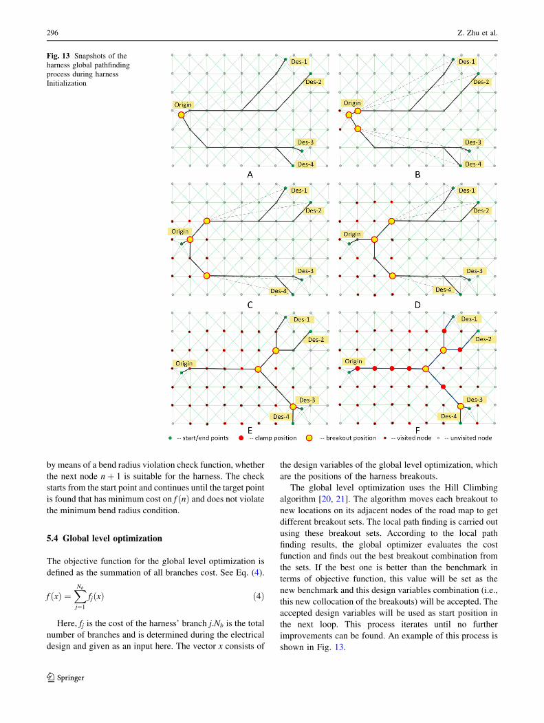
5.4 Global level optimization
The objective function for the global level optimization is
defined as the summation of all branches cost. See Eq. (4).
f ðxÞ ¼XNb
j¼1
fjðxÞ ð4Þ
Here, fj is the cost of the harness’ branch j.Nb is the total
number of branches and is determined during the electrical
design and given as an input here. The vector x consists of
the design variables of the global level optimization, which
are the positions of the harness breakouts.
The global level optimization uses the Hill Climbing
algorithm [20, 21]. The algorithm moves each breakout to
new locations on its adjacent nodes of the road map to get
different breakout sets. The local path finding is carried out
using these breakout sets. According to the local path
finding results, the global optimizer evaluates the cost
function and finds out the best breakout combination from
the sets. If the best one is better than the benchmark in
terms of objective function, this value will be set as the
new benchmark and this design variables combination (i.e.,
this new collocation of the breakouts) will be accepted. The
accepted design variables will be used as start position in
the next loop. This process iterates until no further
improvements can be found. An example of this process is
shown in Fig. 13.
Fig. 13 Snapshots of the
harness global pathfinding
process during harness
Initialization
296 Z. Zhu et al.
123
6 Harness 3D routing Refinement
After the generation of the preliminary harness definition,
the Refinement step starts with the coordinates of clamping
points and breakout positions as design variables. The
Refinement is in charge of refining the position of clamps
and breakouts (but not their number!) to solve the limita-
tions of the Initialization, namely, to eliminate the viola-
tions of some design rules and to optimize the preliminary
harness routing even further.
6.1 Limitations of the Initialization step
The preliminary harness routing performed in the Initial-
ization step by means of the road map has a number of
limitations, which generally prevents achieving not only an
optimal wire harness routing, but even a feasible solution.
6.1.1 Inter-harness and inner-harness geometric collision
A wiring zone may contain more harnesses. The path finding
in the Initialization is implemented on each harness individ-
ually, without considering the presence of other harnesses.
Hence, in some cases, different harnesses may share the same
edge and/or vertex of the road map, which means geometric
collision between different harnesses. Different branches of
the same harness may also have a similar problem.
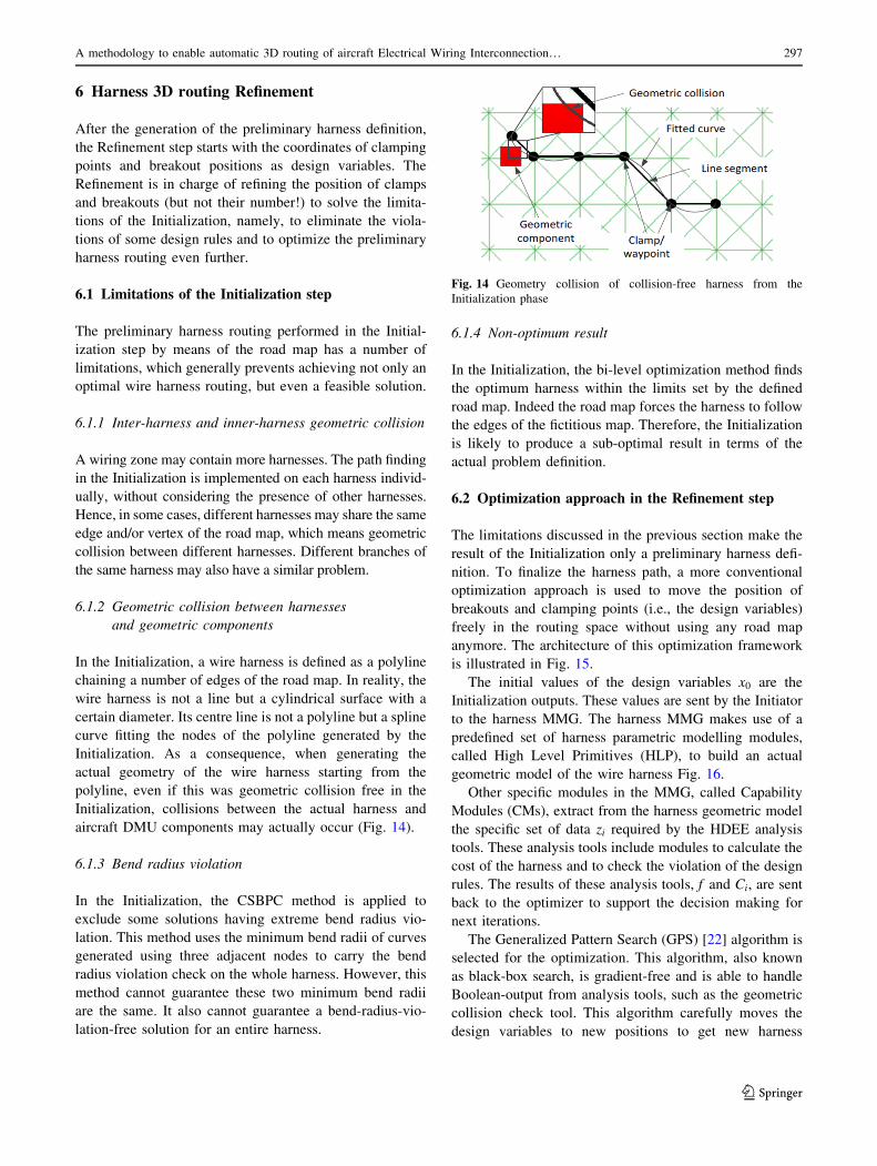
6.1.2 Geometric collision between harnesses
and geometric components
In the Initialization, a wire harness is defined as a polyline
chaining a number of edges of the road map. In reality, the
wire harness is not a line but a cylindrical surface with a
certain diameter. Its centre line is not a polyline but a spline
curve fitting the nodes of the polyline generated by the
Initialization. As a consequence, when generating the
actual geometry of the wire harness starting from the
polyline, even if this was geometric collision free in the
Initialization, collisions between the actual harness and
aircraft DMU components may actually occur (Fig. 14).
6.1.3 Bend radius violation
In the Initialization, the CSBPC method is applied to
exclude some solutions having extreme bend radius vio-
lation. This method uses the minimum bend radii of curves
generated using three adjacent nodes to carry the bend
radius violation check on the whole harness. However, this
method cannot guarantee these two minimum bend radii
are the same. It also cannot guarantee a bend-radius-vio-
lation-free solution for an entire harness.
6.1.4 Non-optimum result
In the Initialization, the bi-level optimization method finds
the optimum harness within the limits set by the defined
road map. Indeed the road map forces the harness to follow
the edges of the fictitious map. Therefore, the Initialization
is likely to produce a sub-optimal result in terms of the
actual problem definition.
6.2 Optimization approach in the Refinement step
The limitations discussed in the previous section make the
result of the Initialization only a preliminary harness defi-
nition. To finalize the harness path, a more conventional
optimization approach is used to move the position of
breakouts and clamping points (i.e., the design variables)
freely in the routing space without using any road map
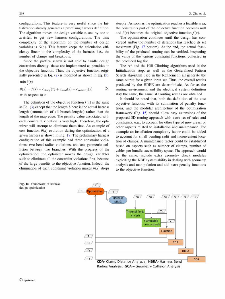
anymore. The architecture of this optimization framework
is illustrated in Fig. 15.
The initial values of the design variables x0 are the
Initialization outputs. These values are sent by the Initiator
to the harness MMG. The harness MMG makes use of a
predefined set of harness parametric modelling modules,
called High Level Primitives (HLP), to build an actual
geometric model of the wire harness Fig. 16.
Other specific modules in the MMG, called Capability
Modules (CMs), extract from the harness geometric model
the specific set of data zi required by the HDEE analysis
tools. These analysis tools include modules to calculate the
cost of the harness and to check the violation of the design
rules. The results of these analysis tools, f and Ci, are sent
back to the optimizer to support the decision making for
next iterations.
The Generalized Pattern Search (GPS) [22] algorithm is
selected for the optimization. This algorithm, also known
as black-box search, is gradient-free and is able to handle
Boolean-output from analysis tools, such as the geometric
collision check tool. This algorithm carefully moves the
design variables to new positions to get new harness
Fig. 14 Geometry collision of collision-free harness from the
Initialization phase
A methodology to enable automatic 3D routing of aircraft Electrical Wiring Interconnection… 297
123
configurations. This feature is very useful since the Ini-
tialization already generates a promising harness definition.
The algorithm moves the design variable xi one by one to
xi � Dx, to get new harness configurations. The time
complexity of the algorithm on the number of design
variables is OðnÞ. This feature keeps the calculation effi-
ciency linear to the complexity of the harness, i.e., the
number of clamps and breakouts.
Since the pattern search is not able to handle design
constraints directly, these are implemented as penalties in
the objective function. Thus, the objective function origi-
nally presented in Eq. (2) is modified as shown in Eq. (5).
min hxðxÞ
h xð Þ ¼ f ðxÞ þ cclampðxÞ þ cbendðxÞ þ cgeometryðxÞwith respect to x
ð5Þ
The definition of the objective function f ðxÞ is the same
as Eq. (3) except that the length L here is the actual harness
length (summation of all branch lengths) rather than the
length of the map edge. The penalty value associated with
each constraint violation is very high. Therefore, the opti-
mizer will attempt to eliminate them first. An example of
cost function hðxÞ evolution during the optimization of a
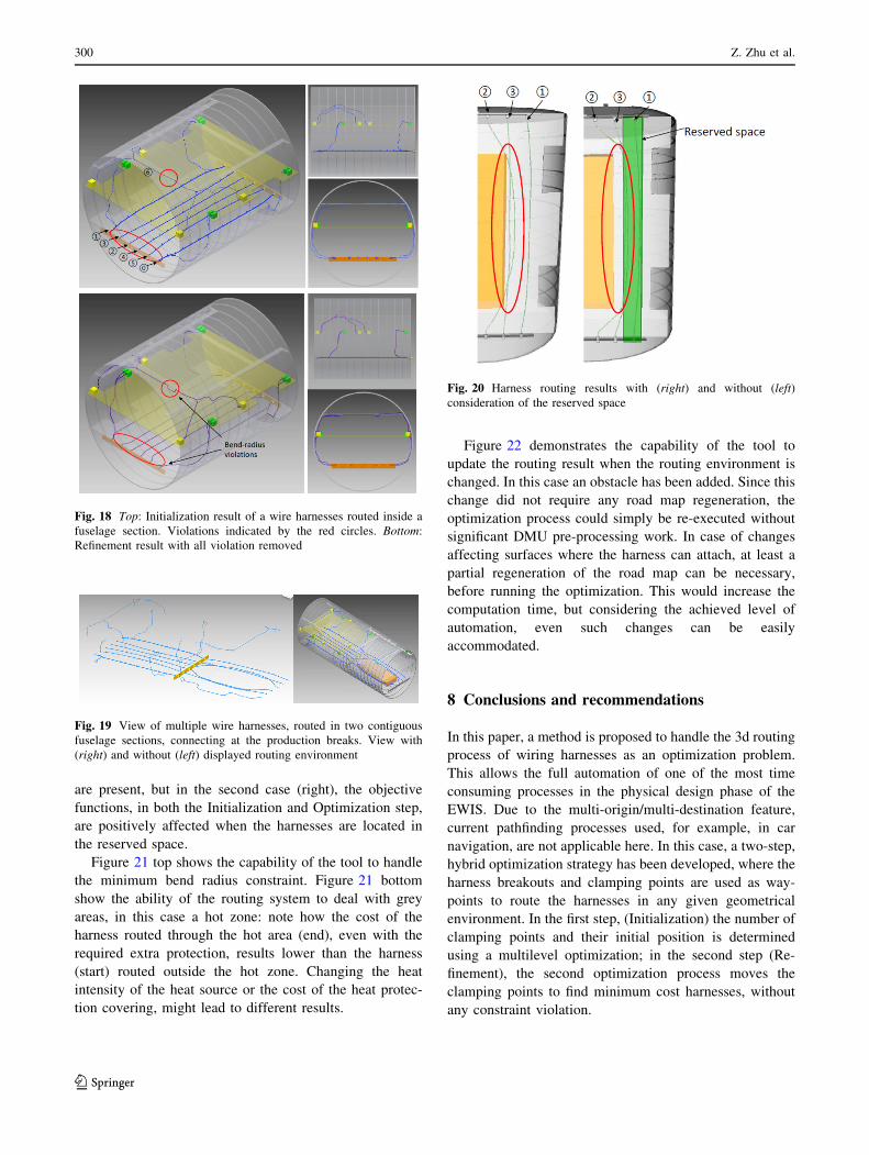
given harness is shown in Fig. 17. The preliminary harness
configuration of this example had three constraint viola-
tions: two bend radius violations, and one geometric col-
lision between two branches. With the progress of the
optimization, the optimizer moves the design variables
such to eliminate all the constraint violations first, because
of the large benefits to the objective function. Indeed, the
elimination of each constraint violation makes hðxÞ drops
steeply. As soon as the optimization reaches a feasible area,
the constraints part of the objective function becomes null
and hðxÞ becomes the original objective function f ðxÞ.The optimization continues until the design has con-
verged and/or the number of iterations has reached its set
maximum (Fig. 17 bottom). At the end, the actual feasi-
bility of the produced routing can be verified, inspecting
the value of the various constraint functions, collected in
the produced log file.
The A* and the Hill Climbing algorithms used in the
Initialization step, as well as the Generalized Pattern
Search algorithm used in the Refinement, all generate the
same output for a given input set. Thus, the overall results
produced by the HDEE are deterministic. As far as the
routing environment and the electrical system definition
stay the same, the same 3D routing results are obtained.
It should be noted that, both the definition of the cost
objective function, with its summation of penalty func-
tions, and the modular architecture of the optimization
framework (Fig. 15) should allow easy extensions of the
proposed 3D routing approach with extra set of rules and
constraints, e.g., to account for other type of grey areas, or
other aspects related to installation and maintenance. For
example an installation complexity factor could be added
to account for small bending radii and inconvenient loca-
tion of clamps. A maintenance factor could be established
based on aspects such as number of clamps, number of
cables per bundle, accessibility space. The approach would
be the same: include extra geometry check modules
exploiting the KBE system ability in dealing with geometry
analysis and manipulation and add extra penalty functions
to the objective function.
Fig. 15 Framework of harness
design optimization
298 Z. Zhu et al.
123
7 Results
The proposed two-steps hybrid optimization approach has
been implemented into the HDEE framework introduced in
Sect. 4.2. Several test cases have been performed to vali-
date the functionality of the application. The actual results
of the routing process, i.e., the 3D models of the produced
harnesses can be visualized immediately within the HDEE,
and/or exported in the form of STEP files, and/or plain
ASCII files (detailing the location and orientation of all the
clamps and breakout points, as well as the diameters of all
the branches). Using STEP files, the geometry model of the
routed harness can be immediately transferred into the
CAD system that was used to generate/deliver the DMU in
the first place. Otherwise, some macros could be developed
in the destination CAD system to automatically re-generate
the geometry of the routed harness, based on ASCII files
mentioned before. The export options provided by the
HDEE are of paramount importance, because these options
remove the need of a direct integration of the HDEE, or
any of its capabilities, with the CAD system used by the
EWIS manufacturer. As a consequence the HDEE capa-
bilities remain intact when the version or even the type of
CAD system changes per programs or manufacturer.
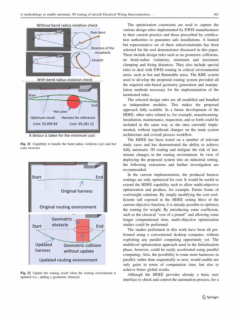
A few results produced by the HDEE are showed below
here. Figure 18 shows routing results inside a fuselage
barrel at the end of the Initialization and Refinement phase,
respectively.
Figure 19 show the results of the routing process inde-
pendently applied to two contiguous fuselage barrels, one
including a geometrical obstacle in the cargo bay. The
harness of the front and rear barrel connect at the pro-
duction breaks. If the routing environment in one of the
two barrel changes, the routing process can be re-executed
only in that one, as far as the production breaks remain at
the same location.
It should be noted that in case multiple harnesses need to
be routed in the same environment, as in the previous
example, the optimization process is performed one har-
ness at time. Geometric collision between different har-
nesses is prevented by adding the previously routed harness
to the list of the geometric components included in the
routing environment. Since the order in which the har-
nesses are routed influences the final result, a sequencing
rule has been implemented, based on EWIS manufacturers’
best practice, that is, the thickest harness is always routed
first. In real practice this is generally done because the
thickest is also the most rigid and difficult to rework, but
this approach does not guarantee to lead to a global opti-
mum design. An interesting extension to the proposed
approach would be that of routing all the harness belonging
to a given area simultaneously. This would be possible at
the expense of a much large computational cost.
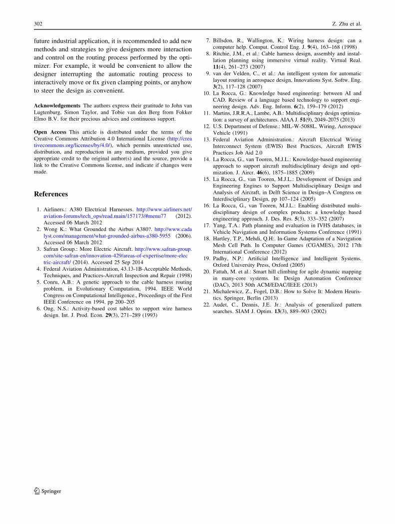
Figure 20 shows the effect of a reserved space definition
on the routing results. In both cases no constraint violations
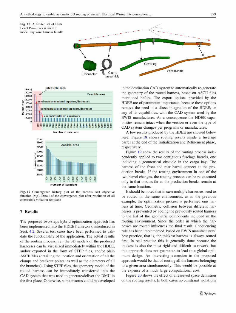
Fig. 16 A limited set of High
Level Primitives is used to
model any wire harness bundle
Fig. 17 Convergence history plot of the harness cost objective
function (top). Detail of the convergence plot after resolution of all
constraints violation (bottom)
A methodology to enable automatic 3D routing of aircraft Electrical Wiring Interconnection… 299
123
are present, but in the second case (right), the objective
functions, in both the Initialization and Optimization step,
are positively affected when the harnesses are located in
the reserved space.
Figure 21 top shows the capability of the tool to handle
the minimum bend radius constraint. Figure 21 bottom
show the ability of the routing system to deal with grey
areas, in this case a hot zone: note how the cost of the
harness routed through the hot area (end), even with the
required extra protection, results lower than the harness
(start) routed outside the hot zone. Changing the heat
intensity of the heat source or the cost of the heat protec-
tion covering, might lead to different results.
Figure 22 demonstrates the capability of the tool to
update the routing result when the routing environment is
changed. In this case an obstacle has been added. Since this
change did not require any road map regeneration, the
optimization process could simply be re-executed without
significant DMU pre-processing work. In case of changes
affecting surfaces where the harness can attach, at least a
partial regeneration of the road map can be necessary,
before running the optimization. This would increase the
computation time, but considering the achieved level of
automation, even such changes can be easily
accommodated.
8 Conclusions and recommendations
In this paper, a method is proposed to handle the 3d routing
process of wiring harnesses as an optimization problem.
This allows the full automation of one of the most time
consuming processes in the physical design phase of the
EWIS. Due to the multi-origin/multi-destination feature,
current pathfinding processes used, for example, in car
navigation, are not applicable here. In this case, a two-step,
hybrid optimization strategy has been developed, where the
harness breakouts and clamping points are used as way-
points to route the harnesses in any given geometrical
environment. In the first step, (Initialization) the number of
clamping points and their initial position is determined
using a multilevel optimization; in the second step (Re-
finement), the second optimization process moves the
clamping points to find minimum cost harnesses, without
any constraint violation.
Fig. 18 Top: Initialization result of a wire harnesses routed inside a
fuselage section. Violations indicated by the red circles. Bottom:
Refinement result with all violation removed
Fig. 19 View of multiple wire harnesses, routed in two contiguous
fuselage sections, connecting at the production breaks. View with
(right) and without (left) displayed routing environment
Fig. 20 Harness routing results with (right) and without (left)
consideration of the reserved space
300 Z. Zhu et al.
123
The optimization constraints are used to capture the
various design rules implemented by EWIS manufacturers
in their current practice and those prescribed by certifica-
tion authorities to guarantee safe installations. A limited
but representative set of these rules/constraints has been
selected for the tool demonstrator discussed in this paper.
These include design rules such as no geometric collisions,
no bend-radius violations, minimum and maximum
clamping and fixing distances. They also include special
rules to deal with EWIS routing in critical environmental
areas, such as hot and flammable areas. The KBE system
used to develop the proposed routing system provided all
the required rule-based geometry generation and manipu-
lation methods necessary for the implementation of the
mentioned rules.
The selected design rules are all modelled and handled
as independent modules. This makes the proposed
approach fully scalable. In a future development of the
HDEE, other rules related to, for example, manufacturing,
installation, maintenance, inspection, and so forth could be
included in the same way as the ones currently imple-
mented, without significant changes on the main system
architecture and overall process workflow.
The HDEE has been tested on a number of relevant
study cases and has demonstrated the ability to achieve
fully automatic 3D routing and mitigate the risk of last-
minute changes in the routing environment. In view of
deploying the proposed system into an industrial setting,
the following extensions and further investigation are
recommended.
In the current implementation, the produced harness
routings are only optimized for cost. It would be useful to
extend the HDEE capability such to allow multi-objective
optimization and produce, for example, Pareto fronts of
cost/weight solutions. By simply modifying the cost coef-
ficients (all exposed in the HDEE setting files) of the
current objective function, it is already possible to optimize
the routing for weight. By introducing some coefficient,
such as the classical ‘‘cost of a pound’’ and allowing some
longer computational time, multi-objective optimization
studies could be performed.
The studies performed in this work have been all per-
formed using a conventional desktop computer, without
exploiting any parallel computing opportunity yet. The
multilevel optimization approach used in the Initialization
phase, however, could be easily accelerated using parallel
computing. Also, the possibility to route more harnesses in
parallel, rather than sequentially as now, would enable not
only gains in terms of computation time, but also to
achieve better global results.
Although the HDEE provides already a basic user
interface to check and control the automation process, for a
Direction of the receptacle
Over-bent
Smooth
A detour is taken for the minimum cost
Hot zone
Without bend radius violation check
With bend radius violation check
Optimum result Harness for reference
Cost: 49,181.12Cost: 33,499.84
Start
End
Fig. 21 Capability to handle the bend radius violation (top) and hot
zone (bottom)
Original routing environment
Original harness
Start End
Updated routing environment
Geometric obstacle
Updated harness
Start End
Geometric collision without update
Fig. 22 Update the routing result when the routing environment is
updated (i.e., adding a geometric obstacle)
A methodology to enable automatic 3D routing of aircraft Electrical Wiring Interconnection… 301
123
future industrial application, it is recommended to add new
methods and strategies to give designers more interaction
and control on the routing process performed by the opti-
mizer. For example, it would be convenient to allow the
designer interrupting the automatic routing process to
interactively move or fix given clamping points, or anyhow
to steer the design as convenient.
Acknowledgements The authors express their gratitude to John van
Lugtenburg, Simon Taylor, and Tobie van den Berg from Fokker
Elmo B.V. for their precious advices and continuous support.
Open Access This article is distributed under the terms of the
Creative Commons Attribution 4.0 International License (http://crea
tivecommons.org/licenses/by/4.0/), which permits unrestricted use,
distribution, and reproduction in any medium, provided you give
appropriate credit to the original author(s) and the source, provide a
link to the Creative Commons license, and indicate if changes were
made.
References
1. Airliners.: A380 Electrical Harnesses. http://www.airliners.net/
aviation-forums/tech_ops/read.main/157173/#menu77 (2012).
Accessed 06 March 2012
2. Wong K.: What Grounded the Airbus A380?. http://www.cada
lyst.com/management/what-grounded-airbus-a380-5955 (2006).
Accessed 06 March 2012
3. Safran Group.: More Electric Aircraft. http://www.safran-group.
com/site-safran-en/innovation-429/areas-of-expertise/more-elec
tric-aircraft/ (2014). Accessed 25 Sep 2014
4. Federal Aviation Administration, 43.13-1B-Acceptable Methods,
Techniques, and Practices-Aircraft Inspection and Repair (1998)
5. Conru, A.B.: A genetic approach to the cable harness routing
problem, in Evolutionary Computation, 1994. IEEE World
Congress on Computational Intelligence., Proceedings of the First
IEEE Conference on 1994. pp 200–205
6. Ong, N.S.: Activity-based cost tables to support wire harness
design. Int. J. Prod. Econ. 29(3), 271–289 (1993)
7. Billsdon, R., Wallington, K.: Wiring harness design: can a
computer help. Comput. Control Eng. J. 9(4), 163–168 (1998)
8. Ritchie, J.M., et al.: Cable harness design, assembly and instal-
lation planning using immersive virtual reality. Virtual Real.
11(4), 261–273 (2007)
9. van der Velden, C., et al.: An intelligent system for automatic
layout routing in aerospace design. Innovations Syst. Softw. Eng.
3(2), 117–128 (2007)
10. La Rocca, G.: Knowledge based engineering: between AI and
CAD. Review of a language based technology to support engi-
neering design. Adv. Eng. Inform. 6(2), 159–179 (2012)
11. Martins, J.R.R.A., Lambe, A.B.: Multidisciplinary design optimiza-
tion: a survey of architectures. AIAA J. 51(9), 2049–2075 (2013)12. U.S. Department of Defense.: MIL-W-5088L. Wiring, Aerospace
Vehicle (1991)
13. Federal Aviation Administration.: Aircraft Electrical Wiring
Interconnect System (EWIS) Best Practices, Aircraft EWIS
Practices Job Aid 2.0
14. La Rocca, G., van Tooren, M.J.L.: Knowledge-based engineering
approach to support aircraft multidisciplinary design and opti-
mization. J. Aircr. 46(6), 1875–1885 (2009)
15. La Rocca, G., van Tooren, M.J.L.: Development of Design and
Engineering Engines to Support Multidisciplinary Design and
Analysis of Aircraft, in Delft Science in Design–A Congress on
Interdisciplinary Design, pp 107–124 (2005)
16. La Rocca, G., van Tooren, M.J.L.: Enabling distributed multi-
disciplinary design of complex products: a knowledge based
engineering approach. J. Des. Res. 5(3), 333–352 (2007)
17. Yang, T.A.: Path planning and evaluation in IVHS databases, in
Vehicle Navigation and Information Systems Conference (1991)
18. Hartley, T.P., Mehdi, Q.H:. In-Game Adaptation of a Navigation
Mesh Cell Path. In Computer Games (CGAMES), 2012 17th
International Conference (2012)
19. Padhy, N.P.: Artificial Intelligence and Intelligent Systems.
Oxford University Press, Oxford (2005)
20. Fattah, M. et al.: Smart hill climbing for agile dynamic mapping
in many-core systems. In: Design Automation Conference
(DAC), 2013 50th ACM/EDAC/IEEE (2013)
21. Michalewicz, Z., Fogel, D.B.: How to Solve It: Modern Heuris-
tics. Springer, Berlin (2013)
22. Audet, C., Dennis, J.E. Jr.: Analysis of generalized pattern
searches. SIAM J. Optim. 13(3), 889–903 (2002)
302 Z. Zhu et al.
123