a methodology of signal coordination at network level · a methodology of signal coordination at...
TRANSCRIPT

1
A Methodology of Signal Coordination atNetwork Level
Abstract-Goal of coordination is to get the greatest number of vehicles through the system with the fewest stops in a comfortable manner But the problems like congestion, delay, energy consumption, environmental pollution, etc still remain in question if the traffic signals are not coordinated. Coordination of signals is achieved when the flow of traffic on a given phase of movement at one intersection is accommodated by a “go’’ phase on its arrival at the next signalized intersection. It enhances progressive movement of traffic streams at some specific speed without enforced halts and reduced overall delay. It reduces the speed variations and provides smooth traffic operation, which increases capacity, decreases energy consumption and reduces air and noise pollution. In this paper, a methodology has been suggested for the pre-timed signal coordination at network level by adopting different phase plans to reduce the vehicular delay.
I. INTRODUCTION
Traffic signal coordination is normally implemented to improve the level of service of a road or a network of roads, where the spacing of signals is such that isolated signal operation would cause excessive delays, stops and loss of capacity. The popular concept is that coordinating traffic signals is simply to provide green-wave progression whereby a motorist travelling along a road receives successive green signals. While this is one of the aims, the principal purpose of coordination is to minimize overall delay and/or number of stops. The benefit of traffic signal coordination is based on the relationship .Travel speed along a roadway system is dependent on the signal spacing and the cycle length at traffic signals Travel speeds are lower when traffic signals are closely spaced and operate under a short cycle length. Conversely, higher travel speeds are a result of long cycle lengths and large spacing between intersections. When traffic signals are located in close proximity, the presence of the upstream traffic signals alters the arrival pattern of traffic at the downstream traffic signals from random arrivals to arrivals in platoons.
1
M.E student in Civil Transportation at LDCE.email: [email protected] Assistant Professor in civil engineering, Govt. engineering Bhuj ,Gujarat, India. Email: [email protected] Assistant Professor in civil engineering, L.E. college of engineering Morbi ,Gujarat, India.email: [email protected]
This means that improved traffic flow can be achieved if the green signal at the downstream traffic signal is arranged to coincide with the arrival of the platoon. To achieve this, traffic signals are coordinated, sometimes called “linked”. This improves the level of service on a road network where the spacing of traffic signals is such that isolated operation causes excessive delays.
II. GLOSSARY OF COMMONLY USED TERMS
Phase – a predetermined set of traffic signal movements that operate concurrently.
Signal phase – The portion of signal cycle that serves a combination of traffic movements.
Phase sequence – The order of appearance of signal phases during a signal cycle.
Cycle time – the total time taken to run once through all phases for an intersection.
Offset – For coordinated traffic signals the beginning or end of the green period on the coordinated approach of each intersection is set to occur a given time relative to that at the reference intersection. This time is known as the offset.( Traffic Engineering handbook)
III. COORDINATION FEATURES
1. Traffic signals run on a common cycle time (or in special cases, one half of the cycle time).
2. The beginning or end of the green period on the coordinated approach of each intersection is set to occur at the offset time relative to that at the referenceintersection. This offset is determined by the distance between the signals, the progression speed along the road, and the queues of vehicles waiting at red signals.
3. The optimization of offsets and phaseSource: Coordination of traffic signal, information for the load impact committee, Australia 2009
IV. BENEFITS OF SIGNAL COORDINATION
Reduced delays and minimum stops. Improved mobility and access. Reduced vehicular accidents.
A. Khushboo M. Patel1, B. Dr. H.R. Varia2, and C. Dr. P.J. Gundaliya3
13-14 May 2011 B.V.M. Engineering College, V.V.Nagar,Gujarat,India
National Conference on Recent Trends in Engineering & Technology

2
Reduced energy and fuel consumption. Eliminated or delayed street widening needs. Improved emergency response. Reduced motorist frustration and road rage. Reduced vehicle wear. Increased control of travel speeds. Reduced diversionary flows in neighborhoods. Reduced vehicle emissions. Improved capacity of groups of closely spaced
traffic signals. Reduction in overall network travel time and
delay. Reduction in the overall network number of stops. Reduction in intersection crashes. Reduction in noise levels.
Source: Coordination of traffic signal, information for the load impact committee, Australia 2009
V. INHERENT LIMITATIONS TO COORDINATION
Coordination does not mean that there will be no delays for traffic, rather that the level of delay is minimized. This is because:
As all traffic signals have different traffic flows, and often have different phasing, so the amount of green time available to the coordinated approaches varies along a coordinated route. Therefore, it is often inevitable that some traffic in the platoon is stopped somewhere along the coordinated route.
It is necessary to start the green period on the coordinated route sufficiently in advance of the arrival of the platoon to allow any queues of traffic stopped at the downstream traffic signals to clear. These times accumulate for subsequent traffic signals along the route, progressively reducing the green-time available for the original platoon.
Coordination cannot improve the capacity of an intersection above that it would have under independent operation. However, it can improve the capacity of intersections that are closely spaced and therefore have strongly interacting traffic queues.
Outside periods of strong “tidal” traffic flow (i.e. outside peak hours) traffic along arterial roads is typically balanced, so two-directional coordination is required. It is extremely rare that intersection green times, spacing and travel time align to allow for complete two-way coordination. Normally a compromise coordination plan is required, which minimises (i.e. does not reduce to zero) stops and delays in both directions.
The mix of traffic is also an important consideration when determining offsets. Large trucks take longer to accelerate than passenger cars, so offsets that are ideal
for passenger cars may result in heavy trucks being stopped at the next set of traffic signals. Also, if the offsets were set for heavy traffic this would result in additional traffic congestion, thereby adding delay for all traffic (including heavy traffic). As a result, on major freight routes it is often necessary to have compromise offsets that are not ideal for either passenger cars or heavy trucks.
Better coordination along an arterial road most often results in increased delays to side-street traffic. During peak hours the overall delays to all traffic (i.e. including side-streets) are lower as a result of the coordination, so this can be justified. However, as traffic flow along the arterial road reduces (i.e. at night) the justification for imposing additional delays on traffic on the side streets reduces. So in a period of low flows coordination is not justified.
Source: Coordination of traffic signal, information for the load impact committee, Australia 2009
VI. AIM
To design signal for small network to minimize over all delay.
It can be selected congested area signalized intersection after collecting data of signal and measure of traffic management will be suggested to minimize the travel time delay.
VI. ADOPTED METHODOLOGY FOR SIGNAL COORDINATION
On the congested network when the traffic flow on four directions (forward and backward) is heavy, four-way coordination is desirable to provide minimum delay to the vehicles. If the intersections are close (less than 1000 m), it is advisable to adopt equal signal cycle time and equal phase time on each intersection to avoid unnecessary delay to the vehicles and also to provide smooth uninterrupted flow pattern in all directions. Proper phase plan and its sequence are also very important to avoid delay. In this study four arm junctions with four phases are considered, which are generally found in Indian cities. It is also considered that left turners have always green. Travel time in both directions is also assumed same. The phase sequence shall be adjusted such that right turners entering to main corridor and straight movers entering to main corridor on same direction should have minimum time difference to reach at the next intersection. If straight movers are more (i.e. through traffic flow is higher) than right turners, straight flow should be given second priority to get minimum delay on next intersection for clearance. Thus, through traffic and right turners should get quicker clearance on major corridor in all the directions. Unequal phase timing and improper phase
13-14 May 2011 B.V.M. Engineering College, V.V.Nagar,Gujarat,India
National Conference on Recent Trends in Engineering & Technology

3
sequence on two consecutive four arm junctions give larger delay to the vehicles, which is shown in Fig. 1. It can be seen that vehicles from the Intersection-I have to wait in queue for lager time interval on the Intersection-II in the forward direction. Similarly vehicles from Intersection-II have to wait for longer time interval on the Intersection-I in backward direction. If the equal phase timings and proper phase sequence are provided, then vehicles have to wait considerably lesser time interval in queue, which is shown in Fig. 2.
Fig. 1: Unequal phase timing, improper phase sequence
Fig. 2: Equal phase timing, proper phase sequence
In Figure no-1, Delay for the forward direction right movers is minimum three phase & straight movers is one phase. Reverse direction delay for straight & right movers is of one phase. In Figure no-2, Delay for the forward direction right movers is one phase & straight movers have no delay. Delay for the reverse direction right movers is one phase & straight movers have nodelay. So, the methodology discussed by Kadiya and Varia (2010) for the two way co-ordination of traffic signal on urban corridor is adopted in this paper. The authors have discussed that in two way signal coordination, average cycle time of the intersections of the corridor can be selected. For example, if cycle time on the intersections is varying between 100 sec to 140 sec, than an average cycle time of 120 Sec can be adopted on each intersection. For equal phase timings on four phase cycle of 120 sec, each phase of 30 sec (green + amber time) can be adopted. Phase difference between intersections depends on distance, average speed of traffic stream, geometrics of the link, vehicle composition and other reasons. According to phase difference, strategy of phase plan shall be adopted. For the simplicity of traffic flow operation, two types of phase plans, Phase plan-A and Phase plan-B are considered for the four arm junctions that are shown in Fig. 3.
13-14 May 2011 B.V.M. Engineering College, V.V.Nagar,Gujarat,India
National Conference on Recent Trends in Engineering & Technology
4
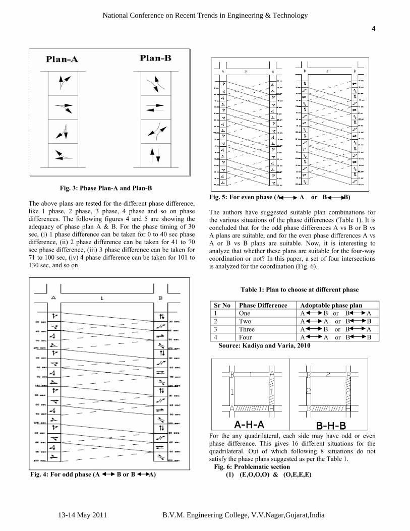
Fig. 3: Phase Plan-A and Plan-B
The above plans are tested for the different phase difference, like 1 phase, 2 phase, 3 phase, 4 phase and so on phase differences. The following figures 4 and 5 are showing the adequacy of phase plan A & B. For the phase timing of 30 sec, (i) 1 phase difference can be taken for 0 to 40 sec phase difference, (ii) 2 phase difference can be taken for 41 to 70 sec phase difference, (iii) 3 phase difference can be taken for 71 to 100 sec, (iv) 4 phase difference can be taken for 101 to 130 sec, and so on.
Fig. 4: For odd phase (A B or B A)
Fig. 5: For even phase (A A or B B)
The authors have suggested suitable plan combinations for the various situations of the phase differences (Table 1). It is concluded that for the odd phase differences A vs B or B vs A plans are suitable, and for the even phase differences A vs A or B vs B plans are suitable. Now, it is interesting to analyze that whether these plans are suitable for the four-way coordination or not? In this paper, a set of four intersections is analyzed for the coordination (Fig. 6).
Table 1: Plan to choose at different phase
Sr No Phase Difference Adoptable phase plan1 One A B or B A2 Two A A or B B3 Three A B or B A4 Four A A or B B
Source: Kadiya and Varia, 2010
For the any quadrilateral, each side may have odd or even phase difference. This gives 16 different situations for the quadrilateral. Out of which following 8 situations do not satisfy the phase plans suggested as per the Table 1.
Fig. 6: Problematic section(1) (E,O,O,O) & (O,E,E,E)
13-14 May 2011 B.V.M. Engineering College, V.V.Nagar,Gujarat,India
National Conference on Recent Trends in Engineering & Technology
5
(2) (E,E,E,O) & (O,O,O,E)(3) (E,O,E,E) & (O,E,O,O)(4) (E,E,O,E) & (O,O,E,O)
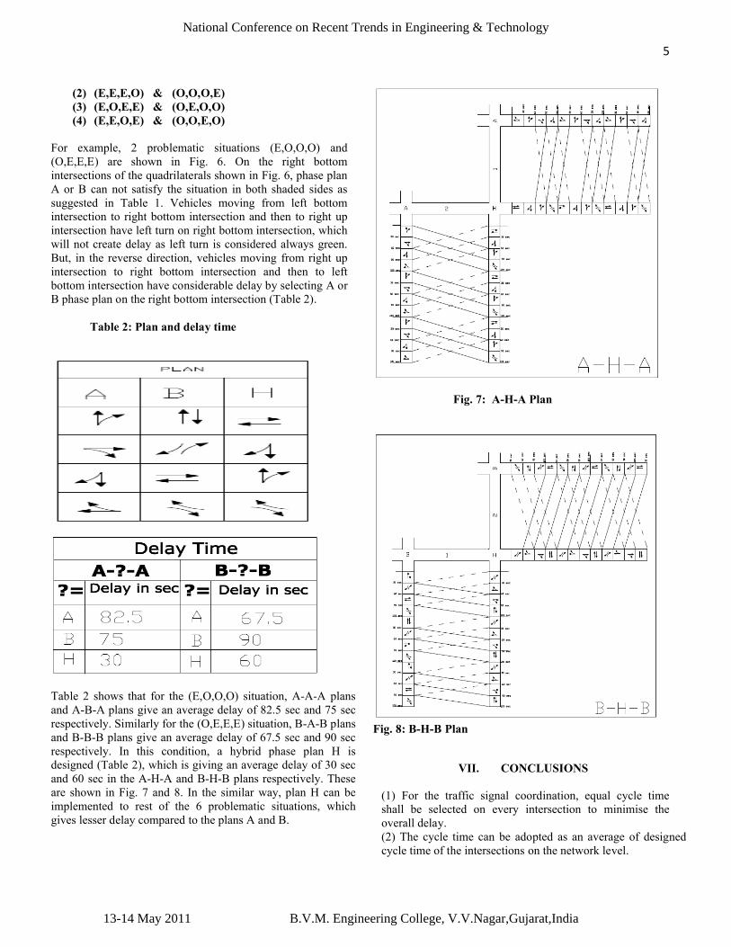
For example, 2 problematic situations (E,O,O,O) and (O,E,E,E) are shown in Fig. 6. On the right bottom intersections of the quadrilaterals shown in Fig. 6, phase plan A or B can not satisfy the situation in both shaded sides as suggested in Table 1. Vehicles moving from left bottom intersection to right bottom intersection and then to right up intersection have left turn on right bottom intersection, which will not create delay as left turn is considered always green. But, in the reverse direction, vehicles moving from right up intersection to right bottom intersection and then to left bottom intersection have considerable delay by selecting A or B phase plan on the right bottom intersection (Table 2).
Table 2: Plan and delay time
Table 2 shows that for the (E,O,O,O) situation, A-A-A plans and A-B-A plans give an average delay of 82.5 sec and 75 sec respectively. Similarly for the (O,E,E,E) situation, B-A-B plans and B-B-B plans give an average delay of 67.5 sec and 90 sec respectively. In this condition, a hybrid phase plan H is designed (Table 2), which is giving an average delay of 30 sec and 60 sec in the A-H-A and B-H-B plans respectively. These are shown in Fig. 7 and 8. In the similar way, plan H can be implemented to rest of the 6 problematic situations, which gives lesser delay compared to the plans A and B.
Fig. 7: A-H-A Plan
Fig. 8: B-H-B Plan
VII. CONCLUSIONS
(1) For the traffic signal coordination, equal cycle time shall be selected on every intersection to minimise the overall delay.(2) The cycle time can be adopted as an average of designed cycle time of the intersections on the network level.
13-14 May 2011 B.V.M. Engineering College, V.V.Nagar,Gujarat,India
National Conference on Recent Trends in Engineering & Technology

6
(3) Equal phase timings and proper selection of phase sequence can reduce delay considerably in signal coordination.(4) For the closer intersections, shorter cycle is more beneficial for quicker traffic movement and to eliminate the possible spillage of queues on up-stream intersections.(5) For the different phase offsets, different phase plan strategy can reduce delay considerably in signal coordination. In two way coordination, for the odd offset, A vs B or B vs A and for even offset, A vs A or B vs B plan can be adopted. (6) For the set of four intersections forming a quadrilateral, four-way coordination can be achieved by the above strategy mentioned in (5) except for the 8 problematic situations shown in section VII. For these situations hybrid plan H can be adopted to reduce the delay. Table 2 shows that plan A-H-A can reduce delay about 63% and plan B-H-B can reduce about 33% delay in the respective situations.(7) The above mentioned methodology is best suitable for the pre-timed signals on busy corridor for the signal coordination. For its implementation, there is no need of extra cost of soft-wares, sensors and other arrangements. This methodology can be easily adoptable to Indian traffic conditions and can be considered as an economic Traffic Management System.
References
1. Kadiya, D. K. and Varia, H. R. (2010) “Traffic signal coordination on urban corridor”, International conference CISTUP-2010, IISC Bangalore.
2. Kadiyali, L.R. (2000), “Traffic Engineering and Transport planning”, Khanna publishers, Nath market, Nai sarak, Delhi, India
3. Mcshane, W.R., Roess, R.P. and Prassas, E.S. (1998). “Traffic Engineering”, Prentice hall, New Jersey.
4. Oza, S. (2003), “Signal Coordination ’’ M.E.Dissertation, L.D.College of Engineering-Ahmedabad, India.
5. Traffic Engineeering handbook.(1999), “Institute of Transport Engineers”,5th edition.
13-14 May 2011 B.V.M. Engineering College, V.V.Nagar,Gujarat,India
National Conference on Recent Trends in Engineering & Technology