a low-cost soft modem using the freescale digital signal ... · pdf filea low-cost soft modem...
TRANSCRIPT

Freescale SemiconductorApplication Note
Document Number: AN3114Rev. 1, 03/2011
Contents
Introduction . . . . . . . . . . . . . . . . . . . . . . . . . . . . . . . . . . . 1System specification and design . . . . . . . . . . . . . . . . . . . 2
2.1 The soft modem system concept. . . . . . . . . . . . . . . 22.2 Soft modem specification and design . . . . . . . . . . . 52.3 Test harness specification and design . . . . . . . . . . 62.4 Hardware implementation, setup, and operation. . . 8Conclusion — system performance. . . . . . . . . . . . . . . . 11
3.1 Test setup . . . . . . . . . . . . . . . . . . . . . . . . . . . . . . . 113.2 Bit error rate test results . . . . . . . . . . . . . . . . . . . . 133.3 Dynamic range test results . . . . . . . . . . . . . . . . . . 243.4 Memory utilization on the 56F8357 . . . . . . . . . . . . 253.5 Core processor loading and RTOS . . . . . . . . . . . . 263.6 Peripheral footprint . . . . . . . . . . . . . . . . . . . . . . . . 263.7 Conclusions. . . . . . . . . . . . . . . . . . . . . . . . . . . . . . 28References . . . . . . . . . . . . . . . . . . . . . . . . . . . . . . . . . . 29
ppendix A Layout and government certifications. . . . . . . . . 30A.1 Design for performance. . . . . . . . . . . . . . . . . . . . . 30A.2 Design for agency approvals . . . . . . . . . . . . . . . . . 30
A Low-Cost Soft Modem Using the Freescale Digital Signal ControllerSupporting the low-cost soft modem reference design and customers incorporating a soft-modem into their products using the Freescale 56F8300 seriesby: John L. Winters
NOTE
The 56F8357EVM was used as the test vehicle, but is no longer available. The 56F8367EVM will yield similar results.
1 IntroductionThis note presents the hardware and software design of a low-cost V.21/V.22/V.22bis soft modem. The design does not include a traditional telecommunications Pulse Code Modulation Coder/Decoder (PCM codec), but instead uses the ADC and PWM of the Freescale 56F8300 series to implement a less complex solution. An optional serial port with AT command set is included as a test fixture. Modem performance figures measured on the implementation are included for reference.
12
3
4A
© Freescale Semiconductor, Inc., 2005, 2011. All rights reserved.

System specification and design
2 System specification and designThis section describes the system used to implement the soft modem, as well as the motivation for such a system. The system specification is followed by a block diagram and discussion of implementation.
2.1 The soft modem system conceptA soft modem is one that can be used to modulate/demodulate data to be sent serially over an analog channel directly, without the need for a serial data path to another entity to supply data or control signals. It includes a simple way to dial phone numbers, detect ringing signals, control the hook relay of the DAA, input and output analog data, connect with remote modems and communicate with them. Complete control of the modem is embedded within the same host computer performing other system functions, such as alarm monitoring or motion control. A soft modem is the enabling ingredient that allows combining the DTE/DCE into one entity.
This differs from traditional communication systems, which are broken into two parts: a DTE, or data terminal equipment, and a DCE, or data communication equipment. Traditionally, these equipments communicated via a 25-pin serial interface comprised of such signals as are described in the V.14, V.25 and V.22bis (and many other) specifications. These signals were used for flow control and complex signaling between the DTE and DCE as to what respective states they might have been in. With the advent of the AT command set in the 1980’s, many of these signals fell into disuse and the 25-pin DTE/DCE interface is now more typically found to be a nine-pin interface. The difference is made up in providing a complex set of commands and responses that attempt to keep the DTE and DCE in sync, depicted in Figure 1.
A Low-Cost Soft Modem Using the Freescale Digital Signal Controller, Rev. 1
Freescale Semiconductor2

System specification and design
Figure 1. Second millennium modem architecture
In the 1990’s, this interface all but disappeared when a modem designed only for Windows was developed. This spoofed the serial communications to the DCE, actually performing much of the modem function on the host processor. Only digital signal processing was done on another processor closely coupled to the PC on its bus. The DTE and DCE still were two intelligent processors, but the old serial interface was gone.
When the DTE and DCE were merged into one processor around the turn of the century, the need for such a cable or even bus, vanished, as did the need for a “serial port”. This is in fact how modems in PCs are implemented today. The host processor is powerful enough to implement the modem algorithms and does away with the DCE as a separate intelligent device. All that is needed is a way to send and receive analog signals over the phone line and to protect telephone equipment using the DAA. The “serial ports”, used only for PC communication software compatability, are complete spoofs.
This same elegant architecture, shown in Figure 2, can now exist in embedded systems.
The project described here shows the simplicity of such a design, how few resources of the processor it takes, and how well it performs on USA average lines. This design even omits the standard telecommunications codec, instead using a Pulse Width Modulation (PWM) for output and Analog-to-Digital Converter (ADC) for input. Since both of these peripherals are readily available from the many peripherals on one 56F8300 series device, along with more processing power than required from the single core, the design is a true one-chip, one-core system that includes telecommunications ability with room for even more system functionality.
Application with programthat talks to modem
ModemPhone line
A Low-Cost Soft Modem Using the Freescale Digital Signal Controller, Rev. 1
Freescale Semiconductor 3

System specification and design
Figure 2. Third millennium modem architecture
This approach has many applications in embedded systems. For example, a security system consisting of a single processor charged with monitoring local security sensors communicates directly over phone lines to a central reporting location. This reporting may be for the purpose of conveying the state of security.
Another application would be a portable medical device, such as a heart monitor, that could periodically interface directly to a phone line without the need for an external modem (or costly modem chip on board) of any kind. Without the DCE/DTE split, such a device would be more reliable and less expensive, while consuming less power.
While it would be possible to split the design into a DCE and a DTE, this would add cost, not just for the additional processor, but for the two serial ports required to connect them as well as for the software in both parts used for communication between the DTE and DCE, the interrupts and context saving and restoring that these engender. It would also add a potential failure scenario when the DCE and DTE do not observe each other’s states in a timely manner.
See the right side of Figure 3 for a block diagram illustrating a low-cost soft modem system utilizing Freescale’s 56F8357 controller. The left side of the same figure shows the test harness integrated with the system.
Application with soft modemPhone line
A Low-Cost Soft Modem Using the Freescale Digital Signal Controller, Rev. 1
Freescale Semiconductor4

System specification and design
Figure 3. Low-cost soft modem system
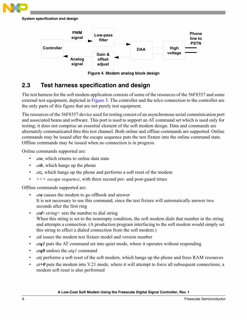
2.2 Soft modem specification and designFigure 4 shows how the basic modem, DTMF, and call progress detection are implemented. The DAA control signal, ring detect signal, flow control signal (for testing only) and the serial port (for testing only) are not shown.
The modem incorporates portions of the following standards as they apply to a soft modem: V.25, V.21, V.22, V.22bis, all implemented on the host controller. The portions of these standards related to the DTE/DCE interface are simply not required for a soft modem. PWM and ADC peripherals on the DSC pass digital samples at 7200 samples per second (SPS) for the modems and DTMF generation software. A sampling rate of 8000 SPS is used for the call progress software, used to detect dial tone. The smaller the sampling rate, the less work for the processor, and, subsequently, the less power used. The rate of 7200 SPS is ideal for these modems.
PC
Test fixture portion
Serial communication of test data is full duplex with flow control for data from PC in the test fixture
dataSCI
GPIOflow
control
GPIO
GPIO
ADC
PWM
Amplifier
Low-passfilter
Receive from phone line
DAA
Transmit to phone line
Off/on hook control
Phone line
Soft modem portion
56F8357
“Ring signal”—used for ring detect
A Low-Cost Soft Modem Using the Freescale Digital Signal Controller, Rev. 1
Freescale Semiconductor 5
System specification and design
Figure 4. Modem analog block design
2.3 Test harness specification and designThe test harness for the soft modem application consists of some of the resources of the 56F8357 and some external test equipment, depicted in Figure 5. The controller and the telco connection to the controller are the only parts of this figure that are not purely test equipment.
The resources of the 56F8357 device used for testing consist of an asynchronous serial comminication port and associated beans and software. This port is used to support an AT command set which is used only for testing; it does not comprise an essential element of the soft modem design. Data and commands are alternately communicated thru this test channel. Both online and offline commands are supported. Online commands may be issued after the escape sequence puts the test fixture into the online command state. Offline commands may be issued when no connection is in progress.
Online commands supported are:
• ato, which returns to online data state
• ath, which hangs up the phone
• atz, which hangs up the phone and performs a soft reset of the modem
• +++ escape sequence, with three second pre- and post-guard times
Offline commands supported are:
• ata causes the modem to go offhook and answerIt is not necessary to use this command, since the test fixture will automatically answer two seconds after the first ring
• atd<string> sets the number to dial stringWhen this string is set to the nonempty condition, the soft modem dials that number in the string and attempts a connection. (A production program interfacing to the soft modem would simply set this string to effect a dialed connection from the soft modem.)
• ati issues the modem test fixture model and version number
• atq1 puts the AT command set into quiet mode, where it operates without responding
• atq0 undoes the atq1 command
• atz performs a soft reset of the soft modem, which hangs up the phone and frees RAM resources
• at+0 puts the modem into V.21 mode, where it will attempt to force all subsequent connections; a modem soft reset is also performed
Controller
PWMsignal
Analogsignal
Low-pass filter
Gain & offset adjust
DAA High voltage
Phone line to PSTN
A Low-Cost Soft Modem Using the Freescale Digital Signal Controller, Rev. 1
Freescale Semiconductor6

System specification and design
at+2 puts the modem into V.22/V.22bis mode, where the modem will attempt to force all subsequent connections; a modem soft reset is also performed
The online data state of the test fixture is attained with the industry-standard escape sequence, consisting of a delay period of three seconds of no traffic on the serial test channel, three “plus” characters, and another three seconds of no activity on the serial test channel.
Connect messages are issued, indicating the line speed. The serial test channel operates at a fixed 2400 baud.
Characters are buffered into the test fixture for transmission and reception to and from the test fixture queues.
Figure 5. Modem test setup
The external test equipment consists of two types, that connected to the RJ11 telco jack of the soft modem, and that connected to a DB9 async serial port on the EVM. The telco jack is connected to equipment that simulates the USA average Public Switched Telephone Network (PSTN) connection to an off-the-shelf modem, a Hayes Accura V.92 modem. This PSTN simulation equipment consists of the TAS Series II Plus unit and the TAS Model 240 unit.
2.3.1 Terminal emulation one
Terminal Emulation One runs HyperTerminal on a PC at 2400 BPS, 8 bits data, no parity, 1 stop bit on a communication port. It runs a binary file transfer using one of the protocols included with HyperTerminal. It is connected to a Hayes Accura modem, where the AT command set is used to directly control the modem.
2.3.2 Terminal emulation two
Terminal Emulation Two is a HyperTerminal session at 9600 baud used to control the TAS Series II Plus unit. This unit is programmed to simulate USA average lines.
Terminal emulation
1
Terminal emulation
2
Terminal emulation
3
Terminal emulation
4
Hayes Accura
V.92
TAS Series II
Plus
TAS Model 240
Controller
Serial 2400
Serial 9600control
Serial 9600control
Serial 2400
TelcoSwitch to line
emulator connections
Telco
A Low-Cost Soft Modem Using the Freescale Digital Signal Controller, Rev. 1
Freescale Semiconductor 7
System specification and design
2.3.3 Terminal emulation three
Terminal Emulation Three controls the TAS Model 240, which for these tests supplies NULL line.
2.3.4 Terminal emulation four
Terminal Emulation Four is HyperTerminal on a PC at 2400 BPS 8 bits data, no parity, 1 stop bit, hardware flow control. It is the peer of Terminal Emulation One and runs the other end of the binary file transfer. The active signals in the DB9 include TX data, RX data, and one hardware flow control signal used to signal the PC when it may or may not send data. Flow control in the other direction was found to be unnecessary; due to the abundant resources of the PC, it never became flooded with data from the controller at 2400 BPS.
2.4 Hardware implementation, setup, and operationA standard off-the-shelf Freescale 56F8357EVM was used for this project. The Low-Cost Freescale Modem Demonstration Kit comes with a 56F8367EVM and a Low-Cost Modem Daughter Card (LCMDC) in one box. The EVM has a connector for this daughter card. The LCMDC was developed to house the Data Access Arrangement (DAA) as well as conditioning circuits for the single PWM signal from the EVM mother board.
To assemble the modem, snap the daughter card into the connector after making the following revisions to the EVM:
• To wire ring signal for detection by the controller, connect these two signals:
— PWMA 1 (Pin 2, J7) source is ring indicator from the daughter card
— Quadrature Decoder 0, PHASEA0 (Pin 1, J15) destination
• To wire flow control of data from serial test device to the controller, connect these two signals and a capacitor:
— SCI 1 TXD1 (Pin 1, J14) source
— RTS (Pin 1, J11) destination
— One end of a 39pF cap to RTS, the other end to ground
• Clip pins 3, 4, 5, 6 of J8 to provide clearance for the DAA high voltage section of the daughter card
The first connection connects the ring signal from the DAA to a counter, enabling ring detection functionality. The second connection connects a GPIO for flow control. To avoid noise-induced glitches on the flow control signal, a small capacitor (39pF) should connect the RTS signal to ground.
The Low-Cost Freescale Modem Demonstration Kit, available for evaluation upon reservation, contains an EVM factory modified as specified previously. The kit also includes documentation, as well as the LCMDC and required cables.
A Low-Cost Soft Modem Using the Freescale Digital Signal Controller, Rev. 1
Freescale Semiconductor8

System specification and design
2.4.1 Pulse-width modulation telephony base band transmission
The signal to be transmitted over the phone line is developed first as a PWM signal; its duty cycle is the analog of the signal value. This signal is then filtered to produce a real analog signal in the voice band. In the hardware it is done as described below.
One of the PWM channels of the 56F8367 outputs a PWM signal on pin 130, Timer D, Channel 1 (TD1). This signal is available on the daughter card via pin 70 of the connector to the EVM. This PWM is associated with the OutputTimer bean. This signal enters from the left of Figure 6, where it is limited to 4kHz by a 4th order active low-pass filter. The filtered signal is then passed on to the left of Figure 7 for level setting.
Figure 6. TD1 into active 4 kHz 4th order filter to TP7
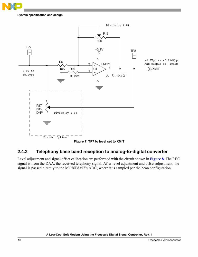
The ouput, XMIT, from Figure 6 is then passed to the XMIT input of a Cermetek CH 1837A DAA whose output level is set to -9dBm via adjustment of R18. R17 is not populated.
A Low-Cost Soft Modem Using the Freescale Digital Signal Controller, Rev. 1
Freescale Semiconductor 9
System specification and design
Figure 7. TP7 to level set to XMIT
2.4.2 Telephony base band reception to analog-to-digital converter
Level adjustment and signal offset calibration are performed with the circuit shown in Figure 8. The REC signal is from the DAA, the received telephony signal. After level adjustment and offset adjustment, the signal is passed directly to the MC56F8357’s ADC, where it is sampled per the bean configuration.
A Low-Cost Soft Modem Using the Freescale Digital Signal Controller, Rev. 1
Freescale Semiconductor10

Conclusion — system performance
Figure 8. REC to offset and gain to ANA6
3 Conclusion — system performanceThe modem is fully capable of error-free operation over average telephone lines in the USA. Limitations to performance are inherent in the limited dynamic range of the AGC. If desired, such limitation may be overcome by the addition of a hardware AGC circuit, since the amplitude variation of a land line telephone circuit over time is not dramatic.
Modem performance curves indicate that the modem meets the performance standards required for V.22bis and V.21 operation.
Transfers of binary files millions of bits long were performed without incident.
3.1 Test setup
3.1.1 Routine file transfer testing
To set up routine file transfer, the TAS Series II was configured with the script in Example 1, which depicts the average USA line.
A Low-Cost Soft Modem Using the Freescale Digital Signal Controller, Rev. 1
Freescale Semiconductor 11

Conclusion — system performance
Example 1. Routine File Transfer Testing
/ad,s03=1,s07=1,c3/ /exch,bal=1/ /file:cseq=usa1/ /io,i-100,l-230,r-100,t-230//ad,i3//gd,w17,x00,y16,z00/ /rn,l320,s1/ /nl,q520,c500,m0,x1,y1//fs,f+1250,m0,s1//pj,l0364,f1200,w0,s1/
The Hayes modem was simply configured with factory defaults:ATZ
For 300 baud testing, the Hayes modem was limited to 300 baud with the following command:ATS37=3
which configured the modem for V.21. The Freescale Low-Cost Soft Modem, the unit under test (UUT), was configured for V.21 with the AT+ command.
3.1.2 Bit error rate testing
All Bit Error Rate Test (BERT) runs were performed at 2400 bits per second, V.22bis mode.
For bit error rate tests on the several standard line configurations, white noise was used for the impairment. The contribution of the various lines to the tests are their phase maginitude responses. These results are depicted in Figures Figure 9 through Figure 19.
For the dynamic range test, a null line was used. The null line has a flat phase magnitude response. The purpose of this test is to show the lowest input level to the modem at which it will function on a flat line.
The Hayes equipment was on the A equipment side, the UUT on the B equipment side.
Since the V.22bis contains a built in scrambler, modem BERT perfomance was measured as a function of the number of error characters that were received when no characters were being transmitted. A test frame of 7 minutes, or about 1 million bits, was used for each test. One synchronous bit error results in at least one asychronous character error because it is seen as a start bit. The idle line condition is marking, or 1.
The following parameters were used to obtain SNR BERT raw data, available on request, from which these figures were graphed:
• IR — the level at the A equipment after passing from the modem transmitter through the Line to the TAS Series II, in dBm
• LR — the signal level transmitted from the TAS Series 2 into the Line and hence to the modem RX on the A side
• RR — the level at the B equipment after passing from the modem TX thru the Line t to the TAS Series II
• TR — the signal level TX from the TAS Series II central office into the Line and hence to the Modem RX on the B side
A Low-Cost Soft Modem Using the Freescale Digital Signal Controller, Rev. 1
Freescale Semiconductor12
Conclusion — system performance
• RL — the noise level in dBrn ( to convert to dBm, subtract 90); noise was white over 5kHz C-Message
• Dir — the signal direction affected by noise, which is added as it leaves the TAS Series II into the line
• I, L, R, and T — initialized so that the AGC does not have to travel too far during AGC operations with the TAS Series II
• IR, LR, RR, TR — measured after the AGC; where reported, complete AGCs have been performed
• The AGC feature of the TAS Series II was used to align signal levels in the digital portion of the TAS Series II
In each of the tests shown in Figure 9 through Figure 19, the units used were a Hayes Accura V.92 modem and the UUT, which was the 56F8357EVM with the LCMDC.
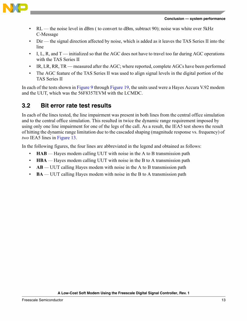
3.2 Bit error rate test resultsIn each of the lines tested, the line impairment was present in both lines from the central office simulation and to the central office simulation. This resulted in twice the dynamic range requirement imposed by using only one line impairment for one of the legs of the call. As a result, the IEA5 test shows the result of hitting the dynamic range limitation due to the cascaded shaping (magnitude response vs. frequency) of two IEA5 lines in Figure 13.
In the following figures, the four lines are abbreviated in the legend and obtained as follows:
• HAB — Hayes modem calling UUT with noise in the A to B transmission path
• HBA — Hayes modem calling UUT with noise in the B to A transmission path
• AB — UUT calling Hayes modem with noise in the A to B transmission path
• BA — UUT calling Hayes modem with noise in the B to A transmission path
A Low-Cost Soft Modem Using the Freescale Digital Signal Controller, Rev. 1
Freescale Semiconductor 13

Conclusion — system performance
In each test, from Figure 9 through Figure 19, the line specified, such as EIA1, was used for both directions of tranmission.
Figure 9. EIA1 line
EIA1
-8
-7
-6
-5
-4
-3
-2
-1
0
9 10 11 12 13 14 15 16 17
SNR dB
log
10
BE
R HAB
HBA
AB
BA
A Low-Cost Soft Modem Using the Freescale Digital Signal Controller, Rev. 1
Freescale Semiconductor14
Conclusion — system performance
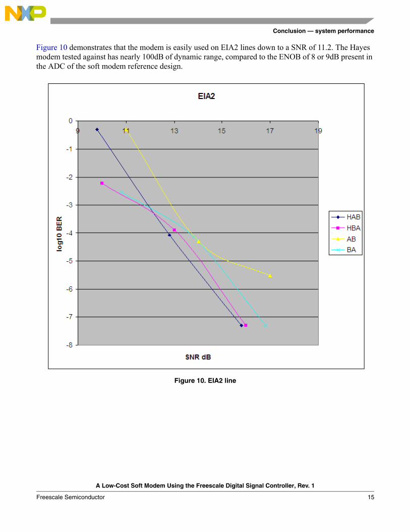
Figure 10 demonstrates that the modem is easily used on EIA2 lines down to a SNR of 11.2. The Hayes modem tested against has nearly 100dB of dynamic range, compared to the ENOB of 8 or 9dB present in the ADC of the soft modem reference design.
Figure 10. EIA2 line
A Low-Cost Soft Modem Using the Freescale Digital Signal Controller, Rev. 1
Freescale Semiconductor 15

Conclusion — system performance
The pair of EIA3 lines is usable down to 12dB SNR.
Figure 11. EIA3 line
A Low-Cost Soft Modem Using the Freescale Digital Signal Controller, Rev. 1
Freescale Semiconductor16

Conclusion — system performance
EIA4 is usable down to 12dB SNR.
Figure 12. EIA4 line
A Low-Cost Soft Modem Using the Freescale Digital Signal Controller, Rev. 1
Freescale Semiconductor 17

Conclusion — system performance
In the worst case for this modem, the EIA5 line is usable down to 13dB SNR. After that, the spectral shaping of the pair of EIA5 lines used in the test exceeds the dynamic range of the unit under test, so the signal cannot be reconstructed below 13dB SNR.
Figure 13. EIA5 line
A Low-Cost Soft Modem Using the Freescale Digital Signal Controller, Rev. 1
Freescale Semiconductor18
Conclusion — system performance
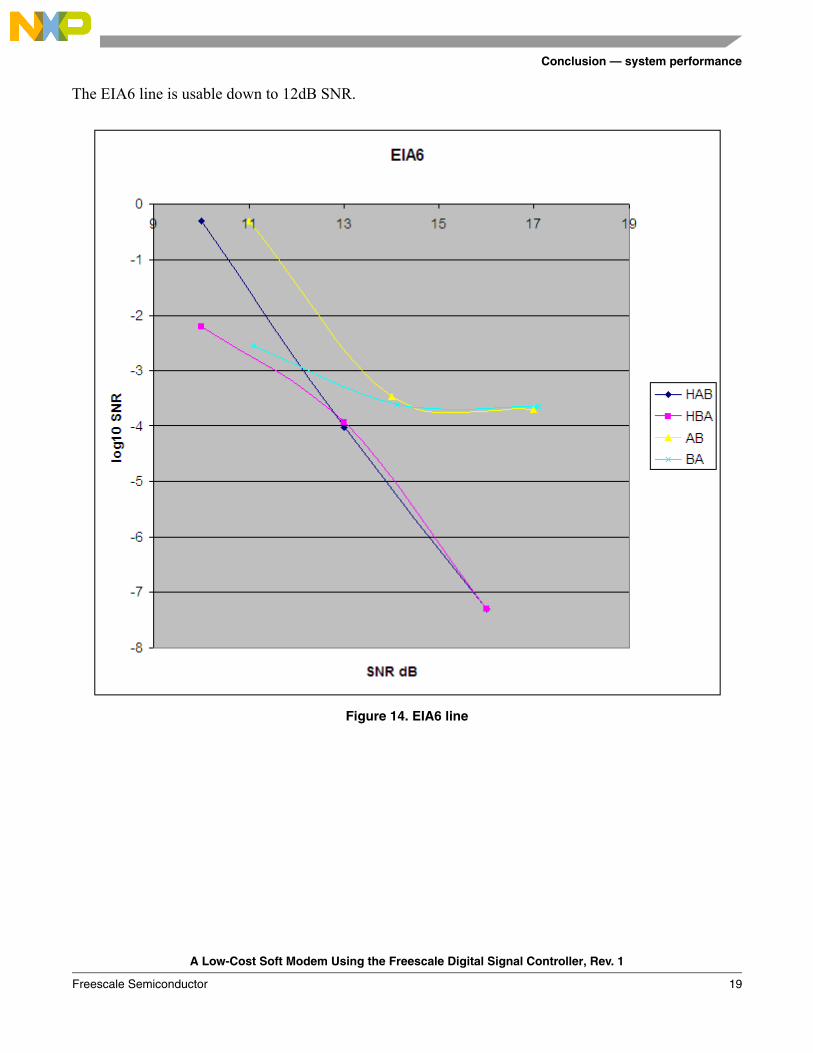
The EIA6 line is usable down to 12dB SNR.
Figure 14. EIA6 line
A Low-Cost Soft Modem Using the Freescale Digital Signal Controller, Rev. 1
Freescale Semiconductor 19

Conclusion — system performance
The EIA7 line is usable to slightly less than 13dB SNR.
Figure 15. EIA7 line
A Low-Cost Soft Modem Using the Freescale Digital Signal Controller, Rev. 1
Freescale Semiconductor20

Conclusion — system performance
The ETSI1 line is good down to 11.5dB SNR.
Figure 16. ETSI1 line
A Low-Cost Soft Modem Using the Freescale Digital Signal Controller, Rev. 1
Freescale Semiconductor 21

Conclusion — system performance
The ETSI2 line is good down to 11.4dB SNR.
Figure 17. ETSI2 line
A Low-Cost Soft Modem Using the Freescale Digital Signal Controller, Rev. 1
Freescale Semiconductor22

Conclusion — system performance
The NULL line was good down to 12dB SNR. The region of interest is where the log10 BER is -3.
Figure 18. Null line
A Low-Cost Soft Modem Using the Freescale Digital Signal Controller, Rev. 1
Freescale Semiconductor 23
Conclusion — system performance
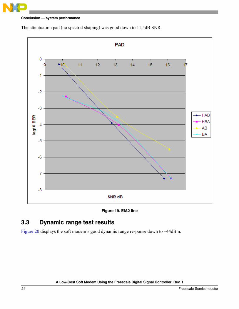
The attentuation pad (no spectral shaping) was good down to 11.5dB SNR.
Figure 19. EIA2 line
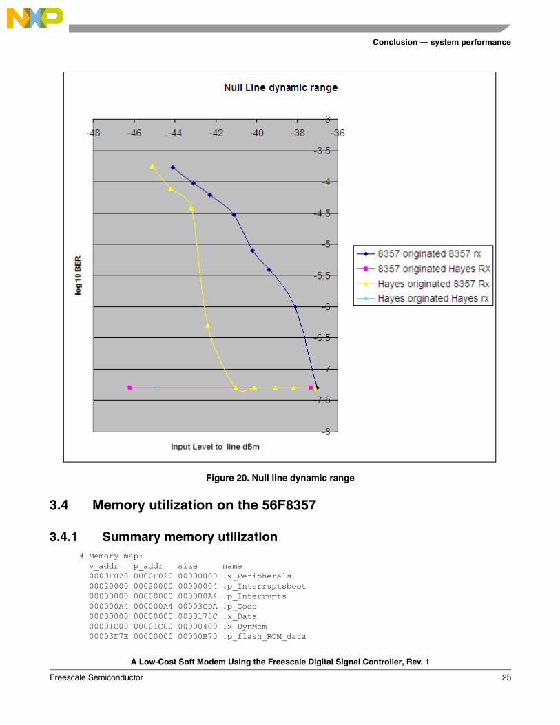
3.3 Dynamic range test resultsFigure 20 displays the soft modem’s good dynamic range response down to –44dBm.
A Low-Cost Soft Modem Using the Freescale Digital Signal Controller, Rev. 1
Freescale Semiconductor24
Conclusion — system performance
Figure 20. Null line dynamic range
3.4 Memory utilization on the 56F8357
3.4.1 Summary memory utilization# Memory map: v_addr p_addr size name 0000F020 0000F020 00000000 .x_Peripherals 00020000 00020000 00000004 .p_Interruptsboot 00000000 00000000 000000A4 .p_Interrupts 000000A4 000000A4 00003CDA .p_Code 00000000 00000000 0000178C .x_Data 00001C00 00001C00 00000400 .x_DynMem 00003D7E 00000000 00000B70 .p_flash_ROM_data
A Low-Cost Soft Modem Using the Freescale Digital Signal Controller, Rev. 1
Freescale Semiconductor 25

Conclusion — system performance
00002000 00002000 00000070 .x_internal_ROM 0002F800 0002F800 00000800 .p_internal_RAM
3.5 Core processor loading and RTOSSince the modem uses almost none of the core processor’s resources, an RTOS may be used to run several tasks along with the modem task.
3.5.1 Core processor load
When the modem is idle, waiting for a call, it consumes almost no MIPS, because the hardware is used to count ring pulses without the help of the core. The core is interrupted only when a significant ring is detected.
The V.22bis bean methods with a line rate of 2400 characters per second are called to recieve data for a consumption rate of 6.21 MIPS. The V.22bis bean methods for transmission of data consume .94 MIPS, so the total MIPS for V.22bis is only 7.15. This is merely a small fraction of the MIPS available on the 60 MIP controller, just over 10 percent.
The fraction consumed is even less when V.21, with a line rate of 300 characters per second is used. The V.21 receiver takes only 1.2516 MIPS. The transmitter takes even less at .1134 MIPS, or much less than one percent of the MIPS available. The total MIPS for V.21 adds up to only 1.364 MIPS, or about 2 percent of the processor’s available MIPS.
3.5.2 Using RTOS to run modem concurrently with other tasks
In order to blend other tasks with the modem, it is advisable to use a real-time operating system (RTOS). A multi-tasking, context-switching RTOS could be used to share the remaining resouces with other tasks, such as alarm monitoring or process control. The modem code itself would be one task, since it is written as one thread.
There are several ready sources for RTOS, including CodeWarrior, Unicoi, and Micrium. Details about Micrium’s RTOS may be found at: http://www.ucos-ii.com/. CodeWarrior includes a demonstration project showing how this RTOS is to be used. Once the RTOS files are obtained from Micrium, they are simply inserted into the code directory, and this demostration project may be run and applied to the modem code.
With the RTOS, the modem code would be made into a task, which would sleep while it is waiting for IO to complete, freeing and unlocking the CPU for other tasks.
3.6 Peripheral footprint The total resource utilization is summarized in Figure 21. This resource load meter is a convient feature of CodeWarrior with Processor Expert. As the project is developed, resource utilization is easily tracked as beans are added.
A Low-Cost Soft Modem Using the Freescale Digital Signal Controller, Rev. 1
Freescale Semiconductor26

Conclusion — system performance
Figure 21. Soft modem peripheral footprint
The small percentage of peripherals used by the modem is depicted in Figure 22. This also shows how the beans are grapically associated with pins on the device. Pins without such associations are free for use in other tasks. Each bean has a unique grapic icon that is easily associated with the pins in Figure 22.
A Low-Cost Soft Modem Using the Freescale Digital Signal Controller, Rev. 1
Freescale Semiconductor 27

Conclusion — system performance
Figure 22. Soft modem pin utilization
3.7 ConclusionsThe soft modem developed is suitable for incorporation into commercial products requiring communication over the Public Switched Telephone Network (PSTN) at speeds up to 2400 bits per second. A traditional telephone codec is not required in the design, resulting in a one-chip/one-core system capable of a complete mission, including communications functions.
Both V.21 and V.22bis/V.22 are supported. The V.22bis falls back to V.22 when noise dictates.
The modem is easily added to projects developed for the Freescale 56F8300 family.
A Low-Cost Soft Modem Using the Freescale Digital Signal Controller, Rev. 1
Freescale Semiconductor28

References
4 References• Freescale 56F8300 Peripheral User Manual, 56F8300UM
• 56F8367 Evaluation Module User Manual, Freescale, MC56F8367EVMUM
• TAS Series II Plus Telephone Network Emulator Operations Manual, 2700-2003, Version 2.40
• TAS Series II Telephone Network Emulator UCO Option Operations Manual, 2700-2734, Version 1.20
• TAS 240 Voiceband Subscriber Loop Emulator Operations Manual, 2700-2397, Version 1.20
• Understanding Telephone Electronics, SAMS, Seventh printing 1987
• ITU-T Recommendation V.22 bis, 2400 Bits Per Second Duplex Modem Using The Frequency Division Technique Standardized For Use On The General Switched Telephone Network And On Point-to-point.
• ITU-T Recommendation V.21, 300 Bits Per Second Duplex Modem Standardized For Use On The General Switched Telephone Network.
• ITU-T Recommendation V.25, Automatic Answering Equipment and General Procedures for Automatic Callling Equipment on the General Switched Telephone Network, Including Procedures for Disabling of Echo Control Devices for Both Manually and Automatically Established Calls
• Measuring The Peak-to-average Power Of Digitally Modulated Signals, Charles J. Meyer, Senior Applications Engineer, Boonton Electronics, Application Note AN-50, 1 Apr. ‘93.
• CH1837A/7F/8A Data Access Arrangement Module Data Sheet, V.34bis High Speed DAA Module, Cermetek Microelectronics
To provide the most up-to-date information, the revision of our documents on the World Wide Web will be the most current. Your printed copy may be an earlier revision. To verify that you have the latest information available, refer to www.freescale.com or contact your Freescale representative.
A Low-Cost Soft Modem Using the Freescale Digital Signal Controller, Rev. 1
Freescale Semiconductor 29

Layout and government certifications
Appendix A Layout and government certifications
A.1 Design for performanceLayout considerations for the PWM are easy. Since it is a digital signal, it can tolerate considerable noise, and layout considerations are few. The ADC however, is an analog input to the controller. It should not parallel at close range signals containing clocks or signals that change often. Stripmine-type shielding could be considered. Please refer to Freescale FAQs and application notes relating to optimal use of the ADC. The layout of the EVM may be used as an example, even though it is possible to reduce the noise floor even further. Given the dynamic range available, this is not required to obtain the performance documented in this note.
A.2 Design for agency approvalsThe final step in bringing a product containing a soft modem to market involves obtaining the approval of and certification by the various government agencies regulating the sale of products that are to be connected to the PSTN. In some countries, the same agency that regulates the post office also regulates the modem product industry. In the United States, FCC part 15 and part 68 should be met and UL approval of any electrical appliance is advised.
The government is concerned with several factors:
• The ability of the equipment to operate in the presense of radio frequency interference
Governments dislike receiving numerous complaints about radio frequency interference. The more a product can be exposed to radio frequency interference without faltering, the better the government’s view of the product.
• The amount of radio frequency interference produced by the product
Certain frequencies are used by government agencies; these frequecies are monitored most closely for compliance. For example, 75 megahertz is allocated to aeronautical radionavigation. If a product broadcasts on that frequency, planes could be endangered.
• The effect of high voltages from tip and ring (including lightning strikes) on the product’s viability and safety
In the interest of consumer safety and product salability, the product should not be destroyed, and any damage should be limited, when lightning or other high-voltage sources come down the tip and ring from the phone pole. The idea is to limit the damage to the parts of the product called the Data Access Arrangement (DAA), when lightning strikes, or when power lines become tangled with phone lines. The ring voltage itself is considered high voltage and dangerous.
• The propensity of the product to become a nuisance by repeatedly calling wrong numbers in the middle of the night to private homes
With the advent of the FAX machine and computer bulletin board, a disturbing trend began. People were called repeatedly by modems or FAX machines. Some countries require “blacklisting” certain numbers and limiting the number of times other numbers may be called per unit time. In order to comply with this requirement, firmware must be tested by government agencies or their designated agents.
A Low-Cost Soft Modem Using the Freescale Digital Signal Controller, Rev. 1
Freescale Semiconductor30

Layout and government certifications
One of the factors simply requires software that cannot automatically and repeatedly dial phone numbers. The radio frequency issues are dealt with by shielding (u metal) and/or minimizing current loop size. Current loop minimization is a layout technique where the open area of a current loop is minimized.
The other factors can be dealt with by selecting a DAA that meets the standards of multiple governments, such as the one selected for this design. Additionally, the area of the product’s PC board where this DAA device is mounted requires special layout attention.
The layout should minimize the area of current loops, or enclose them in shielding, and isolate the high voltage section of the DAA on a one- or two-layer section of the board, well fused from the tip and ring, and located at the extreme boundary of the product.
The current loop area is minimized by running the return wire from any circuit next to, or above or below the source wire for the circuit. It is also good to surround these “wires” or traces with ground plane on as many sides as possible.
NOTEThis reference design has not been examined by government authorities for compliance, but is only used on equipment that simulates the PSTN. Any products developed to be sold to the public would require the respective government agency approvals prior to sale in the respective country and use on the PSTN.
A Low-Cost Soft Modem Using the Freescale Digital Signal Controller, Rev. 1
Freescale Semiconductor 31

Document Number: AN3114Rev. 103/2011
How to Reach Us:
Home Page:www.freescale.com
Web Support:http://www.freescale.com/support
USA/Europe or Locations Not Listed:Freescale Semiconductor, Inc.Technical Information Center, EL5162100 East Elliot RoadTempe, Arizona 85284+1-800-521-6274 or +1-480-768-2130www.freescale.com/support
Europe, Middle East, and Africa:Freescale Halbleiter Deutschland GmbHTechnical Information CenterSchatzbogen 781829 Muenchen, Germany+44 1296 380 456 (English)+46 8 52200080 (English)+49 89 92103 559 (German)+33 1 69 35 48 48 (French)www.freescale.com/support
Japan:Freescale Semiconductor Japan Ltd.HeadquartersARCO Tower 15F1-8-1, Shimo-Meguro, Meguro-ku,Tokyo 153-0064Japan0120 191014 or +81 3 5437 [email protected]
Asia/Pacific:Freescale Semiconductor China Ltd.Exchange Building 23FNo. 118 Jianguo RoadChaoyang DistrictBeijing 100022 China +86 10 5879 [email protected]
For Literature Requests Only:Freescale Semiconductor Literature Distribution Center1-800-441-2447 or 303-675-2140Fax: [email protected]
Information in this document is provided solely to enable system and software implementers to use Freescale Semiconductor products. There are no express or implied copyright licenses granted hereunder to design or fabricate any integrated circuits or integrated circuits based on the information in this document.
Freescale Semiconductor reserves the right to make changes without further notice to any products herein. Freescale Semiconductor makes no warranty, representation or guarantee regarding the suitability of its products for any particular purpose, nor does Freescale Semiconductor assume any liability arising out of the application or use of any product or circuit, and specifically disclaims any and all liability, including without limitation consequential or incidental damages. “Typical” parameters that may be provided in Freescale Semiconductor data sheets and/or specifications can and do vary in different applications and actual performance may vary over time. All operating parameters, including “Typicals”, must be validated for each customer application by customer’s technical experts. Freescale Semiconductor does not convey any license under its patent rights nor the rights of others. Freescale Semiconductor products are not designed, intended, or authorized for use as components in systems intended for surgical implant into the body, or other applications intended to support or sustain life, or for any other application in which the failure of the Freescale Semiconductor product could create a situation where personal injury or death may occur. Should Buyer purchase or use Freescale Semiconductor products for any such unintended or unauthorized application, Buyer shall indemnify and hold Freescale Semiconductor and its officers, employees, subsidiaries, affiliates, and distributors harmless against all claims, costs, damages, and expenses, and reasonable attorney fees arising out of, directly or indirectly, any claim of personal injury or death associated with such unintended or unauthorized use, even if such claim alleges that Freescale Semiconductor was negligent regarding the design or manufacture of the part.
For information on Freescale’s Environmental Products program, go to http://www.freescale.com/epp.
Freescale™ and the Freescale logo are trademarks of Freescale Semiconductor, Inc. All other product or service names are the property of their respective owners.© Freescale Semiconductor, Inc. 2005, 2011. All rights reserved.