a lightweight and self-contained airborne navigational system
TRANSCRIPT

PROCEEDINGS OF THE IRE
A Lightweight and Self-Contained AirborneNavigational System
R. K. BROWNt, N. F. MOODYt, P. M. THOMPSONt, R. J. BIBBYt,C. A. FRANKLINt, J. H. GANTONt, AND J. MITCHELLI
Summary-The paper discusses the design of a self-containednavigational aid for aircraft. There are many techniques and vari-ations upon which such a system may be based. The one chosen fordiscussion is a hybrid system which combines an inertial north refer-ence, a Doppler navigational radar, and an airspeed indicator. Avelocity triangle computer relates these three sources of input data,so that the airspeed indicator may fill in when there is no radar signal.The output of these instruments, track angle and distance, is fed toa positional computer and thence to a steering computer, so that bothpositional and steering information may be supplied to the pilot.
Part I introduces the general problem of a self-contained navi-
gational aid, the possible sources of input data, the usual frames ofreference within which aircraft position may be stated, and theforms of route to a destination which may be derived. Part II de-scribes an FM Doppler radar as part of an over-all navigational sys-tem, and Part III the circuit implementation of the radar, based ontransistors. Part IV describes a converter for connecting the radar toan analog positional computer, and some velocity vector trianglecomputers. Part V discusses a digital form of positional computerand some of the necessary digital processes. The paper concludeswith Part VI, which presents the problem of steering computationand some ideas on the implementation of a complete system.
Part I-An Introduction to Aircraft NavigationP. M. THOMPSON, N. F. MOODY, AND R. K. BROWN
T HROUGHOUT the history of navigation, it hasbeen the usual practice for navigators to carrytheir equipment with them. Such is still the case
at sea, but in the air there has been the opposite tend-ency, so that today most airborne navigation is bymeanis of radio aids which depend upon surface stations.The cause of this trend is that the earlier aircraft wereun-able to carry anything but the simplest radio equip-m-fient and were forced to rely upon these surface station-sto mleasure their position for them. Historically this hasled to the many sophisticated land-based radio naviga-tioinal aids today. However, there are large parts of thesurfacce of the earth, such as the Canadian Arctic, stillniot covered by these aids. Furthermore, in time of wartheir use nmight well be denied the navigator siiice theywould be subject to jamnming, or could be of equal useto an enemy.There is a requirenIie-it, then, for a self-contained air-
borine navigational aid, capable of operating any' Thereover the surface of the earth at anly time and utider anyconditions. Such an aid must be light in weight as, al-though it is now possible for an aircraft to carry heavyloads, anly unnlecessary weight represents a reduction inpavload aind may thus reduce the efficiency of the air-craft by a prohibitive amount.The process of navigatiion of an aircraft consists essenl
tially of discovering its position, and then-i determiniiinga route to its destinationi. It is impossible to define aposition without referrinig to its surroundings, since nropoin-t can be defined by referenice to itself; so an external
* Original maniuscript received by the IRE, February 12, 1959.This project was done uniider the authoritv of the Defence Res. Boardof Canada.
t Defenice Res. Telecommuin. Est., Ottawxa, Ont., Cani.I Linik Aviation, Binghamtoti, N. Y.; formiierly with Defense Res
Telecomt--imun. Est., Ottawa, Ont., Can.
frame of reference suitable for the determiniation of therelative positions of aircraft and destination is necessary. The function of an aircraft navigation system-,then, is to collect available data on the aircraft's prog-ress, to place it withini some frame of reference, atndfinally to compute a route to its destination.'
There are several sources of data which might besuitable for such a navigational aid. lagnetic devicesor inertial devices could be used as a directional reference or compass. Positioii- could be given by terrestrialor astronomical map reading, or could be coml-putedfrom directioni and speed (or distance) giveni by radaror airspeed indicators. Also, speed may be given in-directly by inertial devices which measure acceleratiols.
Fuller discussion follows of these sevei-al sources ofdata. In assessing their relative suitability as ntavigational aids, it is necessary to intiroduce a criterion whichbecomes more important as aircraft speed, and also accuracy of navigatioin, increases. In general, positional in-i-formation, within a frame of reference suitable for navi--gation, is obtained as a result of some interpretative orconversion process on the input data. The process in-volves some time delay, so that the resultatit infioria-tion- is available only in retiospect. Present positioni,thlerefore, is based upon- a predictioni. Hence accurateiavigatioii requires that the aids should yield datapromptly in a form suitable for rapid conversion processes.
1) \lMagnetic and inertial heading refereiices: Mag-netic compasses will provide a headinig referenice usefulat low geomagnetic latitudes. However their inidlicationsare disturbed in the vicilinty of imnagnetic bodies, partkicu-
1 W. R. Fried, "Principles amtd performiiance analysis of Dopplernavigation system," IRE TRANS. ON A[ERONAUTICAL AND N\-vIGATIiONELECTIRONICS, vol. ANE-4, pp. 176-196; December, 19957.
778 May

Brown, et al.: A Lightweight and Self-Contained Airborne Navigational System
larly near the poles, where it is usual to rely upon in-ertial devices.
2) Terrestrial and astronomical map reading: Navi-gation by map readin-g consists in identifying points onthe ground, or in the sky, with points on a map; itssuccess depends equally oii being able to see andpossessing an adequate map. Seeing is not limited to thevisual spectrum, and radio wavelengths may be useful.Terrestrial map reading may be assisted by such radarsas H2S, which remove the limitations of normal visionsince the aircraft carries its own source of illumin-ationwhich can penetrate weather and darkness. Astronavi-gation by radio stars is still limnited by the present stateof developmenit of radio receivers. Visual methods arelimited by speed of interpretation, weather and time ofday. In the Arctic regions the twilight period, when it isimpossible to see either the sun or the stars, may last formany hours and often for a whole flight. When it ispossible to see the stars, there are many suitable maps,but there are still parts of the earth not adequatelymapped, and maniy places such as the sea or the Arcticwhere there are few, if any, idenitifiable points.
3) Doppler navigational radar1 8: Radar, using theDoppler shift in signals scattered back from the grouind,gives ground speed (or distance) directly and appearscapable of providing a useful output anywhere over thesurface of the earth.
4) Airspeed indicator: An aircraft may be navigatedwith respect to the air mass through which it flies, usingtrue airspeed and a directionial reference. Informationabout the movement of this air mass canl be provided byground stations and used to compute the progress of theaircraft with respect to the ground.
5) Inertial devices: Acceleration sensitive devicesalone will provide sufficienit information for an. aircraft'sprogress to be measured. However such completely in-ertial systems are very expensive, and it is economicalto use inertial devices only to provide a directional ref-erence.A system based on a combination of these sources of
input will permzit an aircraft's progress to be measuredcontinuously with an accuracy and stability high enoughfor most purposes. However, a navigator must know hisposition within a frame of reference. The four types ofreference most commonly used are:
2 E. G. Walker, "Factors in the design of airborne Doppler navi-gation equipment," J. Brit. IRE, vol. 18, pp. 425-442; July, 1958.
3 F. B. Berger, "The nature of Doppler velocity," IRE TRANS. ONAERONAUTICAL AND NAVIGATIONAL ELECTRONICS, vol. ANE-4, pp.103-112; September, 1957.
4 F. B. Berger, "The design of airborne Doppler velocity meas-uring systems," IRE TRANS. ON AERONAUTICAL AND NAVIGATIONALELECTRONICS, vol. ANE-4, pp. 157-175; December, 1957.
5 M. W. McKay, "The AN/APN-96 Doppler radar set," 1958IRE NATIONAL CONVENTION RECORD, pt. 5, pp. 71-77.
6 T. Gray and J. Moran, "Decca Doppler and airborne naviga-tion," Brit. Commun. and Etectronics, vol. 5, pp. 764-771; October,1958.
7F. A. McMahon, "The AN/APN-81 Doppler navigation sys-tem," IRE TRANS. ON AERONAUTICAL AND NAVIGATIONAL ELEC-TRONICS, vol. ANE-4, pp. 202-211; December, 1957.
8 M. A. Condie, "Basic design conlsiderations-Automatic navi-gator AN/APN-67," IRE TRANS. ON AERONAUTICAL AND NAVI-GATIONAL ELECTRONICS, vol. ANE-4, pp. 197 201; December, 1957.
1) Latitude and longitude: A latitude and longitudereference is universal and unique and finds its major ap-plication where aircraft must fly long distances, andwhere a pilot or navigator wishes to communicate hisposition with widely spaced centers, perhaps under dif-ferent administrations. However, it becomes difficult touse near the poles, where special "square" grids are inuse.
2) "Square" grid: Reference grids, which are closespherical approximations to the rectangle, are in useover nmost of the populated regions of the earth, as wellas at the poles. They constitute a fairly simple methodof representing position, whenever the aircraft remainsill the area covered by a single grid.
3) Track and bearing: Giving position in relation to adesired track is a very simple system. Position, statedas a distance along and across this track, finds applica-tion in flying along air lanes. The bearing system isoften used when the position of an aircraft operatingfrom one station is stated as a range and a bearing fromthat station.
4) System references: Many ground-based radio navi-gation systems such as Decca, Dectra, Loran, Shoran,and Gee indicate position on their own system of curvedcoordinates. For an important traffic lane, these curvedcoordinates are sometimes made to approximate a greatcircle by careful siting of stations.Once present position and destination are knrown in the
desired system of reference, steering information mav becomputed. The steering information required usuallyis the bearing on which to fly, and the approximate dis-tance so that the fuel requirements may be computed forthe flight. The bearing is usually required as a greatcircle or close approximnation, a rhumb line,9 or with ref-erenice to an air lane.A discussion of a complete navigationi system follows.
First the sources of input data are described, followedby techniques for computing position, and thence bysteering information. Only automatic computing tech-niques are discussed, since in modern aircraft the navi-gator has insufficient time to make the computationsunaided.
A. AN OUTLINE OF THE SYSTEM DESIGN
A convenient and economical design (Fig. 1) usesinput data conisisting of direction and speed of flight.The heading10 of the aircraft is provided by an inertialheading reference, and when heading is added to thedrift angle1' this gives track.'2 Information from whichspeed and drift angle may be computed is available fromtwo sources: a Doppler navigational radar and an air-speed indicator, The computation of ground speed from
9 Rhumb line, a line between two places on the surface of theearth, which maintains a constant bearing with true north.
10 Heading, angle between datum line of aircraft and a referencedirection (north oin a latitude-longitude system).
11 Drift, angle between aircraft datum and actual direction offlight.
12 Track, angle between direction of flight and reference direction.
1959 779

780 PROCFEDIZVGS OF TIHE [RE
DESTINATION
Fig. I The over-all navigational system consistilig of the followixig.1) Input organs: north referenice, Doppler n-avigational radar, andairspeed indicator. 2) Computers: velocitv trianigle compuiter,positional conipnter, anid steerinig computer,
true airspeed, and winld speed and directioni, is per-formed by a velocity triangle computer, which alsocomputes track from drift and heading. Ground speedand drift are also giveil directly by the radar. Note, atthis stage, that the radar provides speed as an outputwaveform whose frequency is such that onie cycle rep-resenits utnit increment of distance. While the radar mraytherefore yield direct distance injformation, the systemmay be understood more readily if the output of theradar is considered as representinig groun-d speed.
This part of the systemn is capable of operating ineither of two modes: the Doppler mode, when ttie radarprovides ground speed and drift angle directly, and thevelocity triangle computer provides track from headingand drift angle; and the meimory mode, when thevelocity triangle computer uses stored wind data, trueairspeed, and heading to compute track and ground
speed. Wheni the system is switched on wxith the aircraftstaniding oni the grounid, there wxill be no output fromthe radar, and the system will be in its m;iemlory niode(xxwith the wind data set by hanld). As soon- as the radai-obtains a usable signal, usually just onl leaving the runway, the system switches to the Dopplte inode andthereafter calculates witid conlitiuously. ShouldL theDoppler signal fail due to aircraft attitude, or for anyother reason, the systemn xvill switch to mieniory anid usethe last computed wind.The north referenice, radar, airspeed indicatol and
triangle are coniiected iin suLch a way that the groutndspeed (or distance) output is froml- the radar, and thetrack angle output is fromi the velocity triangle coin}1puter. A positional computer uses these two outputs,together with a preset starting positioif, to cor-iputeposition- continuously during flight.A steering computer, in turn, uses this calculated posi-
tion to determine a route to a preset destination. The ini-formiiation from all three cormputers may be displayed.as required, or used in connection with such devices asan automatic pilot to conitrol the aircraft.
Certain of the following sectionis of this paper describe in detail the Doppler racdai, which is the heart ofthe system. Maniy of the circuits are discuissed, and,since weight is at a premium and reliability is of paia-mount importarnce, transistors are a natural choice forthe active devices. The sectionis on: computationial tech-niques do not present any single system, since the requiremernets will vary with application The headin-greference and the airspeed indicator are outside the scopeof this paper, and are niot described.
Part 11-The Principles and Performance of the Doppler RadarR. K. BROWN
The purpose of the i-iavigational radar within theover-all navigation-al systemi (Fig. 1) is to measure air-craft ground speed (or distanice tra-veled over the surfaceof the earth) and drift angle. This part of the papertreats the radar as part of a system, describing theprinciples by which it operates and the measured per-formance. The separate circuits will be treated inPart III.The principle by which the radar operates is based
upon the Doppler shift of a miicrowave signial tranis-mitted from the aircraft and scattered back from theground at a poinit either ahead of or behind the aircraftFig. 2 shows an aircraft traveling over the surface of theearth. First coinsider a single microwave beam, directedforward from the aircraft to strike the ground at A [Fig.2(a) ]. A receiver located at A otn the ground would receive a signal shifted in frequency from that of thetransmiitter in the aircraft due to the Doppler effect.The frequenicy shift, fd', is givetn by
fdFVV cos
(1)
wheiefJa= Doppler frequency,F transmriitter frequency,c propagation velocity of electrotn-iagaetic radia-
tion,V,= ground speed of aircraft,
= angle between the aircraft's direction of flightand the direction of the transimitted signial.
If some of the energy striking the groutnd at A isscattered back to the aircraft, the siginal, as received atthe aircraft, suffers a second Doppler shif-t exactly equalto the first. The total change in frequency as observedat the aircraft and called the Doppler frequenicy, fd, isgiven by
2FV cos cfd 2fd (2)
780 -May

Brown, et al.: A Lightweight and Self-Contained Airborne Navigational System
AIR SPEED 451 KNOTSGROUND SPEED 440 KNOTSALTITUDE 20,000 ft.TRANSMITTER 60 mW
2 3 4 5 6
DOPPLER FREQUENCY kc
(a)
st-z
n:I-1In
ci:
(b)Fig. 2-Doppler navigational beam structure. (a) A single forward
beam. (b) The four beams of the practical radar.
AIR SPEED 396 KNOTSGROUND SPEED 361 KNOTSALTITUDE 20,000 ftTRANSMITTER 60 mw
h,,t,10 12 14
kc2 4 X a
DOPPLER FREQUENCY
(b)
In practice, because of the finite width of the beam'and the uneven nature of the ground, the Doppler re-
turn is iiot a single frequency but a nloise spectrum ap-proximately Gaussian in shape, whose width dependsprimarily upon the beamwidth. A typical spectrum is
shown in Fig. 3(b).If (2) is rearranged to make Vq the independenlt vari-
able and if, further, both sides are integrated, we obtainthe distance R which the aircraft has traveled. Thus
n2\
R = 2 I(2a)2 cos
where n = number of Doppler cycles and X wavelength
of the transmlitted signal.It is seen that the distance flown may be determined
by simply counting the total number of Doppler cycles.In practice, the frequency counted in such a system isthat of an oscillator in the tracker whose function is toprovide a highly accurate representation of the meanlDoppler frequenicy. (Reference will be made later tothis element, which for clarity, will be called the trackeroscillator.)
In order to determine the aircraft drift angle, the twoforward beams A and A' of Fig. 2(b) are substituted forthe single beam. If the aircraft velocity vector is notalong heading, i.e., drift exists, the Doppler shifts forthe two beams will not be the same. This information isused via a suitable servoloop to rotate the alntenna sys-tem in azimuth until the Doppler frequencies obtainedfrom the two beanms beconme equal. When this has beendone, the axis of symmetry of the antenna system hasbeen aligned with the ground track of the aircraft, andthe angle between this axis and the aircraft heading de-fines the drift angle.
AIR SPEED 399 KNOTSGROUND SPEED 349 KNOTS
ALTITUDE 40,000 ft.z TRANSMITTER 60 mW
0 2 4 6 8 to 12 14
DOPPLER FREQUENCY kc
(c)
Fig. 3-Measured spectra of Doppler radar return signals. (a) Anunusable spectrum obtained when Lusing a single beam. (b) Aspectrum obtained under similar conditions to (a) when uisitig bothfore and aft beams. [The peak at approximately 8 kc wouild cor-respond with a peak at 4 kc in (a). (C) A spectrum which illus-trates that a l0-db SNR is obtainable when iAsing a 60-mwklystron- at 40,000 feet.
Fig. 2(b) also shows a rearwardL beam correspondingto each forward beami (C with A and C' with A'). Thetwo pairs of beam-s are time-shared, C and A being on
together for abotut 0.5 second, followed by C' and A'
for 0.5 second. The instantaneous sums of the Dopplershifts on beanms C and A and C' and A' are now avail-able. It will be shown that the substitution of two pairedbeams for two single beams results in considerable im-provement in accuracy.
The use of such paired beams produces a system re-
ferred to as a Janus system, after the Roman god wholooked forward anid backward at the same time. Threeimportant advantages result from the use of such a
techinique:1) The error introduced by any vertical component
of aircraft velocity is completely eliminated.2) The ground speed error due to variations in the
angle caused by pitch movement of the antenna isgreatly reduced. From (2) it is seen that fd is propor-
tional to cos b. With the values of 0, used in most
0
zw
(0IJW
:x
(a)
7811959

PROCEEDINGS OF THIE IRE
MICROWAVE DETECTOR
Fig. 4-A simplified block diagram of the Doppler radar system. (Several auxiliary parts of the systema-are omitted in the initerests of clarity.)
Doppler navigation radars, a small change in 0 producesa fairly large change in fd. For example, for the systemto be described a single beam develops a 1 per cent errorfor an 11 minute change in 0. However when two beamrsare used, 4$ can change by nearly 10° before a 1 per centerror develops. Antenna pitch stabilization requirements are therefore much less critical with Janus bean-ls,and for some applicatiorns pitch stabilization cani beomitted.
3) There is a first-order correction of Doppler spec-trumi spread due to short-tern-i frequency variation ofthe transmitter itself. If a single beam is used and theDoppler spectrum obtained froni a comparison of thereturin signal from the ground with a signal directlyfrom the transmitter, noise FM\J of the transmittercauses a spread of the spectruni. This blurring of thespectrum increases with altitude and is very serious insome aircraft flying above 30,000 feet. Fig. 3 illustratesthe effect. Fig. 3(a) shows an unusable spectrum ob-taimed wheni using a single beam. The acceptable spectrum of Fig. 3(b) is obtaiiied, under siniilar conditions,when both fore and aft beams are used.
It will be noted that this technique doubles the audiofrequency at which a Doppler signal is observed. Thusthe peak at approximately 8 kc in Fig. 3(b) would cor-respond with a peak at 4 kc in Fig. 3(a). This is treatedin greater detail in Section D of Part II3[
A. THE FAM TECHNIQUE
TIhe Doppler radar developed for this project uses anFM traiismiitter. It is instructive to review briefly thehistory of Doppler development, which reveals thereasoii for this choice. Early systems used search radartechniques with high peak power (kw) and shor-t pulses(! psec with a duty cycle of 1: 1000).7 These were allvery heavy systems of 300 400 pounds weight. TIhequest for lightweight systems led to more efficient use ofthe tran-smitted power. CW systems,8 where both trans-mitter and receiver are on the whole time, theoreticallyoffer the m[ost efficient use of transmitted power. How-ever, such a system reveals serious practical problems.It is difficult to prevent energy fromn leaking directlyinto the receiver and swamping the ground returnl athigh altitudes. The magniitude of the problem m-nay be
appreciated when it is noted that 150 db of receiver iso-lationi are required for operation. at 50,000 feet, It ismore coniveniient to use a system in which a direct leakof transmitter energy into the receiver is unimportant,and this is possible when (as here) the signal retunius aredelayed.Two solutions to this problem which exploit such
time delay and do not involve a great reduction of ef-ficieuicy are the long pulse system,m, where the trans-mitter is on for about one half of the total time, aiid theFM technique.2 The latter method was adopted for theCanadian development because of the ease with whicha klvsti-oii could be modulated and because it requiredno increase in the numiiber of niicrowave operations bycomiparison with the CW system Fig. 4 shows a blockdiagrami of the radar, -which is coniplete except for th-eservo-tunled "tracker oscillator' which produces ahighly accurate representation of the Doppler frequetncv.The system makes use of duplicate anitennD-a channels
A and C, which perforrm the Janus operationi. The signals reaching each microwave crystal mixer consist ota local oscillator signal, which is a sample of the tiaismitted energy, and the Doppler shifted return ffronii th-ieground. Both signals carre a, sidebaind spectrum typicralof FP\4 at 1 mc (Fig 5). The receiver channiel has a passband at 3 mc, and the transmitter modulatiomic inidex isso chosen that the output of the mricrowave mixei hasmaxiniumn possible einergy conce xitration in this bau-d.If the received signal has suffered a tim-ne delay which snegligible conipared with the modulatioii period aswould be the case with transmitter leak via the duplexeror radorne, there is no output from the microwave nmixeat 3 mc, and the system is thus insensitive to such ixoiseHowever, if the received signal has traveled to theground and back and, therefore, has been delayed, therewill be a 3-mc output from the crystal mixers. Thus thesystemi provides receiver isolation which proves to beequivalent to more than 150 db for a duplexer isolationof only 25 db.That the system operates as described above cani be
seen by examining the result of mixing the tranismittedand received signals in a multiplier circuit Let
ei = Eo sin (wi +4M sin pi) (3)
782 .Al'y

Brown, et al.: A Lightweight and Self-Contained Airborne Navigational System
TRANSMITTED
RECEIVED
SIGNALFREQUENCY
3 2 f 2
*(- f-Mc ftMc
Fig. 5-Diagram of a microwave carrier, freqtuency f, frequencymodulated at 1 mc, anid its sidebainds (above). Below is a diagramof the same signal after having received a Doppler shift.
be the transmitted signal, and the form of the local oscil-lator signal and let
e2 = E0 sin [coi(t t1) + sin p(t ti) (4)
be the received signal, where
X= carrier frequency (radians/second),p FAI (radians/second),
frequency deviationAlf = modulat'ion index_ 7
F1F
w,= received frequency (radians/second),-2 range to ground]
t, delay time_ c
Then the difference term in the product (ei Xe2) whichappears at the receiver is
E02
- cos [(cwt + M sin pt)--wi(t-ti)-M sin p(t-t1)] (5)
E02_2 cos [ct-co(t-ts) + M[sin pt-sin p(t-t1)1I (6)2
which, after expansion and rearrangement, becomes
EoS2---Cos t c1( t1)2
+ 2M sin [cos (Pt- -)JJ (7)
Eq. (7) represents an FM signal with a carrier frequency(co-co4)/2r, the same FM as in the transmitted signal,and a modulation index given by 2M sin pt1/2.
It might appear that the system would lose signal ataltitudes correspo'nding to a time delay equal to theFM period. This has not been detected during flightsover land, but recent overwater flights have demon-strated a very high signal attenuation at altitudes cor-
responding to the two lowest predicted "holes." Appar-ently, at higher altitudes the variation in range over thebeamwidth masks such effects.
B. FLIGHT TRIALSA series of flight trials has illustrated that the radar
has sufficient accuracy to be the major input organ fora useful navigation system. This has been done usinigthe system in Fig. 1, with the exception of a steerinigcomputer. The Doppler radar used a 60-mw traiisijiitter,and the positional computer was based on simpleanalog techniques.The trials have demonstrated that two of the objec-
tives have been attained: 1) distance can be measuredreliably to an altitude of at least 40,000 feet and 2) ac-curacies of 0.5 per cent in distance and 0.50 in drift canlbe attained easily.
Fig. 3(c), typical of a number of spectra, is taken witha transmitter power of 60 mnw and shows that a 10-dbSNR is possible at 40,000 feet. The system under con-struction uses a 600-mw transmitter (without any in-crease in size or weight) and this is expected to extendthe operational altitude well above 60,000 feet.The accuracy of the radar has been mieasured over
various surfaces. Extensive measurements have beenmade along a marked course to obtain a reliable measureof the accuracy with which the system measures dis-tance over the ground. The equipment has beeni flownover sections of electric power transmission line, and thedistance as measured by the radar compared with thesurveyed distance. The results of 100 measurementsshow a standard deviation of 0.2 per cent in the distanceflown. It has not been possible to carry out a reliable de-termination of drift angle accuracy since there has beenno sufficiently accurate reference for comparisoln. How-ever, correlation to + 0.50 has been demonstrated bycomparing average drift as measured by Doppler withthe average of a number of drift sight readings taken bya navigator. It is probable that most of the error wascontributed by the navigator and that the radar is con-siderably more accurate. These measurements were allmade over land.Accuracy determination over water has been done
using the same general technique, but with a Decca navi-gation system to provide a mleasured line 80 miles long.Approximately 50 measuremients have been made overthe Atlantic Ocean southeast of Halifax, N. S. All thesemeasurements have shown a significant difference be-tween the distance measured when flying up wind andthat measured flying down wind (reference is to windsat the water surface). The standard deviation of thesemeasurements was 1.5 per cent. Attempts to correct theresults for mIovement of the water due to winds an)dtides reduced the standard deviation onily to 1.0 percent. This is not surprising, since our knowledge of thesurface winds existing at the time of the runs, and ourunderstanding of the effect of wind on water movement,are both sketchIy.Two effects which may cause navigation errors when
flying over water are known.4 One occurs over relativelysmooth water and is due to an increase in specular re-flection of the incident beam. This reduces the strength
1959 783

74PROCEEDINGS OF TFE IRE
of the signal received at the aircraft and possibly favorsthe lower half of the beam. The effective angle of depres-sio3n of the beam (angle q, Fig. 2) may thus be in-creased, producing a ground speed error. An errorof approximately 0.5 per cent has been predictedtheoretically for a beamwidth of 30 T1he existence ofthis phenomenon could not be verified during these tri-als, because at no time was the sea smooth enough, andbecause the second effect, described below, was largeenough to mask it.The second effect is due to actual movement of the
water in mass caused by tides or, at the surface, byw inds Any navigation carried out over such a mediumn,
using Doppler m1easured grouiid speed, will cot taiilai[error determined by the net movement of thek watetiduring flight.
It is proposed to examinie this phenomenoni furttheby correlating more detailed water n-ioveniei;t in-formation xwith the resu1lts of Doppler radar distao:vcemeasurements.From this series of flight trials, it may be concluded
that the radar measures distance over land with anlovei-all accuracy of 0.2 per cent and probably measuresdrift with the same accuracy. However, larger errors areto be expected over surfaces which mav be either siniootli,or movilng, such as water
Part IIIThe Circuit Implementation of the RadarP. M. THOMPSON, N. F. MOODY, C. A. FRANKLIN) AND R J. BIBBY
It will be recalled from Section A of Part II that thenavigational radar is based upon the FIM principle according to the block diagram of Fig. 4. The circuits arenow to be described, with the exception of some auxili-aries not considered of sufficient importance to warrantinclusion.
Apart from the transmitter klystron, no vacuumtubes are used in the instrument to be described: all cir-cuits are based on transistors. The design has beendirected to make the performance insensitive to transis-tor parameter variations, so that the accuracy depeiidsprimarily on passive elements. Every attempt has beenmiade to attain the highest reliability, and to this endthe design is directed to eliminate certaini componeiitsof questionable life, such as electrolytic capacitors.
A THE M\IODULATORThe mnodulator c in Fig. 4 performis two functions. It
generates a 1-mc sinusoidal signal to frequency modu-late the klystroni @ and it provides a 3-mc carrier whichis combined with the IF signal at the detectors® and ®,A circuit fulfilling these requirements consists of a 1-mccrystal controlled square-waave geiierator driving a high-pass and a low-pass filter in parallel. The two filters op-erate in such a way that the low-pass filter selects the1-imc fundamental component of the square wave tomodulate the klystron, while the high-pass filter passesthe remainder of the frequency compon-ents, the strong-est of which is at 3 mc, to feed the detectors.The chief requiremen-ts of the modulator are these:
1) the amplitude of the 1-mnc modulating signal shall beaccunately defined, for uponi this level depends the FMsideband distribution; 2) there shall be a fixed harmonicanid phase relationship between the 1-nric and 3-me sig-nals; and 3) the frequency stability must be such thatthe received signals fall properly within the pass bandof the IF receiver. A coniveiitional LC resonant circuitwould probably provide sufficient stability, but the use
of a quartz crystal permits an extremely simple aiidlightweight circuit of excellent perfor nianee and built-iaccuracy.
Tlhe requirements for accurate amplitude control an dconstant harnionic relatioonship are conveiiiently inet bygenerating a 1-mc square wave, passed through filteirsto provide the necessary output signals. The amplitudeof the I inc fundamental component is defined accu-rately when the square wrave amplitude is defined. Hfirmonic relation-ship between the 1-inc anid the 3-nc out-put is a direct result of their comnmon source.A circuit diagrami of the square wave generator is
shown in Fig. 6, and operates in the followitng miaiinieriThe emitter resistors R2 aind R3 are equal, anid so setequal bias currents in transistors J1 aiid JS The value ofthe emitter current is given by
Ie20 o
(8)
Because (20- V0) is so much greater thami the emitter-base voltage drops of Ji and J2, or the forward voltagesof diodes Di anid D2, the average curreiit of each transmstor is still defined by (8) when the circuit is oscillating.A positive feedback loop exists via the frequenicy con-
trolling crystal X, which connects the collector of J, tothe base of J2, and by neans of the conden-ser Ci whicheffectively provides a short circuit between: emitters atthe frequency of oscillation. At this fumidaniental fre-quency the crystal exhibits series resonaance, and is oflow impedance, while the circuit LC, tutned near thisfundamental, is of high impedance. If the diodes DI andA are ign-iored for the moment, it is seen that the ooloogain is high and oscillatioii will occur. Spurious oscillations, on the other hand, are not possible; for at frequeiicies above or below the fundamental, the reactance ofthe crystal rises, while the tuned circuit imposes simultaneously a shunt, froin the feedback loop to groundc
784 Mav

Brown, et ai.: A Lightweight and Self-Contained Airborne Navigational System
Fig. 6-The circuit diagram of the prime generator of the modulator.(A crystal controlled square wave oscillator.)
tIPNTCHING I m - DERIVED Im -DERIVED LOADSECTION HHALF-SECTION HALF-SECTION
C
Lk t CIL
! 2K
§ ! Ck ! -2Ck ! iII
PRACTICAL CIRCUIT
>--4 I -_---> TO 2K LOAD32.4 SG.
1125HT 226
(a)MATCHING CINSTANT-K tm- DERIVED m-DERIVED LOADSECTION HALF-SECTION I HALF-SECTION i HALF-SECTION
MDLk MLkk) - Ck | 5<t
IT T>~~~~~~TDII DV
The resulting 1-mc oscillation causes the total transis-tor currents [2I1 of (8) ] to commutate between J1 anldJ.1. There results- a 1-mc square wave of current at thecollector of J.2 of peak-to-peak amplitude
2(20 VO)Is = -R---7 (9)
which is accurately defined. Hence an accurately con-
trolled square wave of current will flow in the resistorR, termiinating the filters. It follows that the outputs ofthe two filters also have accurately defined amplitudes.The diodes D1 aind D2 are silicon junction diodes,
whose threshold of forward conduction (-0.6 v) is suf-ficiently large for the transistor commutating action toremnain undisturbed by their presence. The diodes serve
merely to limit the voltage excursions at the base of J2,and also to supply a low-impedance path for any crystalcurrent in excess of its requirements.The filters are complemientary high- and low-pass
units, sharing the comimon source load, R. Their designis illustrated in Fig. 7(a) and 7(b), respectively. Theamplitudes of the respective outputs from these filters,the fundam-iental anid third harmonic, are readily com-
puted from the Fourier expansionl of aln ideal squarewave. Thus the RMS voltage of the fundamental is
2 X 2 R(20- Vo)= X 0.707, (10)
17r R2
which depends only on passive components.The performance of the modulator easily exceeds the
specification demanded by the radar. Within the tem-perature range - 55°C to + 70°C the frequency is stableto within 30 cycles, and the level of the 1-mc output isconstant to within + 1.5 per cent. Third harmonic,which must be rigorously excluded from the 1-mc out-put, is 60 db down. Little attempt is made to remove
harmoonics from the 3-nwlc signal to the niixer, for theseare not harmful.
Since the harmoniic cointent of the oscillator is influ-
PRACTICAL CIRCUITD93 FH 3005H
> TO 2K LOAD
9.35
83.3 T T 3T.4
(b)Fig. 7-The high-pass (a) an-id low-pass (b) filters of the modulator.
enced by temperature, this output is less stable in amn-plitude, but adequate for the purpose required.
B. THE IF AMPLIFIER DESIGN
Three designs for the 3-nic IF amplifier exist. On-iemodel uses germanium alloy transistors whose fl, is ap-
proximately 10 mc, another is based oni surface barriertransistors, and the third uses drift transistors. The de-signs, using both surface barrier transistors and drifttransistors, have undergonie the full series of environ-iniental tests demanded of the over-all equipm-ient. How-ever, the design using drift tranisistors has met the targetnoise-figure specification of 2 db, so this design is de-scribed.The specifications for the IF amplifier call for ani over-
all amplification of approximately 100 db, and a band-width in the order of 100 kc. It will tolerate a tem-perature range from - 55°C to + 700C, and contain pro-
vision for automatic gaini control (AGC). The actualcontrolling circuit, part of the Janus unlit, is called upon
to hold the signal level, at the appropriate poinlt in itscircuit, constant within +5 per cent for variations atthe input of the IF amplifier of 40 db.The amplifier has five stages capable of a total uni-
lateralized gain of 220 db. However, this is reduced to100 db by stabilizing anid coupling losses. Fig. 8 (left)illustrates a typical stage of the amplifier. The trans-former (T1) is single-tuned because there are no stringentrequirements oni the shape of the pass-band response,
thus simplifying the method of neutralization (R5Qc).The ac and dc stabilization of the circuit are controlledby R1, R1 and R4, respectively. The collector voltage is
1959 785

PROCEEDIN'GS OF TI[E IRE
+20 +20 t 20
AGC
Fig. 8-The last two stages of the IF ai
set at -12 by Ril and avalanche diode D2. The AGC,i3applied only to the center three stages, is arranged tocause negligible detuning of the receiver. The circuitconsists of the network R2R3C2C3J, and operates as
follows. If a negative potential is applied to the AGCterminal, currents flow in R2 and R3. The current in R2causes a forward current to flow in the diode Ji, thus de-creasing its incremeiital impedance, and the current inR3 subtracts from the emitter current of transistor J2, in-creasing its base input impedance. For the signal fire-quency, Ji is connected in parallel with the input terminals of J2 via C2 and C3. Thus, as the AGC voltage is in-creased, the signal is diverted from the base of J2 to JA,reducing the stage gain. The values of R2 anid R3 are
chosen so that the decrease of impedance of Ji approxi-mates the increase of input impedance of J2. Thus thereis little change in input impedance of the stage, hencelittle detuning of the IF due to AGC
C. THE 3-MC DETECTOR
The output of the IF amplifier consists of a 3-nc sig-nal carrying a Doppler shift of +fd. The actual Dopplerspectrum is extracted by injecting a 3-ic carrier fromthe modulator and rectifying the combined signal in a
conventional diode detector. Fig. 8 (right) illustrates thelast stage of the IF amplifier J3 into which the 3-mccarrier, the envelope detector Di aiid the common col-lector output amplifier J4 are injected. The last stageof the IF amplifier has no provision for AGC, becausethe AGC circuit holds the audio signal at the Janusmultiplier constant. If there were AGC on this stage, theproportion of carrier energy to sideband energy wouldnot remain constant and there would be conditiorswhere either the IF amplifier stage would overload, or
there would be inisufficienit carrier for undistorted en
velope modulation.
13 C. R. Hurtig, "Constaiit resistance AGC attenuator for transistor amplifiers," IRE TRANS. ON CIRCUIT THEoRY, vol. CT-12 pp.
191-196; June, 1955.
RgCa 'J~~~~~~~~~~~ANUS"
01~~~2
9 3 4 A
I__C 9
-20
mplifier the detector, and output stage.
The detection is performed at a fairly high impedance,so the common collector amplifier, f4, is employed toprovide an output imipedance iow enough to drive theaudio frequency amplifier in the Janius uniit to be de-scribed next.
D. THE JANUS MULTIPLIER
It will be reniemibeired Lliat the ground speed is deter-miined from a Doppler spectiruni derived in the Janussystemi from both the fore and af-t beam system of theantenna. In normal operation, the axis of the anteniiasystem will have set itself in line with the ground track(Fig. 2). Then the forward bem AA' ray be treatedas a single beam, since each bears identical information.The reai beams CC' are treated in the same maninertThis panr of sinigle beams, each handled by a. separatcreceiver, is shown as A and C of Jig. 4. The funiction, ofthe Janus unit is to perfortil instantaneous multiplica-tion of the two receiver output waveforms, so generatiniga composite Doppler spectrui-
1. General Consi"derations iln the Janus SystemConsider the instantaneous product of the ftwo n'ne
waves A cos wit, and B COS W2t
(A cos colt) (BCOcoc2t)AB
--[COS (w'I - C02)t + COS (WOI - C02)t it2
The product is seen to contain only the sum and the dif-ference frequencies. The result may be exteinded to coverthe multiplication of two iniput spectra such as the twodetector outputs of Fig. 4. TIhen the output spectrumcontains all the suim and difference comuponients of thefrequencies existing in the detectoi outputs. This outputfeeds the tracker which measures the ceniter frequency ofthe sum components and this center frequency repre-sents the aircraft ground speed by (2).
Iut is convenient to include the audio frequency aipli-fiers and AGC circuits as part of the janus unit, so tha
786 May

Brown, et al.: A Lightweight and Self-Contained Airborne Navigational Systemn
TO FAMPLIFIER d
OUTPUT FROMDETECTOR e
OUTPUT FROMDETECTOR e'
TO IFAMPLIFIER d
TOTRACKER
9
Fig. 9-Block diagram of the complete Janus Ulnit, includinig audioamplifiers and AGC.
the connection-between the second IF detectors and themultiplier represents the division between the high-fre-quency and the audio-frequency sections of the radar.The AGC voltage is derived within the miultiplier be-cause the function of the AGC system is to control thesignal at the input of the multiplier proper, thus holdingthe input to the tracker at a constant level. Placing theAGC here eases problems of gain stability of the audioamplifiers because it places them within the coitrolloop. Fig. 9 shows a block diagram of the completeJanus unit. First the audio-frequency amplifier andAGC are described, and then the multiplier.
2. The Audio AmplifierThe audio-frequency amplifier must supply a 2-ma
peak signal from a high impedance to the multiplier,whose input is of low impedanice. The accturacy of thering miodulators, the heart of the nmultiplier, is depend-enit on the amplifier impedance being several ordershigher than that of the modulators. An amplifier outputimpedance of 15 kQ or higher is preferable. A further re-
quirLemelit is that this amplifier shall have a fairly stablegain, independent of transistor changes, so that the sig-nal level at the detector will remriain fairly constant.The circuit of the audio-frequency amplifier [Fig.
10(a) ] shows how the problem of obtaining a high out-put impedance is solved. The output is taken from thecollectors of a p-n-p and an n-p-n transistor, J2 and Ji,which are connected in series, thus eliminating theneed for a collector load resistance, which would itselfmake the output impedance undesirably low. As the col-lector impedances are much higher than R3 and R4, theseresistances, in fact, set the output impedance of the cir-cuit. Capacitors Ci and C2 are of low impedance comi-
pared with R3 and R4 at the frequency of operation andconnect the base of Ji to the detector output, an emitterfollower, and the base of J2 to the +20-v rail, both ofwhich are also of low impedance. It follows that, at thefrequency of operation, there is little feedback to thebases of Ji and J2 via R3 and R4, so that the outputimpedance of the amplifier approximates the parallelvalues of R3 and R4. The output current is determined bythe input voltage and by the value of the resistor R1. It is
(a)R3-
C1 '-WIJ TO MULTIPLIER
vl XZINPUT (A LOWFROM IMPEDANCEDETECTOR
R2 R'
+20~~~~~~~~~
+ 20 J 3
A. G. C. LINE TO C4CONTRpLLED STAGESIN IF. AMPLIFIER.
(b)
D2 R'9 R7t
Fig. 10-Circuit of (a) onie of the audio-frequency amflplifiers and(b) onle of the AGC unilits.
thus essentially independent of variations in the param-eters of the transistors Ji and J2. The resistive networksstabilize the dc operating currents of the tranisistors,which they set to I= 3 ma. The values are also chosento permit variations in total transistor base current(lb-I o) of + 100 sa.A design feature of this circuit lies in the high im-
pedanices at both the input anid output terminals. Al-though relatively low audio frequencies must be trans-mitted, the use of electrolytic coupling conidensers isthereby avoided.
3. The AGC SystemThe AGC circuit controls the mean level of the signal
current at the output of the audio-frequency amplifieras follows. The return currenit from the multiplier isrectified at the emitter of J3 [Fig. 10(b) ], an-d the recti-fied current at the collector is compared with the cur-rent in R7 which constitutes the AGC delay. An1 inte-grating amplifier J4J5 applies AGC voltage to the IFamplifier when the rectified signal current exceeds thedelay current. The potential at the base of J4 is nearground potential,so the current in R7 (100 kQ) is approxi-mately 200,a. If the rectified siginal current (added tothe difference between the ICo of J3 and J4) is greaterthan this, the output of J5 must go negative, thus reduc-ing the IF gain. The gain control has a long time con-stant and so does not remove rapid variations in signal(which would interfere with the operation of the
1959 787
788PROCLED[NGS OF THE IRE
tracker). It is necessary, therefore, to employ a largecondenser in the integrating amplifier (C4 25 1d). Thecircuit of the integrating amplifier is a conventionalcommon emitter stage followed by a common collectorstage. The resistor R3 is added to maintain the corrtectpolarity of dc bias on C4, which must be an electrolyticcapacitor, and the capacitor C5 insures ac stability. Theavalanche diode D2 and resistor Rnl keep the collectordissipatiorn of J5 dowrn to an acceptable level.
This AGC circuit holds the input to the multiplierconstant within + 5 per cent ovei the full 40-db varia-tioii at the input of the IF anmplifier
4. The ModulatorsIn both the multiplier and tracker units considerable
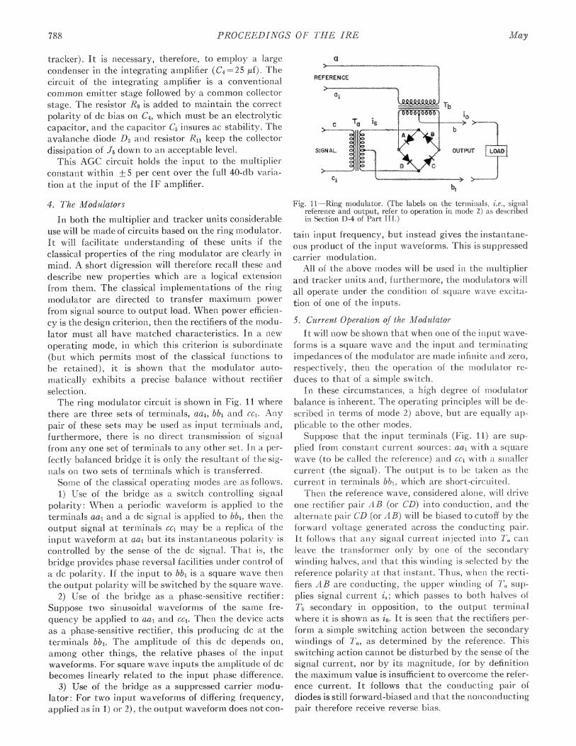
use will be nmade of circuits based on the ring modulator.It will facilitate understanding of these units if theclassical properties of the ring modulator are clearly inmind. A short digression will therefore recall these anddescribe new properties which are a logical ext-ensionfrom them. The classical implemnentations of the rinigmodulator are directed to transfer maximum powerfrom signal source to output load. When power efficiei-cy is the design criterion, then the rectifiers of the mnonu-lator must all have matched characteristics. In a newoperating mode, in which this criterion is subordinate(but which permiiits most of the classical functions tobe retained), it is show ii that the modulator auto-matically exhibits a precise balance without rectifierselection.The ring modulator circuit is shown in Fig. 11 where
there are three sets of termiiinals, aai, bb1 and Cci. Anlypair of these sets may be tused as input terminials anid,furthermore, these is no direct transmission of signalfromi any ofie set of terminals to any other set. In. a per-fectly balanced bridge it is only the resultanit of the signLals on two sets of terminals which is transferred.Some of the classical operatinig miodes are as follows.1) Use of the bridge as a switch controlling signal
polarity: Wheni a periodic waveform is applied to theterminals aa1 and a dc signal is applied to bbi, then theoutput signal at terminals cc, may be a replica of theinput waveform at aa1. but its instanitaneous polarity iscorntrolled by the sense of the dc signal. That is, thebridge provides phase reversal facilities under control ofa dc polarity. If the input to bb1 is a square wave thenLthe output polarity will be switched by the square wave.
2) Use of thie bridge as a phase-sensitive rectifieirSuppose two sinusoidal waveforms of the same ire-quency be applied to aal and Cci. Then the device actsas a phase-sensitive rectifier, this producinig dc at theterminals bb1. The amplitude of this dc depends oni,among other things, the relative phases of the inputwaveforms. For square wave inputs the amplitude of dcbecomes linearly related to the input phase difference.
3) Use of the bridge as a suppressed carrier modu-lator: For two input waveformis of differing frequency,applied-as in I) or 2), the output waveform does not con
OOOOTOO' ~~10c Ta isI11H b
SIGNAL OUTPUT [LOAD
Fig. II.-Ring modulator. (The labels oni the ternlinials, i.e., sigrialreference and output, refer to operation in mode 2) as describedin Section D-4 of Part [II.)
tamn input frequency, but instead gives the inistanitanie-ous product of the input waveforms. This is suppressedcarrier modulation.
All of the above m-lodes will be used in the multiplierand tracker umits and, furthermiore, the inodulatois willall operate under the conditioni of square wave exc ita-tioni of one of the inputs.5 Current Operation of the MWodulator
It will now be showni that wheni otne of the iiiput waveforms is a square wave and the inpllt anid terniinatingimpedanices of the modulator are made iiifimite anid zero,respectively, then the operationi of the modulator re-duces to that of a simple switch.
In these circumstances, a high degree of inodulatorbalance is inherent. The operatitig principles will be de-scribed in terms of mode 2) above, but are equally ap-plicable to the other modes.Suppose that the input terminals (Fig. I1) aie sup
plied from constant curreent sources: aa1 with a squaxrewave (to be called the referenice) and cc, with a smallercurreiit (the signal). The output is to be taketn as thecur-reiit in terminals Mtb, which are shoit-circuited.
Theii the referenice wave, considered alonie, will driveone rectifier pair AB (or CD) 'itto conduction, an-id thealternate pair CD (or AB) will be biased to cutoff by theforwai d voltage geiierated across the conducting pairIt follows that any signal current inljected into I, canileave the transformerm only by one of the secondarywindinig halves, aiid that this wilitig is selected by thereferenice polarity at that instant. Thus, when the rectifiers AB are coniducting the upper windiiig of 7'a sup-plies signal currenit is; which passes to both halves ofTb secon-dary in opposition, to the output termiinalwhere it is showrn as 1i. It is seeni that the rectifiers perform a simple switching actioni between the seconidarywindirigs of Ta, as determined by the referetice Thisswitching action cannot be disturbed by the senise of thesignal current, nor by its magnitude, for by definitiotthe maximuimi value is insufficient to overcome the relSer-ence currentt It follows that the coniducting pair ofdiodes is still forward-biased and that the noncotnductinigpair therefore receive reverse biis.
788 May

5Brown, et al.: A Lightweight and Self-Contained Airborne Navigational System
If the transformers are lossless and if the reverse con-duction of the cutoff diodes is zero, the whole signal cur-rent is transferred without loss to the output. Thus thediodes act as ideal switches simply routing the signalcurrent under control of the reference. The cutoff diodesdo in fact pass a small current under the influence of thesmall reverse voltage impressed on them by the voltagedrop of the conducting rectifiers. This constitutes anerror and is the main source of unbalance in the modu-lator. The percentage balance error may be made verysmall, for at maximum signal level its magnitude issimply the ratio of the leakage current to the referencecurrent. This will depend on the type of diodes whichwill be chosen according to the intended purposeof the modulator. When the waveformis are of rela-tively high frequency, germanium diodes are preferredbecause of their excellenit high-frequency characteristics.Then the ratio of currents may be in the order of a fewthousands. For low-frequency work, the silicon junctiondiode can raise this ratio above one hundred thousand.'4At the frequencies used in this paper, transformer bal-
ance is controlled simply by the turns ratio. Trans-former losses do not directly disturb the balance, butdo make the input and output impedances finite. In apractical system the input and output impedances mustnecessarily depart from the ideal, but it is not difficult tomake the source impedances several orders greater inmagnitude than the output impedance. This does notsignificantly degrade performance. Care must be takenthat the voltage developed across the load is not exces-sive, for if it is it can be shown that the bias across thenonconducting diodes will be overcome and a limitingaction will ensue.14 Correct design allows signal currentsto be modulated with a negligible transmission loss, andthe modulators described in the multiplier have bal-ances such that the output current at no signal is alwaysbut a few parts in a thousand of the output at full sig-nal. The accuracy of the whole system depends oni theinherent precision of these modulators.
6. The Multiplier"
The multiplication of the two Doppler spectra de-veloped by the channels A and C for Fig. 4 is performnedin a ring bridge modtulator. Some transformation of sig-nal form is required before this can be done, and hencethe description will be divided into two parts. First themultiplier modulator will be described, followed by adescription of the signal transforming circuits.
Suppose the phase-sensitive rectifier of Fig. 11 to besupplied with reference and signal current sources asshowxn. Each of these is to be in the form of a square
14 N. F. Moody, "A silicon diode modulator of 10-8 A. sensitivityfor use in junction transistor dc amplifiers," Etectronic Eng., vol. 28,pp. 94-100; March, 1956.
15 R. J. Bibby and P. M. Thompson, "A high-speed analog multi-plier with a linearity of better than - per cent," presented at theIRE-AIEE Transistor and Solid-State Circuits Conf., Philadelphia,Pa.; FebrLuary, 1958. See pp. 32-33 of Digest of Tech. Papers.
wave of frequency fo, and the amplitude of the signalsource is never to exceed that of the reference. The oper-ation depends on mode 2) of Section D-4, so that theoutput will be linearly related to any phase differencebetween the input waveforms and also to the amplitudeof the signal. When square waves are used in this way,it will be recalled that the diodes act as switches, and theoutput is very accurately related to the phase differenceand signal amplitude. The output current is given by
2io=is-( r/2),
7r
where iS is the amplitude of signal currenit at the sec-ondary of 'a, and 6 is the phase difference between sig-nal and refereince waveforms. For the present purposes itwill be convenient to miieasure phase angle such that zeroangle represents a quadrature relationship between in-put waveforms. Thus we introduce the new anglelewhere
6=0 - (12)7
It follows that
io i A (13)so that i0 is zero when either is or X is zero. The relationi-ship of (13) may be made the basis of a multiplier inwhich is and 4 are the analogs of the quantities whoseproduct is desired.The manner in which these analogs are developed will
now be described by means of Fig. 12, which shows thecomplete multiplying systenm. It is seen- to consist of thephase-sensitive rectifier, described above, whose inputsare developed from two further modulators, each ofwhich receives a reference square wave of the same fre-quencyfo. The output of one Doppler receiver, ii, is madeto phase modulate the square wave fo and so genieratesthe function 4 of (13). The other Doppler output, i2, iscaused to amplitude modulate its reference fo and so gen-erate a square wave i,, of (13). Thus the output of thephase sensitive rectifier represenits the product of thetwo Doppler inputs as required.These preliminary modulations of the two receiver
outputs are accomrlplished in the followting manner. Themodulation of i9 simply makes use of mode 3) of SectionD-4 and therefore needs no further description. Thephase modulation of il is a little more complex, as is seetnfrom Fig. 13. A first step is to perform suppressed carriermodulation on ii, as was done for i2, usinig the same ref-erence frequencyfo. This results in the waveform®. Thenthe reference square wave ® is integrated to generatewaveform(Q whose fundameintal is displaced ir/2 radiansto introduce the quadrature relationship required by(12). The suppressed carrier waveform © and the inte-grated reference (D are next added to produce the com-posite waveform i. The required waveform, in which ilis represented by 4), results simply by the generation of
1959 789

PROCEEDINGS OF TilA IRE
12
Fig. 12 -Blork diagram of the multiplier.
CPARRREEREDADDER iSQUARER
MODULATOR @
SQUARE WAVEGENERATOR AO
INTEGRATOR
SUPPRESSED _CARRIER
AMPLITUDE
MODULATOR
ADDER
I'
SQUARER
PHASE SHIFT PROPORTIONAL TOAMPLITUDE AND SENSE OF +-2
Fig. 13-Block diagramii anid waveforlns of the phase imiodulator,N.B. Althoigh the waveforms ilinstrate a case where the modtL-lating signal is a dc, the techniique is valid at freqtnencies tip tolhalf the (carrier freqLenicy. At these higher frequienicies ©will nolouiger he a true squiare wave.
a square wave®whose edges correspon-d to the timiies atwhich the composite waveform crosses the zero axis.The waveform ®is of conistant amplitude and becomesthe reference of the following phase-seiisitive rectifier,in which the multiplicationi is carried out. l'Jhe sup-
pressed carrier waveform resulting fronm i2 similarly be-comes the signal source to the multiplyinig modulator.
It may be shown that the over-all system miultipliesthe input funlctionis ii and i2 as follows. When i2 is zerothe phase sensitive rectifier of Fig. 12 has no signal in-putand, hence, delivers no output. Conversely, when it is
zero the referenice of the phase-sensitive rectifier is inquadrature with aiiy waveform at the signial terminials,and ag'ain there can- be no output. When- 4ij is presentthe reference is displaced +± fromn quadrature, so thatin the presence of signal there will be an output, de-pendent on the sign and amplitude of 1i. Similarly, theouitput depends also on the amplitude of i2 and includesthe sense of i2 since the signal waveform inverts wheni2 changes polarity.
The coniplete nuitiplier is thus seeni to conrsist of aphase-sensitive rectifier, two suppressed carrier miodu-lators, a sqtiare wave referen-ce generatoto in tegrtor,adder and squarer The pohase-sensitive rectifier anecl sup-pressed carrier modulators all follow the cuirent operated tech nique described in Section D)-4 anid soyield an accurate anid predictable performnaiace. Fhe re-m-iaining circuits are orthodox, and it is sn-iple to designlthem so that they produce little error.
T:he carriei frequency choseni for these operations is50 kc, because the input Doppler spectra exten-id to 20kc so the output spectrum contains frequencies up to 40kc. It is preferable that the carrier frequei)cy be imorethan twice this highest input frequency Because of thefrequenicy of operationi, switching speed becomies afactor in the choice of diodes for these circuits. For thediodes choseni, the unibalanice current was less thani I a,while the maximumji. value of sign-ial current chosen- was 2iaaeA comiplete circuit of the n-iultiplier system is showin ii
Fig. 14. The two suppressed carrier amplittude myioduItla-tors and the phase-sei-isitive rectifier are showin as A., B,and C, respectively. The square wave carriei for themodulators A and B and foi the itntegrator is providedby the multivibrator J:J2. This multivibrator is of a coni-vention-al cross-coupled desigin, whose resistance n-et-works R1C1 anid R6C3 are the prime frequenicy-controlliigelemenits. The output square wave is conLtrolled in aml-plitude by the eimitter network R2C2R4 by a process sim.-ilar to that used in the modulator of Section A. The output current is takeni by means of three current transformers connected in series T1l2T3. Tl and 1`2 becomepart of the two suppressed carrier miodulators, anLd 7Tdrives the initegrator.
Tlhe integiator conlsists of a current-limiting circuitand ani integrating amplifier. The purpose of the limitingcircuit R7R8D9ADoDj.Dr2 is to provide an accuratelyconitrolled square wave of cui-rent for the integratingamplifier. The integratirig amplifier consists of a com-noin emitter stage J., followed by a commiioiri collectoroutput stage J4 The constant of integration is con-trolledby the feedback capacitor Ci. It will be renremnbered thatthe integrator produces a trian-gular waveformii whichmust be added to the output of the suppressed carriermiodulator A. These waveforms are added as currents atthe emitter of J5, whose low impedance satisfies two re-quirenice]its. It provides a satisfactotly teri- iniiatioii forthe rin-g modulator It also allows accurate additionof the two waveforms, since its impedance is mniuch lowerthan either the reflected impedance of the ring modu.lator or, RU3 the predominant part of the output im-pedance of the integrator.The remainiiir-g transistors, J5J6J7.f8, comnprise the
squaring amplifier. J5 is a conimon base stage, followedby a common collector stage, J6, and an emittei coupledpair, J7Ja. R18 controls the amplitude of the output cur-rent of this last stage which drives T6, the refereice in-
put, to the phase senisitive rectifier C.
790 1A'lay

Brown, et al.: A Lightweight and Self-Contained Airborne Navigational System
Fig. 14-The multiplier circuit.
Note that the output sign-al of the suppressed carriermodulator B is applied via T5 as an input signal to thephase-sensitive rectifier C. Direct cascading of modu-lators in this way is often possible but requires some carein design. It is permissible for this reason. If the connec-tions from the secondary of T5 are lifted from C, ob-serve that the impedance seen at the transformer ter-minals is in the order of the source impedance of B. Sucha high impedance is appropriate for feeding modulatorC. Conversely, if the primary leads of T5 are lifted fromB, it will be found that the transformer inmpedanice is inthe same order as the output load on C. Such a lowimpedance provides a suitable termination for B.
This multiplier proves to have excellent stability andlinearity (+ 0.3 per cent) over a temperature range ex-tending froma-40o to +70°C. Accuracy relies only upona few passive conmponents and upon there being suffi-cienit gain for the feedback and squaring amplifiers towork correctly. The over-all Janus unit proves capableof supplyinig the correct output spectrum [C of Fig.15(a) ] at a level conistant within + 15 per cent over thewhole range of AGC control. Interference between thetwo channels is approximately -35 db.
E. THE FREQUENCY TRACKER
The multiplier delivers to the tracker a noisy spec-trum of the type shown in Fig. 3(b). This spectrum con-tains the sumn and difference frequencies of the Dopplersignals derived from the fore and aft antenna systems.Its idealized form is shown in Fig. 15(a) where the peak
(b)
I> e';XcI XA0-
N
23 4 5 6 7 8 9 10 IS 20
Ifd+ fd2FREQUENCY Kc Y
Fig. 15-(a) The form of the input spectrum for the tracker. (b)The spectrum resulting from modulating the above with fre-quency,f&.
due to the sum frequency (fd ±+f42) is shown at C, andthe difference frequency (fds -fd,) at D.The purpose of the tracker is to determine the sunm
frequency by examining the mean spectral energy ofthe peak C in a pair of similar frequency gates A and B.Should the gates deliver unequal energy, an error signial
1959 79X1
P:ROCEEDINGS OF TIIE IRE
()400 C/S DOPPLER FREQUENCY
MODULATOR OSCILLATOR SERVOL-.--
DOPPLER FREQUENCY OSCILLATOR BANDWIDTH CONTROL FROM REFERENCE
(FREQUENCY MODULATED) GROUND SPEED POTENTIOMETER
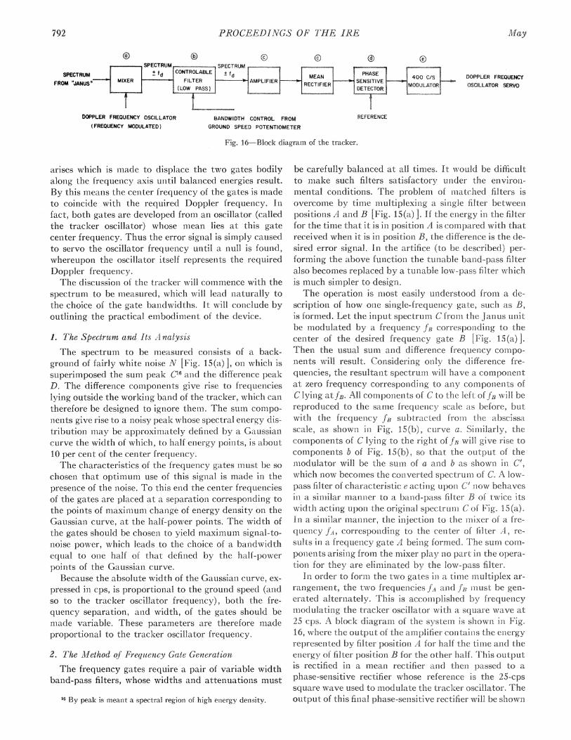
Fig. 16 Block diagramn of the tracker.
arises which is made to displace the two gates bodilyalong the frequency axis unltil balanced energies result.By this means the celnter frequency of the gates is madeto coincide with the required Doppler frequency. Infact, both gates are developed from an oscillator (calledthe tracker oscillator) whose mean lies at this gatecenter frequency. Thus the error signal is simply causedto servo the oscillator frequerncy until a null is found,whereupon the oscillator itself represents the r-equiredDoppler frequency
The discussion of the tracker will commenlce with thespectrum to be measured, which will lead n-aturally tothe choice of the gate bandwidths. It will coiiclude byoutlining the practical embodimient of the device.
1. The Spectrum and Its A nalysts
The spectrum to be measured consists of a back-ground of fairly white noise N [Fig. 15(a) 1, on which issuperimposed the sum peak C16 and the differenice peakD. The difference compon-ents give rise to frequencieslying outside the working band of the tracker, which cani
therefore be designed to ignore them. The sum comipo-nents give rise to a noisy peak whose spectral energy distributioni may be approxinmately defined by a Gaussiancurve the width of which, to half energy poinits, is about10 per cent of the cen-ter frequenicy.The characteristics of the frequency gates must be so
chosen that optimunm use of this signal is made im thepresence of the noise. To this end the center frequenciesof the gates are placed at a separatioii corresponding tothe points of maximum-l chan-ge of energy density oni theGaussian curve, at the half-power points. The width ofthe gates should be chosena to yield imiaximum siginial-to-noise power, which leads to the choice of a bandwidthequal to one half of that defined by the half-poweipoints of the Gaussiani curve.
Because the absolute width of the Gaussiani curve, ex
pressed in cps, is proportional to the groun-d speed (andso to the tracker oscillator frequency), both the fre-quency separation, and width, of the gates should bemade variable. These parameters aie therefore miadeproportionial to the tracker oscillator frequency.
2. The AMethod of Frequency Gate Genieration
The frequency gates require a pair of variable widthband-pass filters, whose widths and attenuation-s must
16 By peak is meant a spectral region of high en-ergy density.
be carefully balanced at all times. It xxTould be difficultto make such filters satisfactory unider the environ
mental conidition.s. The problem of miatched filters isovercome by time multiplexinig a single filter betwee.positioons A and B [Fi.g. 15(a) ]. If the eniergy im the filterfor the time that it is in position A is compared with thatreceived when it is in positionl B, the difference is the de
sired eiror signal. In, th1e artifice (to be described) pei
formin-Lg the above function the tuLnable band-pass filteralso becomes replaced by a tunable low-pass filter whichis much simpler to design.The operation is most easily understood from a de-
scription of how onxe single-frequency gate, such as B,is foinmed. Let the iniput spectrum C fromi the Janus unitbe modulated by a frequenicy fB correspondin.g to theceniter of the desired frequency gate B [Fig. 15(a) ].Then thle usual sum and difference fiequeiicy comnpo
nents will result. Considering oily the difference fre-quei]cies, the resultant spectrum-i will have a componetat zero frequiency corresponding to any components ofC lying atfJ. All components of C to the left of JB will be
reproduced to the same frequenicy scale Cas before, butwith the frequency fB subtracted froi the abscissascale, as shown iii Fig. 15(b), cmirve a. Siii-larily, thecomponlenits of C lying to the right of JB will give rise tocoilmpon]enits b of Fig. 15(b), so that the output of them:Xodulator will be the sumn. of a and b as showi n C',which now becom-es the coniverted spectruin of C. A low-
pass filter of characteristic e acting upon C' jiow behavesin a sinililar mianner to a band-pass filter B of twice itswidth acting upon the original spectrum-ii C of Fig. 15(a).In a, simiilar mainner, the in-jection to the miiixer of a frequenicy jA, corresponding to the ceiiter of filter A, re-
sults iii a frequency gate A being formed. he sumii com-ponieinits arising from the miixer play nio part ifn the opera-tion for they are e imyinated by the low-pass filter.
In order to formi-i the two gates ai a tin-te multiplex ar-
ran gem--en-it, the two frequencies fA andL fJR must be gen-
eiated alterriately. Ihis is accomiplished by frequenicymodulating the tracker oscillator with a square wave at25 cps. A block diagram of the systei m s shown in Fig.16, where the output of the amplifier containis the eiiergyrepresented- by filtem position A for half the timrle and theeinergy of filter position B foi the other half. This outputis rectified in a mean rectifier and then- passed to a
phase-senisitive rectifier whose reference is the 25-cpssquare wave used to imodulate the tracker oscillator. Tlheoutput of this finial phase-sensitive rectifier will be shown
SPECTRUMFROM 'JANUS"
792 May
(9)
Browvni, et at.: A Lightweight and Self-Contained Airborne Navigational System
FROM DOPPLERFREQUENCY OSCILLATOR
OUTPUT TO DOPPLERFREQUENCY OSCILLATORSERVO SYSTEM
Fig. 17-Complete circuit of the tracker. (The letters relate parts of the circuit to the blocks of Fig. 16.)
to be a dc signal whose sign and amplittude are a measureof the amount by which the center frequency fd of thetracker oscillator is misaligned with respect to the centerof the Doppler spectrum fd1 +fd. Thus, if the center fre-quencies are not coincident, the energies correspondingwith filters A and B will be unequal, and the mean recti-fier will conitain a c-omponent at the niodulating fre-quency. The phase-sensitive rectifier converts this com-ponent to a dc error signal used to control the mean fre-quency of the tracker oscillator anid so servo it until anull is reached.
In the particular model of the tracker to receive de-tailed description in this paper, the Doppler frequency isrequired in the form of a shaft position, and so the oscil-lator frequency is conltrolled by a motor driven resistivepotentiometer. Since a 400-cps motor is used for thispurpose, the dc error signal must be converted to a 400-cps error signal. A further modulator inakes this conver-sion in the right-hand box of Fig. 16.
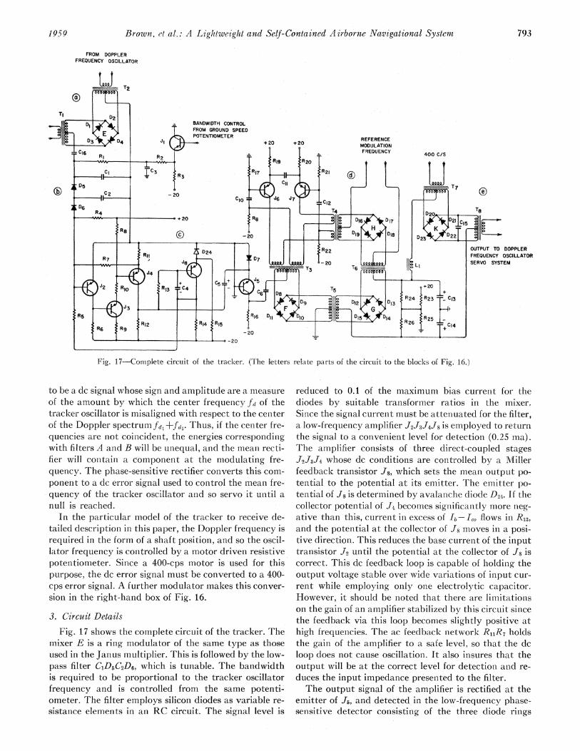
3. Circuit DetailsFig. 17 shows the complete circuit of the tracker. The
mixer E is a ring modulator of the same type as thoseused in the Janus multiplier. This is followed by the low-pass filter C1D5C2D6, which is tunable. The bandwidthis required to be proportional to the tracker oscillatorfrequency and is controlled from the same potenti-ometer. The filter employs silicon diodes as variable re-sistance elemeints in an RC circuit. The signal level is
reduced to 0.1 of the maximum bias currenit for thediodes by suitable transformer ratios in the mixer,Sin-ce the signal current must be attenuated for the filter,a low-frequency amplifier J2J3J4J8 is employed to returnthe signal to a convenient level for detection (0.25 ma).The amplifier consists of three direct-coupled stagesJ2J3J4 whose dc conditions are conitrolled by a MIillerfeedback transistor J8, which sets the mean output po-tential to the potential at its emitter. The emitter po-tential of J8 is determined by avalanche diode D24. If thecollector potential of J4 becomes significan-tly more neg-ative than this, current in excess of lb- 1 flows in RI,and the potential at the collector of J8 monves in a posi-tive direction. This reduces the base cuirrent of the inputtransistor J2 until the potential at the collector of J8 iscorrect. This dc feedback loop is capable of holdin-g theoutput voltage stable over wide variationis of input cur-rent while employing only one electrolytic capacitor.However, it should be noted that there are limitationson the gain of an amplifier stabilized by this circuit sincethe feedback via this loop becomes slightly positive athigh frequencies. The ac feedback network R11R7 holdsthe gain of the amplifier to a safe level, so that the dcloop does not cause oscillation. It also insures that theoutput will be at the correct level for detectioni and re-duces the input impedance presented to the filter.The output signal of the amplifier is rectified at the
emitter of J5, and detected in the low-frequency phase-sensitive detector consisting of the three diode rings
:1959 793

PROCEEDINGS OF THE IRE
F, G, anAd HI The purpose of this phase-sensitive de-tector is to detect comnponents in the collector signalof J, at the modulationi frequency (25 cps) of thetracker oscillator. Three ring nmodulators are used forthe low-frequency detectoi in order to circumvent thed-ieed for constructing curren-t traiasformers which operate satisfactorily at the low modulation frequency.In this arrangement neither the reference nor the signalfrequencies pass through trainsformers. Both the reference and the signial are modulated on] to a higher fre-quency carrier in. diode rings IH and F, respectively. Thereference and the signal pass through T6 and T5 as side-bands of the carrier frequency. The diode ring G thenperforms the demodulation, and the filter C13C4L re-moves all componeiits except the dc error signial. Thelatter is passed to the 400-cps modulator K, which con-verts the error signal to the appropriate form to actuatethe Doppler frequency oscillator servo.4 The 5-kc car-rier frequency is generated by a multivibrator J6J7,siImiilar in design to the multivibrator in the Janusmiultiplier. The description of tracker oscillator is deferred to Part IV, which deals with navigation. Theoscillator is a natural link between the radar and thenavigational devices, which themselves may assume avariety of forms. The oscillator may eveni become anintegral part of a navigational computer and so shouldbe described at the same time
F. DETERMINATION OF DRIFT ANGLE
It will be recalled from Part II that the antenna system produces two pairs of fore/aft beams [Fig. 2(b)]and that the axis of symmetry of the fore/aft beami sys-tem is aligned with the ground track in order to determine the track angle. The beam is switched by wave-guide switches at a frequenicy of about 1 cps. As a result,the 400-cps error signal from the tracker (Section E-3)also bears information concerning any misaligniment be-tween antenna axis and track as a component modu-lated by the 1-eps signal. This track error signal may beregained by applying the 400-cps tracker error signalto a phase-sensitive detecting system whose reference isthe square wave antenna switch control. The tech-niques follow those which have been described veryclosely, and details are therefore omitted.
G. POWER SUPPLIES AND REGULATORS"1
All the transistoi circuits are desigined to operate frompositive and negative 20-v rails. Potenitials, other hl ntiwhere + 20 volts oi giounid poteintial are required areobtained at the appropriate place in the cirenut by axeansof resistor netwrorks or avalanche diodes thus efiniinating the need for complex inter-unit wirii-ig. Although thecircuits are designed to be nioi-icritical of supply volta,git is conven-ient to use regulators as smoothing cruitsuTransistor regulators are lighter than choke-capacitorcombinatiorns; they protect the reimiainder of the circuitfrom the extreme surges present irn the aircraft supply;and may also be arranged to provide a low-inpedancesupply whicfi, in turn, reduces interaction between sep-arate circuits. The regulators are desigi-ied to in.iet allthese requirements aind, in addition., to be safe tinder alllikely conditions of surge anid oveirload, including a shortcircuit.The requirements of the klystroni power supply are
mmuch iwore stringent, 'both for stability and rippleFurtherniore, the problem is made extremiely difficultby the high voltages (500 to 1000) required by klystrons.T1he solution adopted is to con-ivert a highly stabilized 20volts to the required level with a dcto-dc coniverter consisting of a trainsformer coupled square waxve oscillatoi.Such aii oscillator cai be designed to have a very lowiniternal imi-ipedance, so that it is sufficienit to regulatethe low voltage input only. When operatinig it approxi-mately 8.5 ke, switching occurs in 2 Asec, so thatsmoothing of the output to the desired degree is a rela-tively simple matdter.
Fur-ther advantages of the square waxve oscillator am ethat 1) it can be protected against overload by design-ing for a cessation of oscillation on-i excessive circuit demand and 2) a sinigle oscillator can provide all the volt-ages required by the klysto-on. The suipply for the 600-mw klystroii provides 500 v + 2 v at 80 ma for the beam-supply with less than 2 my of iipple and eqiially stablesupplies for the ieflector and heater.
'a C A. Franklin, P. M. Thompson, an-d W. M. Caton '"Precisionhigh-voltage transistoi-operated power regulators, with overloadprotection, " submitted to IEE International Conyv on Tiansistor andAssociated Semiconlductor Devices, London, ELg., May 25-29, 1959e
Part IV-Data Conversion Between the Input Organs andPositional Computer
N. F. MOODY, P. M. THOMPSON, J. MITCHELL, AND J. H. GANTON
The preceding parts of this paper are concernedmainly with the input organs of an aircraft navigationalsystem, and in order that the significance of these vari-ous data sources could be appreciated, a broad outline ofthe navigational processes was given. The following
parts show the manner in which these data are used innavigation and give some treatment of the computersinvolved. The instruments to be described make directuse only of the following data sources: 1) a heading ref-erence, 2) a radar which gives ground speed (or incre
794 May

Brown, et al.: A Lightweight and Self-Contained Airborne Navigational System
mental ground distance), and drift angle, and 3) an air-speed indicator. Auxiliary checking means, e.g., mapfixes, will not be treated.The navigational computers involved are velocity
triangle, position, and steering computers. Electro-mechanical analog instruments have sufficient accuracyto satisfy the first and third functions, and their sim-plicity makes analog computation the preferred tech-nique. For positional computation this is not true, butanalog instruments are, nevertheless, often used. Thissituationi arises because these instruments exist as theresult of earlier systems and, indeed, are capable of giv-ing good service where the limiting accuracy of the radaris not desired.
In order to cater to the use of existing analog posi-tional computers, a special converter unit has been de-signed whose function is to make the radar outputcompatible with the positional computer. The con-verter, a description of wlhich follows, also provides asuitable output for the velocity computer. Part V de-scribes a digital form of positional computer wlhichdoes not require the converter unit and which itself pro-vides data in suitable form for an analog velocity com-puter. Whichever type of positional computer. is em-ployed, the analog velocity computer may be required,so for completeness a description of its operation is alsoincluded in this part. The functions of a positional com-puter are deferred to Part V, and no description of analoginstruments is given since these are well kn-own.'8 Thetreatment of steering computers, which are auxiliary toany system, is deferred to Part VI.
A. DIGITAL-To-ANALOG CONVERTER
The track distance output of the radar is essentiallyin a form suitable for a digital type of positional com-puter. However, in order to allow the use of the radarwith existing electromechanical analog computers, aconverter has been designed which converts the radaroutput into a form suitable for these systems.
Electromechanical analog positional computers re-quire a track angle input and either a distance or aground speed input. The radar supplies one of its out-puts in the correct mechanical form, i.e. drift angle,which is simply added to the heading angle to give trackanigle in the form required. This shaft angle is thentransmitted to the computer by a conventional synchrosysten. The radar Doppler output is fed to a converter,one of whose output shaft positions indicates groundspeed, while a second shaft position indicates the trackdistance flown.The functions of the converter are illustrated itn Fig.
18. As a matter of convenience the tracker oscillator ispart of this converter, for when positiotial computers ofthe type described in Part V are used, the oscillator sig-
18 S. I Frangoulis, "Design features of the ASN-7 navigationalcomputer," IRE TRANS. ON AERONAUTICAL AND NAVIGATIONALELECTRONICS, vol. ANE-3, pp. 108-112; September, 1956.
JOPPLER FREQUENCY GROUND SPEEDFROM OSCILLATOR DIGITAL TO ANALOG SHAFT POSITION
CONNECTION FROM CONVERTER DISTANCE FLOWNTRACKER SHAFT ROTATION
TO RADAR TO POSITIONAL COMPUTER AND
VELOCITY TRIANGLE COMPUTER.
Fig. 18-Functions of the digital-to-analog converter.
Fig. 19-Block diagram of the digital-to-analog converter.
nal is provided by one of its components. The converterdelivers the tracker oscillator frequenicy to the trackerand receives an error signal fromi the tracker which cor-rects this frequency to the center frequencv of the Dop-pler spectrum from the Janlus multiplier ini the radar.
Since either the speed or the distance output may berequired for a positional comnputer, both must be as ac-curate as the over-all systemi. No problem exists in theconversion of distance where the accuracy is, in fact,digital since each Doppler cycle can be counted and sotransmitted as an output shaft position. Speed (oscil-lator frequency) cannot be translated without instru-mental error, but the specified accuracy, ± 0.1 per cent,is adequate for most purposes.
Fig. 19 shows a block diagram of the converter whichis, in fact, digital-to-analog. This section1 describes firstthe operation of the tracker oscillator and its relatedcircuits, followed by a brief outlinie of the speed measur-ing and distance registering system.The tracker oscillator is connected with an electro-
mechanical tuning system and a 25-cps frequency mod-ulator. The tuning system consists of a transistor servo-amplifier'9 and a motor which drives a potentiometer,the setting of which determines the frequency. The os-cillator is tuned by a currenit whose value is proportionalto the potentiometer setting. Two types of oscillatorhave been used. Ini one circuit the currenit is used to con-trol the forward resistance of siliconi diodes used as vari-able resistance elements ill a \Vien bridge; while in theother the current is used to charge a capacitanice, dis-charged by a p-n-p-n trigger2' when the charge hasreached a predeter-mined value. Although the frequencyof both of these oscillators is proportional to the current,
19 P. M. Thompson and J. Mitchell, "Some solutions to problemsof operating germanium transistor servo amplifiers at high ambienttemperatures," IRE TRANS. ON CIRCUIT THEORY, VOl. CT-4, pp.190-193; September, 1957.
20 N. F. Moody and C. D. Florida. "Some new transistor bistableelements for heavy duty operation," IRE TRANS. ON CIRC[TITTHEORY, VOl. CT-4, pp. 241-261; September, 1957.
7951959
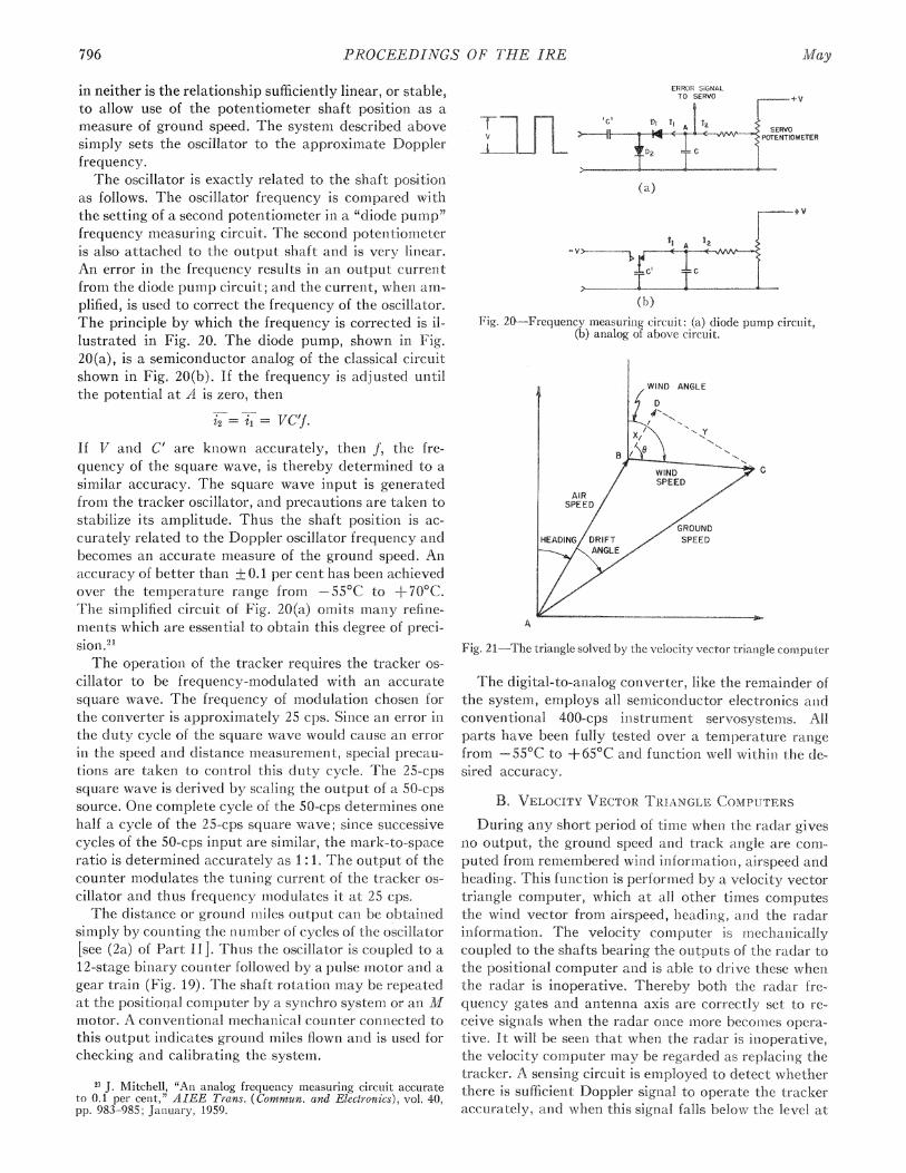
PROCEEDINGS OF ?THE IRE
in neither is the relationship sufficiently linear, or stable,to allow use of the potentiometer shaft position as ameasure of ground speed. The systemi described abovesimply sets the oscillator to the approximate Dopplerfrequency.The oscillator is exactly related. to the shaft positioen
as follows. The oscillator frequency is compared withthe setting of a second potentiometer in a "diode pump"frequency measuring circuit. The second potentiometeris also attached to the output shaft and is veiry liniear.Ani error in the fiequencv results in an output currentfrom the diode pump circuit; and the current, when1 am-plified, is used to correct the frequency of the oscillator.The principle by which the frequency is corrected is illustrated in Fig. 20. The diode pump, shown inJFig.20(a), is a semiconductor analog of the classical circuitshown in Fig. 20(b). If the frequency is adjusted untilthe potential at A is zero, then
i2 = il - VC'fIf V and C' are known accurately, then f, the fre-quency of the square wave, is thereby determined to asimilar accuracy. The square wave input is generatedfrom the tracker oscillator, an:d precautions are taken tostabilize its amplitude. Thus the shaft position1 is ac-curately related to the Doppler oscillator frequency aindbecomes anl accurate measure of the ground speed. Anaccuracy of better than + 0.1 per cent has been- achievedover the temperature range from -55°C to +70°C.The simplified circuit of Fig. 20(a) omLits many refine-nients which are essential to obtain this degree of preci-sion. 2'The operatioii of the tracker requires the tracker os-
cillator to be frequency-modulated with an accuratesquare wave. The frequency of modulation chosen forthe converter is approximately 25 cps. Since an error inthe duty cycle of the square wave would cause an errorin the speed an-d distance measuremeit, special precau-tions are taken to control this duty cycle. The 25-cpssquare wave is derived by scaling the output of a 50-cpssource. One complete cycle of the 50-cps deterniiies onehalf a cycle of the 25-cps square wave; since successivecycles of the 50-cps input are similar, the mark-to-spaceratio is determined accurately as 1:1. The output of thecounter modulates the tuning current of the tracker os-cillator and thus frequency rmodulates it at 25 cps,The distance or ground miiles output can be obtained
simply by counting the number of cycles of the oscillator[see (2a) of Part I]. Thtus the oscillator is coupled to a12-stage binary counter followed by a pulse motor and agear train (Fig. 19). The shaft rotation may be repeatedat the positional computer by a synchro system or an 11lmotor. A conveinitional mechanical counter coninected tothis output indicates grounid miles flown and is used forchecking and calibrating the system.
1i J. Mitchell, "An analog frequency measuring circuit accurateto 0.1 per cent," AIEE Trans. (Commun. and Electronics), vol. 40,pp. 983-985; January, 1959.
ERROR SIGNALTO SERVO +V
r t | 1 ~~~C. l 01 iA | 2SERVO
Y PO Al- * PTENTIOMETERi _ S 9~~~~~~2rt(a)
r+V
(b)Fig. 20 Frequency measurinig circuit: (a) diode punmp circuit,
(b) analog of above circuit.
A
Fig. 21-Trhe triangle solved by the velocity vector ti-iaagle com-nputer
The digital-to-aiialog converter, like the remainder ofthe system, employs all semiconductor- electronics anidconventional 400-cps instrunient servosystems. Allparts have been fully tested ovei a tlemplerature rangefrom -55°C to +650C an-d ftunctioin well withiii the de-sired accuracy.
B. VELOCITY VECTOR TR1:ANGLE COMPUT:ERSDuring any short period of time wheni the radar gives
no output, the ground speed and track angle are com-Li-puted fromii remiembered wind inforinmationi, airspeed anidheading. This function is performiieci by a velocity vectortriangle computer, which at all. other timnes computesthe wilnd vector from airspeed, heading, and the radarinformation. The velocity computer is m-techanicallycoupled to the shafts bearing the outputs of the radar tothe positional comrputer and is able to drive these wherithe radar is inoperative. Thereby both the radar frequenacy gates a id an-tenna axis are cornectly set to receive signals when the radar onice more becomes oper-ntive. It will be seeii that when the radar is inioperative,the velocity comnputer may be regarded as replacinig thetracker. A sensing circuit is employed to detect whetherthere is sufficient Doppler signsal to operatte the trackeraccurately, and when this signal. falls below the level at
796 May

Brown, et alc.: A Lightweight and Self-Contained Airborne Navigational System7
AUND SPEED ERROR AND COORDINATE OIFFERENT
FT ERROR FROM RADAR CONVERTER
AIRWIND SPEED AND SPEED HEADINGDIRECTION CORRECTION ANGLE
CROUND SPEED ANDVELOCITY TRIANGLE COMPUTER
DRIFT TO RADAR I eg AS IN FIG. 22b
Fig. 23-Arrangement of velocity vector triangle computer for conl-nection within the tracker feedback loop. (It should be noted thatthe conversion of error signlal which uses airspeed, as shownl, isimperfect, buit adequate for m-lost purposes. A better system,reqtmiring an extra servomotor when used with the type of posi-tional computer described in Part V, uses ground speed insteadof airspeed.)
WIND SPEED
(FIXED)
(b)Fig. 22-Block diagram of the velocity vector triangle computer
(a) while solving for winld, (b) while solving for ground speedand drift angle.
which the radar is more accurate than the velocity com-puter. At that time the computer takes over.
There are several suitable computers in existence, one
being used in the AN/APN-81 navigation system.7 Thiscomputer uses two synichro resolvers of the type dis-cussed in Section A of Part VI to solve the vector triangleshown in Fig. 21. Fig. 22(a) shows a block diagram ofthe computer arrangement used to calculate the wind.Potentiometers are set to provide voltages proportionalto the airspeed and ground speed. The ground speed isresolved by the drift angle into components perpendicu-lar to the airspeed y and parallel to the airspeed x-+A/S.When x and y are known, a single resolver solves the
right-angled triangle BDC for the wind speed and for 0.The wind direction is found by adding the heading to 0
with a differential gear, anid a potenitiometer is servoed
to represent wind speed as a shaft position.When there is no radar signal, relays are actuated to
lock the shafts representing wind speed and wind direc-tion and to change the configuration to that shown inFig. 22(b). The solution for ground speed and driftangle uses the same two resolvers and the same methodof calculation. The wind speed is resolved by 0 into com-ponents x and y, and a resolver is used to solve theright-angled triangle ADC for the ground speed and thedrift angle.A second type of velocity triangle computer is shown
in Fig. 23. This computer is connected within thetracker feedback loop, and the drift and ground speed
correction signals are resolved in such a way that theywill correct the wind direction and speed. The winiddirection and speed are used to recompute ground speedand drift which are fed back again to the radar. Theradar then holds the output of the velocity triangle com-puter to the radar accuracy, independent of the accu-
racy of the analog componenits in the triangle. When theradar signal fails, the -wind direction and speed remaini
at their last setting, and the computer continues to pro-
vide ground speed and drift anigle.
Part V-A Positional Computer of Digital AccuracyN. F. MOODY, P. M. THOMPSON, AND J. H. GANTON
The accuracv with which an aircraft can be flown to a
destinationi is determined by the accuracy with whichits position is known, since it is assumed that the exactposition of the destination is readily available. It is imn-portant, then, that a positional computer should becapable of using the full accuracy of the input organs. Asystem of input organs, already demonistrated capableof measuring distance to + 0.2 per cent and track angleto + 1° over laid22 has been described in Parts II-IV.
22 The error in track angle includes both drift angle errors due tothe radar anid headinig errors.
It is probable that this accuracy will be improved eveni
before this paper is published, and a distance accuracy
of 0.1 per cent may be possible. An exact knowledge ofdistance from base would be of great use to a navigatoreven if he did not know the exact direction in which hehad flown, since a radio bearing would allow himl to cor-
rect his position; or, failing that, the knowledge that hehas flown the exact distanice of his destination would en-
able him to fly on a line which will pass directly over it.The preceding part, in describing the functionis of the
digital-to-analog converter, introduced a concept of con-siderable importance. This concept is that the Doppler
(a)
1959 797
-e^.. r-F .|^_ .K..-GRO

PROCEEDINGS OF THkE fRE
radar output cani be con-siedeed as yielding incrementaldigital inforimatiotn conicerninig the distance flown., andit w as showii that the distance along the aircraft's trackcould be provided as a shaft position. without loss ofdigital accuracy. tJsually a positionial comiputer will resolve this iinciemnental distancc into coordinates suitablefor the frame of reference which it employs. This resolintion may be performed by the electromagnietic type ofresolver, described in Sectiotn A of Part VI, which wouldintroduce the uncertain errors common to anialog devices. These errors would be avoided if the resolutionwere performed digitally on the Doppler output signaldirectly.' In this case the distance error would be onlythat of the digital resolution, anid since the output of theradar may be regarded as digital, little further errorneed be introduced by the computer.
This part of the paper describes positionial computerswhich employ a digital technique havinlg much in comn-mon with analog techniques. The first section consists ofsome brief remarks on the miathenmatical operations tobe performed within the instrument This is followed bya discussion of the digital analog comnputing techniquesemployed, and a description of their incorporation insome practical positional computers.
A. THE MATHEMATICS OF POSITIONAL COMPUTATION(DIGITAL DISTANCE)
The purpose of the positional computer is to providecontinuously information about the aircraft's positionwith respect to a knowni reference grid. The two typesof reference grid considered are: 1) a square grid usedover small areas of the earth which may be consideredplane, and 2) latitude and longitude. This part of thepaper describes computer systems for use with eachtype of reference.The inputs to both positional computer systems coii-
sist of a traini of pulses representing the distance the aircraft travels and a synchro repeated shaft positioni repre-senting the track direction 0. For sufficiently small incre-menits of distance the track angle may be assumed con-stant, so that the computer will operate on i icrenmentalinformation in polar coordinate form. This motioni canbe resolved into rectangulai coordinates as follow s:
A(distance niorth) Ar cos 60,
A(distance east) Ar Sin 0.
Position on a square grid is given as distance niorth anddistance east of a datum, and therefore
distance north = Arj cos Oj + initial distance north,distance east - Arj sin 0j + initial distance east.
These equations completely describe the mathemiaticaloperations necessary for a square grid positional com-puter. Fig. 24 shows the logical block diagram of such acompu.ter.
Position on a latitude and longitude reference systemmay be computed by converting the increments of
WItTIAL NORTH SETTING
q
AR 5 UMM1NU REGISLRjCLONTAIUIINI
TRACK ANGLE / IS1ANC NONFROM A SYNCHRO
EOLVERX
DISTANG (aRmPULSES SUMMING REGISTER
CONTAINING'R SIN DISTANCE EAST
NITiA EAST SETTING
Fig. 24-Logical block diagram of the square grldpositional com.puter
INI1TIAL LATITUDE
SUMMING REGISTERAR SIN ES E CONTAINING
LONGITIJDE
AR N S SECILATITUDL)INITIAL LONGITUDE
Fig. 25-Logical block diagram of the latitude ayid longitudepositional computer.
travel north and east into increments of latitude andlongitude as follows:
latitude E Arj cos Oj + initial latitude,
and
longitude= ArF sin OA secant (latitude) j P initial longitude.
These equationis completely describe the mathematicaloperationis necessary for a latitude and lonigitude analogpositionial computer. Fig. 25 shows the logical blotck dia-gram of such a computer.
In both computers the mathematical operationis areperformied by means of the digital analog techniques tobe described in the next section. Suich techniques offerani. ideal solutioni since the radar systeim delivers the natural formll of iniput required and since the resulting com-puters prove to be siniiple, economical atld highly atcurate.
B. DIGITA1L ANALOG COMPUTATIONDigital anialog comnputation- is a formxi of an-alog com.-
putation where the values are transmiiitted as trains ofpulses. It follows that the logical block diagram of adigital anialog comiputer is identical to tlhat of any otherform-- of anialog comiputer, e.g., voltage oi miechanlical.However the data are always handled in the fornl- ofpulses, such that one pulse represents a sitngle iniclrem-nentof miagnitude. This single weight for a pulse distin-guishes the digital analog compputer from the conven-tional digital computer, with which, however, it slhares
78 Ad,"ay

Brown, et al.: A Lightweight and Self-Contained Airborne Navigational Systemn
fn, PULSES
fln2 PULE + BIDIRECTIONAL- COUNTER
nl3 PULSES '_
TOTAL n1+ nfl-n3 PULSES
Fig. 26-Digital analog addition and subtraction
IUNGsSUI~' 1.EnAIfA
FROMANGULAR SETTING
L SINE | LINPUTOUTPUT . PULSES
SPINNING ~GATE BIDIRECTIONALDRUM COUNTERSIGN AGO
OUTPUT SUJBTRACTLINE
Fig. 27-Logical block diagram of a spinninig drum device used asa sine function generator.
the property of delivering results where the accuracy islimited only by the resolution. As a member of the an-alog computer family it is most suited to a fixed pro-gram, and is often far simpler than a conventionaldigital computer.
This part of the paper illustrates how mathematicaloperations may be performed within a digital analogsystem, in preparation for a description of their practicalembodimenit in the positional computers. This paper isrestricted to the three operations necessary for the posi-tional computers: addition, subtraction, and resolutionby trigonometrical functions (to be described in thisorder).
1. Addition and SubtractionAddition and subtraction are usually performed
within a binary counter, as illustrated in Fig. 26. Thecounter must be bidirectional if both addition and sub-traction are required, and also there must be some provi-sioII to prevent coincidence between any two inputpulses. The usual practical arrangement is that there isa single input for digits and that the function of thecounter i.e., addition or subtraction, is determined atany time by another input, usually referred to as theadd-subtract line. A counter of this type is shown in theright-hand block of Fig. 27.
2. The Generation of Trigonometrical Functions
The digital analog resolving system to be described re-ceives two inputs: one in the form of a pulse train is thequantity to be resolved, and the other in the form of ashaft position sets in the angle 6. The resolver also de-livers its output as a pulse train, but this train must besummed in a counter to obtain the required function.The action of any trigonometrical resolver can be con-sidered as based on two properties. First the resolvermust be able to generate the function in the form of aratio between two numiibers of pulses, e.g., sin 6, and thenmust be able to control the magnitude of the vectors ac-cording to the input magnitude A, so as to generate therequired output, A sin 0. The following description willcommence by showing how the ratio sin 0 is generated.
Fig. 28-An early example of a spinning drum digitalresolver (resolutioni I).
Fig. 29-A photograph of an early spinning drum resolver. The deviceis taken apart in order to show the drum.
The resolver consists of a motor driven drum (Figs.28 and 29), on which are several tracks of perforations(or marks). In the center of the drum is a light sourceand on the outside, opposite the tracks, are photodiodesmounted in the outer casing. As the drum rotates themarks interrupt the light, thus causing the photodiodesto generate the pulses used in the system.Three of the five tracks are required to generate the
ratio sin 0: the function track, the reference track andthe sign track (to be introduced in this order). Thefunction track delivers output pulses whose sum will bethe required sine. Its perforations are so graduated thattheir density per unit angle C (measured around thedrum) varies according to the law k cos ¢.|, where k isan arbitrary constant. The zero position of 4 is definedby the reference track. It is necessary that the functionk cos k shall bear the sign for the value of 4 in each ofthe four quadrants. Since the function track cannot de-liver sign it is supplemented by the sign track, whichcontains a single mark extending from 90°-2 700.Throughout these quadrants the photodiode output ofthis track is treated as a negative quantity in accord-ance with the properties of a cosine.
1959 799

PROCEEDINGS OF Tl E IREr < ~~~~~~~~OUI'PUT_ERROR FROM TACHO SPINNING BIDIRECTIONALS GGNAL DRUM CCOUNTER
r OUTPUT
AMPLIFR TO SERVO MOTOR
Fig, 30 Logical block diagram of a spinninlg dirurn device used asa (ligital siue resoll7er.
Fig. 31-Logical block diagram of a spinninig drutlm device tised asa digital secant resolvers
It is now possible to show that the sum of the outputpulses (with sign determiined by the sign track) is pro-portional to the sine of the angle q through which thedrum is rotated. This operation is performed by connecting the output of the function track to the input ofa counter whose add-subtract line is actuated by theoutput of the sign track. This is illustrated in Fig 27where for the mioment the gate should be ignored. As thedrum is rotated from a position 0, the scaler total atany angle O' is
5,
Z k cos oj i-n k cos 4-d4 = k sin O'0
The sum may be made to approach the true integral asthe funiction track is more fiinely graduated, and thus ksin O' may be generated to the required digital accuracy.
In the practical system the drum rotates contiiiuously, but a similar effect cani be had by gating the out-put pulses to the counter so that they are accepted onlyover the interval 0 to O'. Thheni each rotatioii of the druimwill generate a score in the cotinter of k sin O'. Suchgating caln be performed by introducing a second photo-diode on the reference track, whose angular positioi caibe offset by 6' from the zero inidex position. If 0 is setequal to ¢b' and the gate is opened and closed by imnpulsesfrom these photodiodes, the scaler will score k sin. 0pulses per revolutioni. The block diagram of Fig. 27represents such a system. The angle 0 is set in by mieansof a second shaft (not showxn), which causes the ap-propriate photodiode to be displaced by turniing the ringgear on which it is mounited.The final step, controlling the magnitude A of the
output vector, k sin 0, is arranged as follows- Thedrum is caused to rotate once for every set n of inputpulses. Theri, since the counter receives a total of k sin 0
t I It I
PHOTO DIODE I PHOTO DIODE 2
OUTPUT OF PHOTO DIODE (a)I
DIFFERENTIATED (b)
POSITIVE ROTATION
DIFFERENTIATED (c)NEGATIVE ROTATION
OUTPUT OF PHOTO DIODE 2(di
1b1 GATED BY ld i.e
(') GATED BYd) (f) r- -t-
Fig. 32-Method by which the direction of rotation] of the drunm in
the secan-t resolver is detected.
pulses per revolution, the output/in-iput relationshipwill be
counter store k--- - sin, 0
no. of innut pulses aA sin. 0U
which approaches equality when the number of inputpulses s very large compared to a single set na IFhe re-quired control of drum rotation is provided by a fourthtrack linearly divided by a marks. If, as showxn in Fig.30, the input pulses are added in a bidirectional counterfromi- whose scoie the output of the linear track is subtracted, the instantaneous total i the scaler will repre-senit an error signal which uay be used to correct thxedrumn position. This error signial may therefore be miadeto actuate the drum m-iiotor to fornm a servosysteni-i whichnmay be damped by employing the usual tachomete gen-erator.
T?Lhe general navigation equations (Section A) wereseen, to require both cosine and secaiit function.s. It canbe shown that cosinie furctions are obtainable from another pair of photodiodes mounted on the function andsign- tracks, respectively, at right a igles to the existingpair. These new diodes feed a separate coui ter whichwvill generate A. cosine 0 when gated identically with thesin 0 counter. Secant can be resolved as follows. It willbe nioticed froml Fig. 30 that the resolver generatespulses at both linear and sine (or cosine) outputs. Sinicesecant is si-ilply the reciprocal of cosine it s necessaryonly to reverse the roles of the cmosi e atid linear outputs,as shown in Fig. 31, s0 that the cosine pulses are nowcompared with the incomin-ig traini and the linear pulsesare summed to produce the solution. The direction. ofrotation- of the drum deteimines the sign of the secantanid, in this block diagram, the output from the tachon:-eter generator indicates the direction Howevei, this
800 Ma4y

Brown, et al.: A Lightweight and Self-Contained Airborne Navigational System8
USUMMING REGISTER FOR DISTANCE EAST
BIDIRECTION ULS -JECHANICAL]COUNTER CHAIN MOTOR BOX COUNTER
ADD - SUBTRACTLINES
l FL OP
Fig. 33 Practical square grid positional computer.
method has limitations, for at very low speeds the de-sired output from the tachometer becomes masked byspurious signals. In the computer a second photodiodeis positioned on the linear track in such a way that itsoutput is 900 out of phase with the other photodiode onthe linear track, as in Fig. 32. The differentiated outputof the first photodiode is gated by the output of thesecond photodiode, so that positive pulses (e) representposi-tive rotation, while negative pulses (f) representnegative rotatio,n.The way in which the resolvers are used in the prac-
tical embodiment of the positional computer is discussedfurther in the next part of this paper.
C. PRACTICAL POSITIONAL COMPUTERS
This part shows the practical embodimient of thedigital analog componients in the square grid and thespherical grid positional computers shown logically inFigs. 24 anid 25.
Fig. 33 shows the practical block diagram of thesquare grid computer. A single spinning drum is used toresolve the distance input pulses by sin 0 anid cos 0, where0 is the track angle set from a synchro. The spinningdrum also generates two of the waveforms required bythe tracker. The output of the linear track is used di-rectly as the tracker oscillator which, it will be remem-bered from Section A of Part IV, required a superim-posed square wave FM. In fact the linear track bearsstep changes in the density of the marks so that the twogenerated frequencies lie above and below the meantrack frequency. The pattern of density changes is inaccordance with a second track (reference track fortracker, Fig. 28) which itself supplies the reference fre-quency required by the tracker for the demodulation.The output of the tracker becomes the input of theservoamplifier and regulates the speed of revolution ofthe drum.At this point it should be noted that a tachometer
generator mounted on the servomotor provides a 400-
cps voltage analog of the speed of the drumii and, hence,the ground speed of the aircraft. This voltage may beused directly by the velocity trianigle computers of Sec-tion B of Part IV in place of the ground speed inputshaft, since the purpose of the shaft is to set a potenti-ometer to such a voltage.The summing registers are composed of a bidirec-
tional counter chain, a pulse motor, and a mechanicalcounter. The add-subtract lines of the bidirection-alcouniter chain are controlled by the sign output of thespiinning drum. A traini of pulses from the spinniingdrum is summed in the scaler chain and the most sig-niificant figures of the numiber are converted into shaftrotation by the pulse motor. The pulse motor, in turni,drives the mechanical counter where distances arestored and displayed. A gear box betweeni the pulsemotor and the mechanical counter introduces a scalefactor, so that the counter reads directly in nauticalmiles. The mechanical counters are provided with fa-cilities by which the original position may be entered orcorrections may be miade during flight. The sine-cosineresolver and the two summing registers comprise a com-plete square grid computer.A comparison of the logical block diagranms (Figs. 24
and 25) shows that a latitude and longitude comnputer issimilar to the square grid computer with the addition ofa secant resolver. Similarly, the digital analog latitudeand longitude position computer of Fig. 34 is based onFig. 33, with the addition of a second spiinning drumused as a secant resolver. The sine output pulses of thesine-cosine resolver and the cosine output pulses of thesecant resolver are retimed to avoid coincidence anidthen conmpared in an error register (a bidirectional couni-ter chain). The error signal which is proportional to thenumber in the error register, i.e. the difference betweetnithe two trains of pulses, controls the speed of revolutioniof the secant drum. The add-subtract linies of the errorcounter chain are controlled by gates connected to thetwo inputs, by the sign of sine output from the sinie-
1959 801

2PROCEEDINGS OF THE IRE
TRACKANiGLE
COSINE OUTPUT PULSES
SECANT RESOLVER
SET FLIP RESETI IrLO
Fig. 34-Practical latitude and lonigitude positiomial compuiter
cosine resolver andL the sign of cosin:e output from thesecant resolver. The input pulses to the error registerare delayed to allow the add-substract lines time toswitch. The linear output of the secant drum and thecosine output of the sine-cosine drum are summed inregisters similar to those in the square grid computerwith suitable mechanical counters substituted. The lati-tude summinig register sets the angular input of the
secanit resolver by mneans of a suitable gear train Theaddition of these parts to the square grid computer con-verts it to a latitude anid lonigitude conmputer
These comibinations of semiiconductor electron'ics andmechanical components allow the constiructioni of bothlatitude and lotngitude, aiid square grid positional com-puters with digital accuracy but without the complication of a genieral purpose digital computei
Part VI--Steering Computers and the Choice of aComplete Navigational System
J. H. GANTON, P. M. THOMPSON, AND N. F. MOODY
The previous parts have been concerned with theequipnment necessary to define the position. of an air-craft. This part discusses the remnaining navigationalproblem, that of computinig a ioute to a destiniatioin.The route is usually preseinted to the pilot as a headingand a distance. The accuracy required need be nogreater than the precision with which ain aircraft can beflowin and it is postulated that the pilot cannot make useof solutions more accurate than one degree for headingand one per cent of the distance to be flown. The result-ant errors are not cumulative because the positionalcomputer provides a constant check on true aircraftposition. The accuracy of a conventional analog com-puter suffices, and the steering computers here describedare based on this method since it leads to the simplestinstrumentation.The equations to be solved depend on the type of
reference grid used. Steering computers are describedfor use with both the square grid type of positional con-puter and the latitude anid longitude positional comii-
puter. The output of the steering computer is trackangle and distance to the destinatioin; however, thepilot n-eeds headinig rather than track atigle so thatdrift angle is added before display. The squaie gridsteering computer solves a right-angle triangle, while forthe latitude and longitude steering computer mnore com-plex solutions are required Since latittude and longitudeare spherical coordiniates, an accurate distaiice and beai-ing require the solution of a spherical triaingle Wherethe position is calculated on a square grid, one axis ofwhich is referenced along the desired track, tFhe cornputer oLitputs are distances aloiig and across track. Irhenno separate computer is required; the steering inmforimation is provided by the positional computer directly.The purpose here is to compare the relative merits of
several methods of steering computation. Block dia-grams of a square grid steeriing computer, a latitude andloiigitude spherical steering computer, and two planeearth appioximations are developed from their equations. Sin1ce these computers are based. on syichbro re-
802 Maye

Brown, et at.: A Lightweight and Self-Contained Airborne Navigational System
solvers,u the characteristics of these components dictatethe form of the equations.
A. RESOLVER CHARACTERISTICSA synchro resolver is essentially a transformer whose
coefficient of coupling can be controlled by rotating ashaft. There are normally two stator windings at rightangles to each other and two rotor windings also atright angles. If one stator winding is energized by avoltage E, then the voltages on the rotor windings are:
Er = E sin 4
Er2 = E cos X),
y
DISTANCENORTH
3 DESTINATION
AIRCRAFT
DISTANCE EAST X
Fig. 35-Trianigle solution for square grid steering computation.
(14a)(14b)
where 4) is the shaft angle of the rotor. When both statorwindings are energized, one with voltage E1 and theother with voltage E2, then the voltages on the rotorwindings are given by
Er =E2 cos 4)- El sin 4)
Er2 = E1 cos 4 + E2 sin 4.(15a)(15b)
In the following discussion of the steering computers,the equations are manipulated in order to make use of(14) and (15).
B. SQUARE GRID STEERING COMPUTER
When the position of the aircraft and the destinationare known on a square grid, then the distance to desti-nation and the required track angle are computed bysolving a right-angled triangle (see Fig. 35). If the fol-lowing notation is used:
x =distance easty =distance northAx = (destination distance east) - (aircraft distance
east)Ay - (destination distance north) - (aircraft distance
north)R =distance to destinatione=-desired track angle,
thenAx
tan 6Ay
The relationshipsAx cos 0G-Ay sinmO= (16a)
and
R = Aycos+ Ax sinG (16b)
follow immediately, and notice that they are of the sameform as the set (15).
Fig. 36 shows the block diagram of a computer forsolving these equations. Voltages proportional to Ax andAy are set on potentiometers coupled to the inputs of a
23 E. B. Brown, 'Resolver analog computers," IRE Seconid NatI.
Conv. on Military Electronics, Washington, D. C.; June 17 18, 1958.See pp. 163-167 of the Conference Proceedings.
RESOLVER ISHAFT SERVOED TO B
Fig. 36-Logical block diagram of a square grid steering computer.
resolver. Since the voltage on one rotor winding is pro-portional to Ax cos X-Ay sin 4, the triangle is solvedwhen this output equals zero. Then the rotor shaft anigle4 equals the track angle 0 (or 0+r), and the magnitudeof the voltage on the other rotor winding is proportionalto the distance R of (16b).The practical computer employs a servomotor to posi-
tion the rotor, and with such a system there is no am-biguity in 4 since only one null is stable. The distancecan also be displayed as a mechanical position by meansof the servomotor and potentiometer shown in Fig. 36.The accuracy of this computer depends upon the size ofgrid covered and upon the accuracy of the resolver andpotentiometers.
C. LATITUDE AND LONGITUDE STEERING COMPUTERAn exact great circle course is obtained by solving the
spherical triangle joining the north pole, the aircraft andthe destination.23 For convenience, the equations aremanipulated using the standard spherical trigonometricnotation shown in Fig. 37. Symbols representing theknown and required quantities are then substituted.These symbols are shown and the two types of notationare related in Table I.
Conisider the spherical triangle ABC where A is thenorth pole, B is the aircraft, and C is the destination.The known quantities are A, b, and c; the desired quan-tities are B (the track angle) and a (the distance to des-tination). The spherical triangle equations used are thelaw of cosines,
cosa-cosbcosc +sinbsinccosA? (17)
and the identitycos c cosA =sin c cot b-sinA cot B. (18)
8031959
A y

8PROCEEDINGS OF THE IRE
(0) TO SOLVE FORG COS R
COS LOa COS LoC COS ALO SN R
VOLTAGE(SEE A BELOW) >
T MOTORSIN LCID
RESOLVER RESOLVER 2 RESOLVER 3 RESOLVER 4SHAFT SET TO ALOD SHAFT SET TOALO SHAFT SET TO LaA SHAFT SERVOEDTOG
A = SIN LaA GOS LOD COS A Lo COS LGa SIN LODib) TO SOLVE FOR R
COS R
SIN R
Fig. 38-Logical block diagram of latitude an-d longituide steeringcomputer: (a) solution for 6, and (b) solutioui for R
Fig. 37-Spherical trigonometry notation. In spherical triangle ABC,a, b, c represent the angular measure of sides BC, CA, AB, re-spectively. A, B, C represent the angles of the triangle.
TABLE I
LaA latitude of aircraftLOA longitude of aircraftLaD latitude of destiniationLOD longitude of destinationALa LaD -LaAALo LOA -LODR distance to destiniation0 track angle
LaALaDALo.R0
900 -c900 bAaB
If the identity (18) is niultiplied by sii b sin B and re-
arranged it becomes
cos B [sin b sin A ]+ sin B [cos c (sin b cos A)sin C (cos b)] 0, (19a)
wvhich m11ay be rewritten as
Cos 0 [cos LaD sin ALo] + sin 0 [sin LAa (cos LaD cos ALo)cos LaA (sin LaD)J 0. (19b)
This equation is in a formn wThich may be readily solvedfor 0 by means of four resolvers (Fig. 38). The shafts ofresolvers 1, 2, and 3 are respectively set to the latitudeof the destination, the difference in longitude betweenithe aircraft and the destination, and the latitude of theaircraft. The fourth resolver is used to solve for thetrack angle 0. Then the unused rotor winding on resolver3 gives
(cos b) cos c + (sin b cos A) sin c
cos a [by the law of cosines (17)]=cos R,
and the unused rotor winding oni resolver 4 givessinB [sin b sinA - cosB [sin b cos ccosA -cos b sin c]
sin a = sin R.
The distance R is calculated by use of a fifth resolver(Fig. 38).
Since the spherical computer is scaled for long dis-tances, it becomes inaccurate at short ranges, ai-id asupplementary computer is required. A short-rangeconiputer uses a plane earth approximation to the
spherical latitude and longitude reference grid. A number of approximations can be used, two of which will bediscussed. The range over which accurate results are re-quired determines the approximationi used a ld hencethe complexity of the computer.A computer based on a simple rectangular approxi
mation has sufficient range to supplement the sphericalcomputer. A suitable approximation- is based upon theassumption that the meridians of longitude are parallelwithin the area under consideration. In this approxi-mation
A(distance nortLh)) ALa
A(distance east) ALo cos LaD,
Fig. 39 shows a computer suitable for such a grid. It isa modified form of the square grid computer shown inFig. 36. The only addition is a resolver which calculatesdistance east firon ALo.
Increased ratnge results from representing latitude andlongitude by the trapezoid ABCD8 showni im Fig. 40The trapezoid is a better approxinmation- to latitude anldlongitude than-i the rectangle since it takes iiito actountthe coiivergence of the meridians betweenl the latitudeof the aircraft and the latitude of the destination.Triangle BDF is solved to finid the range R anid thetrack angle 0.
Since angle ABF is small, it may be assumcd that
FB AB ALo cos LaD (20)and
DE .ALa-Fd, (21)where
d ALo cos LaD cosC
and
ALoCOS +-- [cos LaD (COS ALa 1)
+ sin LaD (sin ALa)
The derivation of the expression for cos qY is straight-forward but tedious and is therefore omitted. If ALa issmall, the expression for cos f may be sijnplified, forthen it may be assumed that
804 My
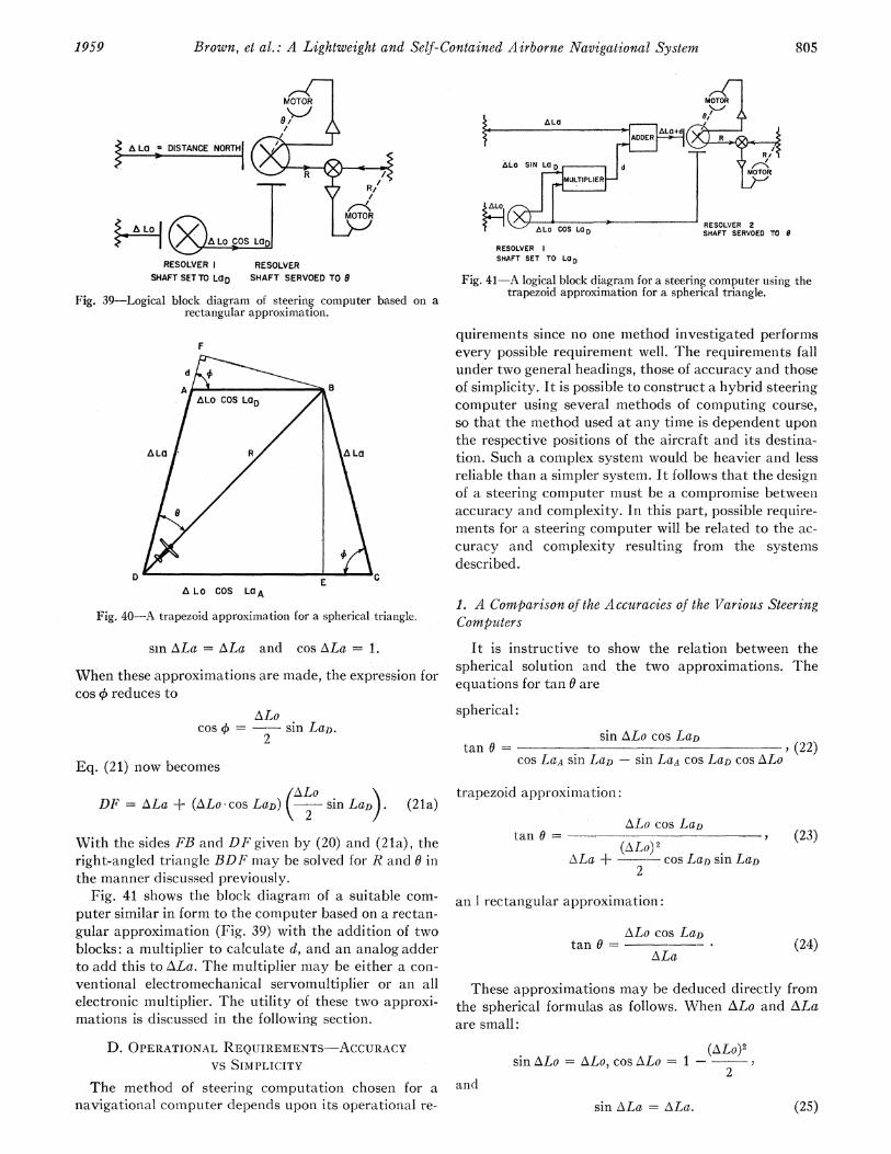
Brown, et al.: A Lightweight and Self-Contained Airborne Navigational System8
A LO = DISTANCE NORTH1
._
RESOLVER RESOLVERSHAFT SETTO LaD SHAFT SERVOED TOG
Fig. 39-Logical block diagram of steering computer based on arectangular approximation.
F
EA LO COS LaA
Fig. 40-A trapezoid approximation for a spherical triangle.
sin ALa = ALa and cos ALa = 1.
When these approximations are made, the expression forcos 4 reduces to
ALocos 4) = sin LaD.
2
Eq. (21) now becomes
/ALO \DF = ALa + (ALo cos LaD) 2 sin LaDs. (2 1a)
With the sides FB and DF giveni by (20) and (21a), theright-angled triangle BDF may be solved for R and 0 inthe manner discussed previously.
Fig. 41 shows the block diagram of a suitable com-puter similar in form to the computer based on a rectan-gular approximation (Fig. 39) with the addition of twoblocks: a multiplier to calculate d, and an analog adderto add this to ALa. The multiplier miay be either a con-ventional electromechanical servomnultiplier or an allelectronic multiplier. The utility of these two approxi-mations is discussed in the following section.
D. OPERATIONAL REQUIREMENTS-ACCURACYVS SIMPLICITY
The method of steering computation chosen for anavigational computer depends upon its operational re-
MOTOR TO
ALO O^ L C S I N g ? ~~~~~MOTORSHAFT SERVOED TO 0
RESOLVERSHAFT SET TO LaD
Fig. 41- A logical block diagram for a steering computer using thetrapezoid approximation for a spherical triangle.
quirements since no one method investigated performsevery possible requirement well. The requirements fallunder two general headings, those of accuracy and thoseof simplicity. It is possible to construct a hybrid steeringcomputer using several methods of computing course,so that the method used at any time is dependent uponthe respective positions of the aircraft and its destina-tion. Such a complex system would be heavier and lessreliable than a simpler system. It follows that the designof a steering computer must be a compromise betweenaccuracy and complexity. In this part, possible require-ments for a steering computer will be related to the ac-curacy anid conmplexity resulting from the systemsdescribed.
1. A Comparison of the Accuracies of the Various SteeringComputers
It is instructive to show the relation between thespherical solution and the two approximations. Theequations for tan 0 are
spherical:sin ALo cos LaD
tan 9 = , (22)cos LaA sin LaD- sin LaA Cos LaD cos ALo
trapezoid approximation:
ALo cos LaDtan 0= -
(ALO) 2ALa + --cos LaD sin LaD
2
(23)
an. I rectangular approximation:
ALo cos LaDtan 0 =
ALa (24)
These approximations may be deduced directly fromthe spherical formulas as follows. When ALo and ALaare small:
sin ALo = ALo, cos ALo= 1- (-ALo)22
andsin ALa = ALa. (25)
1959 805

PROCEEDINGS OF THE IREiME
TABLE I IEFFECT OF SYSTEM ACCURACIES ON TYPICAL COURSES
Great Circle Course
Track Angle
180
180
170
35'
05'
54'
630 42'
800
38"
04'
43'
Distanice
326
1327
2028
1340
215
952
Rectangular Approxinmation
TrackAngleError
34'
48'
59t
21'
10 53'
6° 03'
DistaniceErr-or
8 rn or 21 per ceiit
59 nun or 4' per cent
189 nmti or 9 per cent
40 nnm or 3 per cent
1 lIm
102 nm or 11 per cent
Trapezoid Approxi;maticoi
FrackAngleError
03'
I7'
20'
°O 03'
1.0'
371
DCistai-iceError
<1 urmi
5 tim oir0A per cent
19 nm or 1 per cent
6 nim or 5 pei cent
<1 niri
20 nm101- 2 Per cent
REMARKS
Accuracy of bothapproximations decreases with increasing range dueto assumption (25)
Trapezoid approxiimation becomes inaccurate whencoursecrosses equator dueto assumption- (27)
Rectanigular ap-proximation is in-accurate for mid-latitude courseswheie ALo > ALariue to assulrlptioii(28)
The spherical equationi (22) then becom-ies
tani 0=ALo cos LaD(zLo) 2
A.La + sin LaAcos LaD2
If it is assunmed that
sin LaA sin LaD, (27)
then (26) becomes the equation- of the trapezoid approxi-mation. This last assumption, (27), does not hold whenthe aircraft and the destinatioti are on opposite sides ofthe equator. However, near the equator sinl LaD is smalland the resultinig errors are small. If it is assumed that
(ALo)2--- sin LaA COS LaD = 0, (28)2
theii (26) becomes the equation of the rectangular ap-
proximation. Sinice sin LaA cos LaD has a ma-ximnumvalue of one half, (ALo)2/4 must be small with respectto ALa for the assumption (28) to be valid. This ap-
proximation is least accurate for midlatitude courses
which are approximately east-west, and thus the com-
puter based on this rectangular approximation has a
severe range limitation.The effects of these assumptions on some typical
courses are shown in Table II. This table compares some
t-ypical courses computed bv the two plane earth ap
proximations against, a true great circle bearing anddistance.
It will be noted that the simple rectangular approxi-mation is fairly accurate near the equator, but is notsuitable for flights over 200 miles at mediumn latitudes.However, at these latitudes the trapezoidal approxima-tion is adequate for flights of up to 1000 miles betweenturniiig poinits. Both these approximations have severe
limitations near the poles, where it is conminoii pi-acticeto use atnother system of coocrdinates.
While the great circle computer has 1io systemr errorsince it solves true spherical triangles, the requiirementsfor its components are the most stringent of any of thesystems discussed. This will become appaient when itis realized that one revolution of a resolver correspondsto a complete circumference of the eairth. Because theseerrors are due solely to the componienits, som-ie typicalresults of an experimental rmodel are tabulated in TableIII and give guidance on realizable accuracy.
The computer (Fig. 38) was constructed from fivesize-15 amiplifier cornipensated resolvers, for which suit-able transistor amplifiers have been (lesigledl. The tabledemoinstrates that such a computer gives a course within
2 or misses the destinatioon by approxmmlately 12miles, whichever is the greater. Thie comnputer is there-fore suitable for providing steering informnation at distances greater than 200 miles; but at distan-ices closerthan this a plane earth auxiliary com-lputer, such as theone usitng a rectangular approximationi (Fig. 39), isnecessary. The errors due to compoinents iii such shortrange computers are much less than for the sphericaltriangle computer and may be reduced to less than a
mile by suitable care in the electrical desigii.
E THIE CHOICE 0F A COMPLETE NAVIGATIONALCOMPUTING SYSTEM1
The final form of any coniplete navigational comput-ing system will be determined by the requirements of a
particular user, who will restrict the facilities to his par
ticular needs in the interests of equipment simplicity.It is quite possible, however, to make a flexible as-
seinbly of interchangeable computinig units so that aniy,or all, of the facilities of a general purpose system can- beselected at will. Such a system has great advantagesand may be developed with little further effort.
Several guiding priciciples, used to choose the facili-ties appropriate to a particular operatiotn nieed, will nowbe discussed. There seems little dLoubt that n-avigation
Triangle
LaA
75ON 8
50°N 7
40ON 7
440 30'N 4
60ON 7
La,0
SOON
)50N
5ON
700N
ALo
100
200
300
200
50
300
806 May
1.

Brown, et al.: A Lightweight and Self-Contained Airborne Navigational System
TABLE IIIERRORS IN EXPERIMENTAL SPHERICAL STEERING COMPUTER
Triangle Correct* Measured_ Track
LaA LaD ALo Angle Error
720S 69ON -660 3220 32' 31'84°N 69°N 1130 540 20' 02'30ON 45°N 150 330 57' 19'30ON 36°N 60 380 23' 15'30ON 320N 20 40 05' 1' 21'30ON 31ON 1° 400 29' 20 48'
* Assuming the earth is a perfect sphere.
Correct*Distance
7362 nm1444 nm1148 nm469 nm158 nm79 nm
MeasuredError
8 nm9 nm3 nm2 nm2 nm1 nm
lbased upon latitude and longitude is the best all-roundsystem. A position defined thus is unique and universal.Such a system could comprise a latitude-longitude posi-
tional computer and a great circle steering computersupplemented by a square grid steering computer. Thegreat circle computer would be used to guide the air-craft on the shortest path to its destination and thesquare grid computer to give a high accuracy of closingon the last 200 miles.A slightly simpler system results if the great circle
and square grid steering computers are replaced by thetrapezoidal type. Often the operational requirements,particularly for commercial flights, restrict air trafficto predetermined lanes and turniing points. Where suchroutes do not extend too close to the polar regions andwhen the turning points are separated by less than 1000miles, the trapezoidal steering computer is a suitablecompromise.
For flights within an area of a few hunidred milessquare, a simple square grid positional computer, to-gether with a square grid steering computer, will suffice;and if it is planned to fly a straight course from one
place to another, the steering computer may be elim-inated by referencing the square grid computer to thedesired track.The instrumentation of a basic system favored by the
authors makes use of three input organs, the radar air-speed indicator and north reference, coupled to a veloc-ity triangle computer and a square grid positional com-
puter. Then for many flights, the square grid computermay be referenced along and across track. If more com-
plex patterns must be flown, or if there is a need forgreater flexibility, the basic square grid computer may
be used as the first section of one of the more complexcomputer systems described above.
A CONCLUDING REVIEWThe foregoing paper has described in varying detail
the parts which. make up a complete navigational sys-
tem. The resulting instrument designs are flexible ofapplication, so that several complete systems may bebased on selections of them, or on arrangements consist-ing of some of these instruments used in conjunctionwith units developed elsewhere.Any of these navigational systems is a hybrid of three
techniques: Doppler radar, velocity computation basedon air data, and inertial navigation; and as is usual witha hybrid system, the relative importance of the various
parts within the system is determiined largely by thestate of development of each separate technique.
In the systems here described the dominarnt techniqueis the Doppler radar. The velocity computation is usedonly for the short periods of time when there is no radarsignal, anld the inertial device is merely a north refer-ence. If this paper had been written six years ago, thevelocity computer would have doniiinated; while in sixyears' time the inertial devices may becone far more im-portant and the radar may play the supporting role.Other input organs such as automatic radio star trackersmay become feasible due to increased mastery of UHFtechniques. As input devices of greater accuracy becomeavailable, the accuracy of the positiornal computer mayalso need improvement. This is expected to favor the de-velopment of the digital over the electrical or mechani-cal analog devices.
There has been, for some time, a need for a light-weight, self-contained navigational system, which is in-dependent of time, place, and weather conditions. Thispaper has presented some of the more recent work in thisfield; in particular, a system of navigation consistentwith present techniques and sufficiently flexible to per-mit the incorporation of future developments.
ACKNOWLEDGMENTThe navigation project has required the cooperation
of many workers and several organizations. The authorshave done their best to make the many acknowledg-ments required, and ask indulgence for any inadvertentomissions.The design authority also responsible for the early
system analysis, some of the electronic design, some ofthe early mechanical design, the supervision of flighttrials, and interpretation of results was the D.R.T.E.Electronics Lab., Defence Res. Board, Can. Thepersonnel included B. A. Walker, R. K. Brown incharge, and J. N. Barry, J. Bloom, D. R. Boulding,W. W. H. Clarke, G. T. Lake, J. A. Moffatt, and WV. W.Russell.The industrial con-tractor responlsible for the design
of antennas, microwave system, and RF amplifiers, andalso the construction of the user trials models was theCanadian Marconi Company of Montreal. The person-nel here included K. C. M. Glegg, H. Hansard, A Poz-nanski, and R. Reeves.The transistor radar and digital position computer
work was performed within the D.R.T.E. ElectronicsLab. The circuit and system design was by N. F.Moody, R. K. Brown, and P. M. Thompson, with con-tributions by J. Mitchell, C. A. Franklin, R. J. Bibby,R. Gagne, G. T. Lake, G. H. Booth, J. H. Ganton, R. S.Gruno, A. E. Gagnon, Y. Fujimoto, and G. St. Amand.The mechanical design and installation of radome and
antenna were performed by G. W. Morton, N. A. Harri-son, and E. P. Doherty of the D.R.T.E. Mechanical Sec-tion. All the flight testing used the aircraft and facilitiesof the Central Experimental and Proving Establish-ment, R.C.A.F., Ottawa.
1959 807