a hybrid active filter for a diode rectifier .... hybrid filter consist of an active filter which is...
TRANSCRIPT

International Research Journal of Engineering and Technology (IRJET) e-ISSN: 2395 -0056
Volume: 02 Issue: 04 | July-2015 www.irjet.net p-ISSN: 2395-0072
© 2015, IRJET ISO 9001:2008 Certified Journal Page 2057
A HYBRID ACTIVE FILTER FOR A DIODE RECTIFIER USED AS THE
FRONT END OF AN INDUCTION MOTOR DRIVE
Amritha Chandran1, Priya Jose2
1 Student, Electrical And Electronics Department, Adi Shankara Institute of Engineering And Technology, Kerala, India
2 Assistant Professor, Electrical And Electronics Department, Adi Shankara Institute of Engineering And Technology, Kerala, India
---------------------------------------------------------------------***---------------------------------------------------------------------Abstract – Power quality issues created in power
system are due to the nonlinear characteristics and fast
switching of power electronic equipment. The major
power quality issues such as harmonics, voltage
unbalance, and notching, poor power factor etc... are
studied. Among them harmonics is considered as one of
the major issue. The line side harmonic current in the
front end of a three phase diode rectifier of a 400 V, 15
KW induction motor drive is analyzed. To mitigate the
source side harmonic current, a transformer-less
hybrid active filter is realized. The hybrid active filter is
based on direct connection of a passive filter tuned to
seventh harmonic frequency in series with an active
filter using a three level Neutral point clamped PWM
converter. Simulations have been carried out on the
Matlab/Simulink platform and results are presented.
The experimental results verify the viability and
effectiveness of the proposed hybrid filter.
Key Words: Active filter, Passive filter, Neutral point
clamped PWM inverter, SRF Theory etc…
1. INTRODUCTION
Now a day’s power electronics based equipments are used
in industrial and domestic purposes. These equipments
have significant impact on the quality of supply voltage
and have increased harmonic current pollutions. The
drawbacks include additional losses in overhead and
underground cables, transformers and rotating electric
machines, error of measuring instruments, and low
efficiency of customer sensitive loads.
A medium-voltage motor drive for energy savings neither
require fast speed control nor regenerative braking when
it is applied to fans, blowers, pumps, and compressors.
Therefore manufacture uses a three-phase six-pulse diode
rectifier as the front end of the medium voltage motor
drive. The diode rectifier produces a large amount of
harmonic current at the line side. Pulse width modulated
(PWM) rectifier is capable of drawing three-phase
sinusoidal currents from the ac mains, so that it may be
preferable to the diode rectifier in specific low-voltage
applications. However, the diode rectifier is much more
efficient, reliable and less expensive than the PWM
rectifier in medium-voltage motor drives without
regenerative braking. Nevertheless, the diode rectifier
brings a large amount of harmonic current to the ac mains,
and therefore it does not comply with harmonic guidelines
or regulations.
Passive filters have been used earlier to mitigate problems
due to harmonics. But they have many drawbacks such as
resonance problem, dependency of their performance on
the system impedance, absorption of harmonic current of
non-linear load. To overcome these drawbacks active
filters are introduced. They inject harmonic voltage or
current with appropriate magnitude and phase angle into
the system and cancel harmonics of nonlinear load. But it
has also some drawbacks like high initial cost and high
power losses. This limits their wide application, especially
with high power rating system.
To minimize these limitations hybrid active filters has
been introduced and implemented in practical system
applications. Hybrid filter consist of an active filter which
is connected in series or parallel with a passive filer. It
provides cost effective harmonic compensation for high
power nonlinear load. Different control techniques are
present for extracting harmonic components of the source
current. Some of them are synchronous reference frame
(SRF) theory, instantaneous power theory (p-q), where
high pass filters extract harmonic components of the
source current from the fundamental components.[5][6]
International Research Journal of Engineering and Technology (IRJET) e-ISSN: 2395 -0056
Volume: 02 Issue: 04 | July-2015 www.irjet.net p-ISSN: 2395-0072
© 2015, IRJET ISO 9001:2008 Certified Journal Page 2058
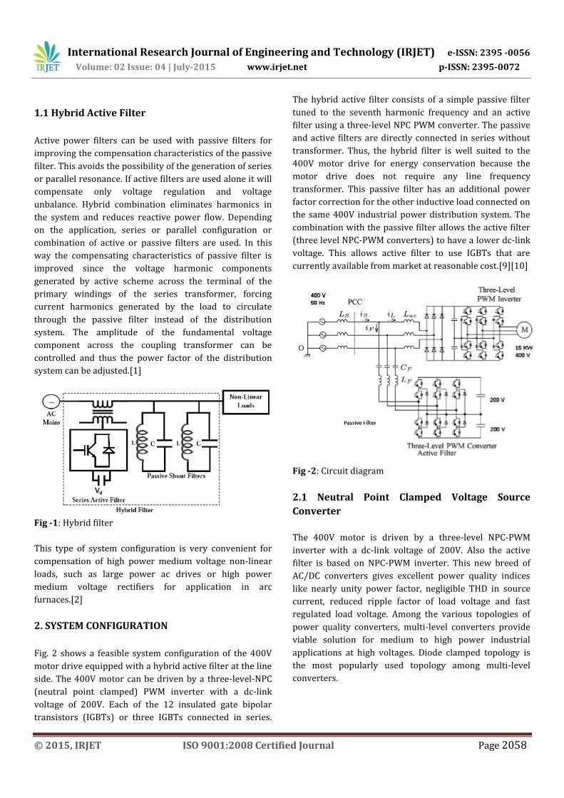
1.1 Hybrid Active Filter
Active power filters can be used with passive filters for
improving the compensation characteristics of the passive
filter. This avoids the possibility of the generation of series
or parallel resonance. If active filters are used alone it will
compensate only voltage regulation and voltage
unbalance. Hybrid combination eliminates harmonics in
the system and reduces reactive power flow. Depending
on the application, series or parallel configuration or
combination of active or passive filters are used. In this
way the compensating characteristics of passive filter is
improved since the voltage harmonic components
generated by active scheme across the terminal of the
primary windings of the series transformer, forcing
current harmonics generated by the load to circulate
through the passive filter instead of the distribution
system. The amplitude of the fundamental voltage
component across the coupling transformer can be
controlled and thus the power factor of the distribution
system can be adjusted.[1]
Fig -1: Hybrid filter
This type of system configuration is very convenient for
compensation of high power medium voltage non-linear
loads, such as large power ac drives or high power
medium voltage rectifiers for application in arc
furnaces.[2]
2. SYSTEM CONFIGURATION
Fig. 2 shows a feasible system configuration of the 400V
motor drive equipped with a hybrid active filter at the line
side. The 400V motor can be driven by a three-level-NPC
(neutral point clamped) PWM inverter with a dc-link
voltage of 200V. Each of the 12 insulated gate bipolar
transistors (IGBTs) or three IGBTs connected in series.
The hybrid active filter consists of a simple passive filter
tuned to the seventh harmonic frequency and an active
filter using a three-level NPC PWM converter. The passive
and active filters are directly connected in series without
transformer. Thus, the hybrid filter is well suited to the
400V motor drive for energy conservation because the
motor drive does not require any line frequency
transformer. This passive filter has an additional power
factor correction for the other inductive load connected on
the same 400V industrial power distribution system. The
combination with the passive filter allows the active filter
(three level NPC-PWM converters) to have a lower dc-link
voltage. This allows active filter to use IGBTs that are
currently available from market at reasonable cost.[9][10]
Fig -2: Circuit diagram
2.1 Neutral Point Clamped Voltage Source
Converter
The 400V motor is driven by a three-level NPC-PWM
inverter with a dc-link voltage of 200V. Also the active
filter is based on NPC-PWM inverter. This new breed of
AC/DC converters gives excellent power quality indices
like nearly unity power factor, negligible THD in source
current, reduced ripple factor of load voltage and fast
regulated load voltage. Among the various topologies of
power quality converters, multi-level converters provide
viable solution for medium to high power industrial
applications at high voltages. Diode clamped topology is
the most popularly used topology among multi-level
converters.
International Research Journal of Engineering and Technology (IRJET) e-ISSN: 2395 -0056
Volume: 02 Issue: 04 | July-2015 www.irjet.net p-ISSN: 2395-0072
© 2015, IRJET ISO 9001:2008 Certified Journal Page 2059
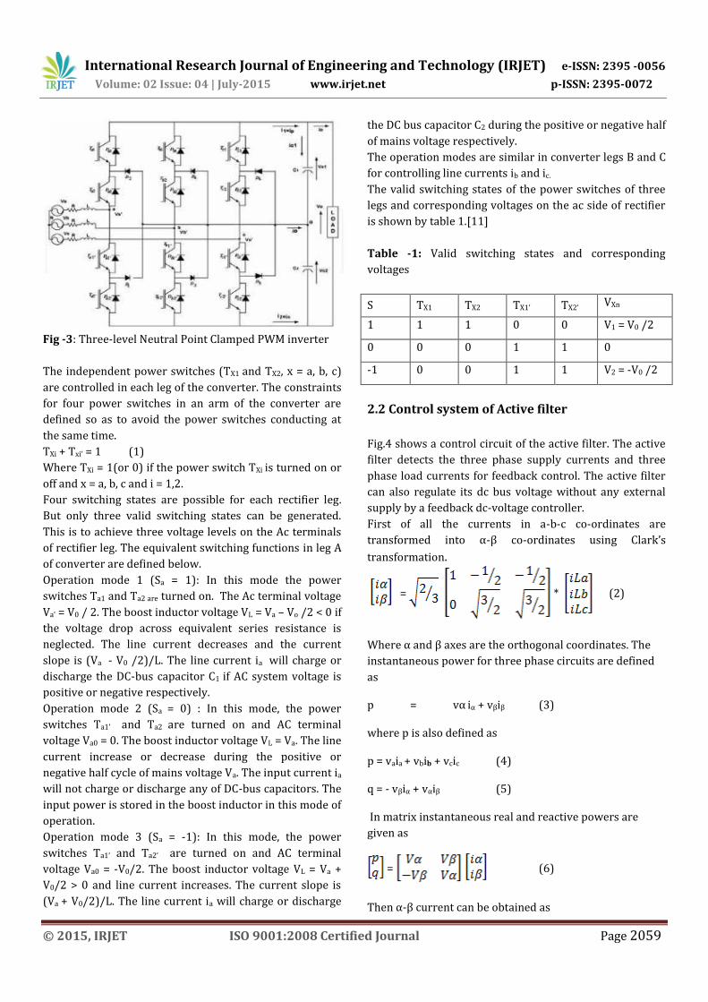
Fig -3: Three-level Neutral Point Clamped PWM inverter
The independent power switches (TX1 and TX2, x = a, b, c)
are controlled in each leg of the converter. The constraints
for four power switches in an arm of the converter are
defined so as to avoid the power switches conducting at
the same time.
TXi + Txi’ = 1 (1)
Where TXi = 1(or 0) if the power switch TXi is turned on or
off and x = a, b, c and i = 1,2.
Four switching states are possible for each rectifier leg.
But only three valid switching states can be generated.
This is to achieve three voltage levels on the Ac terminals
of rectifier leg. The equivalent switching functions in leg A
of converter are defined below.
Operation mode 1 (Sa = 1): In this mode the power
switches Ta1 and Ta2 are turned on. The Ac terminal voltage
Va’ = V0 / 2. The boost inductor voltage VL = Va – Vo /2 < 0 if
the voltage drop across equivalent series resistance is
neglected. The line current decreases and the current
slope is (Va - V0 /2)/L. The line current ia will charge or
discharge the DC-bus capacitor C1 if AC system voltage is
positive or negative respectively.
Operation mode 2 (Sa = 0) : In this mode, the power
switches Ta1’ and Ta2 are turned on and AC terminal
voltage Va0 = 0. The boost inductor voltage VL = Va. The line
current increase or decrease during the positive or
negative half cycle of mains voltage Va. The input current ia
will not charge or discharge any of DC-bus capacitors. The
input power is stored in the boost inductor in this mode of
operation.
Operation mode 3 (Sa = -1): In this mode, the power
switches Ta1’ and Ta2’ are turned on and AC terminal
voltage Va0 = -V0/2. The boost inductor voltage VL = Va +
V0/2 > 0 and line current increases. The current slope is
(Va + V0/2)/L. The line current ia will charge or discharge
the DC bus capacitor C2 during the positive or negative half
of mains voltage respectively.
The operation modes are similar in converter legs B and C
for controlling line currents ib and ic.
The valid switching states of the power switches of three
legs and corresponding voltages on the ac side of rectifier
is shown by table 1.[11]
Table -1: Valid switching states and corresponding
voltages
S TX1 TX2 TX1’ TX2’ VXn
1 1 1 0 0 V1 = V0 /2
0 0 0 1 1 0
-1 0 0 1 1 V2 = -V0 /2
2.2 Control system of Active filter
Fig.4 shows a control circuit of the active filter. The active
filter detects the three phase supply currents and three
phase load currents for feedback control. The active filter
can also regulate its dc bus voltage without any external
supply by a feedback dc-voltage controller.
First of all the currents in a-b-c co-ordinates are
transformed into α-β co-ordinates using Clark’s
transformation.
= * (2)
Where α and β axes are the orthogonal coordinates. The
instantaneous power for three phase circuits are defined
as
p = vα iα + vβiβ (3)
where p is also defined as
p = vaia + vbib + vcic (4)
q = - vβiα + vαiβ (5)
In matrix instantaneous real and reactive powers are
given as
= (6)
Then α-β current can be obtained as

International Research Journal of Engineering and Technology (IRJET) e-ISSN: 2395 -0056
Volume: 02 Issue: 04 | July-2015 www.irjet.net p-ISSN: 2395-0072
© 2015, IRJET ISO 9001:2008 Certified Journal Page 2060
= (7)
Fig -4: Control block diagram of Active Filter
Using ϴ as transformation angle, these currents are
transformed from α-β frame to d-q frame. This is defined
as Park’s transformation.
= (8)
DC components are extracted by using low-pass filters
(LPFs). The dc components are then transformed back to
a-b-c co-ordinate using reverse Park’s transformation and
reverse Clark’s transformation.[3][4]
2.3 Sinusoidal Pulse Width Modulation (SPWM)
The switches in the voltage source inverter can be turned
on and o as required. In the simplest approach, the top
switch is turned on If turned on and o only once in each
cycle, a square wave waveform results. However, if turned
on several times in a cycle an improved harmonic pro le
may be achieved.
Fig -5: Simple voltage source inverter
In the most straightforward implementation, generation of
the desired output voltage is achieved by comparing the
desired reference waveform (modulating signal) with a
high-frequency triangular carrier wave as depicted
schematically in Fig.5. Depending on whether the signal
voltage is larger or smaller than the carrier waveform,
either the positive or negative dc bus voltage is applied at
the output. Note that over the period of one triangle wave,
the average voltage applied to the load is proportional to
the amplitude of the signal (assumed constant) during this
period. The resulting chopped square waveform contains a
replica of the desired waveform in its low frequency
components, with the higher frequency components being
at frequencies of a close to the carrier frequency. Notice
that the root mean square value of the ac voltage
waveform is still equal to the dc bus voltage, and hence the
total harmonic distortion is not affected by the PWM
process. The harmonic components are merely shifted into
the higher frequency range and are automatically filtered
due to inductances in the ac system.
When the modulating signal is a sinusoid of amplitude Am,
and the amplitude of the triangular carrier is Ac, the ratio
m=Am/Ac is known as the modulation index. Note that
controlling the modulation index there for controls the
amplitude of the applied output voltage. With a sufficiently
high carrier frequency the high frequency components do
not propagate significantly in the ac network (or load) due
the presence of the inductive elements. However, a higher
carrier frequency does result in a larger number of
switching per cycle and hence in an increased power loss.
Typically switching frequencies in the 2-15 kHz range are
considered adequate for power systems applications. Also
in three-phase systems it is advisable to use FC/Fm = 3K
(K < N) so that all three waveforms are symmetric.
Fig -6: SPWM with fc/fm = 48, L/R = T/3

International Research Journal of Engineering and Technology (IRJET) e-ISSN: 2395 -0056
Volume: 02 Issue: 04 | July-2015 www.irjet.net p-ISSN: 2395-0072
© 2015, IRJET ISO 9001:2008 Certified Journal Page 2061
2.4 Design of passive filter
The passive filter used here has the function of mainly
absorbing harmonic current produced by the diode
rectifier. Therefore the passive filter should have
impedance as low as possible at the fifth, seventh, 11th, and
13th harmonic frequencies to achieve good filtering
characteristics. For this reason most hybrid filters consist
of fifth and seventh tuned LC passive filter and a high pass
filter. However, many passive elements are required thus
making conventional hybrid filter costly and bulky.
Moreover, the high pass filter allows a no negligible
amount of switching ripple current to flow from active
filter into supply, so it is mandatory to install an additional
switching-ripple filter. The 11th and 13th harmonic tuned
LC filters can be used instead of high pass filter. This
passive filter configuration would still be bulky, although
no switching-ripple filter may be required.
The hybrid filter proposed in this paper uses a single LC
filter per phase as passive filter. It is characterized by
being tuned to seventh harmonic frequency which is the
second most dominant. The reasons for selecting seventh
harmonic frequency are summarized below. The LC filter
tuned at seventh harmonic frequency is less bulky and less
expensive than that tuned at fifth harmonic frequency. The
seventh harmonic tuned filters presents lower impedances
at the 11th and 13th harmonic frequencies than the fifth
harmonic frequency tuned filter does. The filtering
characteristic for the fifth harmonic frequency can be
significantly improved by the control strategy used in this
paper.
Design of inductance and capacitance has many criteria
that should be considered. The impedance of LC filter
must be as low as possible, thus contributing to good
filtering characteristics and making active filter voltage
rating low. The required dc voltage of the active filter
should be around 200V for this system, so that general
purpose IGBTs can be used for active filters. These imply
that the capacitance values should be as large as possible,
whereas the inductance value should be as low as possible.
However, a large capacitance value is accompanied by a
large amount of capacitive reactive current owing into the
LC filter. Moreover a low inductance value would make the
LC filter have no capability of suppressing the switching
ripples caused by the active filter.[7]
3. SIMULATION RESULTS
The simulation is carried out using MATLAB/SIMULINK
software. Fig.5 shows the basic simulation model of hybrid
filter that correlates to the system configuration shown in
Fig.2 in terms of source, load, hybrid filter and control
blocks. T he considered load is an induction motor drive
with rating 400V, 15 KW. The hybrid active filter consist of
a passive filter tuned to seventh harmonic frequency and
an active filter using a three-level NPC PWM inverter. The
passive and active filters are directly connected without
transformer. The performance of active filter is based on
SRF theory and sine PWM method.
Fig -7: MATLAB/SIMULINK model
The generation of voltage templates (sine and cosine)
plays an important role in the calculation of reference
source currents. These templates are generated using PLL,
and therefore the tuning of PLL is crucial. The operation of
PLL is slow, and is also imposes some amount of delay in
computation. THD is observed with and without
connecting hybrid active filter.

International Research Journal of Engineering and Technology (IRJET) e-ISSN: 2395 -0056
Volume: 02 Issue: 04 | July-2015 www.irjet.net p-ISSN: 2395-0072
© 2015, IRJET ISO 9001:2008 Certified Journal Page 2062
3.1 Uncompensated System- source voltage and
current waveform
Fig -8: Source Voltage
Fig -9: Source Current
3.2 Uncompensated System- Load voltage and
current waveform
Fig -10: Load Voltage
Fig -11: Load Current
The voltage and current waveform of uncompensated
model is shown above. It is clear from the figure that the
current and voltage waveform is distorted.
3.3 Compensated System- Source voltage and
current waveform
Fig -12: Source Voltage
Fig -13: Source Current
3.4 Compensated System- Load voltage and
current waveform
Fig -14: Load Voltage

International Research Journal of Engineering and Technology (IRJET) e-ISSN: 2395 -0056
Volume: 02 Issue: 04 | July-2015 www.irjet.net p-ISSN: 2395-0072
© 2015, IRJET ISO 9001:2008 Certified Journal Page 2063
Fig -15: Load Current
Table -2: Measured Harmonic Spectra And THD values of
source current
1 3 5 7 11 13 THD
Uncompensa
ted System
100 3.3 7.5 3.5 1.2 1.6 23.9
Compensated
System
100 0.4 2.6 0.4 1.4 0.9 4.86
4. CONCLUSIONS
A hybrid active filter for harmonic current mitigation of a
diode rectifier has been studied. The hybrid filter is
characterized by series connection of a simple LC filter
tuned to the seventh harmonic frequency and a small-
rated active filter. The Active filter used is based on three-
level-Neutral point clamped PWM inverter. The hybrid
active filter has the following advantages over a pure
active filter and a traditional passive filter consisting of
multiple-tuned LC filters and a high pass filter: The active
filter taking part in the hybrid filter is much smaller in
converter capacity than the pure active filter, The simple
single-tuned LC filter used in the hybrid filter is much
smaller in size, lower in cost and weight, than the
traditional passive filter.
The control strategy for reference current generation for
active filter is based on SRF theory. Sinusoidal pulse width
modulation has been used for gating signal generation.
Both experimental and theoretical analysis has verified
that hybrid filter has provided satisfactory harmonic
filtering of the diode rectifier. The THD obtained here are
within the limit of 5 percentages prescribed by IEEE.
ACKNOWLEDGEMENT
I would like to express my sincere gratitude to our
institution, Adi Shankara Institute Of Engineering and
Technology, Kalady. I also thank our honorable Principal
Dr.N. Hariharan for providing us with all the facilities for
making my project a success.
I am grateful to the Head of the Department
Mrs.Krishnakumari.T for her constant encouragement and
support.
I would like to extend my gratitude to my guide Mrs.Priya
Jose, Assistant Professor of EEE department for her
inspiring assistance, support and timely advice and for her
enterprising attitude that made my project successful.
Also I would like to thank our PGPP Divakara Menon Sir of
the department for giving us innovative suggestions and
assisting us in times of needs. This acknowledgement will
stand incomplete if my parents, friends and classmates are
not thanked whose constant encouragement and timely
criticism helped us to a great extent. They were
instrumental in keeping my spirit high and their
association with me will be always remembered.
REFERENCES
[1] H. Akagi, New Trends in Active Filters for Power
Conditioning, IEEE Trans. Ind. Appl., Vol. 32, No. 6,
November/December 1996.
[2] Bheem Singh, Kamal Al-Haddad, and Ambrish
Chandra, A review of active filters for Power Quality
Improvement, IEEE transactions on industrial
electronics, vol. 46, no. 5, October 1999.
[3] E.H.Watanabe, New Concepts of instantaneous active
and reactive power in electrical systems with generic
loads, IEEE Trans. On. Power Delivery, Apr. 1983.
[4] Bhim singh, A comparison of control Algorithms for
DSTATCOM, IEEE Trans. On. Power Delivery, June.
2009.
[5] Hirofumi Akagi, New trends in active filters for power
conditioning, IEEE trans-actions on industry
applications, vol 32, no 6, November December 1996.
[6] A. Bhattacharya, C. Chakraborty, and S. Bhattacharya,
Shunt compensation: Re-viewing traditional methods
of reference current generation, IEEE transaction on
industrial electronics, Sep. 2009.
[7] Hideaki fujita and Hirofumi Akagi , A practical
approach to harmonic compensation in power
systems-Series connection of Passive and Active filters,
IEEE Transactions on industry applications , vol
27,No. 6,November/December 1991.
[8] Reyes S. Herrera and Patricio Salmern , Instantaneous
Reactive Power Theory: A Comparative Evaluation of

International Research Journal of Engineering and Technology (IRJET) e-ISSN: 2395 -0056
Volume: 02 Issue: 04 | July-2015 www.irjet.net p-ISSN: 2395-0072
© 2015, IRJET ISO 9001:2008 Certified Journal Page 2064
Different Formulations , IEEE transactions on power
delivery, vol. 22, no. 1, January 2007 .
[9] H. Akagi, A hybrid active filter for a three phase 12
pulse diode rectifier used as the front end of a medium
voltage motor drive, IEEE transactions on power
Electronics, VOL. 27, NO. 1, January 2012.
[10] Makoto Hagiwara, and Hirofumi Akagi, Fellow, IEEE,
"A Medium-Voltage Motor Drive With a Modular
Multilevel PWM Inverter", IEEE Transactions on
Power electronics Vol. 25, No. 7, July 2010.
[11] Abdul Hamid Bhat and Pramod Agarwal, "Improved
Power Quality AC/DC Converters".
BIOGRAPHIES
Amritha Chandran was born on
12th April 1991. She received her
Bachelor Of Technology Degree
In Electrical And Electronics from
Met’s School Of Engineering, Mala
under Calicut University in 2013.
She is currently pursuing Master
Of Technology In Power
Electronics And Power System at
Adi Shankara Institute Of
Engineering And Technology
Kalady, Ernakulam. Her current
research interests include
Harmonic Mitigation in non-
linear loads.
Priya Jose was born on 13th July
1984. She received B-Tech
Degree In Electrical and
Electronics from MA College,
Kothamangalam. She received M-
Tech Degree In Industrial Drives
and Control from Rajagiri College,
Kakkanadu in 2012. She is
currently working as Asst
professor in Adi Shankara
Institute Of Engineering And
Technology Kalady, Ernakulam.
Her current research interests
include power quality issues,
virtual capacitance inverter.
Author’s Pho to
Author’s Ph oto