a history and classification of tensile restrained arches · a history and classification of...
TRANSCRIPT
A History and Classification of Tensile Restrained Arches.
Lightweight Structures Unit / University of Dundee 1/16
A History and Classification of Tensile Restrained Arches
Burford N.K., Gengnagel, C. & Smith F., W.
Abstract
Arches have been an enduring structural form of traditional, Gothic and Renaissance architecture since the Romans brought them to prominence some 2000 years ago. While there were extensive developments in arch shape, structural understanding and applications during this period it wasn’t until the Industrial Revolution and the advent of new, high strength, lightweight materials that a step-change was made to the form, span and construction of arches with the introduction of the first lightweight, filigree arch structure at Coalbrookdale in 1779. The advent of the tensile restrained arch occurred shortly thereafter due to the need to provide significantly larger span structures, more efficiently and economically. Over the next 100 years, spurred by the railway construction boom, there followed unprecedented innovation in materials and construction techniques. Better understanding of structural behaviour resulted in the development of numerous new structural forms of restrained arch. In recent times, particularly over the last 20 years, there has been a gradual re-emergence of the tensile restrained arch in a number of significant architectural projects. The use of non-linear computer analysis tools has lead to a new generation of tensile restrained arch. These latest lightweight, hybrid structures explore new architectural aesthetic and tectonic ideas as well as potentially providing higher levels of structural and material efficiency for widespan applications. The following paper discusses the influence and potential of lightweight, efficient arches using comparatively thin, curved compression members restrained predominantly by systems of tensile elements. A new typology and classification system is proposed which defines the principal underlying criteria for their design, classifies currently known examples and proposes alternative configurations and forms. A numerical study compares aspects of the structural behaviour of the alternative systems when subjected to different loads. The efficiency of the principal systems is discussed in relation to ergonomics, aesthetics, buildability and structural behaviour. Recent advances in materials and tensile restrained arch design are discussed in relation to the potentials of these systems in future construction applications. (332)
The Genesis of Lightweight Restrained Arches
The arch is one of the oldest structural elements of traditional architecture and appears in two typical forms: the
rigid masonry arch constructed from natural stones or bricks or the flexible arch constructed from wood,
bamboo and reed bunches. The first lightweight arches were designed by Philibert de l´Orme (1510-1570),
using short, thick timber boards arranged in a single system of coupled circular and pointed arches. The first
arch bridge, constructed from high strength cast iron was built in 1779 in Coalbrookdale, illustrating the
opportunities afforded by the introduction of cast iron, to build structures composed of discrete, thin, straight
and curved, compression elements. It was with the development of wrought iron with its higher tensile strength
that made it possible for designers to develop the first truly lightweight filigree restrained structures, like the
roof structure of the Theatre Francais in Paris, (1786). With better understanding of stability problems and the
need for bigger spans to cover larger railway termini, arch structures became increasingly lightweight and
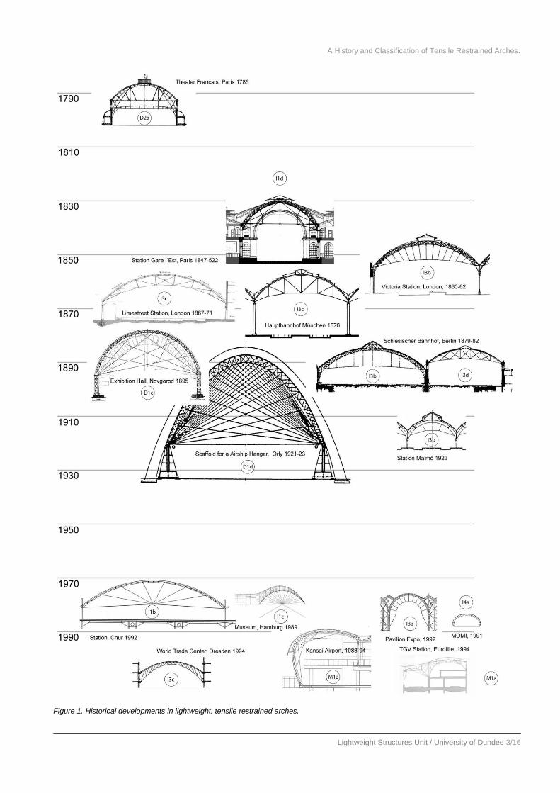
transparent. Between 1889 – 1923 many variations of the principles were developed to provide efficient, wide-
span enclosures principally for train sheds during the railway construction boom, facilitated by the high-strength
materials with the ability to easily produce connections between the lightweight, filigree members (Figure 1).
However, by the 1930s, with the development of high strength rolled steel and better methods of analysis for 2-
pin, 3-pin and rigid trussed arched solutions, further innovation and application of restrained arch solutions
ceased. It wasn’t until the late 1980s through the use of more sophisticated computer analysis tools that a second
generation of rail interchanges needed more sophisticated and more efficient enclosure systems. This lead to the
re-emergence of the tensile restrained arch in significant architectural projects and the further development of
new hybrid structural systems. The basis for the development of this latest generation of arch restraining
systems lies in the intelligent use of prestress which increases the efficiency of the restraining system by
reducing initial deflections and therefore the bending of the structural system resulting in very light and elegant
constructions. The primary reason for the renaissance of these systems has been the ability to more easily
analyse complex indeterminate structural systems made possible by the use of the new FE Analysis Methods.
Additionally, a new focus on sustainable construction coupled with new directions in architectural aesthetics,

A History and Classification of Tensile Restrained Arches.
Lightweight Structures Unit / University of Dundee 2/16
forms and technology means that a greater emphasis has been placed on creative and experimental design and
on structures employing lower material content and containing lower embodied energy.
A History and Classification of Tensile Restrained Arches.
Lightweight Structures Unit / University of Dundee 3/16
Figure 1. Historical developments in lightweight, tensile restrained arches.
A History and Classification of Tensile Restrained Arches.
Lightweight Structures Unit / University of Dundee 4/16
Definition of a Tensile Restrained Arch
In a plane arch, large differences between the thrust lines and the main geometry will produce large bending
moments that in turn produce large changes in shape and high stresses in the arch chord section. One method to
significantly reduce these effects is to tie or restrain points along the arch chord to reduce the initial large
deformations of the chord. The buckling length of the arch chord can also be reduced by discretely or
continuously supporting the chord with tension elements or systems comprised of cables or membranes.
Therefore, a tensile restrained arch consists of two main inter-dependant structural systems: a slender,
continuous, curved or segmented member with bending stiffness (the chord) and a system of straight tensile
elements or tension and short compression elements (the restraining system). The restraining system serves to
limit and control the deflection and therefore the bending and buckling of the slender compression arch element.
The general design aim is to produce an arch system, subjected primarily to compression and tension and
containing compression elements with minimum buckling length. This makes it theoretically possible to
construct more efficient arch structures because of the reduced material weight of the more slender compression
members.
The restraining system has a number of important functions, as it controls:
1. the geometry and form of the compression member;
2. the stability and stiffness of the chord member;
3. the ergonomics of the internal space, the economics of the construction and the aesthetics of the enclosure
envelope.
These lightweight, tensile restrained compression structures potentially provide a more efficient approach to
reducing the weight, cost penalty for a given span by increasing the capacity or reducing the deflection
principally through mixed systems of axially loaded tension and compression elements. Such structures that
minimise compression elements and maximise tension elements or tension fields, potentially provide the lowest
weight, cost / volume enclosed (kg£/m3) with their essentially minimum and minimal use of materials. A very
large number of alternative solutions of tensile restrained arch enclosure systems are possible using this basic
concept using different structural, spatial and aesthetic criteria. These methods also have the advantage that they
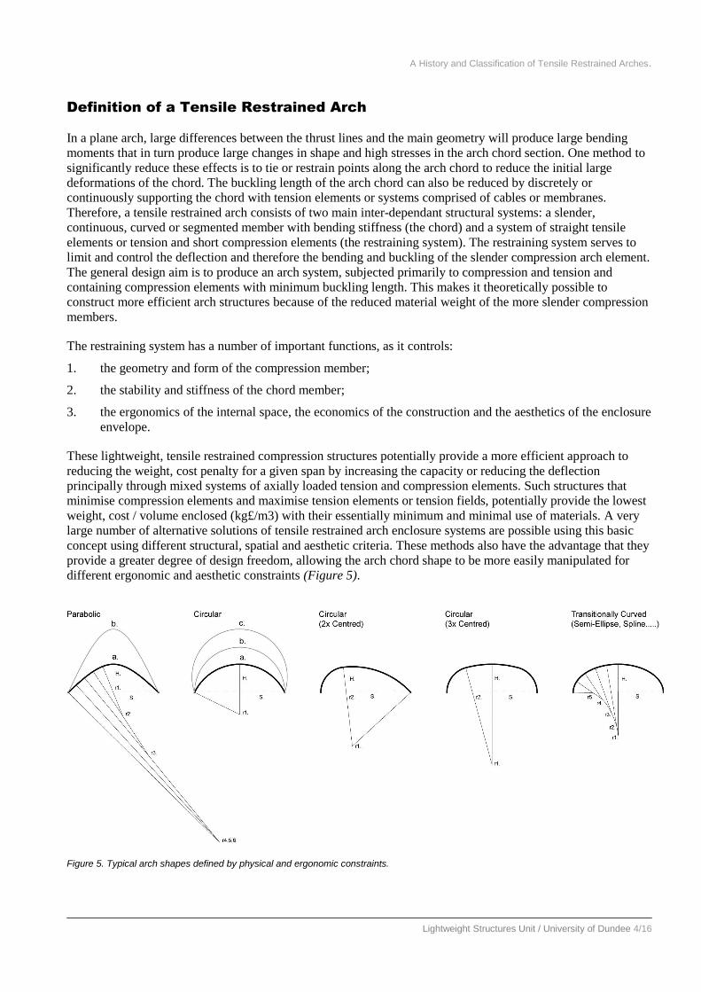
provide a greater degree of design freedom, allowing the arch chord shape to be more easily manipulated for
different ergonomic and aesthetic constraints (Figure 5).
Figure 5. Typical arch shapes defined by physical and ergonomic constraints.
A History and Classification of Tensile Restrained Arches.
Lightweight Structures Unit / University of Dundee 5/16
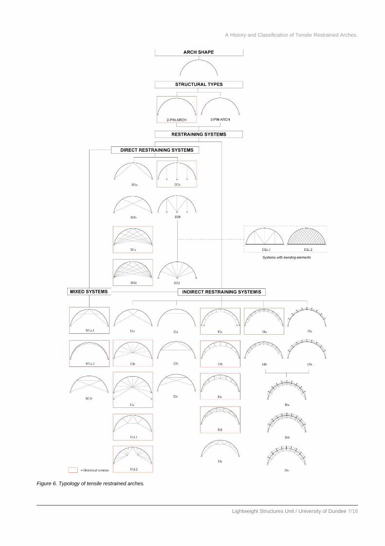
Types of Tensile Restrained Arch
The restraining system can take many different forms depending on the loading, the ergonomic requirements of
the enclosure, aesthetics, economics and buildability. The restraining system may be located inside, outside or
on both sides of the compression member. However, tensile restrained arches can be classified first by the
configuration of the tensile restraining system according to the supports. This produces three main groups or
classes, namely: Direct, Indirect and Mixed Systems. These can be further sub-divided by examining the form
or arrangement of the restraining system elements in relation to the arch chord member, producing a number of
generic sub-groups, each exhibiting unique behavioural and physical characteristics. These are shown here in
the form of abstract models (Figure 6.). Within each model a range of specific tensile restrained arches can be
produced, retaining the overall characteristics of the typological group, by varying common parameters, such as
arch chord discretisation and the number, length and angle of restraining elements.
Direct Systems (D)
Direct systems control the displacement of points on the arch chord by either:
D1. Using tie members connected directly between these points and the arch supports. Typically, a basic
system will employ two restraining elements connecting the two supports to the centre (crown) of the
arch (a) or to two points spaced equidistantly about the centre (b). In the latter the tension members will
overlap but will not physically intersect one another. More sophisticated systems will employ a number of
discrete (overlapping) restraining members connected to points spaced around the arch chord
circumference (c & d);
D2. Using tie members connected directly between the arch chord and a number of additional supports.
Typically, these systems can take two forms. The first employs vertical or radial restraints connected
between points on the arch circumference and a support located between the main arch supports. The
support(s) may be discrete (a & b) or a bending resistant member such as a beam (c). The second employs
a centrally located support or ‘hub’ (similar to a bicycle wheel) and a number of radially spaced restraints
connected between the hub and points on the arch chord (d).
Indirect Systems (I)
Indirect systems control the displacement of points on the arch chord by:
I1. Using tie members connected between these points and one or more ‘non-fixed’ hubs. The hub may be
located near the origin or centre of the arch (b) or by increasing the height of the hub relative to the origin
to provide improved internal ergonomics (a & d). The stiffness of the system can be improved by
additional ties connected between the hub and additional supports independent of the arch chord (c).
I2. Using tie members connected between pairs of points on the arch set at regular intervals around its
circumference. A simple system will consist of a single horizontal tie connected between two points
spaced equidistantly about the arch centre (a). A more sophisticated system with increased discretisation
using overlapping ‘restraints’ connected between every other adjacent point shortens the buckling length
of the arch but also reduces the effective depth between the tie(s) and the arch, eventually reducing the
trussing effect. An alternative approach is to connect pairs of points on opposite sides of the arch (c);
I3. Using an internal curved tension cable connected indirectly to the arch chord using either radial members,
diagonal members or both. There are two principal approaches. The first employs an inwardly parallel
tension cable connected to the arch by radials of equal length with supports independent of the arch chord
supports (a). If this system is loaded on the arch chord, the restraining system will provide only nominal
additional contribution to the stability of the chord. However, if the loading is applied to the arch chord
via the restraining system (as in The Pavilion of the Future, Seville, 1998) a constant radial, inward
prestress force will be produced so that the thrust line in the arch will follow exactly the shape of the arch
provided it is of semi-circular shape. The second employs an inwardly disposed tension cable connected
to the arch chord supports at the ends and to the arch chord at intermediate points by radials and or
diagonals increasing in length towards the arch centre (b to e). The shape of the inside cable needs to be
determined by balancing the member forces in the arch for the dominant load case.

A History and Classification of Tensile Restrained Arches.
Lightweight Structures Unit / University of Dundee 6/16
I4. Using inwardly, radial compression struts and diagonal tension members connected between the arch
chord and the ends of the compression struts or with the addition of a continuous, inwardly disposed cable
connected to the arch chord supports and to the ends of the radial struts (a & b).
I5. Using outwardly, radial compression struts and diagonal tension members connected between the arch
chord and the ends of the compression struts or with the addition of a continuous, outwardly disposed
cable connected to the arch chord supports and to the ends of the radial struts (a & b).
I6. Hybrid systems combining I4 & I5 above. These systems have the advantage of being able to resist
bending in both directions due to the presence of the two circumferential cable elements either of which
can take tension depending on the sense of the bending applied.
Mixed Systems (M)
These hybrid systems employ both direct and indirect restraining systems in a single inter-dependant system
(M1a & M1b). Different systems are usually combined to provide different forms of enclosure (Eurolille) and to
provide improved stability under different load cases.
A History and Classification of Tensile Restrained Arches.
Lightweight Structures Unit / University of Dundee 7/16
Figure 6. Typology of tensile restrained arches.

A History and Classification of Tensile Restrained Arches.
Lightweight Structures Unit / University of Dundee 8/16
A Structural Comparison of Arch Restraining Systems
The following numerical study involves applying typical environmental loads to each of the principal restrained
arch types while monitoring their behaviour. In some cases a number of variations of the restraining system type
have been used to ascertain the effects of changing the discretisation and geometry of the basic system. For the
purposes of this study, the analysis uses a semi-circular arch chord member and non-optimised restraining
system geometry and is restricted to members composed of elastic material such as steel. The variety of systems
considered enables a general structural comparison to determine the relative efficiency of the different generic
restraining strategies.
Section Properties
All arches have a common circular profile with a span of 30m and two hinged supports. The arches have been
designed so that the resulting member sizes used enables a direct comparison of the results in all cases. The
cross-sections used are: Circular Hollow Section 225 x 10 in the arch chord which is modelled as a continuous
beam element. The tie members are solid bar with 40mm diameter and are modelled using single elements
capable only of transmitting tension loads. Compression struts in types I4,5 & 6 are 100x5 CHS; these members
are allowed to carry both tension and compression. Tension and compression members are similar in area but
have not been designed. Deformation out of plane is prevented as the arch is assumed to be fully restrained in
the lateral direction. All arches have been analysed elastically while considering geometrical non-linearity using
the finite element software package Oasys. A limited parametric study was included for some restraining system
types to show the effects of varying member discretisation. Arches have been analysed with and without
prestress in their tensile restraining elements to enable the effect of the prestress to be seen. The prestress
applied has not been optimised for the different forms but kept at a constant value.
Load Cases
The load conditions cover the range of common design loads. All structures are subjected to six basic loading
conditions as follows (Figure 7.):
LC1. Dead load only – a uniform load covering the whole length of the arch;
LC2. Dead + snow – snow loading according to EC;
LC3. Dead + snow (asymmetric) – snow load rotated around arch to simulate effects
of wind driven snow;
LC4. Dead + wind – wind pressure taken from experimental study of flow over a hemi-
cylinder;
LC5. Dead + wind + snow; LC6. Dead + wind + snow (ass)
Figure 7. Load cases without prestress.

A History and Classification of Tensile Restrained Arches.
Lightweight Structures Unit / University of Dundee 9/16
In addition, seven load cases where the elements of the restraining system are prestressed to 10kN in tie bracing
members, have been analysed:
LC7. Dead + prestress –;
LC8. Dead + snow + prestress;
LC9. Dead + snow (ass) + prestress;
LC10. Dead + wind + prestress;
LC11. Dead + snow + wind + prestress;
LC12. Dead + snow (ass) + wind + prestress;
LC13. Prestress only.
Analyses of the Results
Graphical Output
(Figure 8.) compares deflection in the arch for the load cases that produce the maximum deflection in the
different systems as this is an important objective in using a restraining system. For the majority of cases the
worst load case combination is dead load plus asymmetric snow load (LC3). For visual comparison the figure
shows the results for LC3. In the few cases where this is not the critical case, this is noted below in the diagram
(CLC2) and is not shown visually. For the purposes of this analysis it was beneficial to first compare the
behaviour of the restrained but un-prestressed systems so that a comparison could be made to the effects of
prestressing (Figure 9.).
System I1b without prestress (LC3) System I1b with prestress (LC9)
Figure 9. Comparison of the behaviour of system I1b with and without prestress.
The diagrams show the deflected shape of the arch normally to a scale of x10 (D1d [x10]) but for those cases
where deflection is large the true deflected shape is shown (D1a [x1]). The axial stress is indicated by the colour
of the deflected shape of the arch as indicated in the colour scale at the top of the diagram. The bending moment
is shown by the blue shaded areas with the magnitude indicated by the distance from the arch centre line. The
odd shape of the BMD in the two-pin plane arch is caused by the overlap of the sections of the moment diagram
due to the curvature of the arch (the moment diagram does not peak as might be taken from the diagram at first
glance).

A History and Classification of Tensile Restrained Arches.
Lightweight Structures Unit / University of Dundee 10/16
Figure 8. Comparison of the behaviour of different arch restraining systems under load case LC3.

A History and Classification of Tensile Restrained Arches.
Lightweight Structures Unit / University of Dundee 11/16
Stresses and Deflection
In load case LC3 (without prestress) the maximum axial stress for all the arches ranges from 25 N/mm2
minimum to 109 N/mm2 maximum (Figure 10). In most cases the axial stress increases towards the arch
supports as would be expected. However, there are a number of cases particularly the truss type systems (I4 to
I6), where the trussing action of the bracing system resists the bending by inducing a tensile force in the
circumferential tensile element(s) and a corresponding increase in compressive stress in the arch rib.
The bending stress is related to the curvature of the member which is dependant on the deflected shape of the
arch rib. The value and position of the maximum bending stress changes depending on the restraining system
type and the way in which it controls the deflection. For instance in type I4a, the internal bracing members in
the top part of the arch work to maintain the shape of the rib above the quarter points of the arch while the rib
below these points is effectively unrestrained and thus deflection and bending develops here. With type I5a
under the same load case, the external bracing stiffens the two outer sections of the arch but fails to stiffen the
Figure 10. Comparison of the deflection, bending moment, axial stress and efficiency of different arch restraining systems under load case LC3.
A History and Classification of Tensile Restrained Arches.
Lightweight Structures Unit / University of Dundee 12/16
central section where deflection and bending develop. In type I6a where these systems are combined the inner
and outer bracing systems complement each other to stiffen the rib where needed. In systems such as D1d and
I1b that use direct and hub restrained systems, outward movement of the arch is directly prevented and inward
movement is indirectly prevented as this can only happen if the restraining members extend significantly or the
arch rib snaps through between restrained points. In these systems the stiffness of the arch tends to increase with
an increase in the number of restraining members. However, it can be seen that in simple systems such as D1b
and M1a which control the crown and quarter points of the arch rib, significant improvements in arch stiffness
are produced. While the latter systems are more efficient in structural terms than truss type systems they are less
effective in terms of space utilisation, but this constraint does not apply in all applications.
Prestress
In the cases that have been analysed with prestress it was found that this always reduced the deflection which in
turn reduced the bending stress and generally the axial stress in the arch chord increased. Although in the
prestressed load cases the systems would need to be optimised to gain maximum benefit, it can be seen that the
prestress had a lower influence on arch stiffness compared to the effect of increasing tension member
discretisation and changes in the general restraining system geometry. The effectiveness of pretressing is
dependant on the geometry of the restraining system, number of restraining members and the balance in
stiffness of its members. In reality, in such systems prestress would almost certainly be used and applied in such
a way as to maintain the desired profile of the arch under dead load only.
Critical Load Case
In systems D1b, I1b and I5a, LC4 is the critical load case. In each case the upward suction on the top section of
the arch rib causes the lower left section to straighten (the bracing is unable to resist this action) and in I1b and
I5a, allowing the arch to rotate about the right support. In D1b only a proportion of the arch is able to rotate due
to the restraining action of the second restraining member.
In systems D1c, D1d, D2b and D2d, LC2 is the critical load case. In all these systems the central half of the arch
rib carries the vast majority of the loading but the restraining members in this area are unable to provide direct
support. In D2b the only restraint is provided by the diagonal members at the quarter points of the arch rib. The
behaviour of the other systems is similar with the restraint being provided by the lower diagonals at the quarter
and eighths points on the arch rib.
Efficiency
The general objective of a restrained arch system is to increase the stiffness of a comparatively thin compression
member using tensile restraining elements while reducing the weight, cost penalty of the overall system. As it
was not practical in this study to derive a reproducible assessment of cost a general structural comparison was
used to determine relative efficiency. This was considered in two ways, namely:
1 / (total member length x deflection);
1 / (total number of members x deflection).
(Where the deflection is the observed maximum deflection of the arch chord.)
The efficiency based on member lengths takes account of the total amount of material used in the restraining
system which directly relates to the structural efficiency of the system. However a more realistic appreciation
can be gained by considering the complexity of the system which relates to the total number of members and
connections required between members. This gives a better indication of the economics of the construction
when joint complexity, end details, manufacture and buildability are considered. End connections are a major
cost in the restraining system because these usually require specialised components and manufacture to allow
fine adjustment of member lengths needed for construction tolerances and prestressing.
Material Content:
A History and Classification of Tensile Restrained Arches.
Lightweight Structures Unit / University of Dundee 13/16
When considering material content, the different systems can be divided into four main groupings, namely:
Group 1 – Systems D1c, D1d, and D2d. These systems give a high value because the arch is directly restrained
from supports using minimum material.
Group 2 – Systems I2c and I1c. I2c is a simple indirect system with both quarter and eighth points restrained
providing adequate stiffness using little material. I1c performs less well because the hub is not held as rigidly as
D2d (above) resulting in a greater deflection and it also contains more members. I1c is more efficient than I1b
(below) because, even though there is more material in the system, the reduction in deflection more than
compensates for this.
Group 3 – Systems D1b, D2b, I1b, I1d.2, I2b, I3c, I3e, I4b, I5a, I5b, I6a, I6b, I6c, M1a.1 and M1b. This group
comprises two sub-groups, namely simple systems using little material but providing adequate stiffness and
more complex systems such as some of the stiffened beams which rank lower here due to the amount of material
used.
Group 4 – This group is dominated by systems that provide little diagonalisation despite using significant
amounts of material or systems that use minimal material but the system geometry provides little restraint.
Complexity:
When considering complexity, the different systems can also be divided into four main groupings, namely:
Group 1 – System D1c. In this example the arch chord is finely discretised using a direct restraining system. It is
comparatively simple and uses well disposed members that prevent significant changes in shape of the arch
chord under different loads.
Group 2 – Systems D1d, D2d. System D1d is less effective than D1c (above) because the extra members
provide only minimal additional stiffening but increase the complexity. D2d provides fine discretisation of the
arch chord using a comparatively small number of members that are directly connected to a fixed hub making it
stiffer than the indirect hub restrained systems below that use even more members.
Group 3 – D1b, I1b, I1c, I2c, M1a.1, M1b. Whilst these are simple systems, the lack of stiffness provided by the
restraining system cannot compensate for the simplicity.
Group 4 – This group is dominated by stiffened beam systems, which although providing significant stiffening
score lowest due to the very high number of members in the system.
Ergonomics
The ergonomics of the different systems are another important factor in the choice of restraining system. This is
usually a compromise between efficiency, functionality and aesthetics. While it is not possible to quantify
ergonomics a number of important issues were observed. The ergonomics of the enclosure are affected by the
compression chord shape, the position of the restraining system (above or below the arch chord) and the type of
restraining system (chord restrained, trussed, vertical / horizontal / diagonal tied or radial tied). The impact these
factors have depends primarily on the use of the enclosure. For example if it is necessary to utilise the volume
enclosed by the arch (such as in a shelter system) then truss type systems, chord braced and multi-hub radial
braced systems are more beneficial. In most atria roofs it is unlikely the internal volume enclosed by the arch
will have a functional requirement which allows the space to be used as a structural zone, making it more
efficient to use radial braced systems in these applications.
DESIGN TRENDS
A very large number of alternative solutions of tensile restrained arch enclosure systems are possible by
applying the basic restraining system types using different structural, spatial and aesthetic criteria. Historically,

A History and Classification of Tensile Restrained Arches.
Lightweight Structures Unit / University of Dundee 14/16
restraining systems were used in many different forms depending on the loading, ergonomic, aesthetic,
economic and buildability requirements of the enclosure. The first examples were developed during the period
1889 – 1923 to provide efficient, wide-span enclosures principally for train sheds during the railway
construction boom. The construction of so many different solutions was made possible due to the availability of
new materials (cast and wrought iron) having higher tensile strengths than timber and the ability to form these
into discrete, thin, linear and curved members that were also easier to connect together. The detail design of
early restrained arch systems adapted timber jointing technology and applied this to the element connection
design without fully realising the potential of the new materials. However, known concerns with attaining
consistent material properties (particularly tensile strength) and the unfamiliar nature of the materials meant that
many of these early examples were over-structured with additional elements being used to help reduce material
stresses. This is particularly evident in arch chord cross-section designs which rely on complex fabricated truss
sections comprised of short members to reduce bending stresses in the chord section. Similarly the tensile
restraining elements are comparatively short probably due in part to the difficulties inherent in fabricating long
elements of consistent mechanical properties in wrought iron. As a result these early tensile restrained arches
failed to fully capitalise on their true structural and aesthetic potential which in some cases produced inelegant
and visually confusing solutions.
One of the principle differences between the early restrained arches and the later 20th Century examples has
been in the development of high strength constant section steel profiles and high strength steel cables and their
connections. These new materials and more sophisticated fabrication processes permitted the development of
improved member section shapes to take account of the higher tensile strengths of the material. Modern,
numerically based, cold forming and cambering processes now permit standard structural sections of various
dimensions to be curved to single or multi-centred curves on the major (y-y) axis producing smooth accurate
bends whilst maintaining the section geometry, essential for architectural steelwork. In parallel, modern welding
technologies have significantly contributed to improved mechanical and aesthetic design allowing the
fabrication of continuous chord sections without needing bulky and unsightly splice plates. These developments
allow the arch chord to be easily and economically curved to a desired enclosure cross-section, while
maintaining a high level of bending stiffness and consistent jointing between chord sections without the jointing
becoming a dominant feature in the member profile. High strength and stiffness steel rope technologies
currently used in the majority of contemporary restraining systems are made in a wide range of cross-section
diameters and are low weight, visually light and provide consistent properties. These materials coupled with a
range of standard end-fitting systems, make it easier and more economical to form connections between
elements permitting much higher levels of pre-stressing. These reasons account in part for the recent rise in the
large number of more complex truss type restraining systems. Truss systems combining thin arch chords
carrying principally axial compression and complex triangulated restraining systems carrying principally tension
produces efficient structural solutions with reduced weight, increased stiffness and potentially lower costs. They
have the added advantage that they provide a greater degree of design freedom as the main geometry of the arch
chord can be more easily manipulated for different ergonomic and aesthetic constraints while being able to
control the stiffness of the structure through the use of an appropriate tensile restraining system that does not
impede significantly on the internal space of the enclosure. With the very recent advances in new organic
polymeric fibre technologies and other high strength materials, particularly composites and metal alloy
technologies it is arguable that another step-change in the design of lightweight filigree tension restrained
structures is possible. However, to date these materials have largely been used as substitutes for existing
materials without fully capitalizing on their intrinsic properties or potentials.
Conclusions
The general design aim of a tensile restrained arch is to produce an arch system, subjected primarily to
compression and tension and containing compression elements with minimum buckling length. This makes it
theoretically possible to construct more efficient arch structures by minimising compression elements and
maximising tension elements (or tension fields), potentially providing low weight, cost / volume enclosed (kg £
/ m3). Restraining systems can take many different forms ranging from the simple to the complex. Different
systems may be located on the outside, inside or both sides of the compression member. However, it was found
that a convenient generic method for the classification of the different examples was to group these according to

A History and Classification of Tensile Restrained Arches.
Lightweight Structures Unit / University of Dundee 15/16
their relationship to the arch supports, providing three main groups of systems, namely: Direct, Indirect and
Mixed Systems.
The structural analysis a range of typical environmental loads provided a general structural comparison and
determined the relative efficiency of the different generic restraining strategies. A number of specific
conclusions can be made:
a. A first major improvement to the plane arch can be made by restraining the quarter points and then the
centre point of the arch using comparatively simple restraining systems.
b. Directly and indirectly restrained systems utilising radial and hub types are more efficient and stiffer than
any other group as they provide multiple points of restraint to the arch chord but achieve this with the
minimum of members.
c. Truss type systems showed similar if not improved stiffness to the hub type systems but at the expense of
number of members. A number of these systems can be designed to optimise multiple load cases due to
the restraining systems being on both sides of the member.
d. In all cases prestress marginally improved the performance of the individual system and it would be
expected that further improvement could be made if the prestress was optimised.
e. Deflection of the arch chord generally reduces with an increase in discretisation of the restraining system
with the exception being the chord braced system M1a.1/2. While the system stiffness usually increases
with the number of members, the efficiency doesn’t necessarily increase as the deflection of some
systems with a high number of elements can be bigger than other systems with fewer elements. It follows
then that the efficiency is determined by a balance between the number of members and the arrangement
of these elements in relation to the arch chord and supports.
Ergonomically, the arch restraining systems can be organised into two main categories, namely: systems in
which the restraining elements occupy the majority of the internal space below the arch chord; and systems in
which the restraining system closely follows the profile of the arch chord. The former comprise direct radial and
hub retrained systems which are normally used in applications such as atria roofs where the internal volume
within the arch profile is not utilised functionally. These systems tend to be more efficient than truss systems,
chord braced and multiple hub systems although the latter permit a more flexible use of the space enclosed by
the arch chord. (6687)
References
[1] Daintith, J., & Nelson, R.D., (Ed.), Dictionary of Mathematics, Penguin Books, London, 1989.
[2] Herrmann J.: Tragverhalten zugausgesteifter Bögen, Diploma Thesis, Institut für Tragwerksentwurf und Konstruktion, Prof. Dr.-Ing. J. Schlaich, Universität Stuttgart 1994
[3] Hooke, R., Description of Helioscopes, and some other Instruments, London, 1676.
[4] Graefe, R.(Hrsg), 1989. Zur Geschichte des Konstruierens, DVA, Stuttgart.
[5] Graefe R.; M. Gappoev, O.; Pertschi.; 1990, Vladimir G. Suchov 1853-1939, Die Kunst der sparsamen Konstruktion DVA, Stuttgart.
[6] Mislin, M., 1988, Geschichte der Baukonstruktionen und der Bautechnik – Von der Antike bis zur Neuzeit- Eine Einführung, Düsseldorf : Werner Verlag.
[7] Schlaich J.: Bahnsteighallen leicht, weit, hell – Lehrter Bahnhof in Berlin, In: Verkehrsbauten, published in the series “Geschichte des Bauingenieurwesens, Lehrstuhl für Baukonstruktion , Technische Universität München 2000
[8] Rice, P.: 1994, An engineer imagines / Peter Rice, Artemis, London Zürich München.
[9] Sasek, L., Low Loader – Forty percent more efficient than a conventional bowstring arch bridge, the world’s first long-span ‚network arch‘ structure is being build in Prague, Bridges Special:Troja Bridge, New Civil Engineer, 2012
[10] Burford, N.K. and Smith, F.W.,

A History and Classification of Tensile Restrained Arches.
Lightweight Structures Unit / University of Dundee 16/16
[11] Burford, N.K: 2004, The Use of a Lightweight, Transformable, Fabric Web Restrained Arch in Rapidly Deployed Mobile Shelters, PhD Dissertation, University of Dundee.
[12] Burford N.K.; Gengnagel C.; Smith F.W, 2006, Restrained Arches, Stahlbau (Structural Steelwork), Ernst + Sohn, Wiley-VCH Verlag GmbH + Co, Berlin, 75. Jahrgang, Heft 8, ISSN 0038-9145).
[13] Gengnagel, C. 2005, Mobile Membrankonstruktionen, Dissertation, Schriftenreihe des Lehrstuhls für Tragwerksplanung Band 12, Technische Universität München, ISBN 3-938660-07-4.
[14] Burford N.K.; Gengnagel C. and Smith F.W, Evolution of Arches as Lightweight Structures, Conf. Proc. 3rd
International Congress Construction History, Cottbus, Germany, May 2009.