a guide to optimizing spray injector performance · a guide to optimizing spray injector...
TRANSCRIPT

Spray Nozzles
Spray Control
Spray Analysis
Spray Fabrication
A Guide to Optimizing Spray Injector Performance Specification, Design and Fabrication
��
Spray Injectors: Critical but Often
Overlooked Components
At the heart of any spray application is the spray nozzle. Often the smallest component in a spray system, the nozzle is designed to yield very precise performance. Even small deviations in performance can result in serious process quality problems, unscheduled downtime and thousands of dollars of increased operating costs.
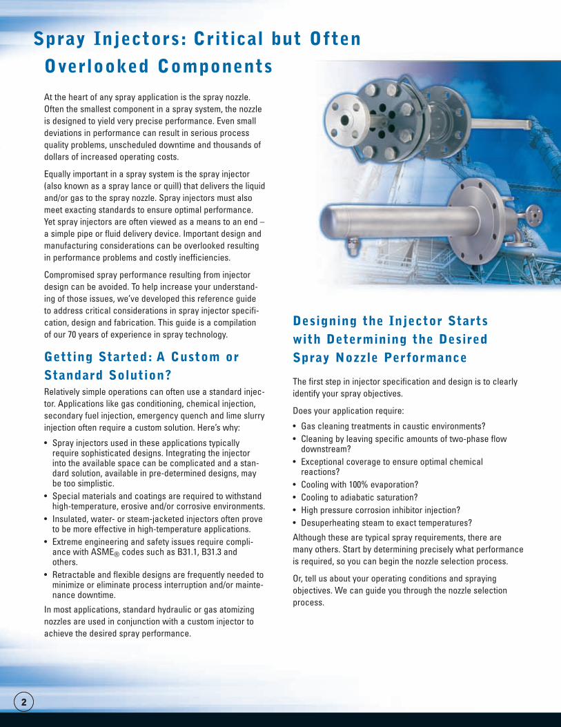
Equally important in a spray system is the spray injector (also known as a spray lance or quill) that delivers the liquid and/or gas to the spray nozzle. Spray injectors must also meet exacting standards to ensure optimal performance. Yet spray injectors are often viewed as a means to an end – a simple pipe or fluid delivery device. Important design and manufacturing considerations can be overlooked resulting in performance problems and costly inefficiencies.
Compromised spray performance resulting from injector design can be avoided. To help increase your understand-ing of those issues, we’ve developed this reference guide to address critical considerations in spray injector specifi-cation, design and fabrication. This guide is a compilation of our 70 years of experience in spray technology.
Getting Started: A Custom or Standard Solution?Relatively simple operations can often use a standard injec-tor. Applications like gas conditioning, chemical injection, secondary fuel injection, emergency quench and lime slurry injection often require a custom solution. Here’s why:
• Spray injectors used in these applications typically require sophisticated designs. Integrating the injector into the available space can be complicated and a stan-dard solution, available in pre-determined designs, may be too simplistic.
• Special materials and coatings are required to withstand high-temperature, erosive and/or corrosive environments.
• Insulated, water- or steam-jacketed injectors often prove to be more effective in high-temperature applications.
• Extreme engineering and safety issues require compli-ance with ASME® codes such as B31.1, B31.3 and others.
• Retractable and flexible designs are frequently needed to minimize or eliminate process interruption and/or mainte-nance downtime.
In most applications, standard hydraulic or gas atomizing nozzles are used in conjunction with a custom injector to achieve the desired spray performance.
Designing the Injector Starts with Determining the Desired Spray Nozzle Performance
The first step in injector specification and design is to clearly identify your spray objectives.
Does your application require:
• Gas cleaning treatments in caustic environments?• Cleaning by leaving specific amounts of two-phase flow
downstream?• Exceptional coverage to ensure optimal chemical
reactions?• Cooling with 100% evaporation?• Cooling to adiabatic saturation?• High pressure corrosion inhibitor injection?• Desuperheating steam to exact temperatures?
Although these are typical spray requirements, there are many others. Start by determining precisely what performance is required, so you can begin the nozzle selection process.
Or, tell us about your operating conditions and spraying objectives. We can guide you through the nozzle selection process.
�
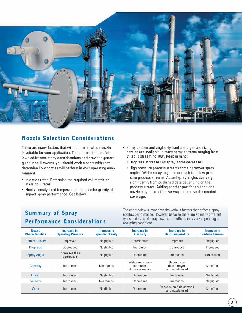
NozzleCharacteristics
Increase inOperating Pressure
Increase inSpecific Gravity
Increase inViscosity
Increase inFluid Temperature
Increase inSurface Tension
Pattern Quality Improves Negligible Deteriorates Improves Negligible
Drop Size Decreases Negligible Increases Decreases Increases
Spray Angle Increases thendecreases Negligible Decreases Increases Decreases
Capacity Increases DecreasesFull/hollow cone –
increasesFlat – decreases
Depends onfluid sprayed
and nozzle usedNo effect
Impact Increases Negligible Decreases Increases Negligible
Velocity Increases Decreases Decreases Increases Negligible
Wear Increases Negligible Decreases Depends on fluid sprayedand nozzle used No effect
�
There are many factors that will determine which nozzle is suitable for your application. The information that fol-lows addresses many considerations and provides general guidelines. However, you should work closely with us to determine how nozzles will perform in your operating envi-ronment.
• Injection rates: Determine the required volumetric or mass flow rates.
• Fluid viscosity, fluid temperature and specific gravity all impact spray performance. See below.
• Spray pattern and angle: Hydraulic and gas atomizing nozzles are available in many spray patterns ranging from 0° (solid stream) to 180°. Keep in mind:• Drop size increases as spray angle decreases.• High pressure process streams force narrower spray
angles. Wider spray angles can result from low pres-sure process streams. Actual spray angles can vary significantly from published data depending on the process stream. Adding another port for an additional nozzle may be an effective way to achieve the needed coverage.
Nozzle Selection Considerations
The chart below summarizes the various factors that affect a spray nozzle’s performance. However, because there are so many different types and sizes of spray nozzles, the effects may vary depending on operating conditions.
Summary of Spray
Performance Considerations
�
• Solids content: Determine the percentage of solids in the fluid being sprayed. If solids content is high: • Consider using Maximum Free Passage
(MFP) nozzles to minimize clogging.• Consider using nozzles with anti-bearding
designs to minimize material build-up on the exit orifices and nozzle tip.
• Consider using erosion-resistant nozzles made from ceramics or hardened steels.
• Drop size: In many processes the goal is 100% evaporation, and this requires precise control of drop size. Critical factors to con-sider:• Drop size refers to the size of the individ-
ual drops in the spray pattern. Each spray pattern consists of a range of drop sizes. This range is called drop size distribution.
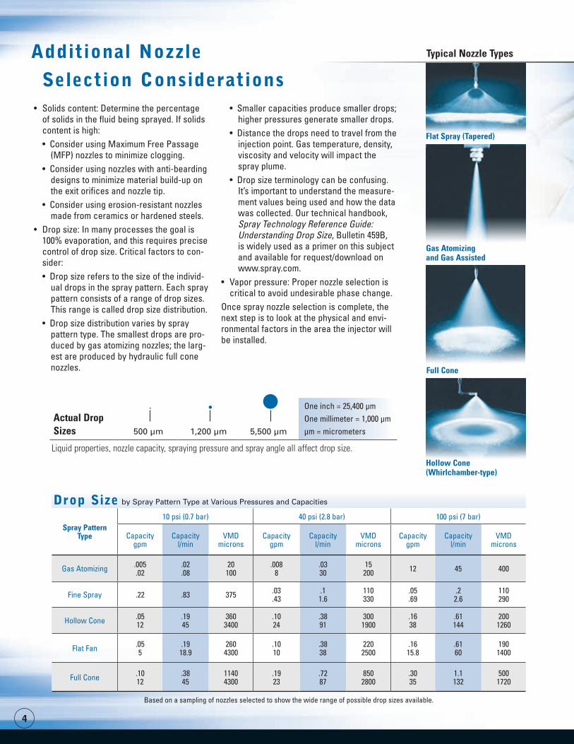
• Drop size distribution varies by spray pattern type. The smallest drops are pro-duced by gas atomizing nozzles; the larg-est are produced by hydraulic full cone nozzles.
• Smaller capacities produce smaller drops; higher pressures generate smaller drops.
• Distance the drops need to travel from the injection point. Gas temperature, density, viscosity and velocity will impact the spray plume.
• Drop size terminology can be confusing. It’s important to understand the measure-ment values being used and how the data was collected. Our technical handbook, Spray Technology Reference Guide: Understanding Drop Size, Bulletin 459B, is widely used as a primer on this subject and available for request/download on www.spray.com.
• Vapor pressure: Proper nozzle selection is critical to avoid undesirable phase change.
Once spray nozzle selection is complete, the next step is to look at the physical and envi-ronmental factors in the area the injector will be installed.
Additional Nozzle
Selection Considerations
Typical Nozzle Types
by Spray Pattern Type at Various Pressures and Capacities
Spray Pattern Type
10 psi (0.7 bar) 40 psi (2.8 bar) 100 psi (7 bar)
Capacity gpm
Capacity l/min
VMD microns
Capacity gpm
Capacity l/min
VMD microns
Capacity gpm
Capacity l/min
VMD microns
Gas Atomizing .005.02
.02
.0820100
.0088
.0330
15200 12 45 400
Fine Spray .22 .83 375 .03.43
.11.6
110330
.05
.69.2
2.6110290
Hollow Cone .0512
.1945
3603400
.1024
.3891
3001900
.1638
.61144
2001260
Flat Fan .055
.1918.9
2604300
.1010
.3838
2202500
.1615.8
.6160
1901400
Full Cone .1012
.3845
11404300
.1923
.7287
8502800
.3035
1.1132
5001720
Based on a sampling of nozzles selected to show the wide range of possible drop sizes available.
Drop Size
Actual Drop Sizes 500 µm 1,200 µm 5,500 µm
One inch = 25,400 µmOne millimeter = 1,000 µmµm = micrometers
Liquid properties, nozzle capacity, spraying pressure and spray angle all affect drop size.
Flat Spray (Tapered)
Gas Atomizing and Gas Assisted
Hollow Cone (Whirlchamber-type)
Full Cone
�
Injector Specification and Design ConsiderationsConsider the following when establishing your requirements:
• What is the size of the duct, vessel or tower? This will influence the number of nozzles and nozzle placement.
• Are there bends in the duct? Elbows can cause secondary flow profiles that negatively impact performance.
• What is the proximity to upstream and downstream equip-ment? Process problems and/or damage can result if the spray plume is too close to other equipment.
• What are the operating conditions? Gas and liquid properties affect spray plume distance. Temperature and corrosiveness will have an impact on materials of construction.
• What is the composition of the liquid being sprayed? This will affect the materials of construction.
• What is the fluid service category? This may require the injector to meet stringent design requirements for safety.
• Will the spray be co-current or counter-current? Co-current sprays have longer residence times, may produce smaller drops and enable use of a wider spray angle. Counter-current sprays may result in more build-up, vibration, stress on injec-tor pipes, larger drops and wetting.
• What connections are required? Welded, flanged, threaded? • Can the optimal injector position be determined prior to instal-
lation? If not, a flexible design for easy adjustment is an option. • How often can the injector be serviced? Are there any spe-
cial considerations? Retractable lances can eliminate or minimize process downtime. Also, if regular maintenance is not feasible, 100% evaporation and purging of air are likely required to reduce the risk of sludge formation.
• What is the desired service life of the injector prior to replacement? This may impact materials of construction and design.
• What is the preventive maintenance (PM) schedule? Injector weight can be reduced and attachments made to accelerate changeout.
There are many other considerations that are specific to the process. Working with us during the design phase will help achieve the best possible performance at the lowest possible cost.
Typical Nozzle Types
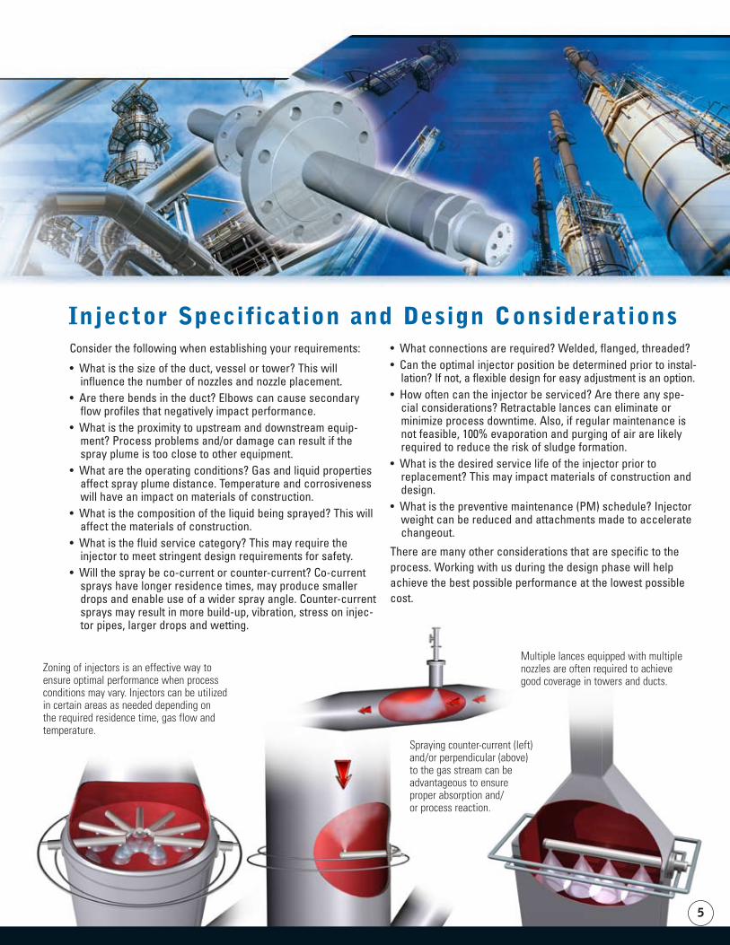
Zoning of injectors is an effective way to ensure optimal performance when process conditions may vary. Injectors can be utilized in certain areas as needed depending on the required residence time, gas flow and temperature.
Spraying counter-current (left) and/or perpendicular (above) to the gas stream can be advantageous to ensure proper absorption and/or process reaction.
Multiple lances equipped with multiple nozzles are often required to achieve good coverage in towers and ducts.
�
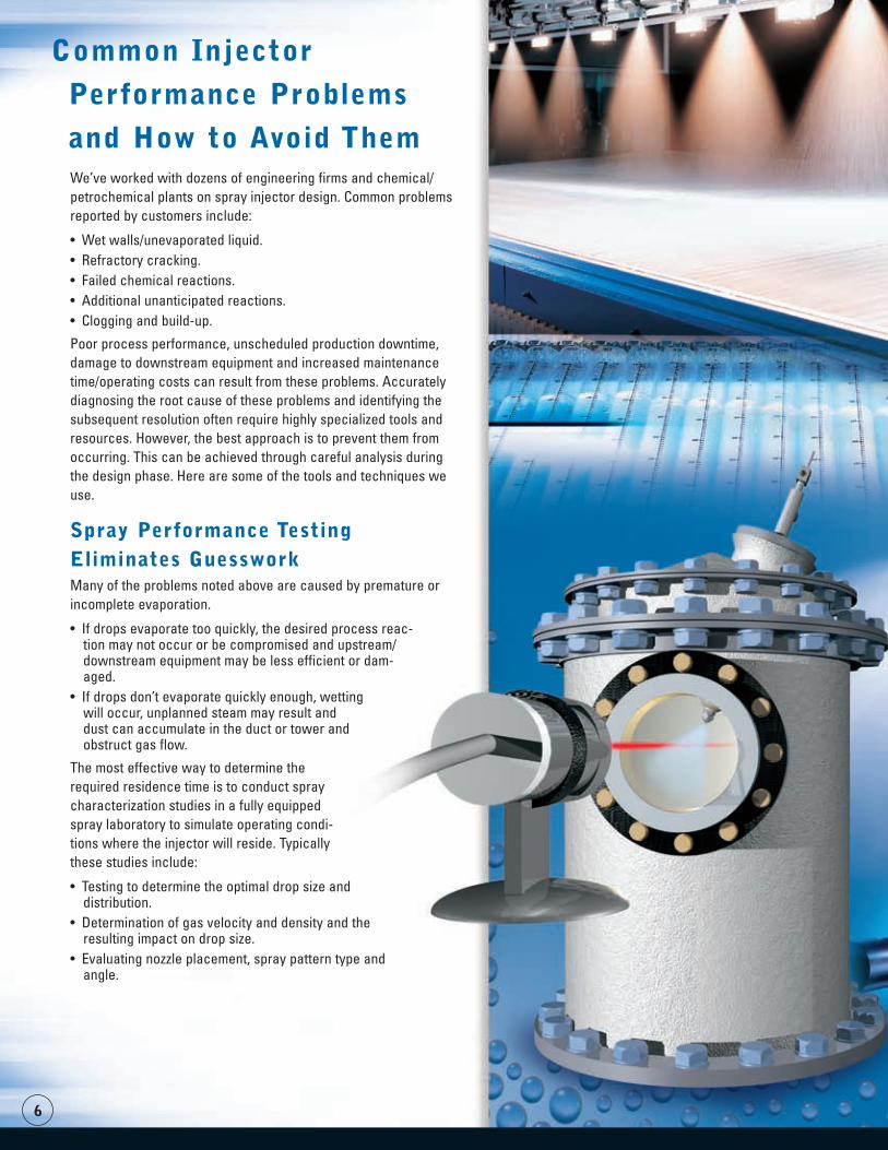
Common Injector
Performance Problems
and How to Avoid ThemWe’ve worked with dozens of engineering firms and chemical/ petrochemical plants on spray injector design. Common problems reported by customers include:
• Wet walls/unevaporated liquid.• Refractory cracking.• Failed chemical reactions.• Additional unanticipated reactions.• Clogging and build-up.
Poor process performance, unscheduled production downtime, damage to downstream equipment and increased maintenance time/operating costs can result from these problems. Accurately diagnosing the root cause of these problems and identifying the subsequent resolution often require highly specialized tools and resources. However, the best approach is to prevent them from occurring. This can be achieved through careful analysis during the design phase. Here are some of the tools and techniques we use.
Spray Performance Testing Eliminates Guesswork Many of the problems noted above are caused by premature or incomplete evaporation.
• If drops evaporate too quickly, the desired process reac-tion may not occur or be compromised and upstream/downstream equipment may be less efficient or dam-aged.
• If drops don’t evaporate quickly enough, wetting will occur, unplanned steam may result and dust can accumulate in the duct or tower and obstruct gas flow.
The most effective way to determine the required residence time is to conduct spray characterization studies in a fully equipped spray laboratory to simulate operating condi-tions where the injector will reside. Typically these studies include:
• Testing to determine the optimal drop size and distribution.
• Determination of gas velocity and density and the resulting impact on drop size.
• Evaluating nozzle placement, spray pattern type and angle.
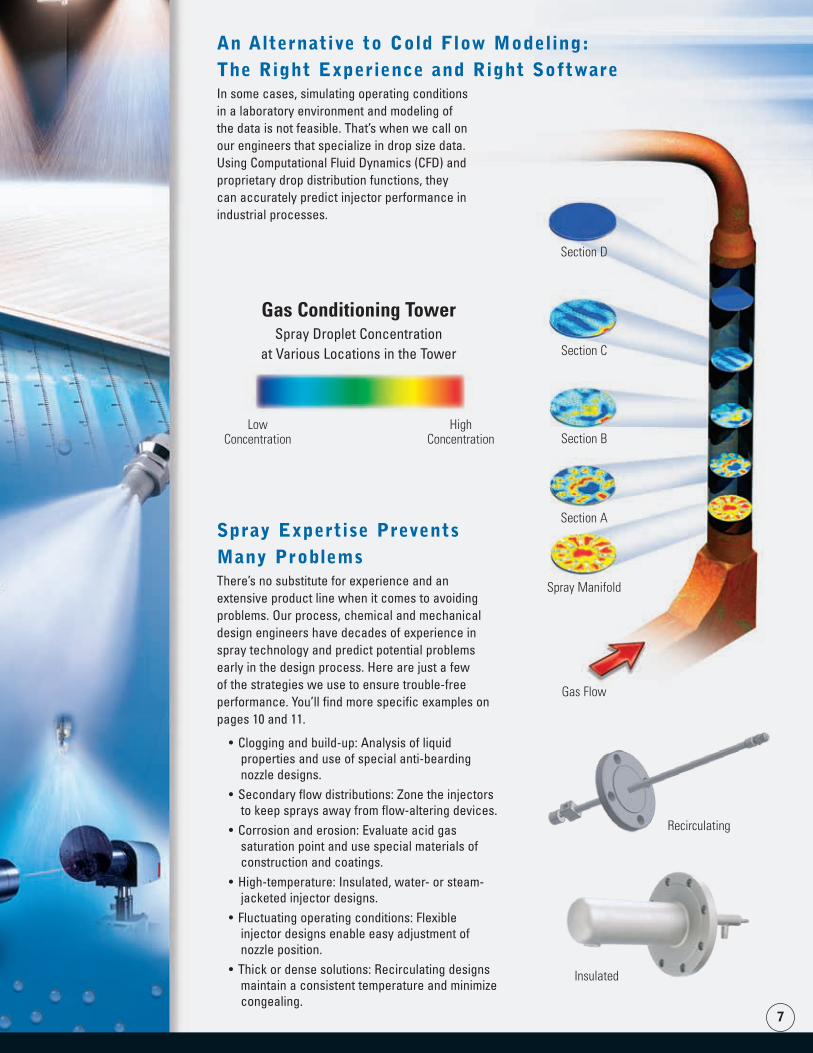
LowConcentration
HighConcentration
Spray Manifold
Section A
Section B
Section C
Section D
Gas Flow
�
An Alternative to Cold Flow Modeling: The Right Experience and Right SoftwareIn some cases, simulating operating conditions in a laboratory environment and modeling of the data is not feasible. That’s when we call on our engineers that specialize in drop size data. Using Computational Fluid Dynamics (CFD) and proprietary drop distribution functions, they can accurately predict injector performance in industrial processes.
Spray Expertise Prevents Many ProblemsThere’s no substitute for experience and an extensive product line when it comes to avoiding problems. Our process, chemical and mechanical design engineers have decades of experience in spray technology and predict potential problems early in the design process. Here are just a few of the strategies we use to ensure trouble-free performance. You’ll find more specific examples on pages 10 and 11.
• Clogging and build-up: Analysis of liquid properties and use of special anti-bearding nozzle designs.
• Secondary flow distributions: Zone the injectors to keep sprays away from flow-altering devices.
• Corrosion and erosion: Evaluate acid gas saturation point and use special materials of construction and coatings.
• High-temperature: Insulated, water- or steam-jacketed injector designs.
• Fluctuating operating conditions: Flexible injector designs enable easy adjustment of nozzle position.
• Thick or dense solutions: Recirculating designs maintain a consistent temperature and minimize congealing.
Recirculating
Insulated
Gas Conditioning TowerSpray Droplet Concentration
at Various Locations in the Tower

A single source solution for nozzles and custom injectors:
�
Choosing the right spray injector vendor can be the dif-ference between optimal spray performance and costly process inefficiencies/excessive maintenance downtime. Some companies call on internal design and fabrication resources for spray injectors. Other companies focus on cost and turn to small local fabricators. These providers do not have the required expertise in spray technology or a proven track record in injector design. There is a con-siderable risk of performance-related problems and spray nozzle integration issues when relying on one of these types of providers.
By choosing a partner with significant experience in spray nozzle and injector design, the likelihood of optimal spray performance increases significantly. And, if a single company supplies the nozzle and the lance, integration issues are eliminated while you enjoy the convenience of working with a single vendor.
Other considerations in the vendor selection process include:
• In-house design and engineering resources.• ASME® code compliance and manufacturing capacity. • Spray performance testing.• Materials testing.• Comprehensive documentation.• Efficient project management.
How to Select the
Right Vendor/Partner
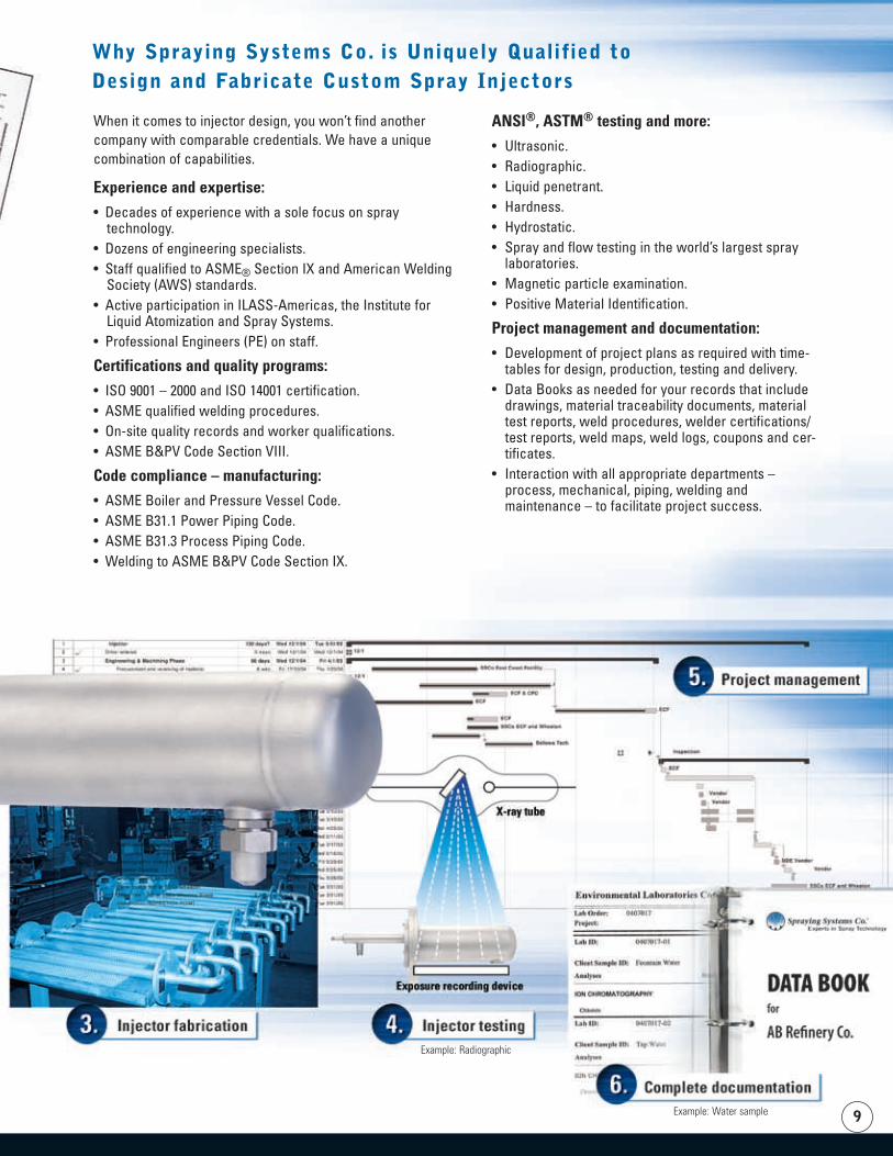
Example: Radiographic
Example: Water sample �
Why Spraying Systems Co. is Uniquely Qualified to Design and Fabricate Custom Spray Injectors
When it comes to injector design, you won’t find another company with comparable credentials. We have a unique combination of capabilities.
Experience and expertise:
• Decades of experience with a sole focus on spray technology.
• Dozens of engineering specialists.• Staff qualified to ASME® Section IX and American Welding
Society (AWS) standards.• Active participation in ILASS-Americas, the Institute for
Liquid Atomization and Spray Systems. • Professional Engineers (PE) on staff.
Certifications and quality programs:
• ISO 9001 – 2000 and ISO 14001 certification.• ASME qualified welding procedures.• On-site quality records and worker qualifications.• ASME B&PV Code Section VIII.
Code compliance – manufacturing:
• ASME Boiler and Pressure Vessel Code.• ASME B31.1 Power Piping Code.• ASME B31.3 Process Piping Code.• Welding to ASME B&PV Code Section IX.
ANSI®, ASTM® testing and more:
• Ultrasonic.• Radiographic.• Liquid penetrant.• Hardness.• Hydrostatic.• Spray and flow testing in the world’s largest spray
laboratories.• Magnetic particle examination.• Positive Material Identification.
Project management and documentation:
• Development of project plans as required with time-tables for design, production, testing and delivery.
• Data Books as needed for your records that include drawings, material traceability documents, material test reports, weld procedures, welder certifications/test reports, weld maps, weld logs, coupons and cer-tificates.
• Interaction with all appropriate departments – process, mechanical, piping, welding and maintenance – to facilitate project success.
10
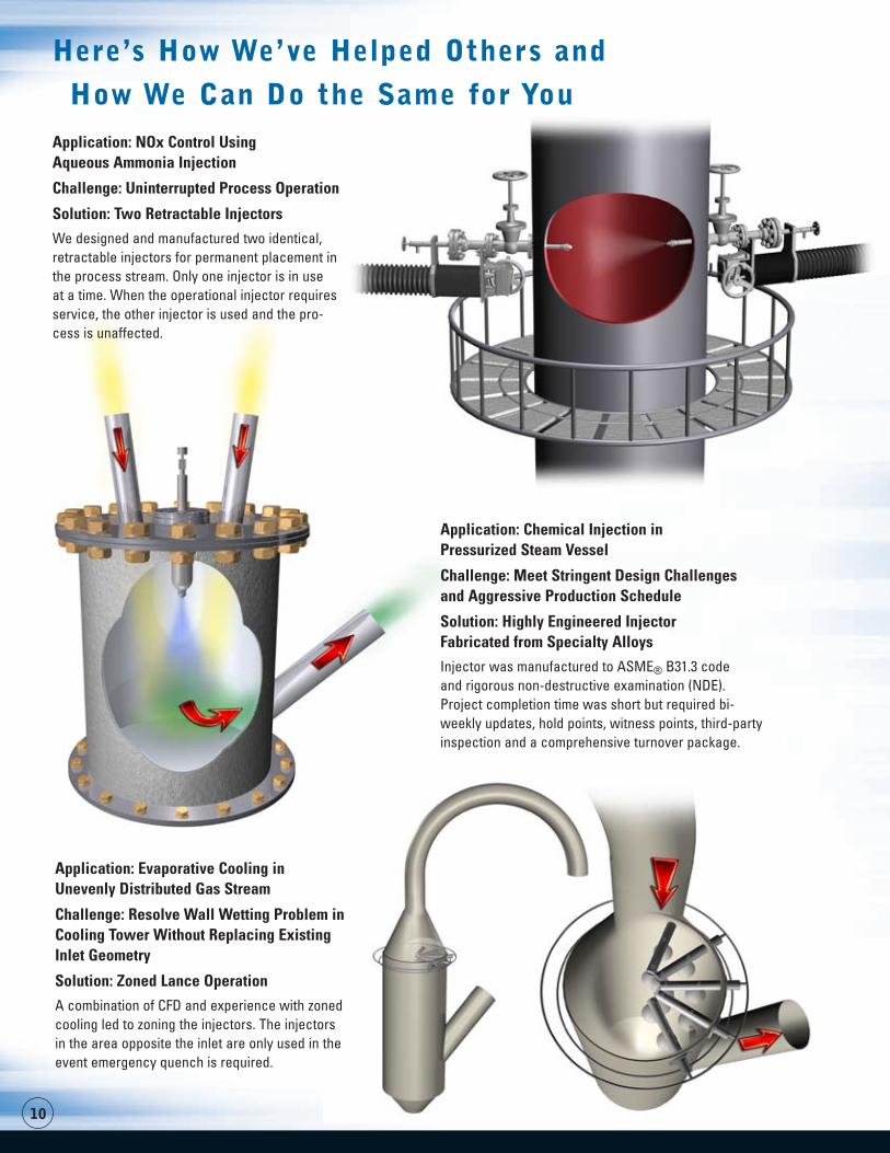
Here’s How We’ve Helped Others and
How We Can Do the Same for YouApplication: NOx Control Using Aqueous Ammonia Injection
Challenge: Uninterrupted Process Operation
Solution: Two Retractable Injectors
We designed and manufactured two identical, retractable injectors for permanent placement in the process stream. Only one injector is in use at a time. When the operational injector requires service, the other injector is used and the pro-cess is unaffected.
Application: Chemical Injection in Pressurized Steam Vessel
Challenge: Meet Stringent Design Challenges and Aggressive Production Schedule
Solution: Highly Engineered Injector Fabricated from Specialty Alloys
Injector was manufactured to ASME® B31.3 code and rigorous non-destructive examination (NDE). Project completion time was short but required bi-weekly updates, hold points, witness points, third-party inspection and a comprehensive turnover package.
Application: Evaporative Cooling in Unevenly Distributed Gas Stream
Challenge: Resolve Wall Wetting Problem in Cooling Tower Without Replacing Existing Inlet Geometry
Solution: Zoned Lance Operation
A combination of CFD and experience with zoned cooling led to zoning the injectors. The injectors in the area opposite the inlet are only used in the event emergency quench is required.
11
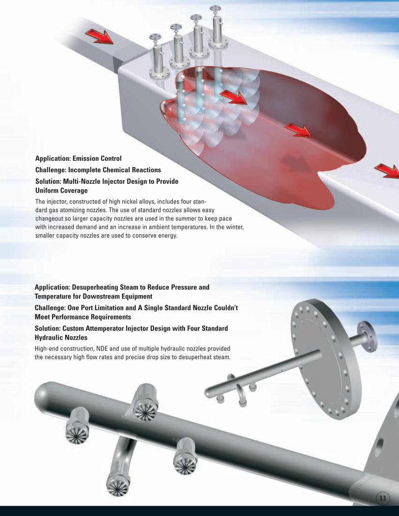
Application: Desuperheating Steam to Reduce Pressure and Temperature for Downstream Equipment
Challenge: One Port Limitation and A Single Standard Nozzle Couldn’t Meet Performance Requirements
Solution: Custom Attemperator Injector Design with Four Standard Hydraulic Nozzles
High-end construction, NDE and use of multiple hydraulic nozzles provided the necessary high flow rates and precise drop size to desuperheat steam.
Application: Emission Control
Challenge: Incomplete Chemical Reactions
Solution: Multi-Nozzle Injector Design to Provide Uniform Coverage
The injector, constructed of high nickel alloys, includes four stan-dard gas atomizing nozzles. The use of standard nozzles allows easy changeout so larger capacity nozzles are used in the summer to keep pace with increased demand and an increase in ambient temperatures. In the winter, smaller capacity nozzles are used to conserve energy.
ASME® is a registered trademark of American Society of Mechanical Engineers (ASME, ASME International).ANSI® is a registered trademark of the American National Standards Institute.ASTM® is a registered trademark of ASTM International.
Experts in Spray TechnologySpray
NozzlesSpray
ControlSpray
AnalysisSpray
Fabrication
Bulletin No. 579A Printed in the U.S.A. ©Spraying Systems Co. 2006
P.O. Box 7900, Wheaton, IL 60189-7900 USA
Tel: 1.800.95.SPRAY Intl. Tel: 1.630.665.5000 Fax: 1.888.95.SPRAY Intl. Fax: 1.630.260.0842www.spray.com
Additional Resources
We hope the information provided in this guide was helpful. If you are interested in learning more about spray nozzles and spray injectors, the following publications are available.
Spray Technology Reference Guide: Understanding Drop Size, Bulletin 459B
36-page guide delves into drop size measurement, instrumentation and data analysis/interpretation.
Optimizing Your Spray System, Technical Manual 410
52-page handbook explains how to evaluate your spray system, uncover and solve costly problems, improve quality, reduce maintenance time and more.
Gas Cooling and Conditioning Guide, Bulletin 540
12-page bulletin describes how to optimize efficiency and performance in gas cooling and conditioning applications.
FloMax® Air Atomizing Nozzles, Bulletin 487C
8-page bulletin explains how these high-efficiency nozzles work to provide precise spray performance through tight control of drop size.
Improving Process and Product Quality in Chemical Production through Spray Technology, Bulletin 568
12-page bulletin provides an overview of how spray technology is used in a wide range of applications.
Industrial Spray Products, Catalog 70
400-page catalog provides detailed information on our full line of spray products and accessories.
Bulletin 459B
Bulletin 540
Bulletin 487C
Catalog 70