a+ guide to managing & maintaining your pc, 8th edition · pdf filea+ guide to managing...
TRANSCRIPT
A+ Guide to Managing & Maintaining Your PC, 8th Edition
Chapter 6Supporting Hard Drives

© Cengage Learning 2014A+ Guide to Managing & Maintaining Your PC, 8th Edition
2
Objectives
• Learn about the technologies used inside a hard drive and how a computer communicates with a hard drive
• Learn how to select and install a hard drive
© Cengage Learning 2014A+ Guide to Managing & Maintaining Your PC, 8th Edition
3
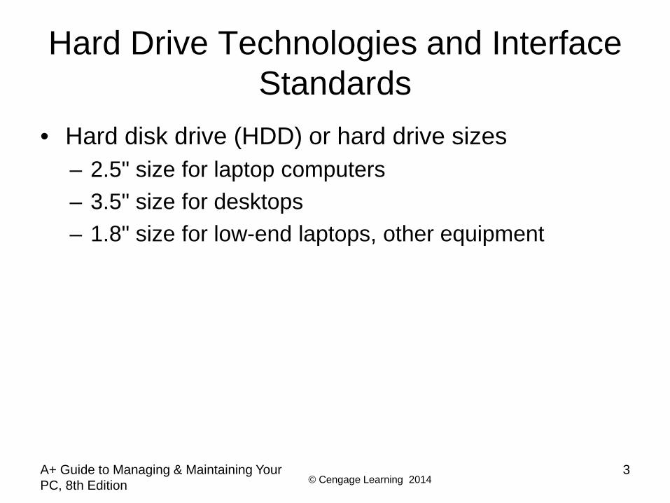
Hard Drive Technologies and Interface Standards
• Hard disk drive (HDD) or hard drive sizes– 2.5" size for laptop computers– 3.5" size for desktops– 1.8" size for low-end laptops, other equipment

© Cengage Learning 2014A+ Guide to Managing & Maintaining Your PC, 8th Edition
4
Technologies Used Inside a Hard Drive
• Solid state drive (SSD) or solid state device (SSD)– No moving parts– Built using nonvolatile flash memory stored on
EEPROM (Electronically Erasable Programmable Read Only Memory) chips
– Memory in an SSD is called NAND flash memory– Lifespan is based on the number of write operations
to the drive– Expensive technology, but faster, more reliable, last
longer, and use less power than magnetic drives
© Cengage Learning 2014A+ Guide to Managing & Maintaining Your PC, 8th Edition
5
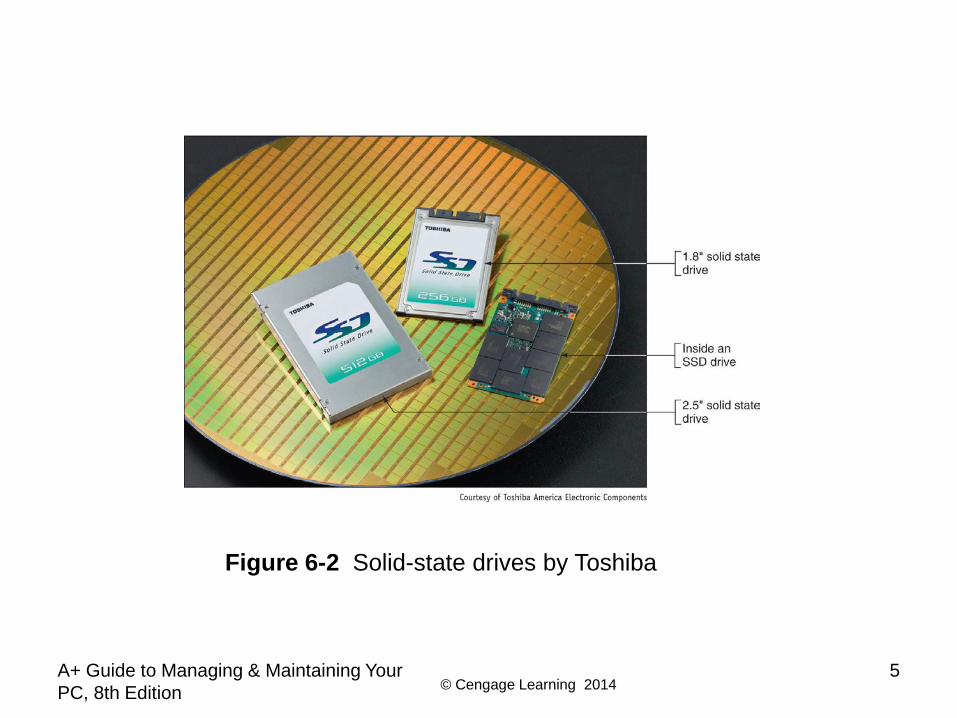
Figure 6-2 Solid-state drives by Toshiba

© Cengage Learning 2014A+ Guide to Managing & Maintaining Your PC, 8th Edition
6
© Cengage Learning 2014A+ Guide to Managing & Maintaining Your PC, 8th Edition
7
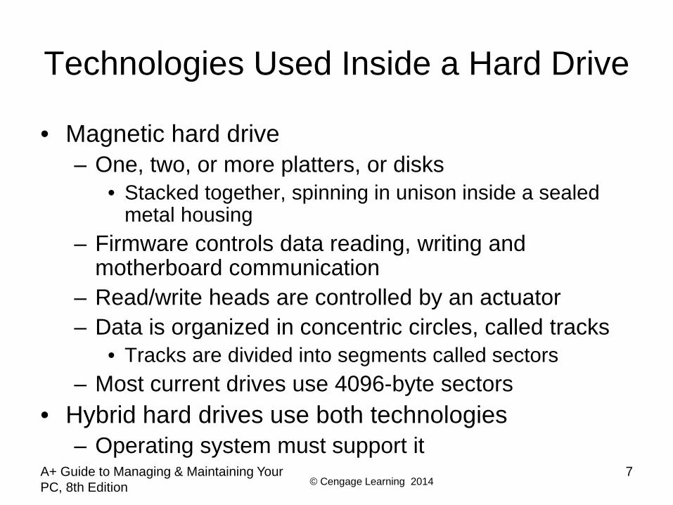
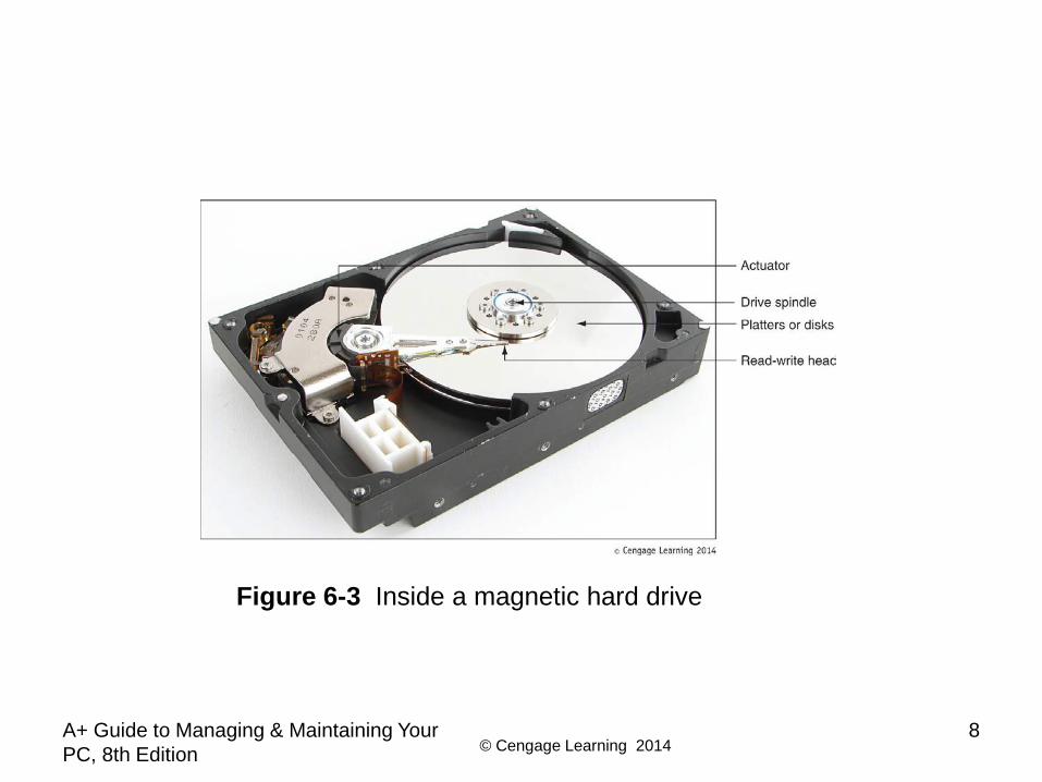
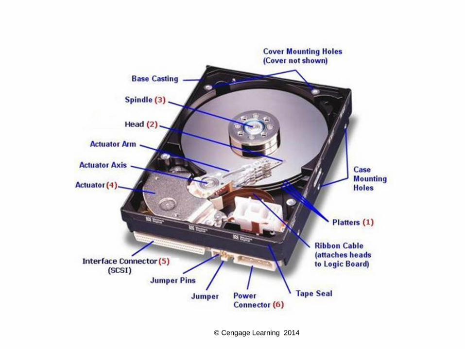
Technologies Used Inside a Hard Drive
• Magnetic hard drive– One, two, or more platters, or disks
• Stacked together, spinning in unison inside a sealed metal housing
– Firmware controls data reading, writing and motherboard communication
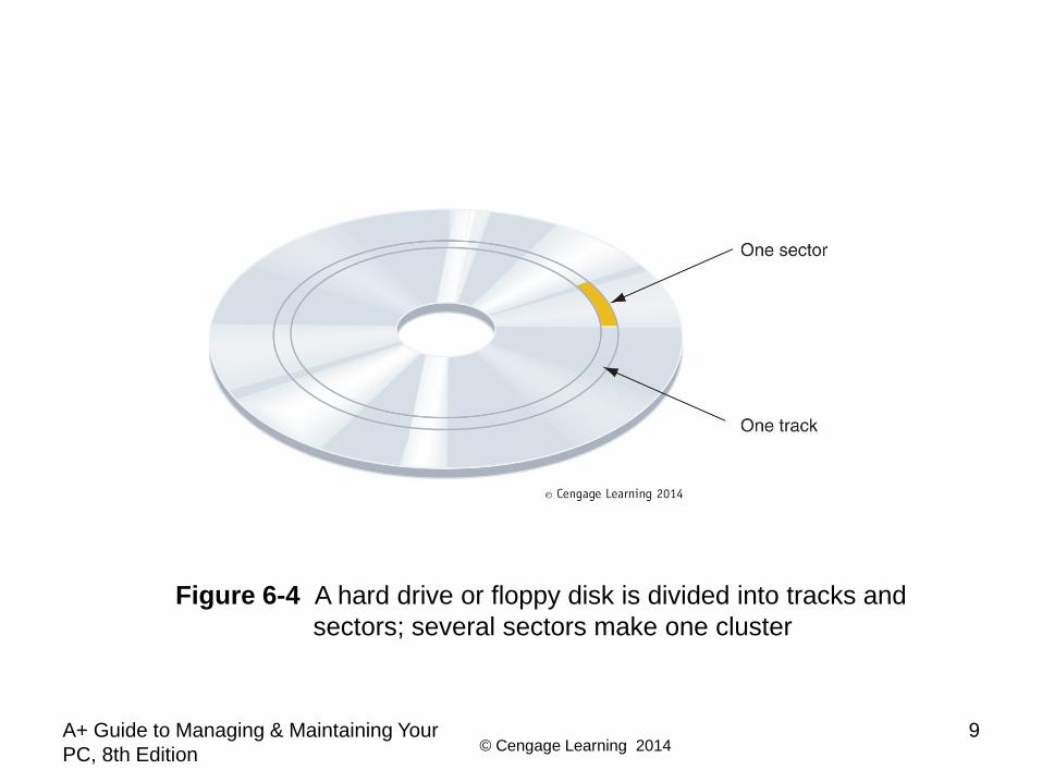
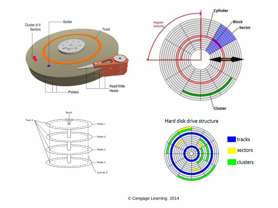
– Read/write heads are controlled by an actuator– Data is organized in concentric circles, called tracks
• Tracks are divided into segments called sectors– Most current drives use 4096-byte sectors
• Hybrid hard drives use both technologies– Operating system must support it
© Cengage Learning 2014A+ Guide to Managing & Maintaining Your PC, 8th Edition
8
Figure 6-3 Inside a magnetic hard drive
© Cengage Learning 2014A+ Guide to Managing & Maintaining Your PC, 8th Edition
9
Figure 6-4 A hard drive or floppy disk is divided into tracks and sectors; several sectors make one cluster
© Cengage Learning 2014
© Cengage Learning 2014
© Cengage Learning 2014
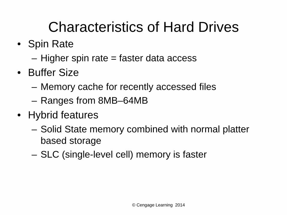
Characteristics of Hard Drives• Spin Rate
– Higher spin rate = faster data access• Buffer Size
– Memory cache for recently accessed files– Ranges from 8MB–64MB
• Hybrid features– Solid State memory combined with normal platter
based storage– SLC (single-level cell) memory is faster
© Cengage Learning 2014A+ Guide to Managing & Maintaining Your PC, 8th Edition
13
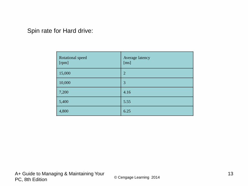
Rotational speed[rpm]
Average latency[ms]
15,000 2
10,000 3
7,200 4.16
5,400 5.55
4,800 6.25
Spin rate for Hard drive:
© Cengage Learning 2014A+ Guide to Managing & Maintaining Your PC, 8th Edition
14
Technologies Used Inside a Hard Drive
• Low-level formatting – sector markings are written to the hard drive at the factory – Not the same as high-level formatting performed for
Operating System installation• Firmware, BIOS and OS use logical block
addressing (LBA) to address all hard drive sectors– Size of each sector + total number of sectors
determine drive capacity• S.M.A.R.T – Self-Monitoring Analysis ad Reporting
Technology– Used to predict when a drive is likely to fail
© Cengage Learning 2014A+ Guide to Managing & Maintaining Your PC, 8th Edition
15
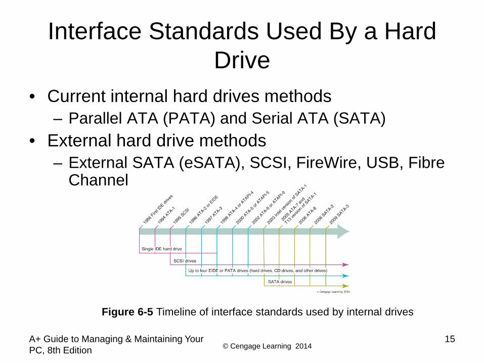
Interface Standards Used By a Hard Drive
• Current internal hard drives methods– Parallel ATA (PATA) and Serial ATA (SATA)
• External hard drive methods– External SATA (eSATA), SCSI, FireWire, USB, Fibre
Channel
Figure 6-5 Timeline of interface standards used by internal drives

© Cengage Learning 2014A+ Guide to Managing & Maintaining Your PC, 8th Edition
16
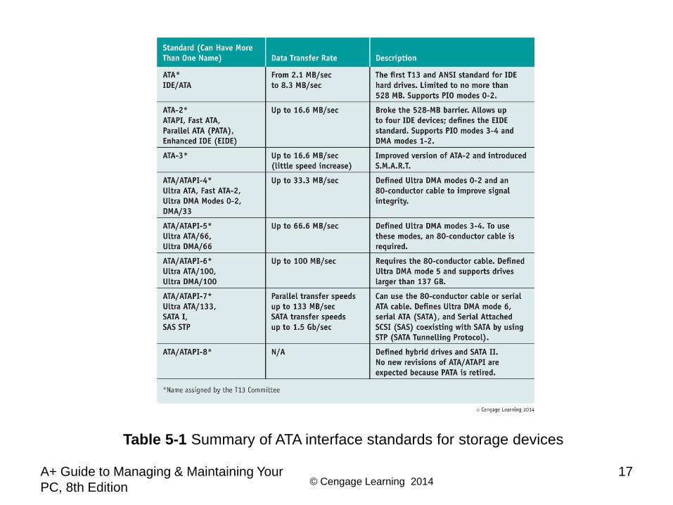
Interface Standards Used by a Hard Drive
• Interface standards define data speeds and transfer methods with a computer system– Also define types of cables and connectors
• Standards– Developed by Technical Committee T13– Published by American National Standards Institute
(ANSI)
© Cengage Learning 2014A+ Guide to Managing & Maintaining Your PC, 8th Edition
17
Table 5-1 Summary of ATA interface standards for storage devices

© Cengage Learning 2014A+ Guide to Managing & Maintaining Your PC, 8th Edition
18
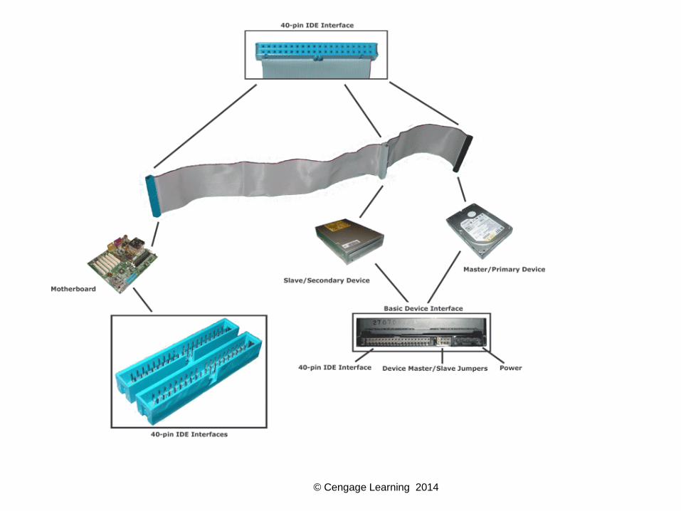
Parallel ATA or EIDE Drive Standards
• Parallel ATA or EIDE drive standards or Integrated Drive Electronics (IDE)– Allows one or two IDE connectors on a motherboard
• Each use 40-pin data cable– Advanced Technology Attachment Packet Interface
• Required by optical drives (e.g., CD or DVD)• Types of PATA ribbon cables
– Older cable • 40 pins and 40 wires
– 80-conductor IDE cable• 40 pins and 80 wires
– Maximum recommended length of either is 18”
© Cengage Learning 2014A+ Guide to Managing & Maintaining Your PC, 8th Edition
20
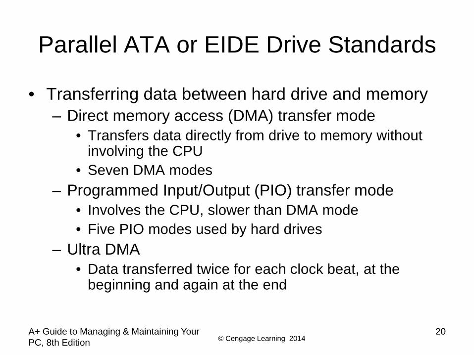
Parallel ATA or EIDE Drive Standards
• Transferring data between hard drive and memory– Direct memory access (DMA) transfer mode
• Transfers data directly from drive to memory without involving the CPU
• Seven DMA modes– Programmed Input/Output (PIO) transfer mode
• Involves the CPU, slower than DMA mode• Five PIO modes used by hard drives
– Ultra DMA• Data transferred twice for each clock beat, at the
beginning and again at the end

© Cengage Learning 2014A+ Guide to Managing & Maintaining Your PC, 8th Edition
21
Parallel ATA or EIDE Drive Standards
• Startup BIOS – Autodetects drive and selects fastest mode that drive
and BIOS support• Independent Device Timing
– Motherboard chipset feature– Supported by most chipsets today– Allows two hard drives to share same parallel ATA
cable but use different standards– Allows two drives to run at different speeds as long as
motherboard supports them
© Cengage Learning 2014A+ Guide to Managing & Maintaining Your PC, 8th Edition
22
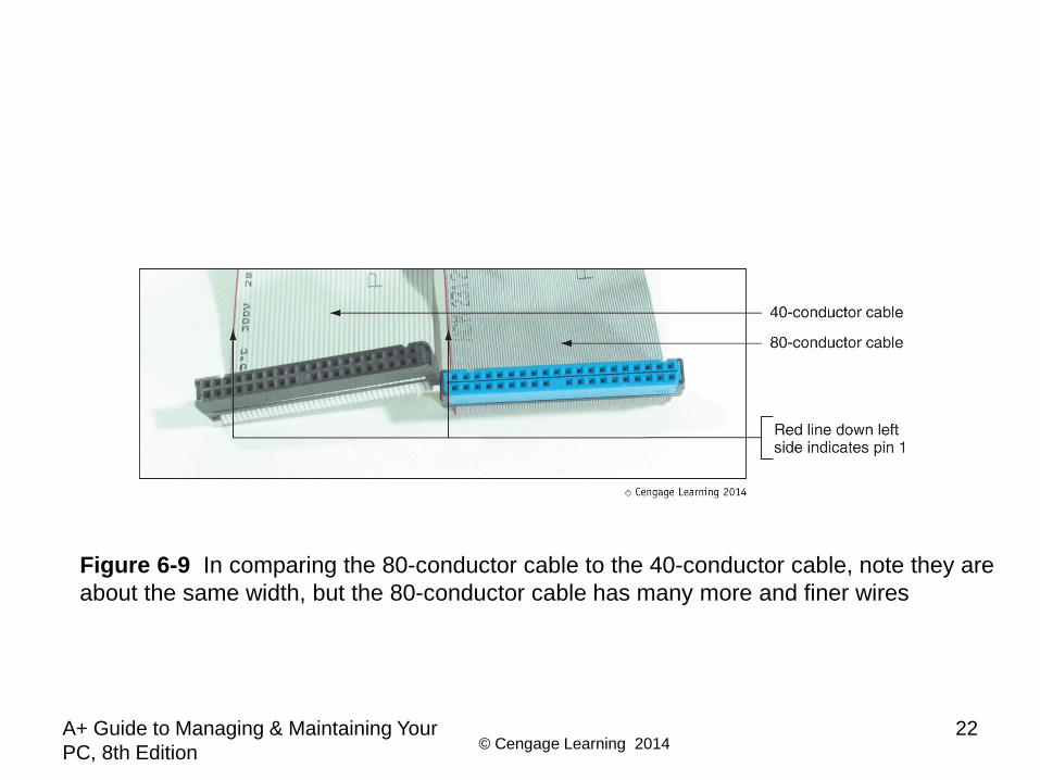
Figure 6-9 In comparing the 80-conductor cable to the 40-conductor cable, note they are about the same width, but the 80-conductor cable has many more and finer wires
© Cengage Learning 2014A+ Guide to Managing & Maintaining Your PC, 8th Edition
23
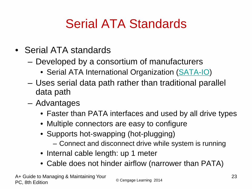
Serial ATA Standards
• Serial ATA standards– Developed by a consortium of manufacturers
• Serial ATA International Organization (SATA-IO)– Uses serial data path rather than traditional parallel
data path– Advantages
• Faster than PATA interfaces and used by all drive types• Multiple connectors are easy to configure• Supports hot-swapping (hot-plugging)
– Connect and disconnect drive while system is running• Internal cable length: up 1 meter• Cable does not hinder airflow (narrower than PATA)
© Cengage Learning 2014A+ Guide to Managing & Maintaining Your PC, 8th Edition
24
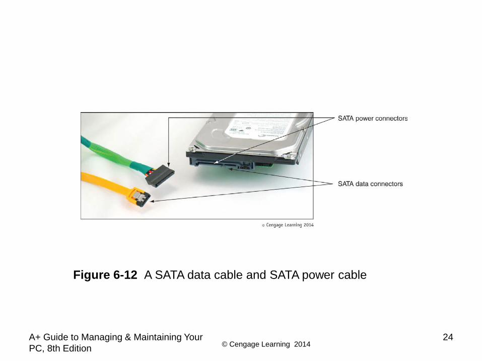
Figure 6-12 A SATA data cable and SATA power cable
© Cengage Learning 2014A+ Guide to Managing & Maintaining Your PC, 8th Edition
25
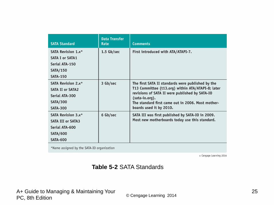
Table 5-2 SATA Standards
© Cengage Learning 2014A+ Guide to Managing & Maintaining Your PC, 8th Edition
26
Serial ATA Standards
• Serial ATA standards (cont’d.)– Motherboard or expansion card can provide external
SATA (eSATA) ports for external drives– External SATA (eSATA)
• eSATA drives use special external shielded serial ATA cable up to 2 meters long
– Purchasing considerations• SATA standards for the drive and motherboard need to
match for optimum speed• If no match, system runs at the slower speed
© Cengage Learning 2014
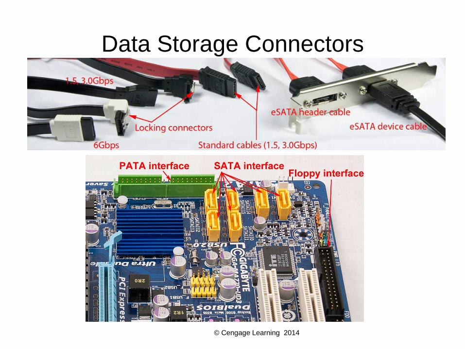
Data Storage Connectors

© Cengage Learning 2014
Hard Disk Power and Data Cables

© Cengage Learning 2014A+ Guide to Managing & Maintaining Your PC, 8th Edition
29
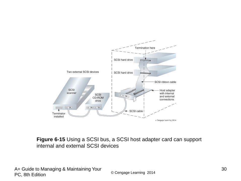
SCSI Technology• Small Computer System Interface standards
– Used primarily in servers– Support either 7 or 15 devices (standard dependent) – Provides better performance than ATA standards
• SCSI subsystem– SCSI controller types: embedded or host adapter– Host adapter supports internal and external devices– Daisy chain: combination of host adapter and devices– Each device on bus assigned SCSI ID (0 - 15)– A physical device can embed multiple logical devices
• Assigned a Logical Unit Number (LUN)
© Cengage Learning 2014A+ Guide to Managing & Maintaining Your PC, 8th Edition
30
Figure 6-15 Using a SCSI bus, a SCSI host adapter card can support internal and external SCSI devices
© Cengage Learning 2014A+ Guide to Managing & Maintaining Your PC, 8th Edition
31
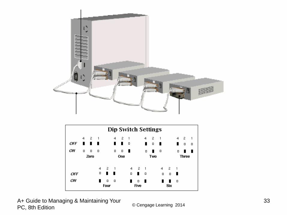
SCSI Technology
• Terminating resistor– Plugged into last device at end of the chain– Reduces electrical noise or interference on the cable
• Categories of SCSI Standards– 8-bit (narrow SCSI)
• Uses 50-pin SCSI connector (A cable) or 25-pin SCSI connector that looks like a parallel port (DB-25)
– 16-bit (wide SCSI)• Uses 68-pin SCSI connector (P cable)
© Cengage Learning 2014A+ Guide to Managing & Maintaining Your PC, 8th Edition
32
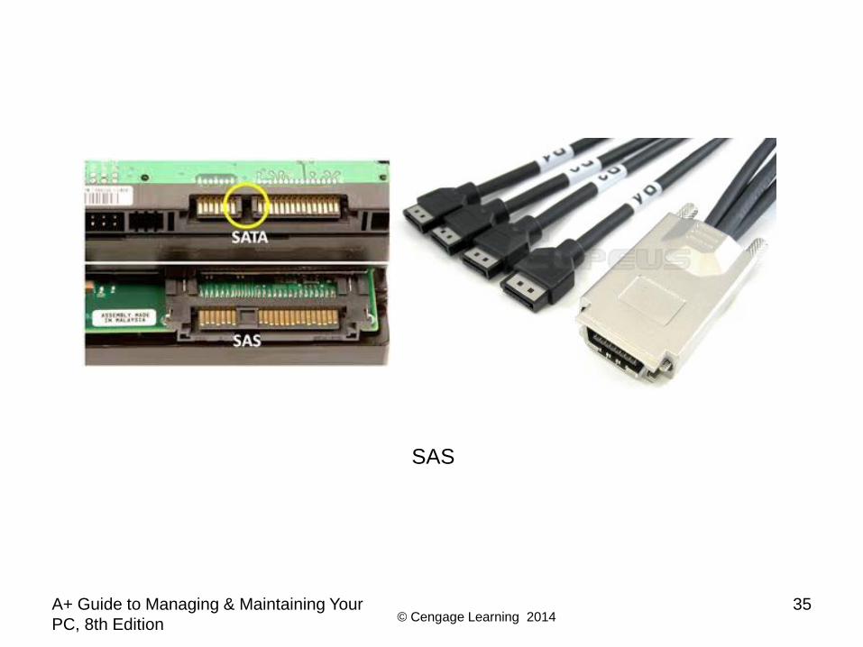
SCSI Technology
• Various SCSI versions– SCSI-1, SCSI-2, and SCSI-3
• Also known as regular SCSI, Fast SCSI, Ultra SCSI• Serial attached SCSI (SAS)
– Allows for more than 15 devices on single chain– Uses smaller, longer, round cables– Uses smaller hard drive form factors, larger capacities– Compatible with serial ATA
© Cengage Learning 2014A+ Guide to Managing & Maintaining Your PC, 8th Edition
33

© Cengage Learning 2014A+ Guide to Managing & Maintaining Your PC, 8th Edition
34
Figure 6-18 The most popular SCSI connectors are 50-pin, A-cable connectorsFor narrow SCSI and 68-pin, P-cable connectors for wide SCSI
SCSI Terminator
© Cengage Learning 2014A+ Guide to Managing & Maintaining Your PC, 8th Edition
35
SAS
© Cengage Learning 2014A+ Guide to Managing & Maintaining Your PC, 8th Edition
36
How to Select and Install Hard Drives
• Topics covered– Selecting a hard drive– Installation details for SATA drive, IDE drive– How to install hard drive in a bay too wide for drive– How to set up a RAID system
© Cengage Learning 2014A+ Guide to Managing & Maintaining Your PC, 8th Edition
37
Selecting a Hard Drive
• Hard drive must match OS and motherboard– Need to know what standards the motherboard or
controller card providing the drive interface can use– Consult documentation for the board or card
• BIOS uses autodetection to prepare the device – Drive capacity and configuration selected– Best possible ATA standard becomes part of
configuration
© Cengage Learning 2014A+ Guide to Managing & Maintaining Your PC, 8th Edition
38
Selecting a Hard Drive
• Considerations:– Drive capacity
• Today’s desktop hard drives range from 60 GB – 2 TB– Spindle speed
• Most common is 7200 RPM• The higher the RPMs, the faster the drive
– Interface standard• Use standards the motherboard supports
– Cache or buffer size• Ranges from 2 MB to 64 MB
© Cengage Learning 2014
Steps to Install a Serial ATA Drive
• Some SATA drives have two power connectors– Choose only one to use– Never install two power cords at the same time
• If you have a SATA drive and a PATA connector (or vice versa)– Purchase an adapter to make the drive fit the
motherboard connection– Can also purchase a SATA and/or PATA controller
card
A+ Guide to Managing & Maintaining Your PC, 8th Edition
39
© Cengage Learning 2014
Steps to Install a Serial ATA Drive
• Step 1: Know your starting point– How is your system configured?– Is everything working properly?– Write down what you know about the system
• Step 2: Read the documentation and prepare your work area– Read all installation instructions first– Visualize all the steps– Protect against ESD and avoid working on carpet
A+ Guide to Managing & Maintaining Your PC, 8th Edition
40
© Cengage Learning 2014
Steps to Install a Serial ATA Drive
• Step 2: Read the documentation and prepare your work area (cont’d)– Handle the drive carefully– Do not touch any exposed circuitry– Drain static electricity from the package and from your
body by touching metal for at least 2 seconds– Do not place the drive on the computer case or on a
metal table
A+ Guide to Managing & Maintaining Your PC, 8th Edition
41
© Cengage Learning 2014A+ Guide to Managing & Maintaining Your PC, 8th Edition
42
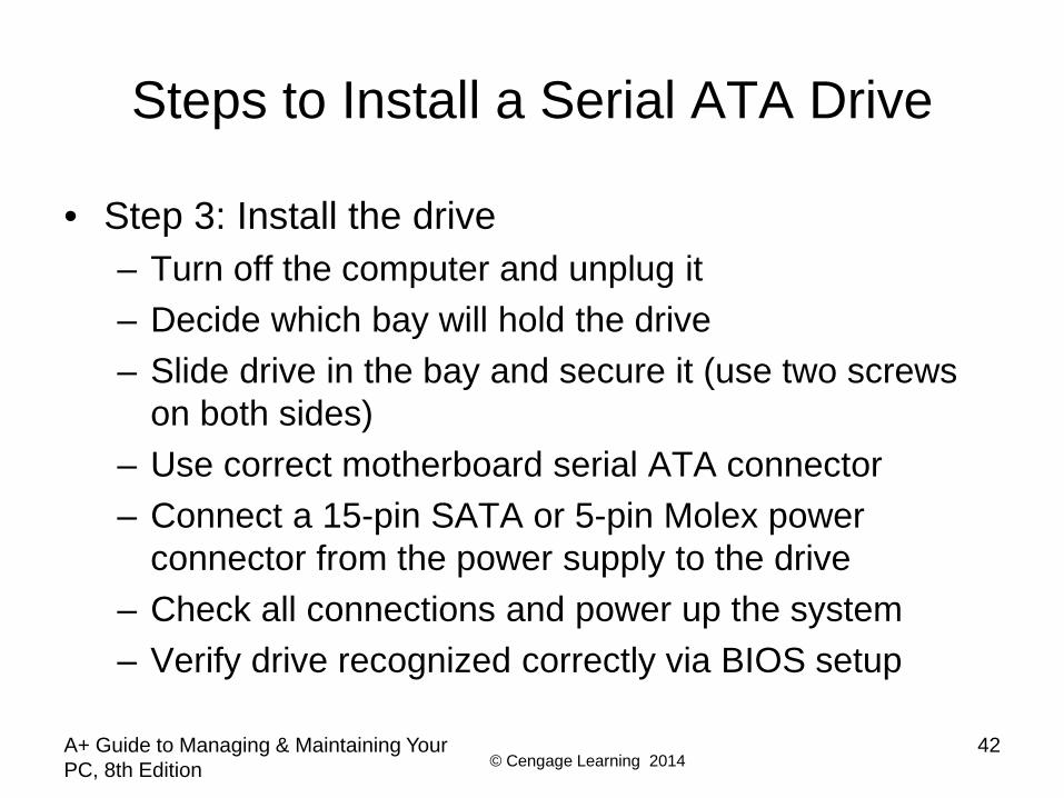
Steps to Install a Serial ATA Drive
• Step 3: Install the drive– Turn off the computer and unplug it– Decide which bay will hold the drive– Slide drive in the bay and secure it (use two screws
on both sides)– Use correct motherboard serial ATA connector– Connect a 15-pin SATA or 5-pin Molex power
connector from the power supply to the drive– Check all connections and power up the system– Verify drive recognized correctly via BIOS setup
© Cengage Learning 2014A+ Guide to Managing & Maintaining Your PC, 8th Edition
43
Steps to Install a Serial ATA Drive
• Now ready to prepare the hard drive for first use– Boot from Windows setup CD or DVD
• Follow directions on the screen to install Windows on the new drive
– If installing a second hard drive with Windows installed on first drive use Windows Disk Management utility to partition and format the second drive

© Cengage Learning 2014A+ Guide to Managing & Maintaining Your PC, 8th Edition
44
Steps to Install a Serial ATA Drive
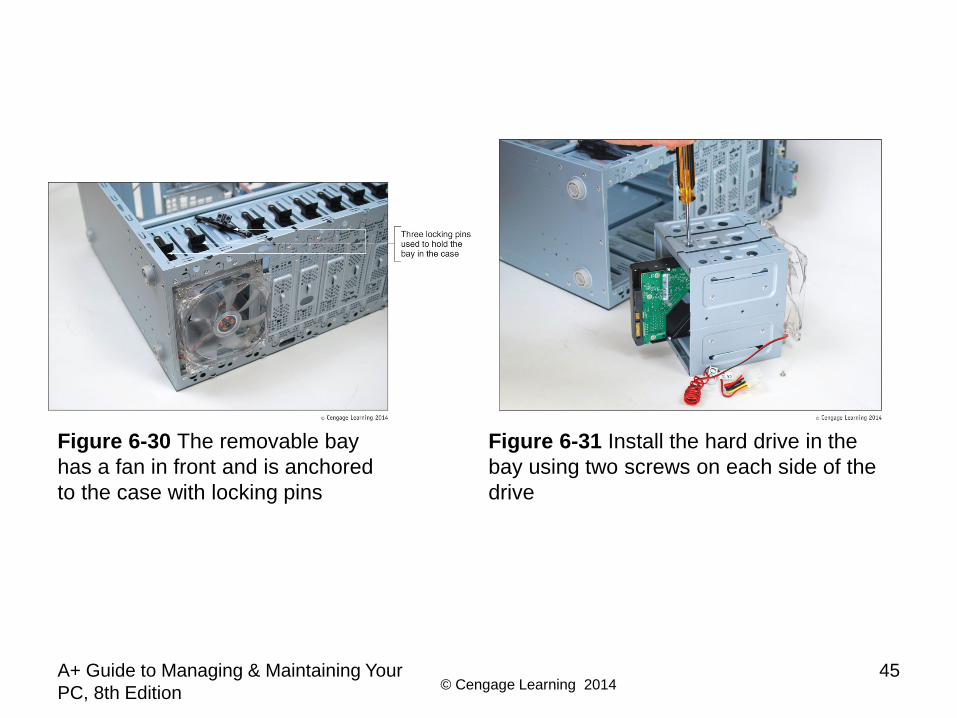
• Installing a drive in a removable bay– Unplug the cage fan from its power source– Turn handle on each locking device counterclockwise
to remove it– Slide the bay to the front and out of the case– Insert hard drive in the bay
• Use two screws on each side to anchor the drive in the bay
– Slide the bay back into the case– Reinstall the locking pins
© Cengage Learning 2014A+ Guide to Managing & Maintaining Your PC, 8th Edition
45
Figure 6-30 The removable bay has a fan in front and is anchored to the case with locking pins
Figure 6-31 Install the hard drive in the bay using two screws on each side of the drive
© Cengage Learning 2014A+ Guide to Managing & Maintaining Your PC, 8th Edition
46
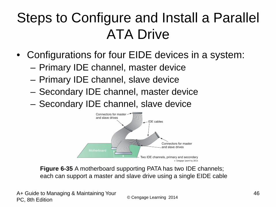
Steps to Configure and Install a Parallel ATA Drive
• Configurations for four EIDE devices in a system:– Primary IDE channel, master device– Primary IDE channel, slave device– Secondary IDE channel, master device– Secondary IDE channel, slave device
Figure 6-35 A motherboard supporting PATA has two IDE channels; each can support a master and slave drive using a single EIDE cable
© Cengage Learning 2014A+ Guide to Managing & Maintaining Your PC, 8th Edition
47
Steps to Configure and Install a Parallel ATA Drive
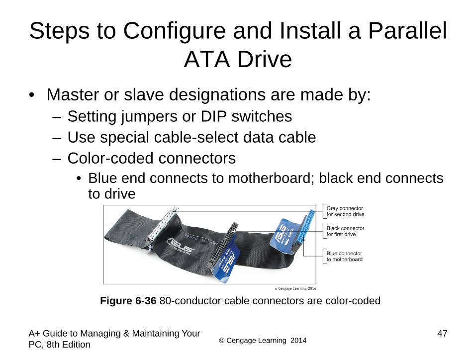
• Master or slave designations are made by:– Setting jumpers or DIP switches – Use special cable-select data cable– Color-coded connectors
• Blue end connects to motherboard; black end connects to drive
Figure 6-36 80-conductor cable connectors are color-coded
© Cengage Learning 2014A+ Guide to Managing & Maintaining Your PC, 8th Edition
48
Steps to Configure and Install a Parallel ATA Drive
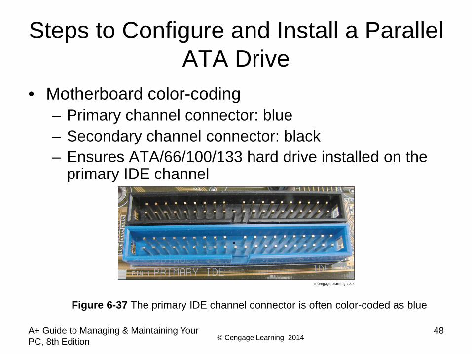
• Motherboard color-coding– Primary channel connector: blue– Secondary channel connector: black– Ensures ATA/66/100/133 hard drive installed on the
primary IDE channel
Figure 6-37 The primary IDE channel connector is often color-coded as blue
© Cengage Learning 2014A+ Guide to Managing & Maintaining Your PC, 8th Edition
49
Steps to Configure and Install a Parallel ATA Drive
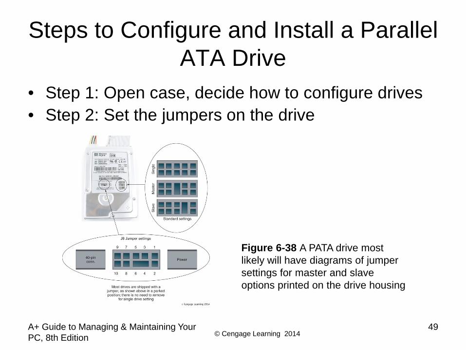
• Step 1: Open case, decide how to configure drives• Step 2: Set the jumpers on the drive
Figure 6-38 A PATA drive most likely will have diagrams of jumper settings for master and slave options printed on the drive housing
© Cengage Learning 2014A+ Guide to Managing & Maintaining Your PC, 8th Edition
50
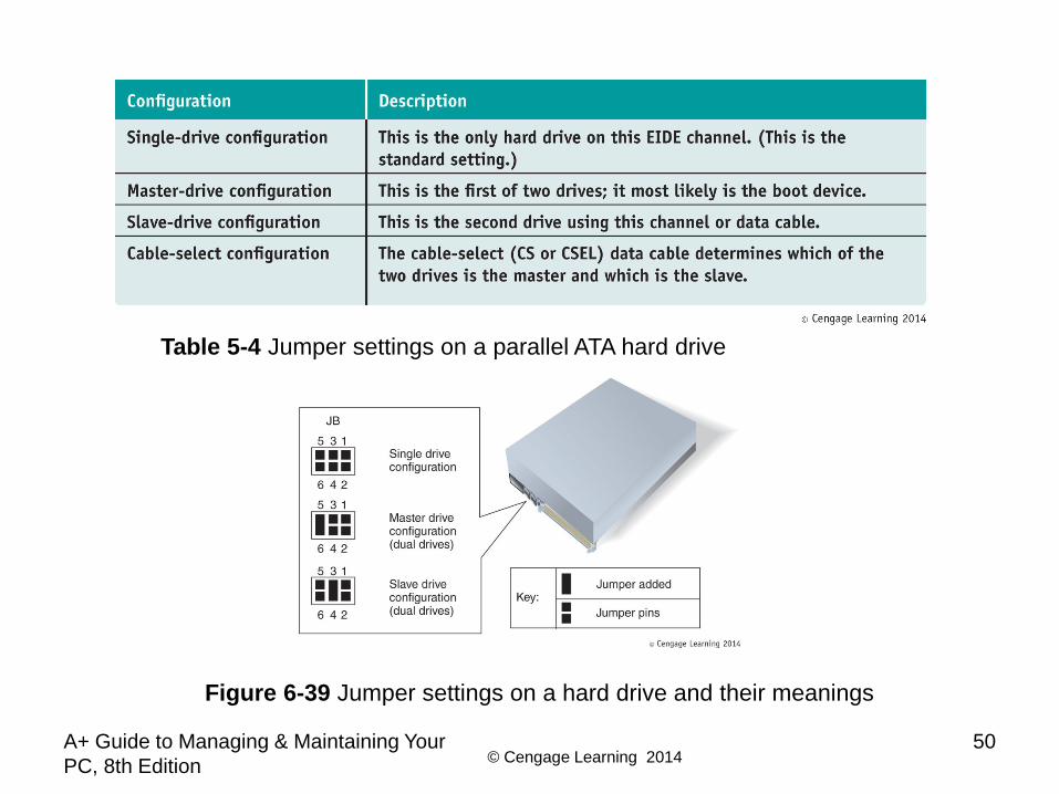
Table 5-4 Jumper settings on a parallel ATA hard drive
Figure 6-39 Jumper settings on a hard drive and their meanings

© Cengage Learning 2014A+ Guide to Managing & Maintaining Your PC, 8th Edition
51
Steps to Configure and Install a Parallel ATA Drive
• Step 3: Mount the drive in the bay– Decide whether to connect data cable before or after
inserting bay inside the computer case• Then install drive in bay and connect the cable in
whichever order works best– Connect data cable to IDE connector on motherboard– Install a power connection to each drive– Before replacing case cover verify installation
© Cengage Learning 2014
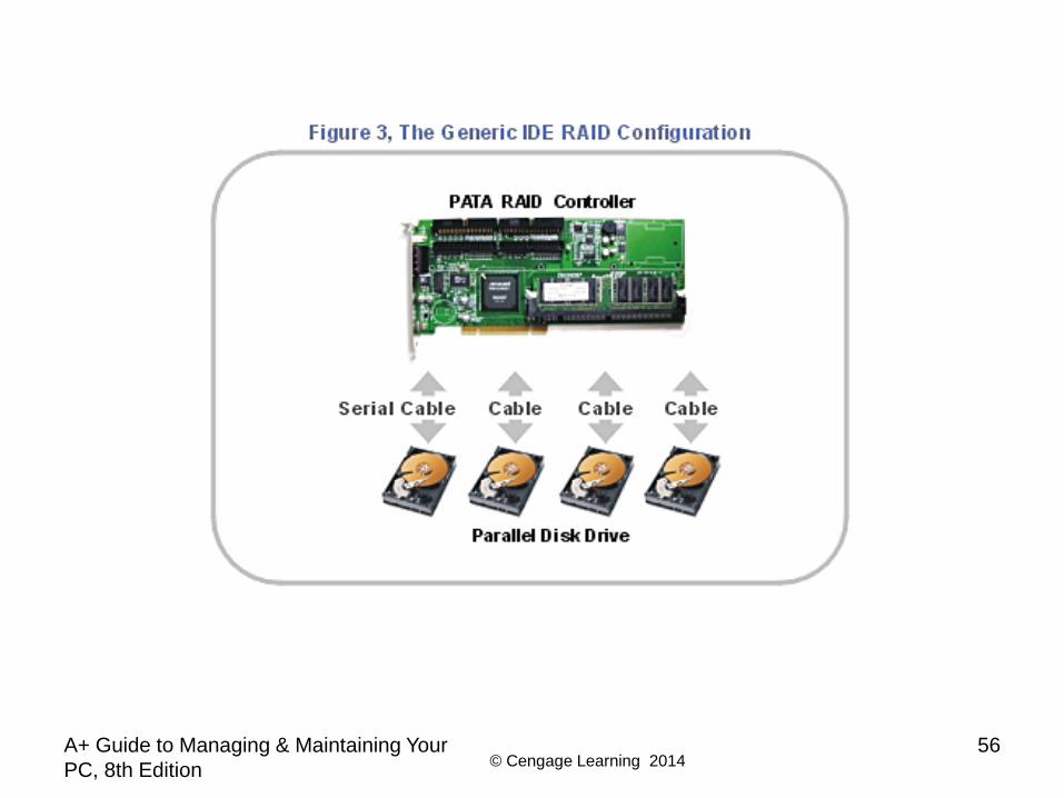
Setting Up Hardware RAID
• RAID (Redundant Array of Inexpensive Disks)– Also: Redundant Array of Independent Disks– A technology that configures two or more hard drives
to work together as an array of drives• Why use RAID?
– To improve fault tolerance by writing two copies of it, each to a different hard drive
– To improve performance by writing data to two or more hard drives to that a single drive is not excessively used
A+ Guide to Managing & Maintaining Your PC, 8th Edition
52
© Cengage Learning 2014
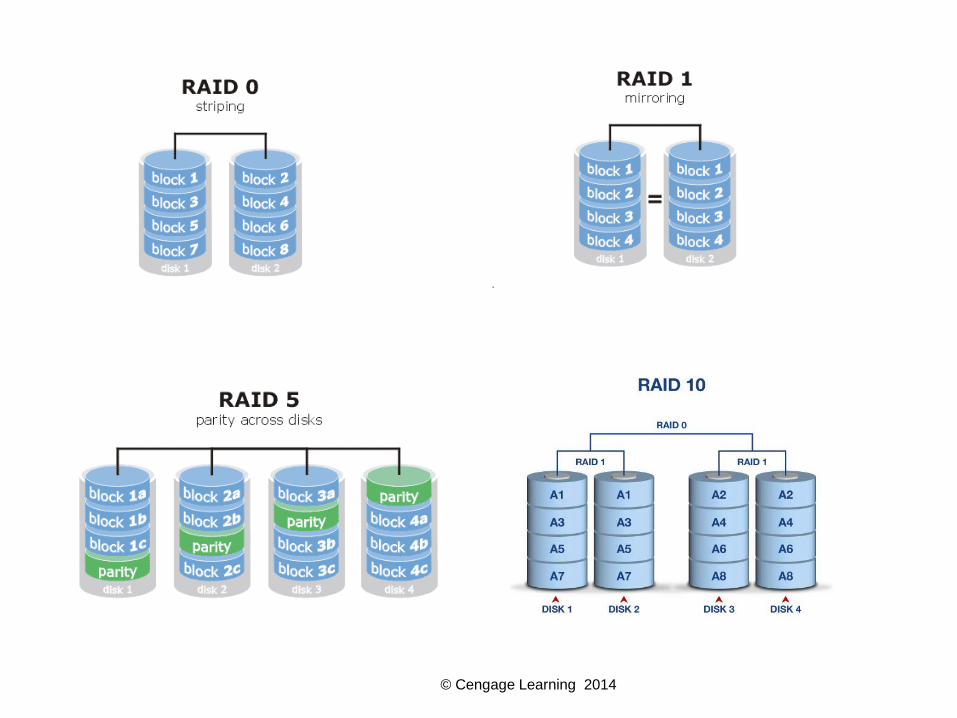
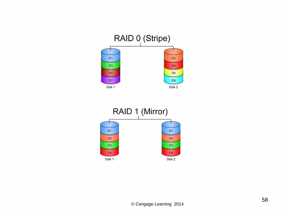
Types of RAID
• Spanning – sometimes called JBOD (just a bunch of disks)– Uses two hard drives to hold a single Windows
volume– When one drive is full, data is written to second drive
• RAID 0 – uses two or more physical disks– Writes to physical disks evenly across all disks so that
no one disk receives all activity– Windows calls RAID 0 a striped volume
A+ Guide to Managing & Maintaining Your PC, 8th Edition
53
© Cengage Learning 2014
Types of RAID
• RAID 1: Mirroring– Duplicates data on one drive to another drive and is
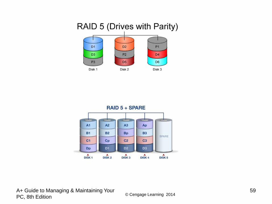
used for fault tolerance (mirrored volume)• RAID 5: uses three or more drives
– Stripes data across drives and uses parity checking– Data is not duplicated
• RAID 10: RAID 1+0 (pronounced RAID one zero) (Mirror and Stripe)– Combination of RAID 1 and RAID 0– Takes at least 4 disks
A+ Guide to Managing & Maintaining Your PC, 8th Edition
54
© Cengage Learning 2014
© Cengage Learning 2014A+ Guide to Managing & Maintaining Your PC, 8th Edition
56

© Cengage Learning 2014
RAID Configuration• Must have a motherboard that supports one of the RAID types.• When changing to a RAID system, existing data will likely be lost.
Back it up.• Sizing for RAID 5:
– For maximum benefit, all drives should be of similar size.• The smallest drive determines the capacity.• Capacity equals smallest drive x number of drives minus the
capacity of the smallest drive (for parity).– Parity is the math calculation performed on the drives
that allows a single drive to fail and still recover the data.– Example, RAID 5, 3 drives: 40GB, 60GB, 60GB drives:
» Storage capacity is (3 x 40) – 40 = 80 GB– A RAID drive is treated as a single drive after it is configured.
© Cengage Learning 201458
© Cengage Learning 2014A+ Guide to Managing & Maintaining Your PC, 8th Edition
59

© Cengage Learning 2014A+ Guide to Managing & Maintaining Your PC, 8th Edition
60

© Cengage Learning 2014A+ Guide to Managing & Maintaining Your PC, 8th Edition
61
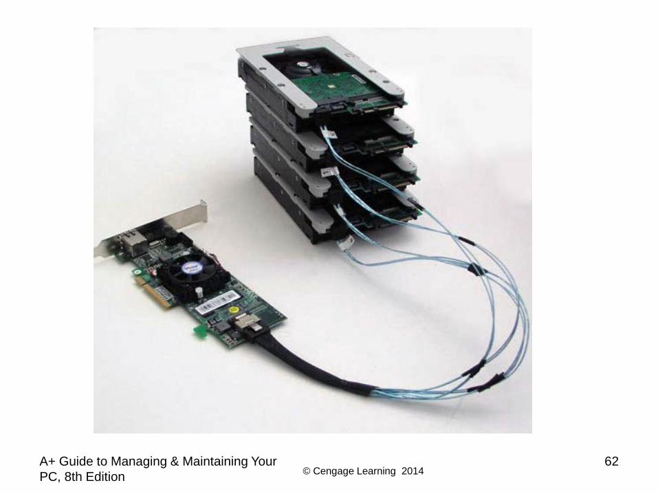
How to Implement Hardware RAID
• Hardware implementation– Hardware RAID controller or RAID controller card
• Motherboard does the work, Windows unaware of hardware RAID implementation
• Software implementation uses operating system• Best RAID performance
– All hard drives in an array should be identical in brand, size, speed, other features
• If Windows installed on a RAID hard drive RAID must be implemented before Windows installed
© Cengage Learning 2014A+ Guide to Managing & Maintaining Your PC, 8th Edition
62

© Cengage Learning 2014A+ Guide to Managing & Maintaining Your PC, 8th Edition
63
Figure 6-45 RAID controller card provides four SATA internal connectors
© Cengage Learning 2014A+ Guide to Managing & Maintaining Your PC, 8th Edition
64
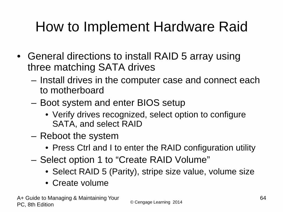
How to Implement Hardware Raid
• General directions to install RAID 5 array using three matching SATA drives– Install drives in the computer case and connect each
to motherboard– Boot system and enter BIOS setup
• Verify drives recognized, select option to configure SATA, and select RAID
– Reboot the system• Press Ctrl and I to enter the RAID configuration utility
– Select option 1 to “Create RAID Volume”• Select RAID 5 (Parity), stripe size value, volume size• Create volume
© Cengage Learning 2014A+ Guide to Managing & Maintaining Your PC, 8th Edition
65
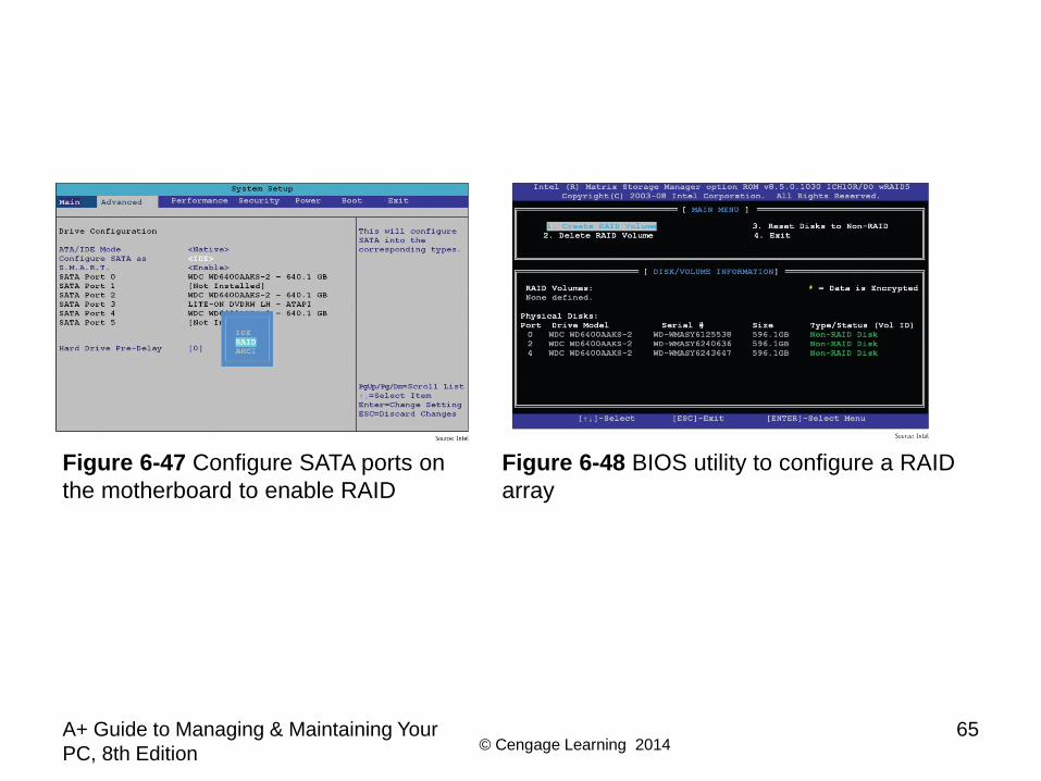
Figure 6-47 Configure SATA ports on the motherboard to enable RAID
Figure 6-48 BIOS utility to configure a RAID array

© Cengage Learning 2014A+ Guide to Managing & Maintaining Your PC, 8th Edition
66
Figure 6-49 Make your choices for the RAID array
© Cengage Learning 2014
About Tape Drives and Floppy Drives
• Tape drives can use a SATA, PATA, or SCSI interface
• As a technician, you may be called on to support old floppy drives
• Both tape drives and floppy drives are covered in this section
A+ Guide to Managing & Maintaining Your PC, 8th Edition
67

© Cengage Learning 2014
Installing Tape Drives and Selecting Tape Media
• Tapes drives – an inexpensive way of backing up a hard drive
• WORM (write once read many) – assures data written will not be deleted or overwritten
• Disadvantage: data is stored by sequential access – To read data from anywhere on the tape, you must
start at the beginning of the tape and read until you find the data you want
– Slow and inconvenient
A+ Guide to Managing & Maintaining Your PC, 8th Edition
68
© Cengage Learning 2014
Installing Tape Drives and Selecting Tape Media
• Two kinds of tapes:– Full-sized data cartridges– Minicartridges
• More popular because their drives can fit into a standard 3-inch drive bay of a PC case
• When selecting a tape drive, consider:– How many and what type of cartridges the drive can
use– How it interfaces with the computer
• External drives can connect to a computer using a USB, FireWire, SCSI, SAS, or eSATA port
A+ Guide to Managing & Maintaining Your PC, 8th Edition
69
© Cengage Learning 2014
Installing a Floppy Drive
• Floppy disk drive (FDD)– 3 ½” floppy disk format– Holds only 1.44 MB of data– Floppy drive subsystem
• Floppy drive, ribbon cable, power cable, connections• Today’s floppy drive cables have a connector at each
end to accommodate a single drive• Older cables have an extra connector or two in the
middle of the cable for a second floppy drive
A+ Guide to Managing & Maintaining Your PC, 8th Edition
70
© Cengage Learning 2014A+ Guide to Managing & Maintaining Your PC, 8th Edition
71
Installing a Floppy Drive
• Install the drive in a bay as you would a hard drive• Connect floppy drive data cable and power cord to
motherboard– If you connect the cable the wrong way, the drive light
will stay lit and will not work– Be sure the end of the cable with the twist connects to
the drive and the other end to the motherboard• Replace cover, turn on computer, and enter BIOS
setup to verify installation
© Cengage Learning 2014A+ Guide to Managing & Maintaining Your PC, 8th Edition
72
Summary
• A hard disk drive (HDD) comes in 3.5” for desktop and 2.5” for laptops
• A hard drive can be magnetic, solid-state, or hybrid• Most hard drives use the ATA interface standards• Two ATA categories are parallel ATA and serial ATA• S.M.A.R.T is a self-monitoring technology whereby
the BIOS monitors the health of a hard drive• SCSI interface standards include narrow and wide
SCSI and can use a variety of cables and connectors
© Cengage Learning 2014A+ Guide to Managing & Maintaining Your PC, 8th Edition
73
Summary
• When selecting a hard drive, consider storage capacity, technology, spindle speed, interface standard, and buffer size
• SATA drives require no configuration and are installed using a power cord and a data cable
• PATA drives require you to set a jumper to determine if the drive will be the single drive, master, or slave on a single cable
• RAID technology uses an array of hard drives to provide fault tolerance and/or improvement in performance

© Cengage Learning 2014
Summary
• Hardware RAID is implemented using the motherboard BIOS or a RAID controller card
• Software RAID is implemented in Windows• Tape drives are an inexpensive way to back up an
entire hard drive or portions of it• Today’s floppy disks are 3.5” high-density disks that
hold 1.44 MB of data• After a floppy disk drive is installed, you must
configure the drive in BIOS setup
A+ Guide to Managing & Maintaining Your PC, 8th Edition
74