a gestalt framework for virtual machine control of ...pygestalt.org/vmc_iem.pdf3 a gestalt framework...
TRANSCRIPT

A Gestalt Framework for Virtual Machine Control of Automated Tools
Ilan Ellison Moyer
S.B. Massachusetts Institute of Technology, 2008
Submitted to the Department of Mechanical Engineering in Partial Fulfillment of the Requirements for the Degree of
Master of Science
in Mechanical Engineering
at the
MASSACHUSETTS INSTITUTE OF TECHNOLOGY
September 2013
© 2013 Massachusetts Institute of Technology. All rights reserved.
Author………………………………………………………………………………..
Department of Mechanical Engineering August 9, 2013
Certified by…………………………………………………………………………...
David R. Wallace Professor of Mechanical Engineering
Thesis Supervisor
Accepted by………………………………………………………………………….. David E. Hardt
Chairman, Department Committee on Graduate Theses


3
A Gestalt Framework for Virtual Machine Control of Automated Tools
Ilan Ellison Moyer
Submitted to the Department of Mechanical Engineering
on August 9, 2013 in Partial Fulfillment of the Requirements for the Degree of Master of Science in Mechanical Engineering
Abstract
Computer aided design has become affordable and ubiquitous, in part as a result of the development of open source design software and web-based 3D modeling tools. Consequently, a broad spectrum of individuals are expressing demand for access to digital fabrication tools that are capable of automatically rendering their computer-based designs into physical objects. In response, manufacturers have begun to produce low-cost versions of a limited set of automated, personal-use fabrication tools, including 3D printers and desktop milling machines. Simultaneously, groups of individuals and organizations are establishing community workshops where resources can be pooled to acquire industrial-grade machinery. Both of these approaches have been successful at increasing the penetration of digital fabrication capabilities into the general population. However, there are many industrial tools which currently have no consumer-centric equivalent, and for which demand is insufficient to warrant acquisition by a community workshop. Additionally, as digital design continues to find new applications among a larger and more diverse audience, new needs will likely arise for yet non-existent automated fabrication tools. Gestalt is an accessible and flexible control framework which aims to augment the ability of individuals to create new automated tools, and to thus self-extend their abilities to create objects which would be too tedious or impossible to create by hand. This work will enable individuals to rapidly construct controllers and rich user interfaces for automated personal fabrication tools. The approach taken is that of a software-based virtual machine controlling a physical machine. This allows for increased modularity in controller implementation, and tighter integration of the tool with user applications than is possible with traditional controller architectures. The foundation of the proposed system provides a means for building APIs to communicate with modular hardware components, and a method of combining the functionality of these components at the virtual machine level (rather than in hardware) to yield higher-level functionality. The Python library developed in this work enables the rapid construction of cross-platform virtual machines that are capable of representing and controlling a wide variety of tools over commonly available interfaces such as USB. Additionally, a matching C library assists in developing microcontroller firmware for building custom modular hardware elements that can communicate with the virtual machine. A spectrum of unique fabrication tools controlled using the Gestalt framework are presented as case studies which elucidate both the successes and limitations of our approach. Thesis Supervisor: Professor David R. Wallace

5
Acknowledgements
I owe thanks to many individuals whose effort, ideas, and mentorship have been of help to the development of this thesis, and to my development as a person and as a designer. First and foremost I would like to thank my thesis advisor, Professor David Wallace, whose advice, mentorship, support, and willingness to give me freedom to explore, have played a pivotal role in shaping this work. Professor Wallace’s relentless drive to teach by example has successfully imprinted lessons that I will carry with me forever. Nadya Peek has been one of my close friends throughout my time in graduate school and my compatriot in several personal fabrication exploits. I thank her for friendship, philosophical discussions about fabrication, technical collaboration over the course of a number of projects, and very recently, her tireless help editing many revisions of this document. The work presented here first begun many years ago during my time as an undergraduate student in Professor Neil Gershenfeld’s lab. It is to him that I owe thanks for exposing me to the idea of a virtual machine controlling a physical machine from which the framework developed here has evolved. His support and encouragement since I joined his lab as a UROP student has been important directly to this thesis, and also played a strong role in prompting me to learn many of the skills upon which the implementation of the Gestalt framework depends. In the intervening time between my completion of undergraduate studies and the beginning of graduate school, I had the pleasure of working with and learning from many individuals as part of the Machines That Make project within the MIT Center for Bits and Atoms, including Maxim Lobovsky, Jonathan Ward, David Carr, Steve Liebman, Nadya Peek, Skylar Tibbits, Natan Linder, and others. In particular, Maxim Lobovsky, who was my collaborator for several years as a part of the MTM project, has shaped my philosophy towards digital fabrication tools. Steve Leibman helped to come up with one of the crucial ideas driving the architecture of Gestalt: that tools should be controlled directly by high level programming languages rather than the decades-old G-code standard. Ed Baafi first exposed me to the idea of browser-based control of computer-local devices with his Modkit implementation, and also suggested the idea of applying the technique to the control of machine tools. I would like to thank Robert Swartz for the many eye-opening philosophical discussions we have had about personal and digital fabrication over the past several years.

6
David Mellis has been inspirational in his approach towards understanding digital fabrication within the context of society. I would like to thank him, Nadya Peek, and the other participants of the Media Lab’s Digital Fabrication Working Group for numerous interesting discussions. Recently I have enjoyed working with two undergraduate students, Benjamin Niewood and Lauren Wright, who have helped with various aspects of this project. Specifically, Ben Niewood helped to build a significant portion of the mechanical hardware for the distributed control case study, and Lauren Wright assisted by debugging the Jacquard loom and getting its virtual machine to run on a Raspberry Pi. Many thanks to my friends Steve Keating, Geoff Tsai, and Justin Lai, who have helped make my time in grad school so great, and with whom I have enjoyed discussing and further learning about design. I would be remiss in not thanking the members and affiliates of the MIT CADLab who have created such a fun and special environment in which to work and learn: Jeff Mekler, Lindy Liggett, James Penn, Emily Obert, Josh Ramos, Melody Kuna, My Vu, Paula Te, Lauren Hernley, Jessica Artiles, Taylor Morris, Ariadne Smith, and others. My family has been a constant source of support throughout my studies, and I feel blessed for their love. Last but certainly not least, I would like to thank my best friend and fiancé Laura Jacox, whose friendship, love, and support over the past nine years have always propelled me forwards. The layout of this document was inspired by David Mellis’s well-composed (and quite interesting) Masters thesis.

7
Table of Contents
Introduction ............................................................................................................................ 11 Background ............................................................................................................................. 15 Design as Programming ...................................................................................................................... 15 Tools as Impedance Matching Devices .......................................................................................... 15 Virtual Objects .......................................................................................................................................... 17 Numerical Control .................................................................................................................................. 20 Personal Fabrication ............................................................................................................................. 23 Automated Tools for Personal Fabrication ................................................................................. 25
The Gestalt Framework ...................................................................................................... 29 Introduction .............................................................................................................................................. 29 The Virtual Machine Model ................................................................................................................ 35 Nodes ................................................................................................................................................. 35 Compound Nodes ......................................................................................................................... 38 Machine Functions ....................................................................................................................... 39 Virtual Machines ........................................................................................................................... 40
Node Architecture ................................................................................................................................... 43 Service Routines ............................................................................................................................ 43 Message Packets ........................................................................................................................... 44 Physical Node Packet Handling .............................................................................................. 45 Virtual Node Packet Handling ................................................................................................. 46 Action Objects ................................................................................................................................ 48 Synchronization ............................................................................................................................ 50 Virtual Node Shell ......................................................................................................................... 51
Related Work .......................................................................................................................... 53 Control Frameworks .............................................................................................................................. 53 Rapid Prototyping of Personal Fabrication Machines ........................................................... 55 Browser-‐Based Control ........................................................................................................................ 56 Hardware APIs ......................................................................................................................................... 57
Development: Challenges and Solutions ....................................................................... 59 Conception ................................................................................................................................................. 59 Synchronous, Not Real-‐Time .............................................................................................................. 59 Virtual Node Acquisition ...................................................................................................................... 60 Node Pairing ............................................................................................................................................. 61 Persistence of Node Association ....................................................................................................... 62
A Continuous Masking Tape Printer ............................................................................... 65 Introduction .............................................................................................................................................. 65 Hardware ................................................................................................................................................... 67 Virtual Nodes ............................................................................................................................................ 68 Virtual Machine ....................................................................................................................................... 69 Application ................................................................................................................................................. 70 Results .......................................................................................................................................................... 71 Discussion and Conclusions ................................................................................................................ 72
A Personal Jacquard Loom ................................................................................................. 73 Introduction .............................................................................................................................................. 73

8
Hardware ................................................................................................................................................... 75 Virtual Nodes ............................................................................................................................................ 78 Virtual Machine ....................................................................................................................................... 78 Application ................................................................................................................................................. 79 Results .......................................................................................................................................................... 80 Discussion and Conclusions ................................................................................................................ 81
An Automated Coil Winder ................................................................................................ 83 Introduction .............................................................................................................................................. 83 Hardware ................................................................................................................................................... 84 Virtual Nodes ............................................................................................................................................ 86 Virtual Machine ....................................................................................................................................... 87 Application ................................................................................................................................................. 89 Results .......................................................................................................................................................... 90 Discussion and Conclusions ................................................................................................................ 92
A Portable Multi-‐Purpose CNC Machine ........................................................................ 93 Introduction .............................................................................................................................................. 93 Hardware ................................................................................................................................................... 96 Virtual Nodes ......................................................................................................................................... 104 Virtual Machine .................................................................................................................................... 107 Application .............................................................................................................................................. 110 Results ....................................................................................................................................................... 113 Discussion and Conclusions ............................................................................................................. 114
Distributed Control of a Fabrication Machine .......................................................... 117 Hardware ................................................................................................................................................ 118 Virtual Nodes ......................................................................................................................................... 120 Virtual Machine .................................................................................................................................... 121 Application .............................................................................................................................................. 121 Results ....................................................................................................................................................... 122 Discussion and Conclusions ............................................................................................................. 123
Discussion ............................................................................................................................. 125 Conclusions .......................................................................................................................... 131 Future Work ......................................................................................................................... 135 Framework Improvements .............................................................................................................. 135 Future Explorations ............................................................................................................................ 136
References ............................................................................................................................ 139 Appendix A: An Algorithm for Synchronized Motion Across Networked Nodes. .................................................................................................................................................. 143 Introduction ........................................................................................................................................... 143 The Bresenham Line Drawing Algorithm ................................................................................. 143 Extending the Bresenham Algorithm to Many Axes ............................................................. 145 Coordinated Motion Across a Network, and the Virtual Major Axis ............................. 145
Appendix B: An Inertial Comparison of Drive Mechanisms ................................ 147 Introduction ........................................................................................................................................... 147 Method ...................................................................................................................................................... 148 Results ....................................................................................................................................................... 148 Conclusions ............................................................................................................................................. 149

9
Appendix C: Managed/Gestalt ....................................................................................... 151 Introduction ........................................................................................................................................... 151 A Managed Network Approach ..................................................................................................... 151


11
Introduction
Computation and fabrication have become inextricably intertwined. Products are designed and tested in a computational environment before being sent to computer-controlled tools where their digital descriptions are converted into physical objects. The parallels between software development workflows and modern hardware development have not escaped the Open Source Hardware Association (OSHWA, 2013), whose name reflects the notion that physical objects, too, start out as source code. One important difference between software and hardware still remains: there is as of yet no Universal Turing Machine1 for fabrication that is capable of expressing every form in every material. Instead, a wide variety of fabrication processes, and the automated tools that carry them out, dictate the patchwork language of forms and materials utilized by Designers, those who the author views as the Programmers of Things. Anybody with access to a computer and the Internet can become a programmer. Superficially this is because of the ease with which code can be encapsulated and reused, and with which algorithms and programming techniques can be shared. However at the foundation of this ability is universal access to a common set of tools for writing, compiling, and executing code. Indeed, this was the focus of the GNU project – started in 1984 by Richard Stallman – that paved the road for the free and open source software movements. One of the exciting implications of the strengthening bond between fabrication and computation is the democratization of the tools and techniques for designing and building objects. The term object is used here in the most general sense possible, and includes anything which is designed and brought into physical existence – including mechanical artifacts, circuitry, chemical and biological compounds, etc. Ubiquitous access to computation promises ubiquitous access to design tools. However, still missing is a framework for ubiquitous access to the computer-controlled tools necessary to manifest digitally designed objects in the physical world. One solution to meet this need is communal workshops that make a variety of fabrication tools available to the community. This approach is embodied by the international FabLab network (Gershenfeld, 2012) whose associated workshops provide a standardized set of equipment and materials, and also
1 In 1936, Alan Turing published “On Computable Numbers” which developed a conceptual model for a computing machine able to follow any algorithm to its natural conclusion (Turing, 1937). The term Turing-complete is used to describe a computer language which is completely expressive in the same way as Turing’s machine.

12
by TechShop (Techshop, 2013), a for-profit organization which functions like a gym filled with machine tools rather than exercise equipment. This type of solution is found lacking for a number of reasons. One is pragmatic – while communal environments can facilitate knowledge sharing and provide inspiration, in the experience of the author they are not often conducive to the thought and reflection afforded by an individual working in their own studio. More importantly, the equipment available in a community shop is chosen according to the lowest common denominator. Common tools include laser cutters, 3D printers, and CNC mills. While these tools are expressive, they by no means cover the gamut of what is available. And what is available does not fully express what is possible. The solution proposed by this thesis is a framework that enables individuals to build their own digital fabrication tools. While the author recognizes that no single tool can serve as a universal fabricator, it is hoped that a tool for making tools will enable the development of an infinite ecosystem of tools, thus having a similar effect. In a sense, tools define the language with which we can express designs physically. Being able to extend this language ourselves is a liberating part of being able to design new things. The overarching philosophy behind the framework developed here is modularity, with the goal of providing the right granularity so that the greatest spectrum of fabrication machines can be realized with a minimum of repeated effort. There are many challenges associated with building an automated tool, broken down roughly into the mechanics, control system, and user interface. This work focuses the control system and user interface aspects of automated tools. The approach taken is that of a virtual machine controlling a real machine over a network. While not a new concept2, its application to personal fabrication (rather than industrial fabrication) shows promise for simplifying the implementation, use, and dissemination of novel automated tools. In this approach, machine configuration and state is stored in the virtual machine rather than in physical control hardware. This enables greater modularity in machine construction, and opens up new opportunities for interfacing fabrication tools more intimately with both user-written applications and web-based services. The framework has been successfully applied to the rapid development of control systems for several tools, including a machine for continuous printing of non-repeating patterns on masking tape, a personal Jacquard loom for weaving friendship bracelets, a DIY coil winder, a portable CNC multi-tool, and a desktop fabrication machine driven by distributed network of motor controllers. 2 The framework presented here bears many similarities to a system developed at the University of British Columbia (Oldknow & Yellowley, 2001) that is based on the concept of virtual and physical control modules interacting over a network.

13
A background section provides context for the present work. Following that is a description of the framework architecture, a review of related work, and a discussion of challenges faced and solutions adopted. A series of case-studies demonstrate the utility of the framework across a number of use cases and highlight its strengths and weaknesses. Finally, a discussion of the framework’s ability to reduce the effort needed to build and control fabrication tools is presented, followed by conclusions.


15
Background
Design as Programming
When we design physical things, we are in a sense programming matter, encoding in the form and material of designed objects instructions on how they should interact with the world around them. Sometimes these programs are procedural, like the series of cams, gears, and shafts inside a car, each element sequentially transforming energy in an intentional manner along the path from the engine to the wheels. In other cases, the program executes in parallel, like the way that every strut of a bridge works in concert to support the weight of cars as they traverse a river. The precise patterning of transistors on a silicon wafer is a highly parallel program written by an electrical engineer to orchestrate the flow of electrons within a microprocessor. Sometimes the programs which designers write are intended to affect the world aesthetically rather than functionally: the shape, color, and texture of a vase are chosen to elicit an emotional response in someone who sees it. If the act of design is an act of programming, then form and material comprise the language in which designers write their code. Twisting steel rod into a helix yields a spring, a basic mechanical function that takes force as an input and yields deflection as an output. The helical form of the spring, coupled with the intrinsic properties of the material from which it is made, are the instructions that its designer uses to give the spring a specific and intentional behavior.
Tools as Impedance Matching Devices
Humans are soft and bluntly shaped creatures. On their own, our hands can only impart a limited set of forms onto an even more limited set of materials. Pottery and finger-painting are creative activities well matched to the qualities of our body. And yet humanity has built cities, spacecraft, and microchips. In order to adapt ourselves to the world around us, we employ what engineers call impedance matching devices. Below is an excerpt from an essay written by this author that describes the concept of matched impedance3:
“If you have ever ridden a bicycle – especially a single speed bike – the concept of matched impedance is familiar to your legs if not also to your brain. In order to climb a particularly onerous hill you might pedal extremely slowly, wondering at
3 This excerpt is from an essay “Gestural Design” written by the author and self-published in a limited quantity in July 2013.

16
times if you are capable of exerting the force necessary to keep moving. Suddenly the bicycle becomes the focus of your attention: you notice every degree of rotation that you manage to coerce out of the crank arm. On your way back down, the situation reverses. With your legs spinning fast-as-they-can, the bicycle settles at a top speed seemingly irrespective of your contributions. Now it is your legs that are opaque. If only they were a bit lighter and able to whip around even faster, you could apply some force to the pedals and accelerate. The joy of cycling exists at neither of these extremes. There exists a feeling, which we occasionally achieve, when the bicycle and our legs meld into one and we feel the road. Power is effortlessly transmitted from our muscles to the wheels and converted into motion. Not only do we feel acceleration; we feel control. The results of our intent are immediately transmitted back to us as action. In this moment we experience the magic of matched impedance. The term matched impedance has its origins in engineering. It can be shown that a motor will accelerate a load (such as a vehicle) the fastest when the effective impedance of both are equal. In the field of electronics, impedance mismatches cause signals to bounce back to the sender rather than transmit in their entirety. This effect can be seen when playing pool – a direct hit brings the cue ball to an immediate stop while the struck ball speeds off with hardly any energy lost in the exchange. This would not be the case if the cue ball was replaced with a whiffle ball, or a bowling ball. Matched impedance explains why a metal surface feels cooler (or hotter) to the touch than a plastic one, and why propeller blades are shaped differently for airplanes than they are for boats. It is frequently the case that two objects with mismatched impedances are forced to work together. A bike rider and the hills of San Francisco, for example. Seeing as neither will readily change to suit the other, we employ what engineers call an impedance matching device. In the case of the cyclist, this comes in the form of gears. For electrical signals the analog is called a transformer. For many of our daily tasks, and particularly when we create, we require something extra to adapt ourselves to our work. Tools pick up where our hands, and brain, leave off. Some tools are like the low gear on a bike… one push and you’re flying. A calculator accepts a simple input and spares your mind the tedious computations necessary to yield an answer. Other tools, like a hammer, act more like high gear. A slow swing of the hammer over a long distance results in incredible force over a short distance. From an engineering perspective, a hammer is quite similar to a gear box. Even the design of the hammer is indicative of its impedance-matching role: a relatively soft wood or rubber handle couples the tool to our hands, while a hard and tough steel head is well suited to interact with a nail. Tools are by their nature impedance matching devices.”
Tools as impedance matching devices serve two purposes. The first is to give us access to a broader range of forms and materials. This is analogous to a bike rider who switched from a single-speed to a geared touring bike and can now climb hills previously too steep. The effect is to expand the language of
17
form and material with which we can program objects. The second purpose of tools is not to make something possible, but to make it enjoyable. Like having precisely the right gear to go flying down a lightly sloped hill. Tools help us to achieve this by enabling us to operate in our region of maximum mechanical and intellectual power output. To summarize, we might say that tools both extend our language for programming objects, and make the act of programming more efficient and fun. Hand tools, like the hammer, are passive objects that derive all of the energy required for their operation from the user. Thus their role is both as a transformer of mechanical power and also of intellectual flow. Often, however, these roles are at odds with each other. The weight of the hammer is a key property that allows the hammer to match physical impedances between us and the nail. If the hammer is too light, we might expend more energy propelling our arm than we are able to impart to the hammer. Conversely, too heavy of a hammer and we can barely lift it. Simultaneously the weight of the hammer also acts as a limiting factor in the rate at which it can be operated, thereby limiting the rate at which one’s intentions (fastening two pieces of wood together, for example) can flow from the brain into reality. Powered hand tools strive to decouple their mechanical and intellectual impedance-matching roles. The pneumatic nail gun uses energy stored in compressed air to apply the driving force, permitting the user to focus on the more cerebral activity of locating the nail. Manual machine tools (which I will loosely consider a powered ‘hand’ tool) provide greater rigidity for working with metals, and a means of precisely positioning a tool relative to the work. In both examples it is soon discovered that eyes move faster than hands. Even when isolated from much of the mechanical loading of a task, now our bodies, rather than the tools in our hands, become the dominant impediment between our brain and its desires.
Virtual Objects
Hand tools and powered hand tools embody what might be called the direct approach to the programming of objects. For a certain range of tasks, directly manipulating matter using a tool in our hands is best. Driving a nail in the wall to hang a picture, drilling a hole in a piece of wood, and maybe even machining a simple rectangular shape on a milling machine are all activities easily done in this way. However, the direct approach has many limitations that often coincide with persisting impedance mismatches between our brains and/or bodies and the task at hand. Forms that involve high precision like the exact placement of locating pins, repetition like a square array of 10,000 holes, or complexity like the surface of a jet engine turbine blade, lie far away
18
from our corporeal sweet spot. It is much easier for us to specify these features than to create them with our hands. ‘A square 100x100 array of ¼” holes on 1” centers drilled to a depth of 0.5”’ is written in 20 seconds but would take a human orders of magnitude more time to execute. The common solution to the problem of us becoming mentally bogged down in the manifestation of our designs is to separate design from fabrication. This indirect approach allows us to work with a completely new set of tools which are far better matched to our intellect; tools which permit faster creation of form (irrespective of material properties), do not penalize heavily for correcting mistakes, and which allow us to speak our intent in a more native language than that of form and material. The idea of imparting form on conceptual material is not new. Perhaps the designers of the pyramids drew out these great structures on parchment before setting their slaves to work. In engineering, the blueprint was for a long time the medium for the designer to manipulate the concept of matter rather than the matter itself. More recent innovations have given us new tools for manipulating virtual material as a stand-in for the real thing. Computer Aided Design (CAD) is an umbrella term that describes a host of tools for programming physical objects, virtually. In its most basic form, CAD provides a toolset for directly shaping virtual material analogous in ways to the physical tools we use to shape real matter. For example, many mechanical CAD programs provide virtual tools for extruding and cutting 3D geometry based on 2D drawings. Additional tools will round edges (much as a file or corner-rounding end mill might do in real life), revolve 2D profiles to create axisymmetric objects, sweep profiles along arbitrary paths, and many more. The material within CAD is completely malleable in a way that most real materials are not. We can push and pull on it, twist it, bend it, even create geometry which cannot be fashioned using real tools. We can specify the size and position of features with near-infinite precision. The power of CAD is derived from a much closer impedance match between our brain and the computer than between our brain and the physical world. We wield virtual tools with a computer mouser or stylus (and perhaps one day our brainwaves). Airplanes and submarines are built virtually by hands moving within a work area of only a few square feet. Perhaps the greatest advantage to designing virtually using a computer is the computer’s ability to speak with us on a higher level than raw geometry. To understand this, consider the basic calculator. A calculator is an impedance-matching device in the sense that we can communicate to it some long multiplication task, and it performs the tedium of deriving an answer. The same information is present both before and after the calculation, yet it is in a more meaningful form beforehand. For example, the price of 134 eggs at 43¢

19
per egg is $57.62. However it is not only easier for us to think in terms of quantity and cost, but the logic of the calculation is still available to us should we decide that really we want 136 eggs. Similarly, computer aided design becomes more powerful when used as a geometric calculator rather than as a souped-up drafting table. Another way to understand this is in terms of the analogy between physical programs (i.e. objects) and computer programs. In computer programming, ‘assembly language’ is the most basic human-readable set of instructions available for controlling the behavior of a computer. The physical language of form and material is like assembly language for the real world, providing the commands that dictate how physics will cause an object to behave. In both cases, programming requires a deep understanding of the mechanics of the machine. While it is possible to program in assembly language directly, there are many advantages to using a higher-level language because it removes complexity and tedium while enabling modularity and the capture of design logic. Using CAD as a geometric calculator permits us to program objects in a higher level language that is better matched to how we like to think of problems. Computer aided design tools can act as calculators is several ways. The first method – constraint-based modeling – harks back to the very origins of CAD. In 1963 Ivan Sutherland published his work on the world’s first computer aided design tool, called SketchPad (Sutherland, 1964). One of the primary contributions of Sutherland’s work was what he called “constraint capability”, which gave the designer the ability to convey their intent to the computer rather than just its geometric result. Sutherland provides an example of SketchPad’s constraint capability in the introduction to his PhD thesis, in which the user creates a regular hexagon by first drawing an irregular hexagon and then constraining all sides to be equal and each vertex to lie on the perimeter of a circle. Constraint-based modeling helps designers find geometric solutions to geometric problems, like answering which joint positions and link geometries will cause a linkage to pass thru a series of points. For a limited set of behaviors, particularly for making parts fit together, constraint-based modeling is very useful. But this technique is material independent, which eliminates its utility at programming material-dependent behavior into objects. In order for computers to provide the designer with a truly high-level language for programming physical objects, a way is needed to predict the behavior of materials. One method of achieving this is with analytic formulas. For example, the designer might input an equation describing a spring, along with its size, material properties, and desired stiffness. Based on this equation, the proper wire diameter is automatically determined and a

20
virtual spring is generated. This approach only works for a small subset of geometries and functions for which there are analytical formulas. In order to predict the real-life behavior of arbitrary shapes, a finite element analysis (FEA) method is used. FEA simulates the overall behavior of an object by converting it into a mesh of points and evaluating constitutive equations at each point. For example, the overall deflection of a spring under load could be calculated by determining the minute deflections at each point along its helix and then summing them (this is somewhat of a simplification). Because this technique is totally general, it applies to springs of any shape and size. The results generated by FEA can then be used to influence the solid model, allowing the designer to find the ideal form and material to achieve a desired behavior. One of the benefits of capturing the designer’s intent rather than just geometry is that virtual objects become easily shared and modifiable by others. For example, a solid model of a teacup might be embedded with logic that constrains its proportions to the golden ratio. Its wall thickness might be derived from an FEA calculation that ensures that the walls can withstand the hydrostatic pressure of its contents and the gripping force of its user. If somebody other than the designer wanted to modify the cup to hold twice as much liquid, they could change a single number and otherwise preserve the ‘programming’ of its designer which ensures that the cup will function as intended. This type of encapsulation is called ‘parameterization’, and enables libraries of objects similar to how computer programmers create and reuse libraries of code functions. It should be noted that analogous CAD tools with simulation capabilities exist for many fields of design, not just the mechanical arts on which the examples of this thesis focus. Electrical engineering, architecture, chemistry, and biology all have computer-based tools for giving form to material, and for simulating virtually the effects which various forms and materials will have on the behavior of the thing being designed.
Numerical Control
Manipulating virtual materials using virtual tools to fashion virtual objects is an incredibly powerful paradigm for design. Yet the whole practice is impotent unless these virtual objects can be fabricated in the physical world. The original approach adopted by designers was to have another human act as the impedance-matching device between their blueprint and the set of manual tools necessary to build the object. This is how the aircraft of World War II were built, and Ford’s Model T before that. Part drawings were handed to rooms of machinists, who would toil away attempting to mirror concept in matter. This process is fraught with inefficiencies, both in terms of
21
communication and also execution. For example, the dimensions favored by designers are different than those needed by machinists. The way that features are dimensioned carries with it implications for what matters to the designer. Dimensioning two holes, both from the corner of a rectangular block, is very different from dimensioning them relative to each other and to the corner. The former implies that the absolute position of the holes relative to the corner is what matters, while the latter implies the distance between them is more important. However, when a machinist builds the object, they need to know the position of the holes relative to where they zeroed their tool. This discrepancy requires that somebody – either the designer or the machinist – must translate between these languages. Equally problematic as communication is execution. The issues with manually controlled tools – the difficulty of achieving precision, repetition, and complexity – slows down and in some cases restricts the ability of the machinist to bring the designer’s plans to life. One partial solution to these difficulties with fabrication is a tool that can be driven directly and automatically from a virtual design. The first widely adopted automated tool was Joseph-Marie Jacquard’s loom for weaving decorated fabrics, which he patented in 1804 (Essinger, 2004, p. 37). Textiles are woven by repeatedly passing a transverse thread called the weft over or under a series of longitudinal threads called the warp. In order to weave patterns into fabric it is necessary to control which warp threads are up and which are down when the weft thread is passed between them. The first loom to provide individual control of each thread, known as a drawloom, was invented in China around 200BC (Essinger, 2004, p. 10). The drawloom required a ‘drawboy’ to sit atop the loom and selectively lift the warp threads, while the weaver would shuttle the weft thread back-and-forth. The Jacquard loom automated the task of the drawboy by selecting warp threads under the mechanical control of a series of punched paper cards. The result was that fabric could be woven 24 times faster with half the manpower (Essinger, 2004, p. 38). Most importantly to this thesis, the Jacquard loom as the first automated tool represents the birth of the now-ubiquitous process of design -> compile -> execute. The pattern to be woven is first designed by the artist. The next step is compilation: expressing the design in terms of the motion of the machine, and encoding these motions in punched paper cards. This was accomplished by converting the image into, in essence, a pixel graphic using a method called ‘mise en carte,’ which was then easily transferable to punch cards (Essinger, 2004, p. 282). The resulting program was then executed on the loom to create bolts of beautiful fabric.

22
It was Charles Babbage who first identified the value of the workflow of design -> compile -> execute to the field in which we now most commonly recognize its presence: computation. Charles Babbage’s Analytical Engine, arguably the world’s first computer, was debuted to the world in a paper published by Federico Manabrea in 1842 (Essinger, 2004, p. 122). Like the Jacquard loom, it accepted instructions as punched cards that commanded its machinery to perform a sequence of mathematical operations including storing and accessing results. Indeed, the connection between the Analytical Engine and the Jacqurd loom is central to James Essinger’s book ‘Jacquard’s Web’. Babbage describes his Analytical Engine as a completely general tool for calculating mathematical formula according to the instructions conveyed to it by its program (Essinger, 2004, p. 89). In essence, Babbage is describing the same process of design, compile, and execute which we observed with the Jacquard loom. Algorithms for evaluating mathematical formulae (the ‘design’) must be compiled into a series of instructions that the Analytical Engine is able to execute within its electro-mechanical hardware. While Babbage’s Analytical Engine was never completed, it undoubtedly laid the intellectual foundation for the modern computer. Not until 1952 does the history of the computer once again cross paths with fabrication machinery. It is in this year that John Parsons, Bell Aircraft, and the MIT Servomechanisms Lab built the first numerically controlled (N.C.) milling machine (Noble, 1978, p. 326). On a traditional milling machine, a block of material is clamped to a moving table and introduced to a spinning blade under the guidance and mechanical force of a trained machinist. Material in the path of the blade is removed until the desired shape is achieved. Numerical control did for machining what the Jacquard loom did for weaving: it made practical far greater complexity of fabrication by wresting direct control of the tool from the operator and placing it under the command of a program encoded on magnetic tape. The workflow of numerical control, like the Analytical Engine and the Jacquard loom before it, follows the paradigm of design->compile->execute. An object is designed virtually, tool motions to create the object’s form are generated, and finally these motions are run on the machine to create the physical object. In the intervening years between then and now, numerical control has become ubiquitous in manufacturing, operating at the terminus of an all-digital workflow that interfaces designers and their virtual objects to physical manifestations of their designs. NC has since been applied to many more tools and processes beyond the vertical milling machine on which the technology was first developed. Examples include but are by no means limited to: lathes, boring machines, grinders, turret punches, water-jet cutters, laser cutters, 3D printers, welding robots, knitting machines, laboratory robots, DNA sequencers, etc.

23
Personal Fabrication
“Capitalist production is the activity of a Divided Humanity, of two separate and antagonistic classes of human beings” wrote the technology historian David Noble in his paper Social Choice in Machine Design: The Case of Automatically Controlled Machine Tools, and a Challenge for Labor (Noble, 1978). His essay argued that machine tools, and N.C. specifically, evolved under the selective pressures of corporate management to usurp control of the factory floor from the working class. Importantly, Noble asks the question:
“… is it really necessary to divide the programming and machine operating functions within the shop? Could programming, like other tooling, be done closer to the floor or by people on the floor?” (Noble, 1978, p. 323).
Within the field of manufacturing – the original benefactor of numerical control – there still exists a sharp divide between the designer of objects and the machinist who operates the now-automated tools of production. Noble was commenting on the fact that industrial NC tools are designed for a system where the tool’s operator sits in a different room, and maybe a on different continent, than the person who generated the instructions which the tool follows. Yet the ubiquity of computation and the low cost of electronics have recently made the tools for design and fabrication available to an entirely different demographic with completely different needs. Access to computers is now ubiquitous within most developed countries. The relatively recent availability of freely accessible CAD software puts the tools to create virtual objects within the hands of the masses. These free CAD tools can take many forms. One example, called SketchUp (Sketchup, 2013), is essentially a 3D drawing program. Virtual tools are provided to add and remove material, but there is no way of imposing constraints or conducting analysis as is available in professional CAD packages. Nearly the polar opposite to SketchUp is a Python library called OpenSCAD (OpenSCAD, 2013). Objects are literally programmed by specifying shapes algorithmically. For users comfortable with programming in Python this provides the ability to create geometry that would be otherwise incredibly tedious and difficult to draw by hand. Designing objects using code also encourages parameterization and reuse of objects, like the teacup discussed earlier. Despite the availability of free CAD programs like SketchUp and OpenSCAD, a steep learning curve still presents a barrier to their widespread accessibility. Recent attempts to circumnavigate this issue are based around the concept of the ‘customizer’. Embodied by services like MakerBot’s Customizer (2013) and Shapeways’ Creator (Shapeways, 2013), this approach provides a parameterized model that the user can tweak to design a unique and custom-tailored object. For example, a basic design for a ring can be adjusted digitally to fit an individual’s finger and preferences for width. With all of these means at the disposal of the individual designer to create virtual objects, it is important

24
that the tools to convert between virtual and physical become equally accessible. Numerical control, which revolutionized mass manufacturing, has significant utility to the recently empowered individual designer. Numerically controlled tools, being almost entirely automatic, obviate much of the specialized skill previously necessary for the operation of similar manually controlled machines. In the case of milling, precise coordination of multiple simultaneous axes – a task difficult for even highly skilled machinists – is performed by the computer. Feed rates are tightly controlled, and the positioning of features like drilled holes is done with unwavering precision. The benefit of abstracting away manual skill is two-fold. First, tools that previously required years of training to operate skillfully are now accessible to individuals with only minutes of exposure. Second, the output of these tools is consistent both in time and space. A single tool will not only reliably produce the same output for a given design input, but the same design will yield the same result on different tools of the same type. This latter point has profound implications for the ability to share and reproduce designs globally. Design has become easier and more accessible because widely available tools allow us to interact with virtual matter at a logical rather than just a geometric level. Techniques such as parametric design permit sharing of geometry and the reuse of design logic. Simultaneously, the tools for interacting with physical matter have become nearly automatic. These technological forces have enabled a number of social movements around the design and construction of things. ‘Personal Fabrication’ is the term used by Prof. Neil Gershenfeld of the MIT Center for Bits and Atoms to capture the fact that individuals are often motivated to design products solely for themselves without any regard for a larger market demand or the potential to make profit from their work. Gershenfeld states “As it turns out, the ‘killer app’ in digital fabrication, as in computing, is personalization, producing products for a market of one person” (Gershenfeld, 2012). The digital fabrication workflow is indeed well-suited to support the activity of personal fabrication, where an individual is designing and producing entire products themselves. This demands design skills in the domains of mechanics, electronics, and software. The ability to learn from and build off of other people’s work is thus essential. Additionally, the budget of the individual is frequently meager, which necessitates low cost tools with shallow learning curves for prototyping and fabricating. The ‘Maker Movement’ is a (conveniently named) label created by Make Magazine to describe a growing social trend centered upon personal fabrication. This is supported by a series of ‘Maker Faires’ held each year

25
around the globe that gives ‘makers’ a forum for sharing their work. In ways the Maker Movement builds on ‘Do It Yourself’ (DIY), fuelled by wide access to computer-based tools and information for designing and building. Over 110,000 people attended the 2012 Maker Faire in San Mateo, SF (Make Magazine, 2013), indicating the cultural importance of the movement. The Open Source Hardware Movement adopts an approach to developing physical objects which is philosophically similar to open source software in that it exhorts modularity and the sharing of design logic, so that it becomes possible to build on others work. A key component to the Open Source Hardware Movement is the license under which designs are released. A variety of licenses have been developed, many by Creative Commons, which protect certain rights of the original author of a design while permitting others to build on their work. For example, the ‘Creative Commons Attribution’ license “lets others distribute, remix, tweak, and build upon your work, even commercially, as long as they credit you for the original creation” (Creative Commons, 2013). Open source hardware, like open source software, fundamentally depends on a common framework for designing and building. Because only digital files are shared, digital fabrication tools are an implied necessity in order to ensure that the same file results in the same output regardless of who is building the object described by the file.
Automated Tools for Personal Fabrication
Much of the recent cultural activity in the realm of personal fabrication is predicated on access to tools for digital design and computer-controlled fabrication. This new generation of ‘makers’ has a perspective on fabrication machinery which is entirely different than that held by industry. For the maker, the computer is the tool. The fabrication machine is simply an extension of the computer. An apt analogy is that of the computer and the desktop printer. We don’t think of a printer as a tool, as we spend the vast majority of our time creating a document, and only seconds clicking ‘print’. Yet the commercial press-person most certainly does view their offset press as a tool. The role of tools is to match impedances, and computer-aided design matches intellectual impedances between our brains and the virtual objects which we design; digital fabrication tools adapt between the computer and physical matter, and are thus ideally completely decoupled from us as designers. In our non-ideal reality, these tools can only get in our way – when they malfunction. The disparity in perspectives between industry and the individual designer/maker means that the majority of digitally controlled tools – which do a fine job of impedance matching within an industrial setting – are wholly mismatched to the approach and needs of the individual.

26
One area of dissonance between makers and modern digital fabrication tools is cost. Industrial machines prioritize speed, reliability, and precision. Speed is important because it is directly correlated with greater productivity and thus higher profits. Reliability is essential because machine downtime is expensive in terms of profits not made. Machine precision is important for statistical reasons: in a mass-production setting where the standardization of parts is fundamental, higher machine precision increases the yield of parts that fall within tolerance. These attributes are irrelevant to the individual if their optimization makes the tool unaffordable. Affordability is a major factor that places most automated industrial tools outside of the reach of the individual. This fact has driven the development of lower cost alternatives. The difference in design approaches for industrial tools versus hobbyist tools might be described in terms of maximizing versus satisficing4. This is evidenced by many of the fabrication tools found in community shops – often called ‘hackerspaces’ – around the world. Popular tools and brands include 3D printers by MakerBot, laser cutters by Epilog, and gantry routers by ShopBot. These tools sacrifice capability, speed, reliability, precision, and sometimes a degree of automation, at the benefit of far lower cost. The present-day MakerBot is a less capable version of a $30,000 machine produced by Stratasys, but costs an order-of-magnitude less, thus making it accessible to a far wider audience. Besides the needs and constraints of the individual, there is the entirely separate issue of how the individual approaches digital fabrication tools. Their goal is to reproduce verbatim an object that they have designed on their screen; a very similar situation to the writer who has spent months writing a manuscript and is now ready to send it to their printer. In this way the role of the tool is perfunctory. This is a very different approach than that taken by industry, where the tool has its own operator, and part programs are not generated by the operator. Unfortunately, many of the low-cost digital fabrication tools intended for makers adopt the same philosophical approach as their industrial kin. Tool motions must still be ‘compiled’ separately from the design file, and transmitted using an archaic and overly restrictive language called G-Code to the tool. Then, a unique user interface is present at each tool to control its operation. To reiterate what we claimed earlier, the role of tools as impedance-matching devices is twofold: tools broaden the language of forms and materials that are accessible to us, and they make the manipulation of materials easy and enjoyable. Personal fabrication tools presently fail on these criteria. There are only a few types of tools currently available, and the cost of these tools still 4 See Herbert Simon’s Rational Choice and the Structure of the Environment (Simon, 1956).

27
places them outside the budget of many individuals. At the same time, their adoption of industrial approaches to user interface makes them less accessible to those who do own them. When we take the view that tools are an extension of the computer, the way in which they should be designed completely changes. Just as we write code to extend for ourselves the abilities of the computer, and in fact the capability to do so is increasingly seen as something of a basic literacy, so too should we as users be able to extend the computer’s reach into the physical world. Tools should be accessible by web browsers, as are many of the computer’s other resources such as mouse, keyboard, monitor, speakers, microphone, and camera. This would both enable more familiar tool interfaces to the modern user, and also enable interfaces which are common to applications rather than to brands of tools. Browser-accessible tools could also enable more streamlined workflows between browser-based design tools, online repositories (of parts and techniques), and digital fabrication machines. Another implication of the tool as an extension of the computer is that user-written software programs should be better able to interface directly with tools. This is particularly important for when a design is expressed algorithmically in terms of tool movement. An example of such algorithmic design is the dragon curve of Figure 1 (Gardner, 1967), which was generated by a recursive algorithm around 40 lines of code long (although ignoring implementation details the algorithm is much shorter).
Figure 1: The Dragon Curve
The plotter which drew this dragon curve was controlled by the framework presented in this thesis; the dragon curve algorithm made function calls directly onto the plotter’s virtual machine. Another area where algorithmic control of tools may find use is in biology research. Often times the protocols which biologists follow, frequently requiring both copious and tedious pipetting, are indeed simple algorithms that might be expressed easily as a short Python script.


29
The Gestalt Framework
Introduction
This thesis develops a framework, called Gestalt, for rapidly building controllers for automated machinery. Examples of devices that could be controlled by Gestalt range from traditional hobbyist machine tools like 3D printers and CNC mills to less conventional machines like Jacquard looms, laboratory equipment, robotic arms, etc. The name Gestalt was chosen for the framework because its meaning – “an organized whole that is perceived as more than the sum of its parts” (Oxford Dictionaries, 2013) – suits Gestalt’s modular yet cohesive approach towards structuring the architecture of machine controllers. The overarching decision guiding the design of Gestalt, and distinguishing it from many existing controls frameworks, is that it should be accessible to individuals for personal use. This has shaped every aspect of Gestalt’s development, from the language it is written in to the hardware that it will run on and the ways in which it communicates with external components. Gestalt is currently written in Python because of Python’s extensive documentation, huge collection of user-created libraries, and cross-platform portability. External communication and synchronization is supported over commonly available interfaces like USB virtual serial ports, which allows Gestalt to interface with a wide variety of existing hobbyist and commercial hardware while making it easy for individuals to develop new compatible electronics. Python’s cross-platform nature, coupled with Gestalt’s ability to communicate over USB, makes it possible to run machine controllers on the recently released $25 Raspberry Pi (Raspberry Pi Foundation, 2013). The Gestalt framework is comprised of an extensible collection of software modules that can be combined in many ways to quickly realize machine controllers. An example configuration is shown in Figure 2, which contains many of the common elements found in a typical machine controller. A physical machine is comprised in part by a number of electronic and electro-mechanical hardware components. A series of physical control nodes provide low-level control of the machine components, and connect to the Gestalt virtual machine via either a direct connection or a network bus. Each physical control node is matched by a virtual node that exposes to the virtual machine the functions needed to control its specific hardware. The virtual machine additionally might contain kinematic definitions, memory of state (i.e. position), machine-level functions (e.g. to move the machine) and external interfaces through which user applications can control the machine.
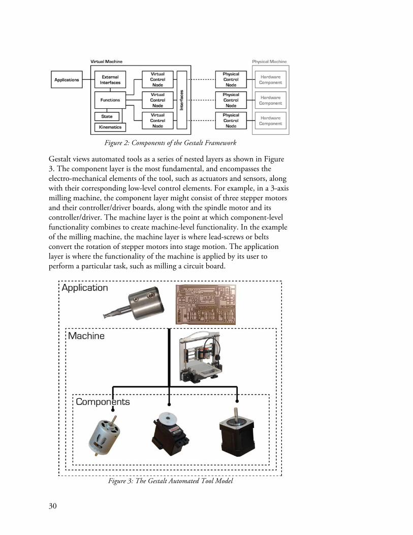
30
Figure 2: Components of the Gestalt Framework
Gestalt views automated tools as a series of nested layers as shown in Figure 3. The component layer is the most fundamental, and encompasses the electro-mechanical elements of the tool, such as actuators and sensors, along with their corresponding low-level control elements. For example, in a 3-axis milling machine, the component layer might consist of three stepper motors and their controller/driver boards, along with the spindle motor and its controller/driver. The machine layer is the point at which component-level functionality combines to create machine-level functionality. In the example of the milling machine, the machine layer is where lead-screws or belts convert the rotation of stepper motors into stage motion. The application layer is where the functionality of the machine is applied by its user to perform a particular task, such as milling a circuit board.
Figure 3: The Gestalt Automated Tool Model

31
The approach adopted by Gestalt is that of a virtual machine controlling a real machine. The virtual machine is a computer-based representation of the physical machine that often times will run on the user’s computer. Machine configuration and state is stored in the virtual machine, rather than in the physical hardware which controls actuators and reads sensors. The virtual machine approach has advantages over traditional machine controllers in every step of the chain of building and using automated tools, benefitting four primary types of users corresponding to the layers of Figure 3: the component controls builder, the machine builder, the application designer, and the end user. Sometimes these will all be the same person! The Component Controls Builder : Components form the physical language from which an automated tool is built. Common electro-mechanical components include stepper motors, DC motors, limit switches, relays, and a variety of task-specific actuators and sensors. In order for these components to interface with the greater control system, they often require a control board that abstracts away the details of their operation. For example, a stepper controller might accept a logical command like “spin 100 steps at a rate of 10 steps/sec” and converts that command into the low-level pulses of current that cause the motor to move accordingly. Typical controllers accept these high-level commands over a physical interface like a serial port, requiring that all of the command processing occurs on the hardware of the controller (Figure 4).
Figure 4: A traditional approach to component control.
The virtual machine approach assists the component control builder by allowing them to own both sides of the physical interface. The control builder writes both device-based firmware and a matching computer-based device driver as shown in Figure 5.
Figure 5: The Gestalt approach to component control.
This makes the task of writing firmware easier, and permits the firmware to run more efficiently, by allowing complex calculations to be written in a

32
language like Python and performed on the computer, while time-sensitive calculations, like when to take a step, are performed in firmware. In the language of Gestalt, the physical controller is known as a node, and the computer-based driver is a virtual node. A set of Gestalt libraries written in C and Python handle communication between nodes and virtual nodes respectively. Device drivers can also be written for pre-existing hardware that uses the traditional approach shown in Figure 4, without utilizing the Gestalt communications libraries or protocol. The Machine Builder : The machine builder uses Gestalt to create controllers for automated tools. The task of these controllers is to unify the components of the machine into a cohesive whole, and to present a high-level interface to external applications.
Figure 6: A Three-Axis Machine Controller
For example, an individual might be building a three-axis positioning stage using three stepper motors as shown in Figure 6. A machine controller is needed which can synchronously control these motors to cause the stage to move, and also exposes an API to task-specific applications that wish to control the machine. This controller is referred to as the virtual machine because it is a software representation of the physical machine. The virtual machine approach of Gestalt makes it easy for a machine controller to talk to machine components such as stepper motors simply by importing and then making function calls on their device drivers. Control nodes for various discrete components like stepper motors can be plugged into a common bus, and Gestalt has built-in provisions for synchronizing the activity of these nodes. For example, each of the three stepper motors of Figure 6 can be controlled by a separate physical controller, yet Gestalt makes them appear to the virtual machine as a single logical 3-axis controller rather than three 1-axis controllers. The ability to plug individual components into a network and have them be treated as a cohesive unit promotes modularity and reuse because control boards can be built with finer granularity to support single

33
components that later get combined by the virtual machine to control entire tools. In order to convert between motor coordinates and machine coordinates, a mechanics library has been created which includes common machine kinematics like the differential-drive h-bot, and transmission elements such as lead-screws and pulleys. Pre-built machine-level functions like “move” allow the machine control builder to rapidly test out their creation, and also include more advanced functionality such as accel/decel path planning with look-ahead. The modular approach of Gestalt means that virtual nodes, kinematics, and functions can all be shared and reused. In many cases this can significantly reduce the amount of work necessary to implement a new machine controller. The Application Designer : Applications provide a task-specific context in which a user interacts with a tool. For example, the web-browser-based application shown in Figure 7 generates toolpaths for milling circuit boards and provides related machine-control functionality like jogging and zeroing the tool.
Figure 7: A Browser-Based PCB Milling Application
Gestalt’s approach to machine control makes it easy for applications to interface with the virtual machine (and thus the real machine) either by importing the virtual machine as a Python module, or by connecting to the virtual machine thru a remote procedure call interface. The former modality is well-suited for experimentation or algorithmic machine control because the

34
application can call functions on the machine just as you would on any other Python method. This approach does away entirely with industry-standard G-code because function calls are made directly. The remote procedure call interface provides a way of converting an HTTP request into a machine function call which returns a response encoded in JSON. This enables the development of browser-based interfaces to machine tools, as in Figure 7, which in turn could open the door to a wide variety of new applications that are partially browser-based and partially server-based. An example of this use case might be an online repository for storing PCB designs, which is also able to directly control a user’s machine. Web-based UIs have the advantage of being operating-system independent and written in a language set (HTML/CSS/Javascript) that has a shallow learning curve, has prolific online support, and has enormous momentum driving its further development. An additional benefit of the virtual machine approach, not explored by this thesis, is the fact that the capabilities of the real machine are exposed via the virtual machine to the application. This could enable a new generation of toolpath generation software that looks at not only the geometry but also the capabilities of the machine when coming up with a strategy for how to produce the part. For example, an application might be capable of generating toolpaths for a CNC mill and a 3D printer, and would choose between the two methods based on the virtual machine provided to it. A less ambitious use case is a 3D printer slicing engine that identifies that the work volume of the machine is smaller than the size of the part, and thus automatically splits the part up into several pieces. The Tool User : The primary benefit of the virtual machine approach to the tool user is that the inner workings of the machine, down to the component level, are made open to them. This enables machines to be repurposed for new applications by the end user, or allows the end user to learn from the construction of existing machines in support of their own machine development efforts. In essence, Gestalt allows the tool user to readily assume the three other roles mentioned previously. For example, the user becomes an application developer simply by importing the virtual machine into a Python script. This use case is particularly relevant in cases where the design of an object is expressed by its designer in terms of how it is fabricated. A biologist might specify a wide range of titrations or a combinatorial matrix of solutions. These ‘objects’ are already conceptualized by the biologist as the protocol necessary to create them. Thus the easiest way to communicate the protocol to a robotic pipette may indeed be via a short script.

35
The Virtual Machine Model
Nodes
Gestalt as a framework is built around the notion of virtual nodes controlling physical nodes over an interface (Figure 8). Conceptually, this allows real hardware to be treated as software objects, conferring all of the benefits of object-oriented programming including modularity, reusability, and re-configurability.
Figure 8: Virtual and Physical Nodes
From the perspective of the hardware designer, the virtual machine approach has an additional benefit. Because the virtual node and the physical node occupy both ends of the communication channel, the hardware designer has complete control over what information is sent over the wire. This enables them to perform computationally-intensive calculations in the virtual node, preserving compute power on the physical node for time-critical operations. Four classes of nodes are defined in Gestalt, corresponding to a variety of scenarios and connection topologies.
Solo/Independent Nodes
Figure 9: Solo/Independent Node
The most basic type of virtual node is the solo/independent node (Figure 9), and is used when it is necessary to interface pre-existing non-Gestalt hardware. The role of the virtual node in this case is to provide an API wrapper for whatever API is already provided by the hardware. For example, the author has written solo/independent nodes for an industrial inkjet head that communicates over a serial interface using an ASCII-based command set, and for a KUKA robotic arm that communicates over Ethernet using

36
XML. Solo/Independent nodes cannot be synchronized by Gestalt and thus must rely on some other means of synchronizing with external hardware.
Solo/Gestalt Nodes
Figure 10: Solo/Gestalt Node
Solo/Gestalt nodes (Figure 10) communicate using a standardized packet format and respond to a common set of basic commands. These common commands include functionality for resetting the node, loading new firmware, and automatically loading a virtual node from a vendor’s website. This functionality is provided by a base class on the virtual machine side, and by a C library on the physical node side. Because the hardware designer creates the virtual node alongside the physical node, they are free to send whatever information they want over the communication channel. Solo/Gestalt nodes typically communicate over a USB (virtual serial port) connection although other mediums such as Ethernet or radio are possible. Solo/Gestalt nodes cannot be synchronized with each other using the Gestalt framework, at least given the presently implemented synchronization techniques.
Networked/Gestalt Nodes
Figure 11: Networked/Gestalt Node

37
Networked/Gestalt nodes (Figure 11) are very similar to Solo/Gestalt nodes, except that they communicate on a common bus that enables them to conduct synchronized activities. Physically, the nodes are interconnected using the FABNET standard that is discussed in more detail in Appendix C. Gestalt allows packets to be addressed to individual nodes or to all nodes on the network. Synchronization is accomplished by preparing each node for a coordinated activity by sending a unique setup packet to each node. A ‘multicast’ synchronization packet is then addressed to all nodes, signaling them to begin at precisely the same time. This method might be called ‘soft’ synchronization, and has drawbacks which are discussed later in this section and are demonstrated in the ‘Distributed Control of a Fabrication Machine’ case study. Addressing individual nodes requires a means of associating virtual nodes with their physical counterparts. The Gestalt Interface class manages the routing table that connects virtual and physical nodes, as well as additional tasks like queuing commands and generating synchronization packets.
Managed/Gestalt Nodes (tentative)
Figure 12: Managed/Gestalt Node
There are several anticipated problems with the Networked/Gestalt approach, stemming from round-trip latency. In order to ensure that all command packets have been received by the physical nodes before beginning a synchronized activity, it is necessary for them send a confirmation response. FABNET communicates using the differential RS-485 standard which is not collision-tolerant. Therefore the virtual node must wait for a response to its outgoing packet before releasing the interface to the next virtual node waiting
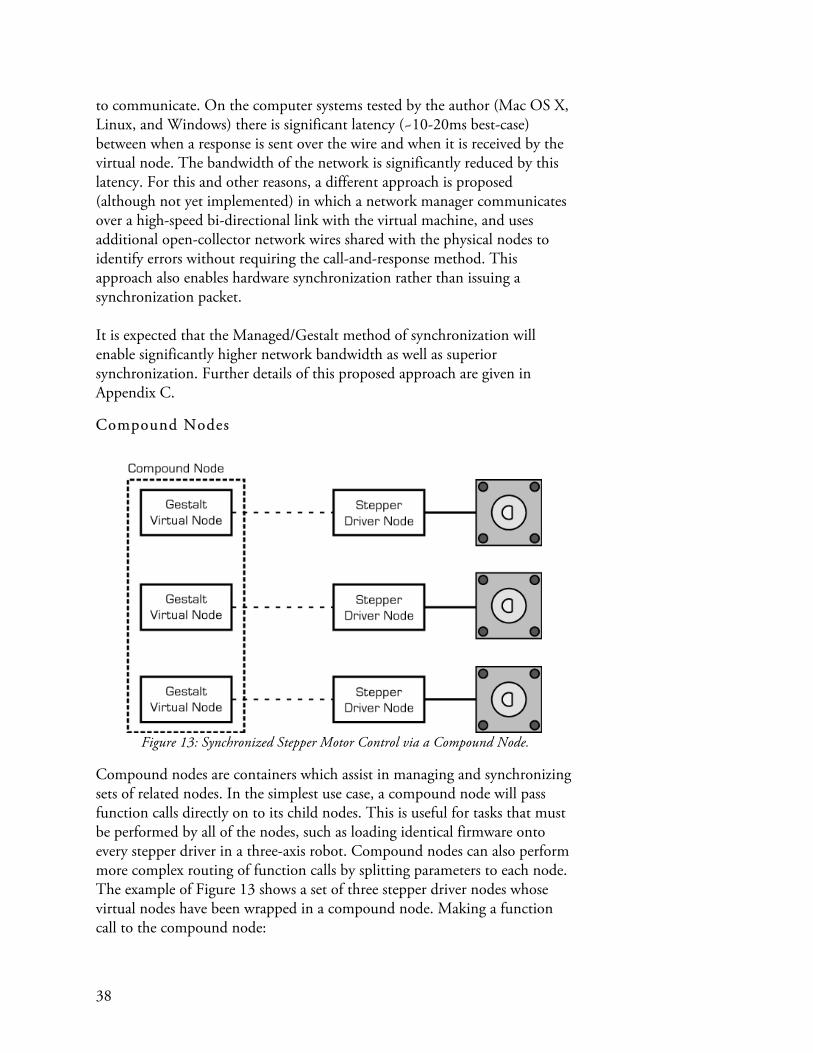
38
to communicate. On the computer systems tested by the author (Mac OS X, Linux, and Windows) there is significant latency (~10-20ms best-case) between when a response is sent over the wire and when it is received by the virtual node. The bandwidth of the network is significantly reduced by this latency. For this and other reasons, a different approach is proposed (although not yet implemented) in which a network manager communicates over a high-speed bi-directional link with the virtual machine, and uses additional open-collector network wires shared with the physical nodes to identify errors without requiring the call-and-response method. This approach also enables hardware synchronization rather than issuing a synchronization packet. It is expected that the Managed/Gestalt method of synchronization will enable significantly higher network bandwidth as well as superior synchronization. Further details of this proposed approach are given in Appendix C.
Compound Nodes
Figure 13: Synchronized Stepper Motor Control via a Compound Node.
Compound nodes are containers which assist in managing and synchronizing sets of related nodes. In the simplest use case, a compound node will pass function calls directly on to its child nodes. This is useful for tasks that must be performed by all of the nodes, such as loading identical firmware onto every stepper driver in a three-axis robot. Compound nodes can also perform more complex routing of function calls by splitting parameters to each node. The example of Figure 13 shows a set of three stepper driver nodes whose virtual nodes have been wrapped in a compound node. Making a function call to the compound node:

39
spin((100,200,300),accelSteps=50, decelSteps=50, accelRate=500) will result in three separate function calls being issued to the child nodes: spin(100, accelSteps=50, decelSteps=50, accelRate=500) spin(200, accelSteps=50, decelSteps=50, accelRate=500) spin(300, accelSteps=50, decelSteps=50, accelRate=500) Thus the compound node behaves externally like its constituent nodes, and in the example above could be a drop-in replacement for a single three-axis control node. Refer to the synchronization subsection for more information on how synchronization is handled internally.
Machine Functions
Figure 14: Machine-Level Functions
Virtual nodes are concerned only with providing functionality within the scope of their physical node. A stepper control node, for example, provides methods for spinning a motor rather than moving a machine. This is a fundamental difference between the virtual machine approach and that taken by the traditional CNC controller where machine configuration is embedded in the firmware running within the hardware of the controller. In order to begin building virtual machines from modular node elements, functions that operate on the entire machine must be provided. These machine-level functions need to be imbued with knowledge of the machine configuration, need a way of storing machine state (e.g. machine position) and must be connected to the nodes which they will control.
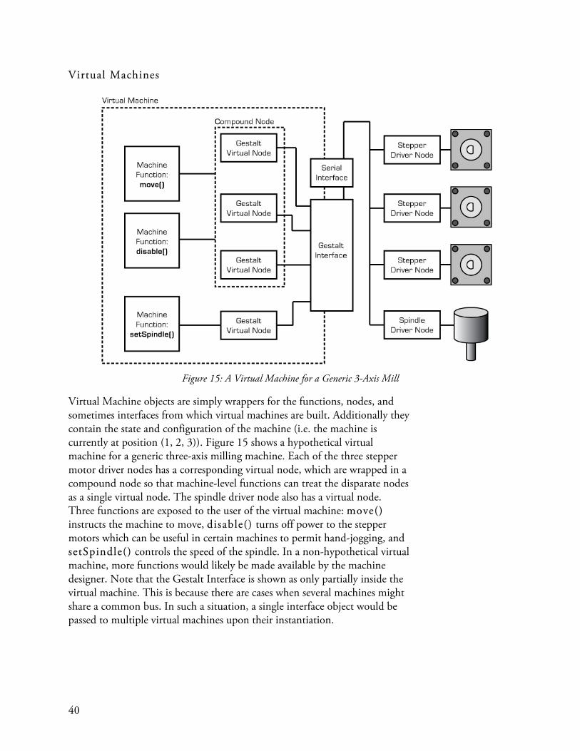
40
Virtual Machines
Figure 15: A Virtual Machine for a Generic 3-Axis Mill
Virtual Machine objects are simply wrappers for the functions, nodes, and sometimes interfaces from which virtual machines are built. Additionally they contain the state and configuration of the machine (i.e. the machine is currently at position (1, 2, 3)). Figure 15 shows a hypothetical virtual machine for a generic three-axis milling machine. Each of the three stepper motor driver nodes has a corresponding virtual node, which are wrapped in a compound node so that machine-level functions can treat the disparate nodes as a single virtual node. The spindle driver node also has a virtual node. Three functions are exposed to the user of the virtual machine: move() instructs the machine to move, disable() turns off power to the stepper motors which can be useful in certain machines to permit hand-jogging, and setSpindle() controls the speed of the spindle. In a non-hypothetical virtual machine, more functions would likely be made available by the machine designer. Note that the Gestalt Interface is shown as only partially inside the virtual machine. This is because there are cases when several machines might share a common bus. In such a situation, a single interface object would be passed to multiple virtual machines upon their instantiation.

41
There are several ways of interacting with virtual machines. The first is by importing them as modules into a user program. For example, a user could write a short program: import threeAxisMill myMill = threeAxisMill.virtualMachine() myMill.move([20, 20, 20], velocity = 100) that would import the machine as a Python module, create an instance of the virtual machine, and then instruct the virtual machine – and thru it the real machine – to move to a position of (x=20mm, y=20mm, z=20mm) at a velocity of 100mm/sec. Another method of interacting with the virtual machine is via a remote procedure call (RPC) interface, which allows a restricted set of function calls to be made on the virtual machine by external sources. Two applications of the RPC interface have been explored: RPC-over-HTTP (Figure 16), and RPC-as-a-file.
Figure 16: RPC-over-HTTP
RPC over HTTP converts standard HTTP requests into function calls, which are then executed on the virtual machine. If values are returned by the virtual machine, they are encoded as JSON and sent as a response to the initial request. The RPC interface provides a safe way of exposing an API to browser-based user interfaces without allowing arbitrary code to be run on the user’s computer. When using an RPC-over-HTTP interface, the virtual machine could be run as a standalone Python program rather than imported as a module. It may become common practice for every virtual machine to detect if it is running in standalone mode and, if so, to begin an RPC interface. While RPC-over-HTTP is well-suited for user interface tasks like jogging a machine or turning on and off a spindle, the protocol has been found to be ill-suited for high-speed transmission of commands as might be encountered when 3D surface milling a part. One solution to this problem is to compile a long sequence of function calls into a single file, and then to pass them to the RPC-as-a-file interface for execution on the machine. Conceptually this approach is similar to that taken by G-Code, but function calls serialized as text can provide a more open and unrestricted language for controlling

42
machines. The downside of using function calls instead of G-code is that standardization is not enforced by the language, meaning that it is up to the virtual machine builders to arrive at a standard set of commands for their given domain. For example, G-code defines G1 X0 Y1 Z2 to mean “move to position (1,2,3)”, whereas each machine builder could hypothetically define a different function to perform this same task. The question of how to enforce standards to enable interoperability of applications and machines is still open.
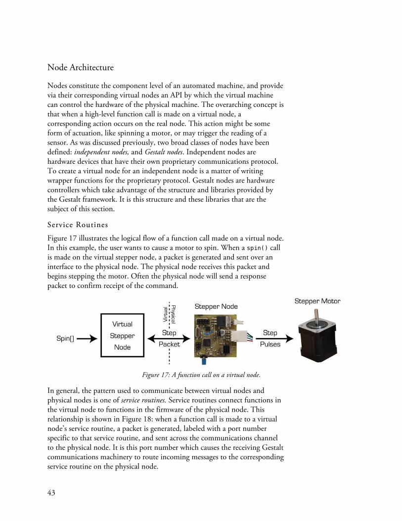
43
Node Architecture
Nodes constitute the component level of an automated machine, and provide via their corresponding virtual nodes an API by which the virtual machine can control the hardware of the physical machine. The overarching concept is that when a high-level function call is made on a virtual node, a corresponding action occurs on the real node. This action might be some form of actuation, like spinning a motor, or may trigger the reading of a sensor. As was discussed previously, two broad classes of nodes have been defined: independent nodes, and Gestalt nodes. Independent nodes are hardware devices that have their own proprietary communications protocol. To create a virtual node for an independent node is a matter of writing wrapper functions for the proprietary protocol. Gestalt nodes are hardware controllers which take advantage of the structure and libraries provided by the Gestalt framework. It is this structure and these libraries that are the subject of this section.
Service Routines
Figure 17 illustrates the logical flow of a function call made on a virtual node. In this example, the user wants to cause a motor to spin. When a spin() call is made on the virtual stepper node, a packet is generated and sent over an interface to the physical node. The physical node receives this packet and begins stepping the motor. Often the physical node will send a response packet to confirm receipt of the command.
Figure 17: A function call on a virtual node.
In general, the pattern used to communicate between virtual nodes and physical nodes is one of service routines. Service routines connect functions in the virtual node to functions in the firmware of the physical node. This relationship is shown in Figure 18: when a function call is made to a virtual node’s service routine, a packet is generated, labeled with a port number specific to that service routine, and sent across the communications channel to the physical node. It is this port number which causes the receiving Gestalt communications machinery to route incoming messages to the corresponding service routine on the physical node.

44
Figure 18: Service Routines
Service routines are typically decoupled from each other, which lends a measure of modularity to the programming of nodes. Functionality can be added to a node simply by dropping in additional pre-written service routines.
Message Packets
A standard message packet format has been defined, shown in Table 1, which facilitates delivering arbitrary data between service routines on virtual and physical nodes, both when the nodes are solo or when multiple nodes are connected on the same physical network.
Table 1: The Gestalt Base Packet
The first byte of every Gestalt packet is a start byte . This is used both to indicate to the receiving nodes that a new packet is starting, as well as to identify whether the packet is directed to a specific node or whether it should be received by all nodes. The following two address bytes indicate the node to which the packet is intended. The port byte, just discussed, directs the packet to the attention of a particular service routine within the addressed node. A length byte indicates to the receiver machinery how many bytes it should expect to receive. Following the length byte is an arbitrary number of (but less than 249) payload bytes . The payload is the core of the packet, and is used by the service routines to pass messages like how many steps to take or the current value of a sensor. The final byte is the checksum byte.

45
This is generated using a cyclic redundancy check (CRC) algorithm which aids in detecting whether the packet has become corrupt during transmission.
Physical Node Packet Handling
When a start byte is received by a physical node, its receiver begins listening for the rest of the packet. Simultaneously, a watchdog timer is started that will reset the state of the receiver should the next byte never arrive. Once a complete packet with a correct checksum has been received, the receiver looks at the packet’s start byte. If the start byte indicates that the packet is unicast, the receiver checks the address bytes to determine if the packet is intended for the node. Should these bytes match, the destination port of the packet is examined and the appropriate service routine is called. The service routine then pulls the packet’s payload from the receive buffer and acts upon it. If the start byte indicates that the packet is multicast, the node calls the appropriate service routine irrespective of whether the address bytes in the packet match the address of the node. Being able to send packets to multiple nodes simultaneously is an important aspect of one of the synchronization techniques used by Gestalt to coordinate actions like stepping motors across disparate controllers. When a service routine wants to transmit a response to an incoming packet, it fills the node’s transmit buffer with data and then calls the transmit() function. This causes a packet to be automatically addressed to the virtual node and sent over the interface. A firmware library has been written in C and provides all of the functionality shown in Figure 19 for receiving, transmitting, and routing packets. A number of base service routines are also provided for performing fundamental functions like loading new firmware and discovering nodes. However it is up to the node’s builder to write their own service routines to extend the functionality of the base node for their particular task.

46
Figure 19: Physical Node Packet Handling
Virtual Node Packet Handling
The way in which packets are handled by the virtual machine is slightly more complex than the physical nodes because of the one-to-many relationship between the virtual machine interface and the physical nodes. One interface may host many nodes, as in the case of the networked bus, but each node only has one interface. This means that the virtual machine interface is responsible for routing packets to the correct virtual node, where they are then routed to a service routine. When a packet is received by a virtual machine interface, it is first checked for errors. If the packet’s checksum is valid, the packet is sent to a separate thread which routes it to the correct virtual node based on its address bytes. The address-binding table which associates addresses with nodes is a part of the interface because of the one-to-many relationship discussed earlier. The packet is then sent to the port router in the destination virtual node where a port table is consulted to determine the proper service routine. Each port is associated with two service routines: one outgoing routine, and one incoming routine. When a packet is received on a particular port, the associated incoming routine is called. Additionally a flag is set which notifies the outgoing routine that a packet has been received. This feature is important because often outgoing routines like spin() require that the node respond to confirm receipt. The outgoing routine will block until the incoming packet flag has been set. Figure 20 illustrates this process.
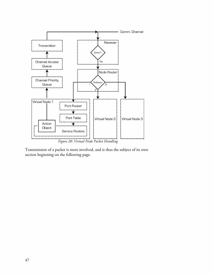
47
Figure 20: Virtual Node Packet Handling
Transmission of a packet is more involved, and is thus the subject of its own section beginning on the following page.

48
Action Objects
When a function call is made to a virtual node’s service routine, a packet is generated and sent to the matching service routine on a physical node. The path between the function call and the packet’s transmission is not straightforward, however.
Figure 21: Action Objects - from Instantiation to Transmission
Whenever a call is made to a service routine, an action object is instantiated. This behavior is a bit surprising, as you might expect a packet to be generated and transmitted. Action objects do contain a packet, but also contain the logic that generated the packet. It is important that the logic and the resulting packet get bundled together because occasionally the packet needs to be updated after having been generated. For example, when controlling the motion of a milling machine, algorithms are often used to adjust the speed of the machine as it moves into sharp corners to limit sudden accelerations or decelerations. These algorithms rely on looking ahead a certain number of moves to predict when a sharp corner is on the horizon, and taking action in advance. In this case, there is a significant lag between when a motion packet is first generated and when its final form has been decided based on the accel/decal algorithm. Bundling packets with their generating logic in an action object allows these updates to be made easily. Action objects also permit packets to be synchronized with each other by allowing the packets to be updated with synchronization information after they have been created. Action objects have three methods which control their behavior as it relates to transmitting a packet: commit(), release(), and channelAccess(). Commit() causes the action object to place itself in the interface’s channel priority queue. This queue acts as something of a holding pen. Action objects will always

49
leave the queue in the same order in which they arrive (first in first out). However, an action object can only leave the channel priority queue when its release() method is called. This allows other processes to finish any calculations which may update the action object’s packet before releasing it and thus giving it permission to transmit its packet. When the release() method is called, the action object enters the channel access queue. It is here that the action object is waiting for a turn to transmit its packet. When this moment arrives, the interface will call the action object’s channelAccess() method. This gives the action object access to the communication channel for as long as it might need, including an opportunity to transmit several times if it does not receive an expected response. When the channelAccess() method returns, the next action object waiting in the channel access queue is triggered to transmit. This entire process is depicted in Figure 21. In addition to action objects themselves, there are two containers for action objects called action sequences and action sets. These are shown in Figure 22.
Figure 22: Action Object Containers
Action sequences contain a set of action objects that should be executed serially. The need for this structure arises when a call to a service routine generates more than one action object. For example, a call to spin() requests that a motor take 1000 steps. However the packet format between the virtual motor controller and the physical motor controller only supports a maximum of 255 steps. Thus a single call to spin() requires four packets, and therefore four action objects, to transmit the request for 1000 steps to be taken. Action sets contain a set of action objects which should be executed simultaneously. This occurs when multiple nodes are to be synchronized together. Action sets can be composed of action sequences instead of action objects. Both action sets and action sequences can be committed to the channel priority queue. However, when a release() method is called on these containers, a compilation step is performed to serialize their action objects and place these in the channel access queue.

50
Figure 23: Serializing Action Sets and Action Sequences
The serialization of an action sequence is straightforward, as the action objects contained within are already in a serial sequence. The process of serializing an action set, shown in Figure 23, is a bit trickier. Action sets containing action sequences are first sliced across the sequences. In the example of Figure 23, the slices would be [A1, B1, C1], [A2, B2, C2], and [A3, B3, C3]. Each of the action objects within the set is then synchronized with each other. An additional synchronization action object is generated for reasons discussed in the following subsection, and the complete set is released to the channel access queue.
Synchronization
The ability to synchronize the behavior of multiple nodes over a network is crucial to realizing a number of the benefits of hardware modularity. There are two steps to synchronization. The first is the decomposition of multi-node actions into individual instructions for each node. This step is discussed in the sections preceding this one. The next step is to make these actions occur simultaneously on separate controllers. Successfully accomplishing this involves having a shared notion of time across all nodes, and a simultaneous moment on which all of the actions begin. Appendix A discusses how motion commands (and more generally any command) can be decomposed into separate node commands that share a common virtual major axis. The virtual major axis is simply a common time base on which all actions are timed. The final step, synchronizing the start time of each move, is accomplished by transmitting individual instructions to each node followed by a multicast

51
‘start now!’ packet that is received by all nodes simultaneously. Because each node shares a time base and a start time, their actions will be synchronized within the tolerance of the microcontroller’s crystal clock. The overall process of synchronizing distributed actions is shown in Figure 24.
Figure 24: Synchronized and Distributed Actions
As with typical packets, each configuration packet requires a response packet to ensure receipt. The synchronization packet does not elicit a response, which leaves open the possibility that it gets missed by one node but not others. Because a response is required of the configuration packets, communications latency becomes a problem. It is possible to buffer synchronized moves in the physical nodes, but at the risk of clock drift. A further explanation of this phenomenon, and a proposed solution to latency issues during synchronized moves, is presented in Appendix C as the Managed/Gestalt node type. The need for this conceptual work is corroborated in the ‘Distributed Control of a Fabrication Machine’ case study, where evidence was found that even for moves with moderate detail, latency became a dominating factor in limiting tool speed.
Virtual Node Shell
Much effort has already been expended describing the inner workings of the virtual node object, particularly in the context of communication with its physical counterpart. Here we discuss the virtual node in the context of the virtual machine. When a virtual node is defined inside a virtual machine, a bit of a trick is played. Rather than a virtual node, a virtual node shell is created. This shell passes along function calls made on it to a virtual node contained inside. When the virtual machine is first started up, the shell is filled with a generic virtual node that contains just enough functionality to ask its matching physical node for a pointer to the file containing the physical node’s specific virtual node. This specific virtual node is then instantiated and

52
swapped with the generic virtual node, thus allowing the virtual machine to access all of the unique functions of the physical node. The virtual node shell technique is used because all of the machine-level functions need to be provided on startup with a reference to a virtual node that does not change (else all of the references would need to be changed when the specific virtual node is acquired). This approach permits a static shell whose ‘meat’, the virtual node, can be swapped at will. Because the shell passes along any function calls onto the contained virtual node, the shell is essentially transparent. Figure 25 shows the virtual node shell schematically.
Figure 25: Virtual Node Import Internals

53
Related Work
Gestalt sits at the intersection of several established domains, in which there exists a large collection of relevant work. This section pulls from academic literature, the commercial market, and the DIY community to place Gestalt within the greater context of what has been done before.
Control Frameworks
Significant work has already been done to enable the rapid creation of control systems, both for the industrial manufacturing market and also as a tool for academic research. Gestalt touches on both areas because it aims to enable the rapid development of automated fabrication tools (as in industrial manufacturing), but for an audience and purpose more closely related to academia – the intended user is primarily an individual who, like the researcher, is seeking to widen the boundaries of their capabilities. There is quite a bit of interest within the industrial manufacturing arena for frameworks that enable rapid creation of control systems for new tools. This is driven by demands for specialized and highly automated machinery for production, and also by the high cost of developing unique special-purpose software to control these machines (Pritschow et al., 2001). The general solution converged upon by industry is one of vendor-neutral modularity, achieved through a standardization of interfaces at a software level, and is commonly referred to as Open Architecture Control (OAC). Several frameworks to implement this general concept have been developed, and include the Open Systems Environment Consortium (OSEC), the Open Modular Architecture Controllers (OMAC) users group, and the Open System Architecture for Controls within Automation Systems (OSACA) project (Pritschow et al., 2001). Some of the most relevant work to Gestalt is in this field of industrial tool construction, and was conducted by Kevin Oldknow and Ian Yellowley at the University of British Columbia5. They describe an approach which enables the ‘dynamic reconfiguration’ of machine tool controllers using a virtual machine controlling a physical machine (Oldknow & Yellowley, 2001). Their system is very similar to Gestalt in many ways. Each hardware component, such as a physical motion axis, is represented to higher-level 5 The author regrets to have only discovered this work after the development of Gestalt, as many of the concepts presented by Oldknow and Yellowley are important aspects of Gestalt and took significant effort to arrive at independently. It is interesting, however, that pursuing the same problem has led to such similar solutions.

54
applications as a virtual component. A set of standard object classes ensure that these virtual components are interchangeable. This is a feature still lacking in Gestalt – while base classes and standard libraries are used to ensure that all nodes contain the basic functionality needed to communicate with their physical and virtual counterparts, there is currently no enforcement of a standard API that is presented by specific types of virtual nodes such as stepper motor control nodes, etc. Just as Gestalt nodes define their own virtual machine drivers and thus can send arbitrary data over the network, in the system created by Oldknow and Yellowley, hardware components store within their firmware the drivers needed by the virtual machine to talk with them. On start-up, these drivers are pushed over the communications bus to the virtual machine where they are subsequently used to talk to the hardware from which they were downloaded. Gestalt’s approach to node driver acquisition is fundamentally the same, although a URL that points to the driver is provided rather than the driver itself. One primary difference between the two systems is in the implementation of the virtual components. In Gestalt, the virtual nodes interface between higher level code (like the virtual machine) and the physical hardware. In Oldknow and Yellowley’s system, the virtual component and its software-based hardware driver are separated from each other and linked by a binding-table. This overall system was later developed into a commercial product by Cameleon Controls (Ramin Ardekani, Oldknow, & Yellowley, 2011). Several frameworks have been developed for research use that facilitate the rapid prototyping of control systems. One such system is produced by National Instruments and is called LabView (National Instruments, 2013). LabView is a generic framework for building and testing control systems. A graphical interface allows users to instantiate a wide variety of modular blocks and then connect them to achieve specific functionality. This visual code is then compiled and executed in conjuncture with specialized LabView interface hardware. For example, the control system for a robotic arm could be created by creating individual PID controllers for each motor, and then connecting them through a pre-defined kinematics matrix to an input stream of XYZ coordinates. Motor amplifiers and sensors would be attached to the LabView interface hardware. While LabView is extremely flexible, and in terms of functionality is capable of the same things as Gestalt and more, its cost and complexity make it ill-suited for our intended audience. Within the more specific realm of robotics (in which automated tools might be viewed as a subset), a number of frameworks exist that help developers interface with, and control, systems built from a heterogeneous mix of hardware devices. The Robot Operating System (ROS), largely developed by

55
Willow Garage, is an example of an open-source framework for robotics research. It provides services such as “hardware abstraction, device drivers, libraries, visualizers, message-passing, package management, and more.” (Willow Garage, 2013). Like Gestalt, components are modularized as nodes. Nodes communicate using a publisher/subscriber paradigm where any node can publish information to a ‘topic’; this information is subsequently received by any nodes that subscribe to that topic (ROS, 2013). It is quite likely that ROS could be adopted to the more specific tasks of controlling automated tools, and the fact that it is open-source puts this prospect in the hands of the community. It certainly seems to have many of the desired properties, such as the ability to control disparate hardware in real time from a programming interface.
Rapid Prototyping of Personal Fabrication Machines
Since 2009, an ongoing project at the MIT Center for Bits and Atoms (CBA) called ‘Machines That Make’ (MTM) has been developing a complete workflow for personal fabrication, from CAD through toolpath generation and machine control. Nadya Peek, a current graduate student in the CBA, is currently also working on virtual machine control of physical machines over distributed networks of nodes (Peek, 2012). In addition, a large number of low-cost machines have been built in conjuncture with the MTM project including a DIY EDM machine by Ben Peters, a 5-axis desktop milling machine by James Coleman, a multi-process lathe capable of 3D printing in polar coordinates, by Yoav Sterman, a cast-cement CNC gantry by Kenny Cheung, and others (MIT-CBA, 2013). Some of the early work which led to Gestalt occurred as part of the MTM project, including some of the first versions of the virtual machine controlling a set of networked nodes. Prior to the MTM project, the first seeds of Gestalt took root as the author worked on their senior thesis under the supervision of Professor Gershenfeld. This work developed a distributed controller for a small PCB mill that was controlled by a virtual machine (Moyer, 2008). The RepRap project is another example of the rapid construction of personal fabrication tools by individuals (Reprap, 2013). The goal of the RepRap project is to create a 3D printer design that can self-replicate: the majority of the parts needed for the machine can be printed on the machine. The result has been a Cambrian explosion of home-made 3D printer varieties (Gilloz, 2012).

56
Browser-Based Control
The idea of web-browser based machine tool control was first suggested to the author in conversations with Ed Baafi, who is one of the creators of Modkit – an online integrated development environment for programming microcontrollers (Modkit, 2013). Indeed, the browser-based applications shown throughout this thesis are inspired by Modkit’s approach. The Modkit user interface is a browser-based application that loads programs onto a microcontroller through a small Python application running on the user’s computer.
Figure 26: Browser-Based Control
Figure 26 illustrates the concept of browser-based control. A web page residing on any server (including the local file system) is visited by a web browser. That web page uses the browser to communicate to the tool as needed. In the case of Gestalt, this interaction occurs through communications between the web browser and the remote procedure call interface of the tool’s virtual machine. The virtual machine may be local to the web browser, or may even reside on a separate computer like a Raspberry Pi (Raspberry Pi Foundation, 2013).
Figure 27: Web-Based Control
There has additionally been quite a bit of work recently in Internet-controlled tools. In this scheme, the tool is not local to the browser. Frequently, the tool is connected to the same server which provides the user with the webpage needed to control the tool (Figure 27). One example of this is OctoPrint (Haussge, 2013). Octoprint is a machine interface for 3D printers which acts as a web server, publishing its controls in the form of a webpage. Users are thus able to control their 3D printer remotely from a web browser. The difference in approach between Octoprint and Gestalt is that Octoprint publishes the webpage needed to interface with Octoprint. With Gestalt, a 3rd party publishes the webpage which controls Gestalt. It is logical to extend browser-based control into an entire workflow including part design, toolpath generation, and machine control. A research

57
group at the University of Berkeley has made large strides in this direction with their ‘CyberCut’ system (Smith & Wright, 1996). They present a system which includes internet-based CAD, process planning, and toolpath generation. Additionally they show how knowledge of the manufacturing process can be fed back into the CAD program to prevent the designer from creating un-manufacturable geometry. This concept is particularly relevant to Gestalt, where rich information on the capabilities of the tool could be made available to upstream workflows by the virtual machine.
Hardware APIs
One of the primary aspects of Gestalt is that it enables software APIs for physical hardware. A number of projects have conducted related work. Firmata is an Arduino library that allows host computers to control an arduino using high-level function calls (Firmata, 2013). Moti is a “smart motor” which can be networked and which exposes an API that can be interfaced with from a web browser (Motiph, 2013). Phidgets is very similar to the node layer of Gestalt; a wide variety of commercially available USB-connected hardware modules can control actuators and read sensors. Each module comes with a matching host API that can be called from applications written in a wide variety of programming languages including Java, C++, LabView, Python, Ruby, and more (Phidgets, 2013).


59
Development: Challenges and Solutions
Gestalt has been in development, in one form or another, for nearly four years. Over this period, around eight iterative versions have been created. The task of architecting a framework is challenging because above all else the framework must be self-consistent. When a new requirement is added, or a more elegant way of accomplishing a task is found, the framework may need to be redesigned from the ground up to maintain consistency. Just as Gestalt is intended to promote a more open design philosophy towards machine design, much care has been taken so that Gestalt itself is easily modified. This section presents several of the challenges encountered over the course of Gestalt’s development, and discusses the solutions that have been adopted.
Conception
The idea for a virtual machine controlling a physical machine over a network was first suggested to me as the topic for my B.S. thesis by Prof. Neil Gershenfeld of the MIT Center for Bits and Atoms. The exploration that ensued did not focus on making a framework – at the time the author was more interested in understanding how to represent a machine in software. Perhaps the first seed of Gestalt came a year later when, as part of the MIT class ‘How to Make Something that Makes Almost Anything’ taught by Prof. Gershenfeld, the author met Steve Leibman. It was during a discussion with him that we realized that rather than machine tools executing G-code, which has no extensibility, they would be better off executing Python. We thought that this could enable the rapid development of more complex machines by allowing their control systems to tap into the functionality of the many available Python libraries. The core idea of the user being able to call Python functions on the virtual machine has dictated the overall architecture of Gestalt.
Synchronous, Not Real-Time
The key tension in the design of Gestalt is caused by the fact that the virtual machine is connected to the physical machine over an interface with significant intrinsic latency. This requires that heavy buffering is utilized on the hardware side in order to smooth out periods of high traffic and thus increase overall throughput. Yet the use of buffering causes lags in state between the virtual machine and the physical machine. Issues further arise because of the need for the virtual machine to synchronize the physical nodes in spite of this phase lag. One solution might be to make the system real-time: in such a configuration, the virtual machine would regularly and frequently push state to the physical nodes. However this would require both
60
a low-latency interface and also potentially a real-time operating system to ensure that the virtual machine was always able to meet its commitments for updating the physical nodes. This approach was avoided from the outset because of these practical concerns. No good solution to this problem has yet been found, but the author wishes to make the reader aware of this tension because it explains many of the design choices taken in the internal architecture of Gestalt. One example of such a choice is the decision that each service routine call generates not only a packet for transmission, but also an associated action object. These action objects help mitigate issues of state lag between the virtual and physical nodes because they allow commands that are currently waiting for execution in the buffers of the physical nodes to persist inside the virtual machine until their execution can be confirmed. This is useful in the event that state needs to be recovered. For instance, if a toolpath is paused by the user, the commands in the physical node buffers still have virtual representatives that can be used to determine the machine’s actual position. These action objects can also be pushed back onto the channel access queue so that the toolpath can be resumed where it was left off.
Virtual Node Acquisition
One of the early decisions in the development of Gestalt was that the person who designs the physical node should also write a matching virtual node. This allows the node designer to arbitrarily divide computation between the virtual and physical nodes, permitting complex calculations to be written in Python and executed on a fast processor while timing-critical operations like stepping a motor can be done on the physical node. Arbitrary packet payloads can be sent across the network because the node designer owns both ends. Additionally, the virtual node provides the machine builder with a modular and easy interface for communicating with physical nodes. The virtual node / physical node approach raised a few questions, however. One question is how does the virtual machine get the Python file containing the virtual node that corresponds to the physical node it wishes to control? Ideally, the user can plug a physical node into the network and the node automatically sends over its virtual node file when it is instantiated by the virtual machine. This is the implementation developed by Oldknow and Yellowley (Oldknow & Yellowley, 2001). The problem with this approach is that current low-cost microcontrollers have a limited amount of memory, some of which is already needed to store firmware. The solution that was adopted is for the physical node to send, on instantiation, a URL pointing to its virtual node file, presumably residing on the node manufacturer’s website. The virtual machine then downloads and imports the virtual node file, which it subsequently uses to control the physical node.

61
The second challenge associated with acquiring the virtual node relates to the chicken-and-egg situation of needing to talk to the physical node before having the virtual node needed to talk to it. When the virtual machine instantiates a virtual node object, it actually creates a container for a virtual node. That container is automatically filled with a base virtual node that contains just enough functionality to associate with and get a URL from the physical node. As long as the physical node’s firmware was compiled with the Gestalt C library, the service routines required by the base virtual node to get a URL will be on the physical node. Once the URL is received by the virtual machine, the container contents are swapped with the manufacturer-supplied virtual node object. One final challenge with the container approach is that from the perspective of the virtual machine, the container is the virtual node. Thus there needs to be a way for the container to act as if it is the virtual node, meaning that any function calls made on the container should be forwarded onto the virtual node. Fortunately, Python provides the functions __getattr()__ and getattr() which do precisely this.
Node Pairing
One of the first steps which must occur before a virtual node can talk to a physical node is that the two need to be associated together. Imagine a new three-axis machine which is being tested for the first time. Each stepper motor is its own node on a network. The virtual machine correspondingly has three matching virtual stepper nodes. But which virtual node controls which physical node? This problem is two-headed. First, each physical node needs a unique address to be used in the pairing. Second, each virtual node needs to know the address of the physical node which it controls. The original method for picking unique network addresses was borrowed from the Internet Zero project (Gershenfeld & Cohen, 2006), where hundreds of nodes requiring unique addresses might exist on the same network. His solution was that when each node powered on, it began an endless counter loop. The user would press a button on the node to break out of the loop, and the value of the counter was stored as the node’s address. Because the counter was very large, and because the time at which the button press occurred was random, there was a very small likelihood of two nodes being assigned the same address. Early versions of Gestalt then performed node association as follows: when a virtual node is instantiated, it sends out a multicast request on the network asking which node is its pair. Each physical node on the network would begin flashing an LED, and the user would press a button on the physical node that should get paired with the virtual node currently being instantiated (a message indicating the name of the node

62
would be provided to the user.) The physical node would then reply with a message containing both its network address and URL. For example, a message would appear in the terminal saying “please identify the X Axis virtual node…”. All of the physical nodes would begin blinking, and the user would press the button on the X Axis physical node. The X Axis physical node would then send a reply containing its randomly-generated address and a URL like “http://www.mymanufacturer.com/stepperNode.py”. The user-provided-randomness approach to generating random numbers proved to be tedious as it required an extra button press per node, and still left room for address conflicts. The solution that was adopted in this work was that on the instantiation of a virtual node, a random address is generated by the virtual machine (rather than the physical node) using a random number library. This address is checked against a table of previously generated addresses within the virtual machine to ensure that there are no conflicts. A multicast message is then sent over the network with the randomly generated address saying “assign yourself the provided address”. Like before, all of the nodes begin to blink, and the user presses a button on the correct node to assign it the address. The node then responds with its URL. This new approach is particularly important for Solo/Gestalt nodes such as an Arduino running Gestalt firmware. The original method of getting a network address required a button press, which required that every Solo/Gestalt physical node be built with a button. In the case of a more productized machine, like the portable CNC platform discussed in the case studies, forcing the user to press a button when the first turn on their machine would be annoying. In the current approach, the network address is pushed to the node. And because the node knows that it is running solo, it responds to the multicast request automatically without fear of causing a packet collision (as this behavior would cause on a multi-node network).
Persistence of Node Association
One issue that became readily apparent while developing control systems with multiple nodes was the tediousness of needing to re-associate virtual and physical nodes every time that the virtual machine was instantiated. Besides being annoying during prototyping, the need to manually associate nodes meant that it would be difficult to hand off machines to users who were unfamiliar with the machine’s configuration, and would also require access to the association pushbuttons on the physical nodes. The solution that has been adopted is a persistence file that stores the mapping between virtual nodes and the network addresses of their corresponding physical nodes. The user assigns names to each node of a virtual machine in the node’s initialization arguments. Additionally, a unique name is provided for each instance of the virtual machine that shares a common interface. Whenever a

63
node is associated for the first time, its IP address and its user-provided name are stored in the persistence file. The node’s name is stored in the format of virtualMachineName.virtualNodeName, which allows multiple instances of the same virtual machines to share a common network interface without resulting in naming conflicts. The next time the virtual machine starts up, it first looks for a valid persistence file before beginning a node pairing routine.


65
A Continuous Masking Tape Printer
Introduction
This case study explores using Gestalt to rapidly build proof-of-concept machines. We also demonstrate the integration of off-the-shelf devices and custom-built electronics within a single Gestalt virtual machine. Additionally, a direct function-call interface to the virtual machine is shown. The vehicle for these explorations is a printer for decorating masking tape with a non-repeating pattern. Custom-printed tape is available commercially, but is almost always restricted to patterns that repeat regularly. Typical tape printing employs the flexographic method, where the tape is continuously fed between two rollers. One of these rollers has a flexible stamp affixed to it, causing the artwork on the stamp to be transferred to the tape. By the nature of the process, the pattern repeats with a frequency equal to the circumference of the stamp roller. Thermal label printers can print continuous non-repeating patterns, but require expensive tape. The machine developed in this case study is able to print continuous and non-repeating artwork onto adhesive-backed tape such as masking tape. Applications include the novelty market where masking tape could be printed

66
with as many digits of Pi will fit, or a sequence of non-repeating jokes. Distance measurements could also be printed onto the tape to create a disposable and adhesive-backed ‘tape measure’. In this study a series of non-repeating barcodes were printed on masking tape. The construction of the tape printer is indicative of the speed with which it was built: plywood and 3D printed parts form the bulk of its embodiment. The application of Gestalt within this context of rapid development is the primary topic explored by this case study. Gestalt is used with Arduino, a popular electronics prototyping platform, to quickly assemble a hardware controller for precisely feeding the tape. This custom node is then controlled in combination with a commercially available industrial inkjet head within a virtual machine. Because the printer is intended for printing non-repeating patterns, it is expected that an algorithm rather than a static file will serve as the basis for generating commands to the machine. A direct function-call interface to the printer is demonstrated which enables more seamless integration with an algorithmic design generator.

67
Hardware
Figure 28: Tape Printer Hardware
The hardware of the tape printer, shown in Figure 28, consists of two primary systems: the tape drive system and the inkjet head. The purpose of the tape drive system is to continuously feed tape at a known rate under the inkjet head. The inkjet head, manufactured by Imtech, uses standard HP45 inkjet cartridges to deposit columns of ink on the tape as the tape passes below the inkjet nozzles. The tape begins its journey on an out-feed spool, then passes thru a guide roller, under the inkjet nozzle, thru another guide roller with an encoder, and finally onto a stepper-motor-driven in-feed spool. Most of the mechanical structure of the machine was built using plywood

68
and 3D printed components because these materials and methods are conducive to rapid design and construction. Figure 29 shows in schematic form the interconnection of the various control elements of the tape printer. The primary task of the microcontroller is to feed the tape at a constant rate. In order to accomplish this, a feedback loop is used. Tape speed is measured by an encoder resting in contact with the tape just after the inkjet head. This speed is fed into the microcontroller, which determines the error between the desired and actual tape speeds and adjusts accordingly the rate at which step pulses are sent to the stepper driver. Simultaneously, a series of dot column pulses are sent to the inkjet head to synchronize the position of the tape with the deposition of ink. These pulses are generated directly from the encoder inputs, meaning that printing is tied to actual tape speed rather than stepper motor speed.
Figure 29: Tape Printer Hardware Schematic
Because the drive system is stepper based, the question arises: “why use a separate encoder?” The linear velocity of the tape is directly proportional to the spool diameter. However, as tape is spooled up, this diameter changes. Rather than needing to estimate the diameter of the spool based on estimates of how much tape has been spooled, the tape speed is measured directly with the encoder. A pushbutton is provided to the user so that they can start and stop the device. While a software interface could have been provided via the controlling virtual machine, the operation of the device is so simple that it seemed appropriate to have a single hardware switch.
Virtual Nodes
A virtual node was created for each of the physical control elements. The Imtech inkjet head speaks over USB using its own proprietary protocol and command set. For this reason, a Solo/Independent node was written to

69
interface the inkjet head to the virtual machine. Python functions were created to configure the head, clean the nozzles, load print data, and initialize printing. In all, around 40 functions were written to wrap the functionality of the inkjet head. The biggest challenge encountered in this process was in communication. The proprietary protocol encodes all commands as an ASCII string, which is tedious to encode on a function-by-function basis. Thus a set of helper functions for encoding and decoding the ASCII protocol were written as a back-end to all of the command function wrappers. The firmware for the Arduino-based control node was written using the Gestalt C library, which takes care of communications between virtual and physical nodes. A number of service routines were created both in the firmware of the control board, as well as in the virtual node: • enableDrivers() switches on power to the stepper motor. • disableDrivers() switches off power to the stepper motor. • getSpeed() returns the current speed of the tape based on encoder
readings. • startFeed() sets the target speed of the tape as provided by the virtual
node, thus causing the feedback loop to spin up the tape. • enableSynthesis() enables the output of dot column pulses to the
inkjet head. When called, this service routine causes printing to commence.
• disableSynthesis() turns off printing by halting the transmission of dot column pulses to the inkjet head.
Virtual Machine
The virtual machine (Figure 30) simply wraps the controller and printer virtual nodes, and a few machine-level functions such as waitForTapeSpeed() provide higher-level functionality.
Figure 30: The Tape Printer Control System

70
The particular function waitForTapeSpeed() polls the getSpeed() service routine – requesting the current tape speed – until a target speed is reached. The notion of tape speed would nominally only exist at the virtual machine level. This is because the control node only knows about the rotational speed of the encoder in units of pulses, which are converted by the mechanics of the machine into linear velocity. This transformation was not implemented at the virtual machine level for this particular case study, but examples of this approach are shown in subsequent case studies.
Application
The interface to the tape printer was written as a short Python script: tapePrinter = virtualMachine() tapePrinter.initializePrinthead() myswath = swath(filename = 'teststrip.bmp') tapePrinter.printhead.loadFont('T02', myswath(), 'dotpattern') tapePrinter.printhead.sendText(headNumber=1, buffer=0, text="%T02H") tapePrinter.setTapeSpeed(400) #set tape speed to 200mm/s tapePrinter.waitForTapeSpeed(380) #wait for tape speed to reach 180mm/s tapePrinter.machineControl.enableSynthesisRequest(6400, 600, 1) First, an instance of the tapePrinter virtual machine is created. Then the printhead is initialized and an image is loaded. The tape speed is set to ‘400’, which is in units of encoder pulses but works out to 200mm/s. (This type of calculation would ordinarily occur at the virtual machine level, as is demonstrated in subsequent case studies.) It is at this point that the tape begins to accelerate to the commanded speed. Once the tape has reached close to the command speed, synthesis of dot column pulses is enabled and the inkjet head begins to output the image previously loaded into its buffer. The inkjet head contains a ring buffer into which images are loaded. In order to print continuous non-repeating patterns, the ring buffer must be supplied with new images at a rate faster than they are being output onto the tape. At the time of writing, this remains untested due to ink drying issues which precluded prolonged printing tests. However, because the necessary rate of image transfer is directly dependent on tape speed, the open question is how fast non-repeating patterns can be printed rather than if they can be printed. The ability to instantiate the virtual machine and then call functions on it is essential to feeding it with a continuous stream of non-repeating patterns.

71
Results
Figure 31: Printing Bar Codes on Tape
The development of the tape printer control system proved to be quite rapid. The Imtech printhead virtual node had already been written for a previous project, and it was a trivial matter to thus talk to the inkjet head in this new application. Writing custom control firmware for the Arduino and creating the virtual machine required only around 4 hours of work. Much of this speed was owing to the ability to write modular service routines and to reuse a few service routines from prior projects. For example, the stepper control routine was borrowed from an existing stepper controller node and modified slightly. Surprisingly, wiring and mounting all of the electronic components including the Arduino and stepper driver took nearly as long as firmware development. The algorithmic generation of patterns was not explored beyond ensuring that functions could be called directly on the virtual machine instance. While the tape printer was able to successfully print patterns on masking tape under the control of a virtual machine, an unexpected technical difficulty was encountered. Masking tape, and in fact all adhesive tapes provided without a backing, require a coating to prevent the tape from adhering to itself while in a spool. This same coating also prevents ink from being absorbed and rapidly drying on the back of the tape. As can be seen in Figure 31, ink quickly collects on the encoder guide wheel and smudges the image as it passes under the wheel. Some possible solutions include increasing the distance between the print head nozzles and the encoder wheel, applying warm air to the tape to decrease drying time, and/or to use a solvent-based ink that dries much faster than standard inkjet ink.

72
Discussion and Conclusions
One of the first observations when developing the control system for the tape printer was how easy it was to get the inkjet head to work immediately, owing to the fact that a virtual node had already been written. This experience highlighted the utility of Gestalt as a framework for writing and sharing modular device drivers, even for pre-existing devices that communicate using a proprietary protocol. To the knowledge of the author, a unified device driver framework is currently lacking in the DIY community. The use of the Arduino prototyping platform expedited the construction of the tape feed control electronics because it obviated the need for creating a custom circuit board on which to house a microcontroller. The Gestalt C firmware library allowed the Arduino to be immediately integrated into the virtual machine as a virtual node. One useful practice discovered during this case study was being able to cut and paste service routines. This was particularly helpful for controlling the stepper motor that drives the tape. Just as nodes are modular units of functionality within the context of a virtual machine, so too are service routines modular units of functionality within the context of a node. Therefore it would make sense at some point to develop a framework for rapidly building node firmware, perhaps by selecting relevant service routines a-la-cart from a menu. An alternate approach, equally consistent with Gestalt’s philosophy of modularity, is that each component is networked and then their aggregate behavior is coded within the virtual machine. In this particular case, where a tight feedback loop exists between the stepper motor and the encoder, the need to pass the feedback loop through the virtual machine might cause destabilizing loop delays. This suggests that future versions of Gestalt should look at ways in which the nodes can communicate directly with each other. While interfacing with the tape printer by importing its virtual machine was not fully explored, enough was tested to ensure that function calls could be made directly on the machine. This type of interaction is particularly useful for classes of machines whose output must be generated algorithmically. Next steps include writing code to generate a non-repeating output. The author has recently read an article describing a project in which fabric patterns were knit using a Twitter feed as the source of the designs (Ciuffo, 2013). This is a perfect application for Gestalt because of its ability to be scripted by other Python programs.

73
A Personal Jacquard Loom
Introduction
The Jacquard loom was the world’s first automated tool. It therefor felt appropriate that one of the first machines controlled by Gestalt should be the same. This case study shows how Gestalt can be used to control a fabrication machine quite different from the traditional 3-axis automated gantry + toolhead paradigm which dominates hobbyist machine-building pursuits, and whose motion cannot be described nor controlled by G-code. The rapid development of an interactive browser-based user interface is explored, and Gestalt’s current shortcomings in supporting interactive control are

74
elucidated. Additionally we demonstrate how the Gestalt C library can be used to build firmware running on a custom-designed circuit board. In ways this project is something of a throwback to the early Jacquard looms. Modern looms are fully automated, allowing them to weave many ‘picks’, or rows of thread, per second. This loom has been designed for making friendship bracelets. In order to preserve the personal touch typically associated with these gifts, and also to avoid the technical challenges of automating the motion of the weft (transverse) thread, this is a semi-automated tool. The computer has control over which warp threads are lifted, and thus has control over the pattern to be woven. However it is up to the weaver to perform the actual task of lifting the warp threads and passing the weft. This approach hopes to best match impedances with the user – performing the tedious task of selecting threads automatically while giving the user control over more craft-like decisions such as thread tension and packing of the pattern.

75
Hardware
Woven textiles are created by passing a transverse weft thread over or under a series of warp threads. Which warp threads are up or down as the weft thread passes between them determines one row of the overall weave pattern. The Jacquard loom developed here automates the process of selecting which threads are to be lifted.
Figure 32: Control Thread Path
Figure 33: Warp Thread / Control
Thread Attachment
Figure 34: Weight Box
Figure 35: Thread Selection
Figure 36: Knife Lifting Threads
Figure 37: The Shed
Each warp thread is lifted or lowered by a yellow Kevlar control thread. The control thread originates at the bottom of a brass flexure, passes thru two brass guides, and then passes thru a base plate in the bottom of the machine. This path is shown in Figure 32. The warp threads attach to the control threads by passing thru small bra hooks connected to the control threads, as in Figure 33. The control threads terminate at a weight box (Figure 34) underneath the machine, where each thread is attached individually to a moveable weight. The purpose of the weight box is to keep the control threads taut and thus straight at all times.

76
Thread selection is accomplished magnetically. A series of 24 moveable electromagnets, some of which are shown in Figure 35, are used to deflect the brass flexures out of the path of a lift knife. Once the electromagnets are energized and brought into contact with steel screws at the end of each flexure, the sled on which they are mounted is retracted, thus carrying with it any flexures whose electromagnets are active. Figure 36 demonstrates how the lift knife captures and lifts any flexures that have not been bent out of its path. Each lifted flexure causes its corresponding control thread to raise a warp thread, to create a shed. The shed, shown in Figure 37, is the area between raised and lowered warp threads. It is through the shed that the weft thread is passed to create a row of the overall weave pattern.
Figure 38: Control of 8 Electromagnets
Each electromagnet is energized with around 200mA at ~3V to deflect its flexure. This power is supplied thru a Darlington transistor which is in turn controlled by a shift register. The microcontroller controls which transistors are on, and thus which flexures are deflected, by shifting out an entire row pattern to a series of three shift registers, each of which controls eight electromagnets. Figure 38 illustrates this control topology. Shift registers are used because the microcontroller, an Atmel ATMega328, does not have enough available output pins to directly interface with all of the Darlington transistors.
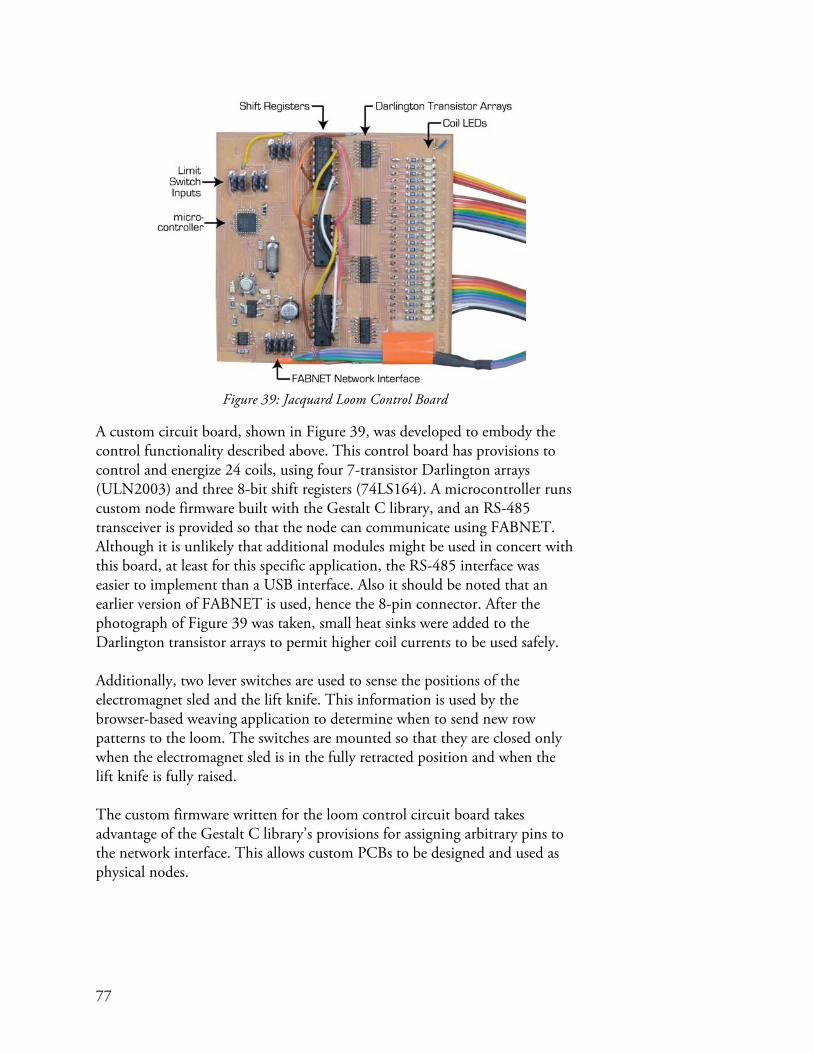
77
Figure 39: Jacquard Loom Control Board
A custom circuit board, shown in Figure 39, was developed to embody the control functionality described above. This control board has provisions to control and energize 24 coils, using four 7-transistor Darlington arrays (ULN2003) and three 8-bit shift registers (74LS164). A microcontroller runs custom node firmware built with the Gestalt C library, and an RS-485 transceiver is provided so that the node can communicate using FABNET. Although it is unlikely that additional modules might be used in concert with this board, at least for this specific application, the RS-485 interface was easier to implement than a USB interface. Also it should be noted that an earlier version of FABNET is used, hence the 8-pin connector. After the photograph of Figure 39 was taken, small heat sinks were added to the Darlington transistor arrays to permit higher coil currents to be used safely. Additionally, two lever switches are used to sense the positions of the electromagnet sled and the lift knife. This information is used by the browser-based weaving application to determine when to send new row patterns to the loom. The switches are mounted so that they are closed only when the electromagnet sled is in the fully retracted position and when the lift knife is fully raised. The custom firmware written for the loom control circuit board takes advantage of the Gestalt C library’s provisions for assigning arbitrary pins to the network interface. This allows custom PCBs to be designed and used as physical nodes.

78
Virtual Nodes
The loom virtual node is extremely simple. It has only two service routines: • shiftOutRequest() sends three bytes of data to the node where
they are shifted out on the shift registers, thus causing coils corresponding to high bits to energize.
• readSwitchesRequest() queries the status of the lift knife and electromagnet sled lever switches.
Figure 40 illustrates schematically the virtual and physical nodes for the Jacquard loom. It should be noted that because the control node is connected over FABNET, its virtual node is of the ‘Networked/Gestalt’ type.
Figure 40: Jacquard Loom Virtual/Physical Nodes
Virtual Machine
Figure 41: The Jacquard Loom Virtual Machine
The Jacquard loom virtual machine is mostly a wrapper for the virtual node. One important role taken by the virtual machine is in exposing the two key functions of the machine, sendPattern() and getLoomStatus(), over a remote procedure call interface. An HTTP interface was chosen so that the loom could be controlled by an interactive browser-based application.
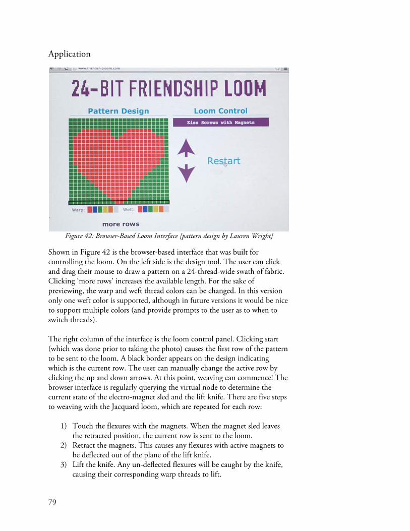
79
Application
Figure 42: Browser-Based Loom Interface [pattern design by Lauren Wright]
Shown in Figure 42 is the browser-based interface that was built for controlling the loom. On the left side is the design tool. The user can click and drag their mouse to draw a pattern on a 24-thread-wide swath of fabric. Clicking ‘more rows’ increases the available length. For the sake of previewing, the warp and weft thread colors can be changed. In this version only one weft color is supported, although in future versions it would be nice to support multiple colors (and provide prompts to the user as to when to switch threads). The right column of the interface is the loom control panel. Clicking start (which was done prior to taking the photo) causes the first row of the pattern to be sent to the loom. A black border appears on the design indicating which is the current row. The user can manually change the active row by clicking the up and down arrows. At this point, weaving can commence! The browser interface is regularly querying the virtual node to determine the current state of the electro-magnet sled and the lift knife. There are five steps to weaving with the Jacquard loom, which are repeated for each row:
1) Touch the flexures with the magnets. When the magnet sled leaves the retracted position, the current row is sent to the loom.
2) Retract the magnets. This causes any flexures with active magnets to be deflected out of the plane of the lift knife.
3) Lift the knife. Any un-deflected flexures will be caught by the knife, causing their corresponding warp threads to lift.

80
4) Pass the warp thread thru the resulting shed. 5) Lower the knife. This closes the shed and completes one cycle of
weaving. The browser-based interface is built using a combination of HTML, CSS, Javascript, and jQuery. Function calls are made on the virtual machine using AJAX requests, and return values (like the status of the switches) are encoded in a JSON response.
Results
Figure 43: A Pattern Woven Using the Jacquard Loom
The Gestalt C library was successfully used to interface with a microcontroller residing on a custom PCB. The computational operations needed to control the loom are extremely simple – just shifting out a few bytes – and the loom control firmware development benefitted from the structure imposed by the service routine approach. This was a case where writing custom communications code would have taken longer than writing the application itself. The design application took around a week to write, but largely because the author was learning JavaScript and jQuery in parallel with writing the application. Progress was significantly assisted by the many online forums on these topics. Interfacing with the loom’s remote procedure call interface from the application was not difficult because jQuery has good support for generating AJAX requests. The loom application has been tested successfully on Mac OS X and Linux using multiple web browsers. The only issue with the interactive application is the rate at which the loom’s state updates. There is a noticeable delay between when user changes the state of the loom and

81
when a new instruction appears in the application. This has on occasion also resulted in the user transiting between states faster than the browser could respond, thus causing the application’s state machine to become confused. The Jacquard loom was successfully used in conjuncture with the browser-based application to produce the swath of fabric shown in Figure 43.
Discussion and Conclusions
This case study confirmed that Gestalt can be easily used to rapidly build a control system for a somewhat unusual tool. The utility of Gestalt to this project was mostly one of communication. The Gestalt C library and virtual node base class provided an easy way of quickly talking to firmware running on the physical node. Additionally, the drop-in remote procedure call interface allowed immediate prototyping of the browser based application. A harder to quantify benefit of Gestalt was that it provided a language for thinking about how to control the machine. Having a set of templates to fill out avoided the feeling of staring at a blank screen, even if the task of coding the loom control from scratch using an Arduino and a Python script (sans Gestalt) would not have been too daunting. Perhaps the biggest lesson came from the development of the user interface and weaving application. Unlike most automated equipment, this loom is interactive, essentially melding human effort with automation. One of the nice things about the browser interface was that instructions for the use of the machine could be easily displayed in context as the loom was being used. One could imagine a way of likewise capturing user techniques at various steps and tagging them to particular actions of the machine. For example, techniques for packing the rows of thread or maintaining tension could be shown only when relevant. Because the interface is browser-based, and indeed served from a 3rd party website (in the example, the website www.friendshiploom.com), such crowd-driven features becomes possible. The issue of latency in the browser-based application reflecting the state of the loom is easily fixable by updating the rate at which the loom is polled, but brings to light one of the shortcomings of the current Gestalt communications scheme. Because the model between virtual and physical nodes is one of master-slave, call-and-response, the application must constantly be polling the loom. It would be much more efficient for the loom to push its state to the browser. There is functionality for this built into Gestalt, but issues of bus contention for networked nodes would need to be resolved.


83
An Automated Coil Winder
Introduction
One of the major challenges involved in building a personal Jacquard loom was creating electromagnets with consistent resistances. The author’s first attempt at winding the coils for the electromagnets tediously involved a hand drill and yielded results which were inconsistent and ugly. The ugliness was not a big issue, but inconsistent coils meant that the maximum coil current was limited by the coil with the lowest resistance. These low-resistance coils would draw a disproportionate amount of current and overheat at a voltage well below what was ideal for the higher-resistance coils. To solve this problem, a coil winder was built, and controlled using the Gestalt framework. This case study addresses the use of Gestalt to automate a specific task facing a user – needing to wind 24 coils precisely – by building a quick-and-dirty machine, and discusses more generally the crossover point at which it makes sense to automate rather than perform by hand. The use of an Arduino and a generic stepper driver ‘shield’ further builds on the utility of pre-existing nodes to save time in development. Additionally, the Gestalt kinematics library demonstrates the control of a machine using radial rather than Cartesian coordinates. In a way, this project is the ideal case-study for the utility of Gestalt. A hard-to-come-by tool was needed to automate an otherwise tedious manual task,

84
and a working prototype was developed within a couple of days. This is precisely the use-case that Gestalt was created for – to enable individuals to rapidly build their own tools to satisfy a fabrication need. A good analogy might be a person tasked with removing the spaces from the filenames of multiple files sitting in a directory. They could manually remove the spaces themselves, or they could write a quick script to do the work for them. There is a cross-over point at which writing a program takes less time than performing the work by hand. The goal of Gestalt is to pull closer the cross-over point of when it makes sense to build a tool rather than do something the hard way. The coil winder was originally controlled by older hardware and a prior version of Gestalt that didn’t support the RPC-HTTP interface. Since then, better hardware and a browser-based application for the coil winder have been developed. This presentation of the coil winder will demonstrate it in conjuncture with the new hardware and control application.
Hardware
Figure 44: Coil Winder Mechanical Schematic
Mechanically, the coil winder is built as shown in Figure 44. The core of the electromagnet to be wound is held in a chuck and is spun by the spindle stepper motor. A carriage, through which passes magnet wire from a spool, is moved back and forth in synchrony with the rotation of the spindle. This causes wire to be neatly wrapped in a helical coil onto the electromagnet core.

85
Figure 45: Coil Winder Real Hardware
Figure 45 shows the actual hardware represented by the schematic of Figure 44.
Figure 46: A Stepper Driver Arduino Shield
After discovering the ease of creating nodes using an Arduino and the Gestalt C library while building the tape printer, a generic stepper driver shield was built to further explore the use of the Arduino platform coupled with Gestalt in prototyping new machines. Shields are add-on modules that plug on top of the Arduino, thus expanding its capabilities. Stepper motors are a common element in many tools, and indeed many tools, like the coil winder, require three or fewer stepper motors. To satisfy the needs of the widest range of machines, the shield also has an H-bridge for driving a stepper motor, and a servo output for controlling hobby RC servos. The combination of three stepper drivers, an H-bridge, and a servo port make the shield suitable for many projects including CNC mills. In ways, the concept of a shield goes against the modular principles of Gestalt, where each electromechanical

86
component has its own networked control node. However, the shield has proven itself useful for rapid prototyping several machines including a large-format drawing machine currently in development. One additional feature that makes the stepper shield well-suited to a rapid prototyping role is that the current limits on each stepper driver can be set in software. Current limiting is important to achieve maximum performance from a stepper motor, and the value of the current limit is highly dependent on the motor being used. Typically the process of setting the motor current involves calculations to determine the proper reference voltage for a given current, and then turning potentiometers while looking at a multi-meter to set the right reference voltage. Current limits are set by calling a function on the virtual node and providing as arguments the desired current, in amperes, for each motor.
Virtual Nodes
Figure 47: Coil Winder Virtual / Physical Node
The coil winder is controlled by an Arduino with a triple-stepper driver shield which connects to its matching virtual node over the USB interface provided by the Arduino. The node supports a number of relevant service routines, listed below:
• setReferenceVoltage() sets the voltage reference for the current limiting circuitry on each of the shield’s stepper drivers. A wrapper function setMotorCurrents() accepts desired motor currents as arguments and handles the conversion between desired current and reference voltage.
• spin() causes the stepper motors to take the requested number of steps. If a step command is currently being executed when this function is called, the move is queued by the physical node. If the queue is full, the service routine waits for a vacancy before returning. This service routine is discussed in much greater detail within the context of the following case study on the development of a portable multi-purpose fabrication machine.
• spinStatus() queries the current status of the stepping algorithm, including the current step position and the number of vacant slots in

87
the buffer. If the buffer is full, spinStatus() is used by the spin() service routine to wait for a vacancy.
• disableMotors() de-energizes all stepper motors. This may be called so that the machine can be jogged by hand, and also to prevent the motors and/or drivers from getting hot while idle. Of course, once the motor drivers have been disabled, the position of the machine is no longer known. It should be noted that there is no enableMotors() service routine. This is because the motors are automatically enabled whenever a spin command is received and before motion commences.
Virtual Machine
Figure 48: Coil Winder Virtual Machine
Figure 49: Coil Winder Kinematics
The virtual node sees the world in terms of steps. It has no conception of the mechanisms to which its motors are attached. One of the roles of the virtual machine is to assist in translating between machine coordinates and motor coordinates. To this end, the coil winder virtual machine (shown in Figure 48) incorporates a few elements which have not yet been demonstrated in the prior case studies. A position object keeps track of machine’s position in units of revolutions for the spindle and millimeters for the carriage. Figure 49 shows the way in which these units are converted into steps. Each axis is assigned a chain of mechanical elements which transform motion from one

88
set of units to another. For example, the carriage translates linear position (in mm) thru a pulley into revolutions, and then thru a stepper motor into steps. A similar transformation is done to the spindle rotation to convert between revolutions and steps. An additional block at the end of each chain converts steps into microsteps. Many stepper motor drivers perform microstepping, meaning that they are able to control the relative currents in each phase of the stepper motor in an attempt to interpolate the position of the motor’s rotor. Microstepping has two advantages: it allows for higher positioning resolution, and it smooths the motion of the stepper motor at slow speeds. The stepper drivers used by the triple stepper shield perform 1/16 stepping. However, the physical node accepts step commands in units of ¼ steps, and multiplies the commands by a factor of 4 once they are received to convert to units of 1/16 steps. This is done to achieve smooth motion at slow speeds, while admitting that the positional interpolation is likely not accurate beyond ¼ steps. The final task in calculating the number of steps to take on each motor is to pass the results of the mechanical chains thru a transformation matrix. In the case of the coil winder the matrix is an identity matrix and has no effect. However, the upcoming case study will demonstrate an occasion when this transformation matrix is useful. The move() function within the virtual machine accepts movement commands in machine units (mm and rev), and, using the kinematics just described, calculates the number of steps required to perform that move. The move function then passes these step values to the virtual node’s spin() function to cause the motion to occur on the real machine. There is additionally a jog() function which accepts relative positions rather than absolute machine positions. This is can be useful to an application which provides the user with jog buttons.

89
Application
Figure 50: Browser-Based Coil Winding Application
A browser-based application was made to control the coil winder. The user enters a few parameters describing the coil they want to wind, like the wire diameter, length of the coil, and number of wraps. From these parameters, the application can calculate the pitch of the wire helix and thus can generate move commands that it calls on the coil winder’s virtual machine via a remote procedure call interface. Buttons are provided for jogging the machine, as well as beginning the coil winding operation in either direction. An ‘off’ button will cut power to the motors so that the machine can be manipulated manually. Finally, a digital readout and corresponding ‘zero’ buttons allow the user to both know the position of the machine and set its origin.

90
Results
Figure 51: An array of electromagnets for a personal Jacquard loom, wound by hand.
Figure 52: An array of electromagnets wound using the coil winder.
The coil winder was indeed able to produce electromagnets that were far more consistent (and slightly better looking) than those wound by hand. Figure 51 shows an array of electromagnets that were wound by hand using a power drill. Notice that the diameters of the hand-wound coils are not only inconsistent, but the shape is asymmetrical. The same coils were re-wound using the coil winder with far better results as shown in Figure 52. The overall variation in resistance of the hand-wound coils was around 10%, whereas the variation of the machine-wound coils was only a few percent. Winding coils by hand took on average about 10 minutes per coil because frequently the coil would need to be restarted to correct gross errors. The coil-winding machine was able to wind a coil in 3 minutes (including loading and unloading). Over the course of 24 coils, the total time savings of using the machine was therefore just under 3 hours. It took roughly two full days to design and build the coil winder; this included predominantly constructing the mechanical hardware, and also the time needed to build a virtual machine using Gestalt. Indeed, building the virtual machine controller for the coil winder was nearly trivial. Pre-existing stepper controllers and their

91
virtual nodes were utilized, meaning that all that needed to be written was the kinematics describing the spindle and carriage mechanical chains. The cross-over point where it would have made sense to build the coil winder – strictly from a time-savings perspective and ignoring quality differences – would be at around 140 coils. This assumes that the coil winder saves 7 minutes per coil, but does not take into account any improvements in manual technique and the resulting increase in efficiency which would almost certainly develop over the course of winding 140 coils.
Figure 53: An electromagnet for a personal Jacquard loom wound using the coil winder.
Figure 54: A more typical output from the coil winder.
Figure 53 shows one of the best coils wound by the coil winder. Producing coils this consistent was atypical, however. A more usual result is shown in Figure 54. While the windings of this latter coil are not perfectly placed, the coil is still symmetric (which cannot be said for the hand-wound coils). There appears to be a cumulative effect to any errors in wire placement; a small

92
mistake made early on can make the difference between a perfect coil like in Figure 53 and an OK coil like in Figure 54. Potential sources of error include the motion of the machine being slightly different than the ideal pitch of the coil, incorrect tension in the wire (which is presently uncontrolled), and an incorrect estimation of the coil length.
Discussion and Conclusions
The value proposition of the coil winder is both its ability to produce coils that are more consistent than what could be produced by hand, and also to increase the speed of the process. It is tough to evaluate whether it made sense or not to build the coil winder for the specific situation outlined here because the time needed to hand-wind coils of equal quality is unknown. However it has become clear that with the use of a controls framework like Gestalt, the time needed to build even simple tools such as this coil winder is disproportionately biased towards the mechanical hardware. This suggests that in order to fully achieve the initial goal of Gestalt, which is to enable individuals to rapidly built their own automated tools, perhaps a mechanical framework for rapid development is now needed. The use of a pre-built Arduino shield – essentially a daughterboard for the Arduino – made control of the coil winder strictly a programming exercise. This is in contrast with the tape printer case study where as much time was spent wiring as developing the control system. In that example, there was no shield available that contained all of the functionality needed for the tape printer. While pre-built shields clearly save time, they can also be restrictive. It is for this reason that Gestalt is designed to support control of multiple modular nodes across a network, which is explored in the case study ‘Distributed Control of a Fabrication Machine’.
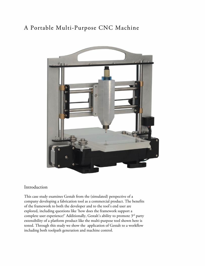
A Portable Multi-Purpose CNC Machine
Introduction
This case study examines Gestalt from the (simulated) perspective of a company developing a fabrication tool as a commercial product. The benefits of the framework to both the developer and to the tool’s end user are explored, including questions like ‘how does the framework support a complete user experience?’ Additionally, Gestalt’s ability to promote 3rd party extensibility of a platform product like the multi-purpose tool shown here is tested. Through this study we show the application of Gestalt to a workflow including both toolpath generation and machine control.

94
In order to explore these topics we have developed a portable automated XYZ motion platform that accepts interchangeable toolheads to perform a wide variety of tasks. Philosophically, this machine is much closer to being a product than those presented in the prior case studies. Its design is based around a novel machine configuration which makes efficient use of materials and is easily producible. A custom circuit board was designed that is specifically tailored to the machine’s form factor, and includes all of the functionality needed to control the various electro-mechanical elements of the machine such as stepper motors and external toolheads. Within the context of the development of Gestalt, this machine serves two purposes. The first is that it has been a perfect platform on which to develop much of Gestalt’s Cartesian motion functionality, including a look-ahead path planning algorithm. Additionally, this machine helps answer the question of whether a flexible framework like Gestalt – originally intended for the rapid prototyping of machines – is also suitable for use in a commercial product. This question is important because it would be beneficial if the same framework used to prototype new machines could provide continuity thru their transition into production. To explore both this and questions regarding user experience, a complete browser-based application was developed for producing circuit boards using the machine.

95
Figure 55: PCB Mill (2008)
Figure 56: MTM Multifab (2010)
Figure 57: PopFab (2012)
Figure 58: PopFab Vinyl Cutter
Figure 59: PopFab Milling Spindle
Figure 60: PopFab 3D Printer
The machine presented here is the latest point along a trajectory which started with the author’s senior thesis in 2008, where they built the small mill shown in Figure 55 for routing circuit boards. The realization soon came that many fabrication tools, such as milling machines, 3D printers, and laser cutters, all have similar XYZ kinematics. This lead to the development of the MTM Multifab (Figure 56) with Maxim Lobovsky in 2010 as part of the MIT Center for Bits and Atoms (CBA) Machines That Make project. The Multifab is a multi-purpose XYZ positioner that accepts a variety of different toolheads including a vinyl cutting knife attachment, a spindle for milling, and a 3D print head. Subsequent work was conducted with Nadya Peek of the MIT CBA to apply the multi-tool philosophy of the Multifab to a portable machine. The result, shown in Figure 57, is a briefcase multi-purpose personal fabricator called PopFab. A variety of the Multifab toolheads were rebuilt for the PopFab. These are shown in Figure 58, Figure 59, and Figure 60. In the tradition of naming machines, the portable automated multi-tool described by this case study is called the Magic Mill. The name is a bit misleading, since the tool is capable of more than just milling.
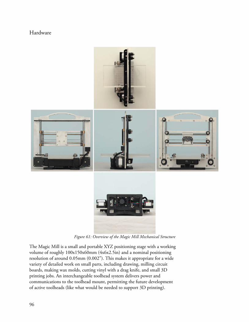
96
Hardware
Figure 61: Overview of the Magic Mill Mechanical Structure
The Magic Mill is a small and portable XYZ positioning stage with a working volume of roughly 100x150x60mm (4x6x2.5in) and a nominal positioning resolution of around 0.05mm (0.002”). This makes it appropriate for a wide variety of detailed work on small parts, including drawing, milling circuit boards, making wax molds, cutting vinyl with a drag knife, and small 3D printing jobs. An interchangeable toolhead system delivers power and communications to the toolhead mount, permitting the future development of active toolheads (like what would be needed to support 3D printing).

97
Figure 62: Magic Mill Kinematics
The Magic Mill has somewhat unconventional kinematics that are shown schematically in Figure 62. The X and Z are serially stacked in the sense that the X axis rides on the Z axis. The Y axis is a removable pallet.
Figure 63: H-Bot Kinematics
The X and the Z axis are controlled by two stationary motors mounted in the XZ plane. A timing belt wraps around a series of 8 pulleys in a configuration known as an H-bot (Sollmann, Jouaneh, & Lavender, 2010).The rotation of motors A and B in Figure 63 are coupled together through the belt to result in X and Y motion. This type of drive might be termed a differential drive. The sum of the motor rotations results in X axis motion, and the difference
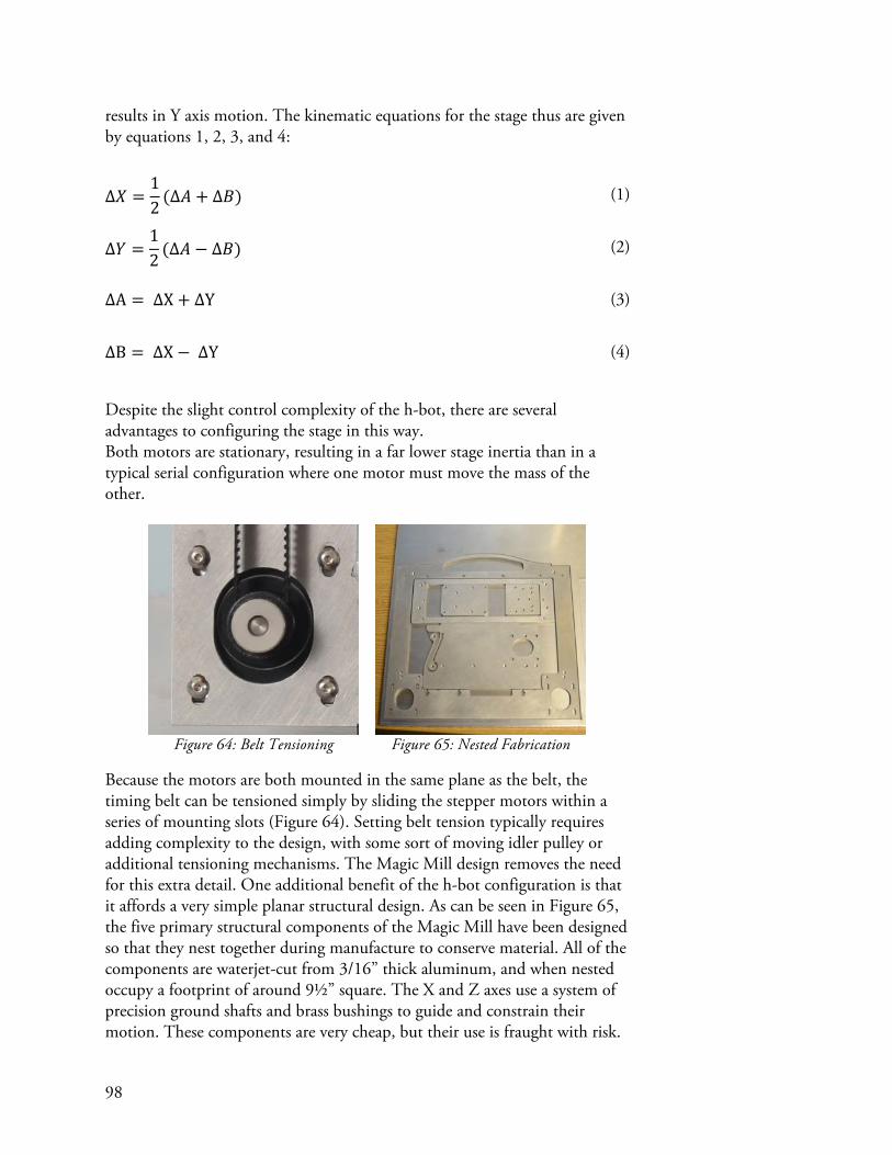
98
results in Y axis motion. The kinematic equations for the stage thus are given by equations 1, 2, 3, and 4:
Δ𝑋 =12 (Δ𝐴 + Δ𝐵)
(1)
Δ𝑌 =12 (Δ𝐴 − Δ𝐵)
(2)
ΔA = ΔX+ ΔY (3)
ΔB = ΔX− ΔY (4)
Despite the slight control complexity of the h-bot, there are several advantages to configuring the stage in this way. Both motors are stationary, resulting in a far lower stage inertia than in a typical serial configuration where one motor must move the mass of the other.
Figure 64: Belt Tensioning
Figure 65: Nested Fabrication
Because the motors are both mounted in the same plane as the belt, the timing belt can be tensioned simply by sliding the stepper motors within a series of mounting slots (Figure 64). Setting belt tension typically requires adding complexity to the design, with some sort of moving idler pulley or additional tensioning mechanisms. The Magic Mill design removes the need for this extra detail. One additional benefit of the h-bot configuration is that it affords a very simple planar structural design. As can be seen in Figure 65, the five primary structural components of the Magic Mill have been designed so that they nest together during manufacture to conserve material. All of the components are waterjet-cut from 3/16” thick aluminum, and when nested occupy a footprint of around 9½” square. The X and Z axes use a system of precision ground shafts and brass bushings to guide and constrain their motion. These components are very cheap, but their use is fraught with risk.

99
Binding of the sliding carriage will occur if the distance between the bushings is not exactly the same as the distance between the shafts. A similar outcome results if the guide shafts are slightly misaligned relative to each other, because the distance between the shafts thus changes with the position of the carriage. One solution is for some of the bushings to be given compliance so that they can adapt to the distance between the shafts. This approach solves the manufacturing problem of mounting the bushings with exactly the same separation as the shafts, and also accommodates misalignment of the shafts. However, adding compliance to the bushings poses challenges of its own and adds complexity to the design of the axis. The solution to the problem of alignment adopted by the Magic Mill is simple. The two guide shafts of each axis are held parallel to each other by laser-cut yokes – one at each end – which also fix the shafts to the aluminum frame of the machine (Figure 66).
Figure 66: Schematic of X and Z Axis Guide System
Figure 67: A set of yokes keeps the guide
shafts parallel.
Figure 68: Bushings are epoxied to the
sliding plates.
It turns out that the laser cutter (or at least the two tested, both produced by Universal Laser Systems) produces repeatable enough yokes (Figure 67) that the shafts are held within the necessary tolerances of the strategy. In order to set the distances of the brass bushings to be exactly the same as the shafts, an

100
approach is borrowed from David Carr’s MTM Mantis (Carr, 2010): the axis is assembled, and the bushings are epoxied to the carriage. This has the effect of copying the separation of the shafts to the bushings, rather than trying to set both independently and hope that they are nearly identical. Time will tell whether the epoxy used, Loctite E-120HP, has both the strength and durability desired for this application. Several stages have been built using this technique and have logged many hours of use each without a single failure. Figure 68 shows an epoxy joint on one of the Z axis bushings. In typical desktop-sized tools, the user needs to fixture their material within the confined quarters of the machine’s frame. Perhaps more problematic is that when material needs to be removed post-fabrication, it is not uncommon for damage to occur. The author has observed on several occasions end-mills being broken because the user lifted up too forcefully on a milled circuit board that is taped down to the table of a machine, causing the tape to suddenly release and send the finished board flying into the delicate tool. The Y axis of the Magic Mill is removable, which facilitates the fixturing and defixturing of material outside the machine and also makes the machine more compact when in storage or during transportation.
Figure 69: Removable Pallet
Figure 70: Pallet Preload Mechanism
The pallet, shown in Figure 69, is currently constructed of acrylic with a laser-cut grid pattern on its undersurface. The pallet is guided by four V-rollers, two on each side. Corresponding V-grooves are machined into the sides of the pallet. The rollers on one side are mounted on flexures (Figure 70) which preloads the pallet against the fixed rollers on the opposite side. Controlled motion of the pallet in the Y axis is provided by a rack potted into the pallet and a pinion gear mounted to a stepper motor on the machine. There are a few remaining issues with the Y axis drive system. There is a slight amount of backlash in the rack and pinion interface. Additionally, the contact force of the gears counteracts some of the preloading of the stage.

101
The compliance built into two of the rollers and the asymmetric location of the rack and pinion raise concerns for 3D printing, where large inertial forces may cause the Y axis to skew. Another concern is that acrylic is not a good material choice for the pallet because of the high contact pressures at the V rollers. If this machine is ever mass-produced, it would make sense to use a harder and tougher material such as aluminum.
Figure 71: The Magic Mill Control PCB
A custom circuit board was developed for the Magic Mill than incorporates circuitry for the control of three stepper motors, an RC servo, and an arbitrary switchable load such as a DC motor. The machine interfaces with the computer, and thus its virtual machine, over a USB port. Power is supplied through a 2.5mm barrel jack. Currently a 24V power supply is being used. Additionally, a FABNET port enables additional nodes to extend the control system. The FABNET header on the PCB is brought up to a connector on the front of the machine where it can be connected to by active toolheads. A set of digital potentiometers allows the current limits to be set in software for each of the stepper motors. Generally this is useful for quickly supporting a wide variety of motors as might be encountered in a machine prototyping situation (as demonstrated on the control board described in the coil winder case study). The intended use for the Magic Mill, however, is for

102
homing. Rather than using limit switches to home the machine, the motor currents can be reduced and the X and Z axes can be brought against the limits of their travel. This homing approach has yet to be tested.
Figure 72: Magic Mill PCB Mounted to
the Y Axis Guide Mount Plate
Figure 73: The XZ Stage
Figure 74: Wiring Up the Motors
Figure 75: Electronics Housing
The control board for the machine is mounted upside-down on the undersurface of the Y axis guide mount plate as in Figure 72. This assembly is then mounted to the XZ stage (Figure 73), and the motors are connected to the control board (Figure 74). The 3D printed enclosure of Figure 75 then enshrouds the electronics. One of the nice features of the machine’s mechanical architecture is that not only are all of the motors stationary, but they all reside at the bottom of the machine. This makes it very easy to route their wiring. Because the PCB is mounted upside down, a fan is provided to increase convective heat transfer off of the stepper driver ICs’ heatsinks.

103
Figure 76: Power and USB Connections
Power and USB connections are made on the back of the machine, as shown in Figure 76.
Figure 77: Drawing Tool Head
Figure 78: Milling Spindle
Figure 79: Spindle Attachment to
the FABNET Port
To date, two tool heads have been developed for the Magic Mill. The pen attachment in Figure 77 is useful for drawing pictures, besides being handy for debugging control code. A high speed spindle has also been built (Figure 78), based on an earlier design by the author. Figure 79 shows how the spindle attaches to the accessory FABNET port on the side of the machine. Power to the FABNET port is currently wired thru the PWM output on the Magic Mill PCB, and a MOSFET on this board currently controls the spindle. Eventually the spindle could have its own dedicated PCB controlled as an additional Gestalt node over the FABNET interface. Unfortunately, despite weeks of concentrated debugging, the spindle is still not functional. There is an electrical issue which causes the microcontroller to freeze, reset, and occasionally have its memory wiped when the spindle turns on. The problem has been isolated to electrical noise, and a rerouted PCB is currently in the works which does a better job of isolating the spindle ground from the microcontroller ground. Perhaps putting the spindle intelligence and control on the tool head would fix this problem.

104
Figure 80: And It Travels...
Finally, some effort has been put into exploring how easily the machine travels. Figure 80 shows that the Magic Mill stores comfortably with its power supply and USB cable inside an HPRC 2400F hard case.
Virtual Nodes
Because all of the functionality of the Magic Mill’s control system is co-located on one PCB, it is represented by a single virtual node.
Figure 81: Magic Mill Virtual Node
The service routines of the Magic Mill virtual node are almost identical to those of the coil winder described in the previous case study. The descriptions of the Magic Mill virtual node’s service routines are listed here:
• setReferenceVoltage() sets the voltage reference for the current limiting circuitry on each of the control board’s stepper drivers. A

105
wrapper function setMotorCurrents() accepts desired motor currents as arguments and handles the conversion between desired current and reference voltage.
• spin() causes the stepper motors to take the requested number of steps. If a step command is currently being executed when this function is called, the move is queued by the physical node. If the queue is full, the service routine waits for a vacancy before returning.
• spinStatus() queries the current status of the stepping algorithm, including the current step position and the number of vacant slots in the buffer. If the buffer is full, spinStatus() is used by the spin() service routine to wait for a vacancy.
• disableMotors() de-energizes all stepper motors. This may be called so that the machine can be jogged by hand, and also to prevent the motors and/or drivers from getting hot while idle. Of course, once the motor drivers have been disabled, the position of the machine is no longer known. It should be noted that there is no enableMotors() service routine. This is because the motors are automatically enabled whenever a spin command is received and before motion commences.
• pwmRequest() accepts a value ranging from 0 to 1, and sets the physical node’s PWM output to this value scaled by a factor of 255. This service routine is used by the virtual machine to turn on and off the spindle.
The spin() service routine is perhaps the most complex of the service routines yet written. It is used to command the physical machine to take steps, and also controls the velocity of the resulting moves. Table 2 shows the packet format that spin() uses to communicate between the virtual and physical nodes.
Table 2: Spin() Packet Format
Spin() uses a variant of the Bresenham line drawing algorithm, discussed in detail in Appendix A, to synchronize the three stepper motors. It should be noted that only one byte is allocated to represent the number of steps to take

106
in each axis. This helps to reduce the size of the packet at the cost of needing to send multiple packets to represent longer moves. However, because network bandwidth is only an issue for brief moves consisting of few steps, it makes sense to reduce the packet size so that packet transmission is optimized for the bandwidth-limiting case of short moves. The last three bytes of the packet are dedicated to setting the profile of the stepping speed. The stepping speed is not set directly. Rather, it is set by providing an acceleration rate and a number of steps over which to accelerate or decelerate.
Figure 82: Spin() Velocity Profile
Figure 82 illustrates how the acceleration rate is integrated over the course of a given number of steps to control the stepping speed. It is important for high-speed motion that the step generator is able to accelerate and decelerate the machine rather than starting full-tilt. A path planner is built into the virtual machine’s move function, which decomposes velocity profiles into the format described above. This representation of velocity was chosen because it both minimizes the difficulty of, and hence compute time to perform, the acceleration calculations on the physical node. Additionally it minimizes the packet size. This approach has drawbacks, however. One is that not all requested velocities can be achieved, because the velocity is parameterized non-linearly in terms of number of steps (which is a discrete quantity). There is also the risk of velocity drift because of rounding errors either in the physical node or in the path planner. Finally, there is a lock-up condition which can happen upon deceleration. If the velocity hits zero before the last step is taken, the node becomes unable to complete the current move and becomes frozen. Several solutions to this last problem are possible, including:
• Never operating at a zero stepping velocity. Acceleration can begin from and end at a greater-than-zero minimum speed, which is feasible so long as the stepper motor can accelerate to the minimum speed over the course of a single step.
• Detect the lock-up condition in the physical node and continue stepping at a pre-set minimum speed before dropping the velocity to zero after the move is over.

107
The acceleration algorithm is still being optimized and debugged as of this writing but is functional. Unfortunately, round-trip latency between the physical and virtual nodes prevents the machine from operating at a speed commensurate to the utility of using an acceleration profile.
Virtual Machine
Figure 83: Magic Mill Virtual Machine
The Magic Mill virtual machine, shown schematically in Figure 83, contains the control board’s virtual node, a position state object, kinematics for transforming between motor units of microsteps (as used by the spin object) to millimeters and back, remote procedure call interfaces for receiving commands both over HTTP and as a file, and several machine-level functions. The position state object is used for storing the current position of the machine, and is modified by the move() function. However it should be noted that because motion commands are queued at both the virtual machine and the physical node, the position object’s value typically leads the actual position of the machine. For this reason, the position object has two parameters: ‘future’ and ‘current’. ‘Future’ stores the pending position of the machine once all of the queued moves have been processed, and ‘current’ is intended to store the estimated position of the machine. However this feature has not yet been fully implemented.

108
Figure 84: Magic Mill Kinematics
The kinematics of the Magic Mill are depicted in Figure 84. Each motor has a mechanical chain which starts as microsteps at the virtual node, are converted to steps at the motor driver, then revolutions by the motor, and finally millimeters by either the pulley or rack and pinion. It should be noted that the first mechanical element chain in Figure 84 drives the Y axis, but a ‘pulley’ element is used rather than a gear. Pulleys are mathematically identical to the rack and pinion drive in that they transform from rotation to translation, whereas the gear element in the Gestalt mechanics library only scales rotations. A kinematics matrix is then used to transform linear displacement at the motors into motion of the machine, according to the equations given for the h-bot kinematics in the introduction to this case study. This final kinematics matrix for the machine is a compound matrix formed by placing a 1x1 identity matrix on a diagonal with the 2x2 h-bot matrix. Finally, a ‘routing’ element is used to handle the sticky situation that the B and C motors drive the non-adjacent (in matrix space) X and Z axes. One 3x3 matrix could have been substituted for the two kinematics matrices and the routing element, but then modularity would have been lost because each 3-axis machine which uses an h-bot would need to write their own transformation matrices. A number of machine-level functions are included, which provide the user application with the necessary interface to control the machine. Functions like getPosition() and setPosition() are used by the application to display the current machine position and to zero the tool. setSpindleSpeed() is used to turn on and off the motor, but due to the noise issues previously discussed, this function has gotten little use as of late. The most complex of the functions is move(). Move() takes parameters including the requested absolute machine position and a desired velocity. A move object is consequently generated, which is fed into a look-ahead path planner to calculate a suitable acceleration and deceleration profile for the machine. The

109
path planner queues up to 50 moves in a first in-first-out buffer; each time a new move is received, the planner looks at all of the pending moves and attempts to accelerate the machine to the desired speed under maximum acceleration constraints. For example, if a series of short, nearly collinear moves terminate in a sharp change of direction followed by additional moves, the path planner might begin decelerating many moves before the corner is hit, so that the sudden change in direction does not overload the motors. The jog() function simply wraps the move function to provide relative positioning, which is useful for applications which have jog buttons. The final element of the virtual machine is the remote procedure call (RPC) interface. Both an HTTP interface is provided for interactive control of the machine via a browser based app, and a file-based interface is provided for processing long motion paths. To restate other parts of this document, the RPC-over-HTTP converts an HTTP request into a function call, and issues a response containing the return values of those function calls in the form of a JSON dictionary. The RPC-as-a-file interface accepts a text file containing a long list of function calls, and sequentially makes those function calls on the virtual machine. This method is superior to the RPC-over-HTTP interface for generating long chains of commands, as is common when executing a toolpath on the machine. Both interfaces are used by the PCB milling application, which was developed for this case study, to provide interactive and scripted control of the machine.

110
Application
Figure 85: Screenshot of Browser-Based PCB Milling Application
Magic Mill is intended to simulate a commercial product. One use case that was explored is the idea that someone might control their tool from a website developed by a 3rd party. This makes particular sense for a multi-purpose tool that can assume many different uses depending on which toolhead is attached. Within the context of PCB milling, the 3rd party source of the application might be the toolhead developer, or perhaps someone who sells PCB making materials, or maybe a board house that wants to convert tool users into customers when it comes time to place production orders. The idea of controlling a tool from within a web browser originated in conversations that the author had had with Ed Baafi, the founder of ModKit (Modkit, 2013). ModKit is a browser-based programming application for the Arduino platform. A small ‘widget’ runs on the user’s computer and allows the

111
browser-based application to talk to and program the Arduino. Ed and the author discussed the idea of applying the same concept to tools. A PCB milling application has been developed for the Magic Mill that handles the entire process of converting board artwork into toolpaths and then running these toolpaths on the machine. Additionally, the application features a control panel for the machine that enables tasks like jogging and zeroing the tool. A screenshot of the PCB milling application is shown in Figure 85. Like the Jacquard weaving application shown in a prior case study, the screen is divided into two sections: toolpath generation is on the left, and interactive machine control is on the right.
Figure 86: Uploading Board Artwork
Figure 87: Generating a Toolpath
Toolpath generation begins when the user drags an image of their board artwork (only the PNG format is currently supported) into the toolpathing pane, shown in Figure 86. Cutting parameters are then set, including tool

112
diameter, how deep to cut, how far to retract, and a variety of speed parameters. A drop-down menu allows the user to select whether they want to download a G-code file, or to run the toolpath directly from the browser. When the ‘generate’ button is pressed, the image, along with all of the user-provided parameters, are sent to a server. The server then runs Prof. Neil Gershenfeld’s Fab Modules (Gershenfeld & MIT-CBA, 2013) to convert the PNG into a vectorized RML file. RML is a format very closely related to the plotter language HPGL that is used by the Roland line of desktop milling machines. This process is performed twice; the first time is done with no tool offset, and the second time with the user-supplied tool offset. If a different number of contours is rendered by both iterations, the user is notified that some paths have been lost in the tool offsetting process. Software written by this author then reorders the contours around PCB traces to minimize traverse lengths. This is done because as of the time of this writing, the fab modules output contours in a highly non-optimal order. Finally, the reordered paths are written as a file. If G-code has been selected, the paths are encoded in the standard G-code format. If ‘Run’ has been selected, the toolpaths are compiled into a list of function calls to be made on the virtual machine. A number of statistics including path envelope and estimated cutting time are provided. A link is also provided at the bottom to allow the user to download the generated file.
Figure 88: Running a Toolpath
Once the toolpath generation process is complete, and if the user selected ‘run’ in the drop-down menu, a ‘toolpath execution’ button appears as in Figure 88. The user then jogs the machine until the tool is at the desired origin (typically the lower left corner of the artwork) and then zeros the tool

113
by clicking on the ‘zero’ buttons next to each axis. Finally, the user clicks the ‘run!’ button to begin milling the PCB. Pressing this button sends a command to the virtual machine that instructs it to request the just-generated toolpath RPC file from the server. From here on out the RPC-as-a-file interface kicks in, and sequentially reads and executes function calls from the RPC file.
Results
Figure 89: Using the Magic Mill
Figure 90: Output using PCB Milling Application

114
The complete workflow of a browser-based PCB milling application controlling the Magic Mill using a virtual machine was successfully tested in the setup shown in Figure 89, albeit with a pen attachment instead of a machining spindle. Figure 90 shows the output generated by this tool chain from PCB artwork provided as an input. The development of the Magic Mill was conducted in a manner similar to that of a commercial product. The mechanical design was defined entirely using CAD and then manufactured using computer controlled tools. A custom PCB was designed in tandem with the mechanical system, ensuring that they fit together properly and that cable routing would be efficient and unobtrusive. Gestalt’s role in the development of the machine came into play once the PCB had been designed and firmware development commenced. As in the other case studies, the ability to write firmware within a communications framework made it possible to begin testing almost immediately. Also, the modular, layered structure of Gestalt enabled application development to be conducted concurrently with firmware and virtual machine development. This is because each layer of abstraction is independent from the other layers, and possesses known interfaces. From the perspective of the user (played by the author), the ability to control the machine from the developed browser-based application is currently on par with other machines that use native applications. Just as with these alternatives, the browser interface requires that software is installed on the user’s computer; in this case, the user must install the Python-based virtual machine with which the browser communicates. However because Python is platform-independent, the virtual machine does not need to be modified to support different operating systems.
Discussion and Conclusions
Much of the benefit of using Gestalt within a commercial context is derived from its modular nature. Gestalt’s enforced modularity shows promise of benefitting the development of a commercial product because it enables individual components to be built and tested independently. This property is anticipated to be useful for the development of tools built not by individuals but by teams. Additionally, the abstraction afforded by Gestalt makes it possible to embed all process knowledge within the application, rather than the tool. This means that the virtual machine has no concept of what the tool is being used for, only of what capabilities in terms of sensing and actuation that the tool affords. The result is that 3rd parties can easily develop new applications for the tool. For example, one could easily see the Magic Mill being outfitted with a USB microscope and used to take large stitched

115
pictures, or being used as an optical comparator to take distance measurements. The browser-based interface plays a significant role in enabling the extensibility of the tool. A toolhead developer can simply publish their application on their own server as a webpage, which the tool user can visit to take advantage of the functionality. This approach is nice because the user doesn’t need to install new software to control their tool. By providing a virtual machine interface to their tool, manufacturers can foster the growth of an ecosystem of new and unexpected applications. An additional benefit of the browser-based interface for the tool user is the possibility of database-driven applications. An example might be a website that offers a repository of PCB designs accompanied side-by-side with machine control. This promises a complete user experience currently lacking in automated tools. Standard practice today is that the generation and storage of design files is completely isolated from the tools used to bring them into reality. There are as-of-yet unexplored security issues involved in giving web sites control of a local tool. While the remote procedure call interface only permits explicitly allowed functions to be called on the machine, there is inherent risk in permitting a website to execute functions on a user’s machines – both their computers and their fabrication tools. One final observation is on how the end user relates to the tool. Unlike automated tools that embed most of their logic within firmware, the virtual machine approach gives users the opportunity to dissect the control system of their machine just as they might take apart its hardware. This makes the machine accessible to them for purposes of modification, education, and also perhaps just becoming more intimately aware of how it works. Additionally, if the same accessible framework is used to build both commercial and hobbyist machines, consumers may begin to feel empowered to build their own tools.


117
Distributed Control of a Fabrication Machine
Figure 91: 3-Axis Generic Desktop Fabrication Tool
A fundamental idea driving the development of Gestalt is that the construction of fabrication tools should be modular. One of the important features of the framework towards this end is that physically separate components such as stepper motors can be attached together over a network and treated logically as a cohesive set. This circumvents the need for custom circuitry and firmware that typically accompanies the development of new machines. The present case study develops and tests the use of Gestalt to orchestrate a distributed network of control nodes in performing synchronous tasks, and explores the benefits, drawbacks, and challenges of the approach. We have developed a 3-axis Cartesian motion stage controlled by a distributed system, in which each axis’s stepper motor is controlled by its own physical node. These independent controllers reside on a common network bus over which they communicate with their virtual nodes. To test the ability of this machine’s control system, which is comprised of multiple nodes, to be treated logically as a single cohesive machine, the web-based

118
PCB milling application developed in the ‘Portable Multi-Purpose CNC Machine’ case study is applied without modification to this machine.
Hardware
The mechanical hardware used for this exploration of networked motion control is based on a machine designed by the author and Maxim Lobovsky as part of the ‘Machine’s That Make’ project at the MIT Center for Bits and Atoms. Much of the mechanical hardware shown in this case study was built and in part designed by CADLab UROP student Benjamin Niewood.
Figure 92: Parallel Kinematic Gantry
Figure 93: Z Axis and Networked Nodes
The XY kinematics, shown in Figure 92, are comprised of two perpendicular shafts, each of which can be translated independently by a stepper motor. The carriage rides on both shafts and thus moves with their intersection point. This mechanism was inspired by a design created by Greg Schroll for a class project in MIT’s robotics course 2.12. The advantage of this gantry design is that both motors are stationary, thus reducing the inertia of the carriage over the typical serially stacked approach taken by many Cartesian platforms. Figure 93 shows both the leadscrew-driven Z-axis of the machine, as well as the three stepper control nodes that are connected together, and to the computer running the virtual machine, by a colorful ribbon cable.

119
Figure 94: A Networked Single Stepper Controller
Each stepper control node, shown in Figure 94, contains a stepper driver IC, a network port (FABNET), a microcontroller running firmware built with the Gestalt C library, and a button used to pair the physical node with its virtual counterpart. There is no digital potentiometer to set the motor current limit, but a trimmer potentiometer is provided for this purpose whose output can be read by the microcontroller to assist the user in setting the desired motor current.

120
Virtual Nodes
Figure 95: Networked Nodes and Their Virtual Nodes
Each networked physical node is represented within the virtual machine by its own virtual node, as depicted in Figure 95. The pairing between the virtual nodes and the physical nodes is handled by the Gestalt interface, which, as described in the Framework section, manages routing packets from virtual to physical nodes (and vice versa) and also performs synchronization of multi-node commands over the network. The stepper controller virtual node contains a number of service routines, listed below:
• enable() turns on power to the stepper motor, causing it to hold its current position. This also happens automatically whenever a move is initialized.
• disable() turns off power to the stepper motor. This is useful for jogging the machine around by hand, or to prevent the motors from overheating.
• getReferenceVoltage() returns the value of the motor current limit reference voltage as set by a trimmer potentiometer. This is used to help the user set a desired motor current.
• spin() causes the driver to take a certain number of steps, using the same acceleration/deceleration profile that is described in detail in the ‘portable multi-purpose CNC machine’ case study. An additional flag is sent to the physical node indicating whether the move is synchronous. If synchronous, the node waits to receive a multicast synchronization packet before commencing the move. This allows multiple nodes to be configured with unique step commands, and then started simultaneously upon the receipt of the sync multicast packet. The algorithm used to execute multi-axis moves across multiple nodes is described in detail in Appendix A.
• spinStatus() queries the current step position and move buffer availability of the node. This is used to determine when an open buffer slot becomes available.

121
• sync() sends out a multicast synchronization packet. This is called by the Gestalt interface after it has serialized an action set into a sequence of action objects to be synchronized and placed them in the channel access queue.
Virtual Machine
Figure 96: Distributed Machine Control Virtual Machine
The virtual machine that controls the tool is nearly identical to the virtual machine of the ‘Portable Multi-Purpose CNC Machine’ case study. The virtual 3-axis stepper control node of that example is substituted for here by three virtual 1-axis stepper nodes wrapped in a compound node. The compound node allows machine-level functions to interact with a distributed control system in exactly the same way that they do a monolithic one.
Application
The same browser-based PCB milling application that was used in the ‘Portable Multi-Purpose CNC Machine’ case study is used here to test the virtual machine control of a distributed physical control system. Being able to use the same application to control both machines is a good test of whether Gestalt provides sufficient abstraction such that the modularity of the physical control system is transparent at the application level.

122
Results
Figure 97: Drawing a PCB Using Distributed Control
Construction of the machine’s control system was indeed made easy by the modular approach. Only one multi-conductor wire was needed to connect together the electronics for the entire machine! However there are currently still a few kinks in Gestalt that have come to light while testing virtual machine control of networked single-axis physical nodes. The path planner originally used was causing the physical nodes to lock up (see the discussion in the ‘Virtual Nodes’ sub-section of the ‘Portable Multi-Purpose CNC Machine’ case study), so a less sophisticated path planner was used which maintains a constant motor velocity without acceleration/deceleration planning. Figure 97 shows a drawing created by a browser-based PCB milling application, where a pen was used in lieu of a spindle. About one third of the way through the toolpath, a phase-lag appeared between the axes, causing a distortion of the individual traces. However, macroscopically all of the traces are in the correct locations . The same toolpath was run multiple times and always resulted in exactly the same distortions, indicating that the error is repeatable and thus likely a correctable programming error. On occasion there were noticeable pauses in motion, presented as ‘stuttering’ of the motors, that were very likely caused by bandwidth issues leading to starvation of the nodes’ motion buffers. At the moment, bandwidth problems caused by latency appears to be the largest technical issue of using Gestalt to control a distributed set of nodes over the FABNET network.

123
Discussion and Conclusions
The goals of this case study were to develop the capabilities of Gestalt for controlling multiple physical nodes as a logical whole, and to test the effectiveness of this approach in improving the process of machine construction. From an algorithmic perspective, Gestalt has been shown to successfully synchronize multiple nodes to achieve desired machine motion. However there are still a number of implementation bugs that need to be worked out. The philosophical advantage of this approach is that machine controllers can be assembled faster at the virtual machine level than at the hardware level. This is particularly true in cases where single control boards are not economically available with all of the desired features for controlling a complex machine like a robotic arm. Modularity also allows the control of each component to be abstracted from the machine builder, permitting them to focus on building a machine rather than interfacing with components. Additionally, there are aesthetic and wire-routing advantages to using a single network cable rather than multiple wires running from each component to a centralized control board. There are several drawbacks to the distributed control approach. The primary disadvantage is cost. Each node requires its own microcontroller and the associated support circuitry, along with its own PCB, whereas integrated controllers frequently share a single microcontroller and PCB among many components. One example of this is the RAMBo board available from UltiMachine (Ultimachine, 2013), which is capable of controlling 5 stepper motors simultaneously. However, if a single board with all of the required features is not available, the increased cost associated with modularity is likely far less than that of developing a custom monolithic control board. As was shown in this case study, the virtual machine layer of Gestalt is agnostic to whether physical control is centralized or distributed. Therefore there is no disadvantage to picking whichever approach best suits the particular project. The greatest challenge facing distributed control, as currently implemented by Gestalt, is scaling. Each additional node requires its own dedicated packet per synchronized event, which means that the maximum machine bandwidth (in synchronized moves per second) is inversely proportional to the number of nodes. This is particularly exacerbated by round-trip latency that has been largely attributed to Python’s interface to the Virtual COM Port over which it communicates with the FABNET network. Currently, about 50 packets can be sent and received per second, which is significantly less than the 800 round-trip-packets/sec which the serial port is in theory capable of. It is for this reason that the managed/Gestalt network protocol, discussed in the
124
‘Framework’ section, has been conceived to maximize utilization of the network bandwidth. At this estimated maximum data rate, a 6-axis robotic arm could be controlled at a rate of roughly 100 instructions per second. The speed at which this packet rate can move the arm is proportional to the length of motion encoded by each packet. Therefore, more accurate motion results in slower maximum speeds. Because the target audience of Gestalt is the individual user rather than industry, the primary concern is making new tools accessible to this audience rather than optimizing the operation of the tools. However, improving the performance of the networked node approach described by this case study is certainly an area deserving of future work.

125
Discussion
Gestalt is a framework that facilitates the rapid development of control systems for automated tools. Over the course of the case studies presented here, Gestalt has demonstrated its ability not only to expedite the construction of machine controllers, but also to potentially enable new ways of interacting with automated tools. Additionally, much has been learned about what is important in a framework for building tools, and who its potential audience might be. The key to Gestalt’s utility on nearly all fronts has proven to be its modular approach. Three types of modularity have been identified as being particularly useful: the ability to assemble cohesive controllers from disparate hardware modules, a layered control system architecture, and intra-layer software modularity. One area in which modularity is important to a framework for building tools is in hardware. The distributed control system case study shows how discrete hardware nodes joined over a network can allow controllers to be integrated in software rather than needing to build custom hardware. This modular approach to connecting hardware is particularly useful for machines for which there are no standard controllers available, such as the tape printer developed in the first case study. An off-the-shelf industrial inkjet head was controlled in tandem with custom tape-feeding hardware by logically combining their functionality inside a virtual machine. The pattern of connecting arbitrary units of functionality on a network and coordinating their behavior in software might lend itself to the creation of a basic language for machine control. Even if a specific control board is available, having a finite set of components on hand that can be combined to replicate the functionality of any controller would save time in acquiring specific hardware from a vendor. Another important form of modularity within Gestalt is provided through layers of abstraction. The three layers of the control system – nodes, machine, and application – operate within restricted, non-overlapping scopes. For example, the stepper controller of the coil winder case study supports multiple motors, yet does not make assumptions about what mechanisms are driven by the motors. This is in contrast with many standard off-the-shelf stepper control boards like the Synthetos TinyG (Synthetos, 2013) that accepts XYZ commands assuming a Cartesian motion stage, and is advantageous because it allows kinematics to be defined within the virtual machine without compromising the generality of the hardware controller. For the coil winder, this made it easy to define a polar coordinate system.
126
Another example of abstraction is the separation between the application and virtual machine layers, as evidenced by the control system built for the Magic Mill (shown in the ‘Portable Multi-Purpose CNC Machine’ case study). Despite its name, the Magic Mill is intended as a multi-purpose tool for many different applications. Because the virtual machine makes no assumptions as to the use of the tool, all knowledge of process is kept within the application. This allows multiple applications to control the same machine for specific purposes, or one application to control different machines for the same purpose. Throughout the case studies, the modularity of layers also proved important in assisting the development process, by permitted the rapid development of one layer using pre-existing layers from other projects. For example, the PCB milling application, which had already been validated on the Magic Mill, was instrumental in the development of the distributed control machine by allowing the control system to be tested during development. This leap-frog approach avoids a chicken-and-egg situation where the virtual machine can’t be tested until the application works, and the application can’t be tested without a working virtual machine. The final type of modularity that we identify is modularity within each software layer. This is particularly important within the virtual machine layer. Wherever possible, every object type used in the virtual machine layer – including kinematic matrices, virtual nodes, and interfaces – is self-sufficient. For example, Gestalt provides pre-built functions like move() and jog(), that were shown in the case studies to be able to control both a single 3-axis node and three single-axis nodes (within a compound node) without any modification. The kinematics and mechanics objects are equally interchangeable. This not only makes development of the virtual machine easier because the programmer does not need to worry about inadvertent conflicts, but it allows software modules to be shared and reused. By way of example, there is currently no kinematic matrix for a 6-axis robotic arm. However, as soon as this has been implemented once, it can be utilized to control any kinematically similar machine, irrespective of other differences between the hardware setups such as types of motors or motor controllers being used. There is also some degree of modularity within the node layer. We showed in the case studies how the same node service routines could be reused to speed development of custom nodes, and suggest that enabling the rapid and simultaneous construction of virtual and physical nodes using drag-and-drop service routines should one day become a formalized aspect of Gestalt. When development first began on Gestalt, the intended audience was individuals who want to build their own automated machines to expand their abilities to shape matter through their computer. The case studies have given

127
a more refined perspective on who exactly might want to use the framework and for what purposes. One type of user is the individual with a specific task in mind, like needing to wind 24 electromagnets with greater precision than can easily be done by hand, as was shown in the coil winder case study. This person is essentially building a physical script (to borrow programming parlance), and for them the benefits of machine construction must outweigh the costs (in terms of time and/or money). A crossover point exists where it is less work to build a machine to automate a task instead of doing that task by hand, and vice versa. Both construction time and how quickly the machine operates are therefore important to the user with a specific task in mind. Because their intention is to use the machine for a one-off operation, their willingness to invest in creating a user interface is minimal, and the ability to control the machine using a python script may very well be their preferred means of interfacing with the tool. It was determined upon reflection of the coil winder that mechanical construction dominated the overall building process; unfortunately Gestalt has little influence over this aspect of the project. Another type of user is the individual who is interested in constructing a fabrication machine simply to expand the repertoire of tools and processes available to them. The Jacquard loom is an example of such a machine. It wasn’t built to weave heart bracelets; rather, it was constructed so that the user could weave any bracelet whenever they felt the urge. This user’s needs are very different from the person who builds a machine for a specific purpose. They do not care as much about speed of operation, because the purpose of their machine is to make a fabrication process possible and/or more enjoyable (in this example, designing with their computer and interfacing directly to a loom). It is possible that the user is building an entirely new type of tool, or simply replicating a design that is not commercially accessible. The joy of using the tool is important to this type of builder, and the user interface has a large influence in this regard. Gestalt has been shown to be supportive towards empowering the rapid construction of user interfaces for tools. Anyone with experience making a website can build a rudimentary interface with pushbuttons, and a slightly more sophisticated use of JavaScript allows them to design complex interactions. Additionally, because of the separation of layers previously discussed, one loom builder might be able to use another’s already-made browser-based application if it is published online. Both individual users have a strong motivation to use pre-existing hardware nodes wherever possible. They likely do not care about tightly integrating the hardware of their machine because it is not intended to be mass-produced. Rather, they would like to focus on the development of the overall machine
128
without becoming bogged down in the details of interfacing with discrete components. The modularity of Gestalt was tested in this regard only in a hypothetical manner because even nodes that conceivably could be off-the-shelf eventually, had to be designed and built by the author because they did not yet exist. Gestalt also has utility for companies looking to build a new personal fabrication machine intended for sale. Their needs and development process are quite different than that of the individual. They care about unit cost and footprint of the electronics, so they will likely build their own monolithic control board rather than combine multiple pre-built nodes on a network. It is worth noting that the extensibility of a machine-area network still holds benefits for the tool producer. Several of the case studies explored how Gestalt’s C library helps in the development of custom hardware intended for use with the Gestalt framework. Within a commercial setting, the task of machine construction is distributed among individuals rather than concentrated in a single individual. Gestalt’s hierarchical approach to machine control is expected to be beneficial here because it draws natural borders between various aspects of machine control construction. Additionally, the ability to seamlessly transition machine control from a rapidly prototyped collection of networked nodes to a highly integrated custom node could be beneficial in parallelizing the development of a product. Gestalt allows great flexibility, but sometimes at the cost of performance, as was seen with the fabrication machine using distributed control. Latency issues in this case study prevented the machine from performing as desired. This makes the current implementation of Gestalt more suitable for enabling the creation of machines that satisfice rather than maximize, as was discussed in the introduction, and thus is likely better suited for building machines intended for use in a personal capacity rather than industrial production. In addition to assisting in the construction of machine controllers, Gestalt has shown promise for enabling individuals to interface with tools in new ways. One example of this is epitomized by the tape printer. The purpose of that tool was to print continuous non-repeating patterns onto masking tape, which necessitates a continuous non-repeating digital pattern. Being able to interface with the tape printer directly from the algorithm responsible for generating this patterns is therefore very useful. This was only tested to a limited degree in the tape printer – while the machine was controlled using a script, the designs fed to it were static images. However its utility was made apparent by the case study.

129
Perhaps one of the biggest discoveries over the course of this research was the breadth of possibilities afforded by browser-based applications for fabrication tools. We discussed how Gestalt’s layered architecture provides the necessary abstraction for one machine to be controlled by a variety of applications. Not only does the accessibility of the technologies for developing browser-based applications – the same technologies used to build web pages – make it easier for them to be created, but the web provides a prolific arena for their publication. Browser-based applications also do not need to be installed and are platform independent. Already, 3D design is being conducted within the browser, as evidenced by Tinkercad (Autodesk, 2013). Browser-based control offers to place the entire digital fabrication workflow – CAD, toolpath generation, and machine control – all in the same place. But the most exciting prospects for browser-based machine control apps occur when they are connected to a database-driven backend. The digital fabrication workflow might one day be attached to repositories of designs, enabling sharing not only of models but also of manufacturing techniques. The virtual machine approach has an additional benefit here – because the configuration of the machine is represented by the virtual machine, it is possible for information about the user’s available tools to make its way upstream, influencing the toolpath generation process, informing the design process with respect to manufacturable geometries, and even filtering repository searches to show only objects which the user has the ability to reproduce. This last point regarding the accessibility of the virtual machine touches on one of the additional aspects of Gestalt that has come to light during this work. Because the dominant portion of the controller resides on the user’s computer as a virtual machine, and because it is built using an open-source framework (Gestalt is intended to become open-source), Gestalt changes the user’s relationship with their tools. Even if the tool was purchased rather than built by the end user, the ability to peer into the inner workings of the control system empowers the user to learn from and modify their tools in ways that are impossible with current consumer-grade fabrication tools like the Roland Modela desktop mill (Roland DG, 2013) or the Shopbot gantry router (Shopbot Tools, 2013). There are a number of fundamental issues with Gestalt that still require resolution before it can achieve its full potential. The framework is awkwardly located on the spectrum of offline and real-time control. Most machine tools, from the perspective of the user, are offline. A static file containing motion instructions, typically encoded in G-code, is prepared and then fed to the machine. By way of contrast, an example of a real-time computer-controlled tool is a KUKA robotic arm (KUKA Aktiengesellschraft, 2013), which, when in real-time mode, receives continuous motion commands from an application that are immediately
130
executed by the arm’s controller. Gestalt wants to be real-time. Commands are issued by making function calls on the virtual machine, and then are ideally executed immediately on the machine. Nominally, the state of the virtual machine and the physical machine are always perfectly in phase. However, to support look-ahead path planning, and to circumvent the effects of network bandwidth and latency limitations, moves are stored in buffers both in the virtual machine and in the physical nodes. This currently makes it difficult to perform important tasks like stopping a toolpath mid-stream, because phase lags in state between the virtual and physical machines need to be recovered. Additionally, it is difficult to intersperse non-buffered commands with buffered commands. For example, a user program might issue a spindle start command, then 100 move commands, and finally a spindle stop command. Move commands get automatically buffered in the physical node, but spindle commands do not. The effect is that perhaps only a few moves would be executed on the physical node before the spindle stops. Finally, there are no provisions yet for making real-time adjustments to machine commands based on incoming sensor data, which is an area of much interest to the manufacturing sector (R. Ardekani & Yellowley, 1996). A related issue with Gestalt currently is that network latency problems still prevent high-speed motion of a tool despite the use of buffering. This becomes painfully evident in light of the speeds at which 3D printers typically move. The hobbyist 3D printer Ultimaker is able to print with high resolution at 150mm/sec (Ultimaker, 2011). If in particularly detailed areas its motion profile consist of line segments 0.1mm long (and this is a conservative estimate), a packet rate of 1500 packets/sec would be required between the virtual and physical machine. These inter-related issues of low communications bandwidth and non-real-time control, both stemming from communications latency, currently prevent certain types of machines built with Gestalt from competing with currently available hobbyist equivalents. Even before these issues are resolved, however, there is still an opportunity for Gestalt to find utility in these domains that require higher performance. Virtual ‘solo/independent’ nodes can be built for streaming G-code to high-speed all-in-one controller boards like the aforementioned Synthetos TinyG, thereby connecting the still-relevant application layer to machines that, for performance reasons, cannot take advantage yet of the more basic machine control functions of Gestalt.

131
Conclusions
This research developed a framework, named Gestalt, for enabling individuals to rapidly construct controllers for new and potentially non-traditional automated fabrication machines. The approach taken is to split control between a virtual machine running on a personal computer, and a collection of modular physical nodes responsible for interfacing at a low level with sensors and actuators. A Python library was written to expedite the construction of virtual machines, and a matching C library aids in the creation of custom hardware control nodes. These halves of the control system were joined over a USB interface, and in some cases a novel device-level network was additionally used to enable synchronization between hardware elements. Several advantages over traditional controller architectures are realized with our approach. Modular hardware controllers enable the usually tedious task of integrating hardware to be done more easily in software at the virtual machine level. Layers of abstraction between the application, virtual machine, and physical node levels enable incremental changes to be made to one layer without affecting other layers, and also allow testing of changes to occur rapidly within a pre-existing framework. For example, the same physical motor controllers can be used both by machines with Cartesian and polar kinematics, meaning that new kinematics can be tested immediately without needed to co-develop compatible hardware. Additionally, clean interfaces between levels of machine control mean that a variety of applications can be made to work with a single multi-purpose tool, and likewise similar tools can be controlled by a single application. Modularity within each layer promotes reuse of components – both physical and virtual – between machines, which greatly increases the speed of development. Multiple types of users were shown to benefit from the framework developed in this research. Individuals seeking to automate a specific task are able to rapidly construct a quick-and-dirty ‘physical algorithm’ to achieve higher quality results and in some cases to decrease the overall time needed to conduct their task. Users who wish to generally extend the range of their personal fabrication capabilities are empowered to build controllers for unusual tools such as a personal Jacquard loom. Companies who are seeking to develop personal fabrication machines for sale benefit from the ability to cleanly split control development among multiple people, and also benefit from a smooth transition between modular development hardware and monolithic custom control boards. Gestalt’s virtual machine approach demonstrated enhanced possibilities for interfacing applications more intimately with machines. Automated tools can

132
be controlled directly by software programs simply by importing the virtual machine as a module and then calling its methods. This promises to enable control of tools by the same algorithms used to generate tool instructions, thus entirely bypassing intermediate tool control languages like G-code. Algorithmic control of tools both reduces the number of steps needed to operate a tool, and permits on-the-fly generation of infinitely long sequences of machine commands as might be used, for example, to print non-repeating patterns like the digits of Pi on rolls of tape. The virtual machine approach also simplifies the control of tools by browser-based interfaces, which opens a new world of rich web-connected and database-driven applications for machine control. This particularly makes sense for personal fabrication machinery because the Internet plays an increasingly important role in empowering individuals to create, from providing free web-based design tools to acting as a forum for sharing design and fabrication techniques. Because the virtual machine framework is written in a platform-independent language, and because communication between the virtual and physical machines occurs over ubiquitously available interfaces including USB, Gestalt is accessible to a wide range of individuals for personal use. The design choices that have enabled these properties have also been discovered to present limitations on Gestalt’s current abilities. The high latency inherent in the USB interface, along with latencies associated with non-real-time operating systems such as Windows, Mac OS X, and most popular versions of Linux, prevent Gestalt from operating in real-time. This introduces lags in state between the virtual and physical machines, which have made implementing features like pausing and state-estimation difficult. These latencies, when coupled with the need to ensure reliable transmission of information between the virtual and physical machines, act to significantly limit the overall communications bandwidth. The effect is that Gestalt currently has difficulty issuing rapid sequences of commands as are typically needed for high-speed machining and 3D printing operations. Gestalt originated as a virtual machine based system controlling a circuit board mill for the author’s senior thesis in 2008. Since then, it has slowly evolved to become what it is today: a general framework for assisting in the creation of new automated tools. We spoke in the introduction about how programming has become a general literacy. Fueled by the Maker Movement and the Open Source Hardware Movement, the ability to create physical objects is again being viewed in a similar light. We see Gestalt as resting at the intersection of these two literacies, and suggest that the ability to make machines that make6 should be universally accessible. If tools are the gears
6 The phrase ‘machines that make’ is borrowed from the MIT Center for Bits and Atoms project of the same name.

133
that enable us to climb the hills of creation, it is our hope that Gestalt may serve as the continuously variable transmission.


135
Future Work
There are many areas of future investigation that have been uncovered over the course of this thesis. They can be divided roughly into two areas: framework improvements and future explorations.
Framework Improvements
One of the areas still lacking in Gestalt is the ability to control high speed motion along detailed paths. This is because latency issues in the communications system are limiting the round-trip time of request and response packets and thus overall system bandwidth. Solving this problem might assume two approaches: figuring out how to decrease latency, or adopting an alternative method of ensuring that packets have been received and thus bypassing the need for response packets from the physical nodes back to the virtual nodes. It is the latter approach which has been conceptually explored in the form of the ‘managed/Gestalt’ type node. This hypothetical communications system is described in more detail in the Framework section and in Appendix C, and the hardware support necessary for its implementation is already a part of the FABNET standard. The results of the distributed control case study, in which bandwidth between virtual and physical nodes was indeed an issue, indicate that the ‘managed/Gestalt’ approach is a natural next step in the development of Gestalt. Another area of work is implementing a means of resynchronizing state between the virtual and physical machines. Because buffering occurs on the physical nodes, the virtual machine has a tough time knowing the exact state of the physical machine at any given time. This makes implementing features like pausing or stopping mid-path difficult without losing position. There are also a number of bugs that currently reside in the framework and need to be fixed before Gestalt is ready for general use. One is in the path planning algorithm of the move function. As was described in the Magic Mill and distributed control case studies, the current path planner is causing lock-up issues that can render a machine frozen. Several approaches to the solution were discussed in the case studies. Another bug was discovered while working on the distributed control case study. Synchronization between nodes appears to be lost in a way that is repeatable: at always the same point in the toolpath, a phase lag is introduced between the nodes. This is likely caused by a bug in the interface module that decomposes action sets into synchronized action objects.

136
Future Explorations
One emerging area that the author finds exciting is that of ‘personal factories’. Several projects are currently developing desktop-scale manufacturing lines for automating the production of relatively small quantities of products. One such product is a pencil called ‘Sprout’: the concept is that in lieu of an eraser, a small gelatin capsule contains a herb seed (Democratech, 2012). When the pencil is expended, it can be planted in the ground. In order to maintain control over manufacture of these pencils, the team behind Sprout has built an small-scale factory that serially performs multiple operations on the pencil including preparing the bare pencil, filling the seed capsule, and gluing the capsule onto the back of the pencil. Another project that is developing its own small factory is called ‘The Solar Pocket Factory’, which is self-described as ‘the world's first automated tabletop micro-solar production machine’ (Solar Pocket Factory, 2013). Both examples demonstrate small groups of individuals who are not only building their own tools, but are building their own manufacturing lines.
Figure 98: The Desktop Factory
The area of personal manufacturing seems like a fertile ground for the use of Gestalt. Machinery for this purpose is frequently custom-built, and also frequently constructed in a modular fashion. This use case is similar to the specific purpose case discussed in the conclusions. Already, work has begun to explore this arena. Figure 98 shows the ‘Desktop Factory’, whose hardware was built primarily by Benjamin Niewood as a summer project at the MIT CADLab (in which the author is a student.) The concept is to extend the notion of networked nodes beyond the control system and into the realm of matter. Several automated 3-axis gantries like the one used in the distributed control case study are placed on a table. A black tape line is laid down between the machines, connecting them like a suburban street connects houses in a quiet neighborhood. Each machine is outfitted with a different toolhead to conduct a particular fabrication operation. For example, one

137
machine might have a spindle to machine a circuit board, another might be equipped with a syringe to apply solder paste, and a final machine might be configured as a pick-and-place that can populate the board with components. A small line-following robot, seen in the middle of the photo in Figure 98, travels along the black tape shuttling pallets between the machines, thus forming a physical network. Each machine is equipped with a kinematic coupling that ensures each pallet mounts to the machines in a repeatable manner, and also provides a large enough error tolerance for the robot to be able to successfully transfer the pallets to the machines. This project is currently a work-in-progress, but represents a broader direction in which Gestalt could grow. Another exciting area of exploration is browser-based control of machine tools. This thesis has discussed many of the benefits of this approach to interfacing users with tools. Beyond the ease with which websites and thus machine applications can be developed and published lie several possibilities for integrating web control with ‘Web 2.0’. One specific example might be combining a part repository with machine control for PCB milling within the same website. This has obvious advantages for sharing designs, but more importantly fills in a gap in current design sharing practices: there is no good way of sharing techniques for fabrication, even as simple as successful machine settings. By combining design sharing with fabrication, a low-impedance path exists for generating rich documentation nearly automatically. For example, consider a website that stores user-designed circuit boards. An individual logs into that site, selects a design they wish to make (or upload their own), and then click ‘make’. A new page appears similar to the PCB milling application control panel in Figure 85. The user selects their tool diameter, and recommended settings for feed rate and spindle speed appear based on an interrogation of the users virtual machine (i.e. if the machine has a slow spindle, a lower feed rate may be selected). Should the bit break during use, this information can be readily fed back to the application, causing it to suggest a different feed rate to subsequent users with similar setups. Throughout the case studies, the virtual machine has always run on the same computer as the user application (be it a script or a browser-based application). Lauren Wright, a CADLab UROP student this summer, has installed the virtual machine on a $25 Raspberry Pi computer (Raspberry Pi Foundation, 2013), and has successfully controlled the personal Jacquard loom from an iPad over the Internet. Further understanding the many ways in which machines, virtual machines, and user apps can be connected and speak to each other is an additional large area of future work.


139
References
Andrew. (2013, January 18). Design Unique Things Easily With MakerBot Customizer. Makerbot Blog. Retrieved from http://www.makerbot.com/blog/2013/01/18/design-unique-things-easily-with-makerbot-customizer/
Ardekani, R., & Yellowley, I. (1996). The control of multiple constraints within an open architecture machine tool controller. Journal of mechanical design, 118(3), 388–393.
Ardekani, Ramin, Oldknow, K., & Yellowley, I. (2011). The design of an embedded framework for programmable automation systems. Proceedings of the Canadian Engineering Education Association.
Autodesk. (2013). Tinkercad - Mind to design in minutes. Retrieved August 26, 2013, from https://tinkercad.com/
Bresenham, J. E. (1965). Algorithm for computer control of a digital plotter. IBM Systems Journal, 4(1), 25–30. doi:10.1147/sj.41.0025
Carr, D. (2010). Mantis 9.1 CNC Mill - Make Your Bot! Retrieved August 26, 2013, from http://makeyourbot.wikidot.com/mantis9-1
Ciuffo, M. (2013, August 20). Twitter Knitter combines 40 year old hardware with modern social media. Hackaday. Retrieved from http://hackaday.com/2013/08/20/twitter-knitter-combines-40-year-old-hardware-with-modern-social-media/
Creative Commons. (2013). About The Licenses - Creative Commons. Retrieved August 26, 2013, from http://creativecommons.org/licenses/
Democratech. (2012). Sprout: a pencil with a seed. Retrieved August 26, 2013, from http://www.democratech.us/sprout/
Essinger, J. (2004). Jacquard’s Web. Oxford, England: Oxford University Press.
Firmata. (2013). Main Page - Firmata. Retrieved August 26, 2013, from http://firmata.org/wiki/Main_Page
Gardner, M. (1967). Mathematical Games. Scientific American, 216(4), 116–120.
Gershenfeld, & MIT-CBA. (2013, July 10). kokompe. Retrieved August 26, 2013, from http://kokompe.cba.mit.edu/
Gershenfeld, N. (2012). How to Make Almost Anything: The Digital Fabrication Revolution. Foreign Affairs, 91, 43.
Gershenfeld, N., & Cohen, D. (2006). Internet 0: Interdevice Internetworking - End-to-End Modulation for Embedded Networks. IEEE Circuits and Devices Magazine, 22(5), 48–55. doi:10.1109/MCD.2006.273000
Gilloz, E. (2012, April 14). RepRap Family Tree. Retrieved August 26, 2013, from http://reprap.org/wiki/RepRap_Family_Tree
Haussge, G. (2013). OctoPrint.org. Retrieved August 26, 2013, from http://octoprint.org/

140
KUKA Aktiengesellschraft. (2013). KUKA. Retrieved August 26, 2013, from http://www.kuka.com/
LIN Engineering. (2013). NEMA Stepper Motors. Retrieved August 26, 2013, from http://www.linengineering.com/stepper-motors/
Make Magazine. (2013). Maker Faire Overview. Retrieved from http://cdn.makezine.com/make/sales/Maker-Faire-Overview.pdf
MIT-CBA. (2013). The Machines that Make Project at the MIT Center for Bits and Atoms. Retrieved August 26, 2013, from http://mtm.cba.mit.edu/
Modkit. (2013). Modkit. Retrieved August 26, 2013, from http://www.modk.it/
Motiph. (2013). moti – everyday robotics. Retrieved August 26, 2013, from http://www.moti.ph/
Moyer, I. (2008, May). Rapid Prototyping of Rapid Prototyping Machines. Massachusetts Institute of Technology, Cambridge, MA. Retrieved from http://cba.mit.edu/docs/theses/08.06.Moyer.pdf
National Instruments. (2013). NI LabVIEW - Improving the Productivity of Engineers and Scientists - National Instruments. Retrieved August 26, 2013, from http://www.ni.com/labview/
Noble, D. F. (1978). Social Choice in Machine Design: The Case of Automatically Controlled Machine Tools, and a Challenge for Labor. Politics & Society, 8(3-4), 313–347. doi:10.1177/003232927800800302
Oldknow, K. D., & Yellowley, I. (2001). Design, implementation and validation of a system for the dynamic reconfiguration of open architecture machine tool controls. International Journal of Machine Tools and Manufacture, 41(6), 795–808. doi:10.1016/S0890-6955(00)00109-7
OpenSCAD. (2013). Openscad.org. Retrieved August 26, 2013, from http://www.openscad.org/
OSHWA. (2013). OSHWA.com. Retrieved August 26, 2013, from http://www.oshwa.org/
Oxford Dictionaries. (2013). Gestalt. Oxford University Press.
Peek, N. (2012). Nadya Peek makes something that makes almost anything. Retrieved August 26, 2013, from http://fab.cba.mit.edu/classes/S62.12/people/nadya.peek/vm.html
Phidgets. (2013). Phidgets Inc. - Unique and Easy to Use USB Interfaces. Retrieved August 26, 2013, from http://www.phidgets.com/
Pritschow, G., Altintas, Y., Jovane, F., Koren, Y., Mitsuishi, M., Takata, S., … Yamazaki, K. (2001). Open Controller Architecture – Past, Present and Future. CIRP Annals - Manufacturing Technology, 50(2), 463–470. doi:10.1016/S0007-8506(07)62993-X
Raspberry Pi Foundation. (2013). Raspberry Pi | An ARM GNU/Linux box for $25. Take a byte! Retrieved August 26, 2013, from http://www.raspberrypi.org/
Reprap. (2013). RepRap - RepRapWiki. Retrieved August 26, 2013, from http://reprap.org/wiki/Main_Page
Roland DG. (2013). Roland Modela MDX-15. Retrieved August 26, 2013, from http://www.rolanddg.com/product/3d/3d/mdx-20_15/mdx-20_15.html

141
ROS. (2013). ROS/concepts - ROS Wiki. Retrieved August 26, 2013, from http://www.ros.org/wiki/ROS/concepts
Shapeways. (2013). Easy to use customization and design apps for 3D printing with Shapeways. Retrieved August 26, 2013, from http://www.shapeways.com/creator
Shopbot Tools. (2013). ShopBotTools CNC Routers. Retrieved August 26, 2013, from http://www.shopbottools.com/
Simon, H. A. (1956). Rational choice and the structure of the environment. Psychological Review, 63(2), 129–138. doi:http://dx.doi.org.libproxy.mit.edu/10.1037/h0042769
Sketchup. (2013). Sketchup.com. Retrieved August 26, 2013, from http://www.sketchup.com/
Smith, C. S., & Wright, P. K. (1996). CyberCut: A World Wide Web based design-to-fabrication tool. Journal of Manufacturing Systems, 15(6), 432–442.
Solar Pocket Factory. (2013). Solar Pocket Factory. Retrieved August 26, 2013, from http://solarpocketfactory.com/
Sollmann, K. S., Jouaneh, M. K., & Lavender, D. (2010). Dynamic Modeling of a Two-Axis, Parallel, H-Frame-Type XY Positioning System. IEEE/ASME Transactions on Mechatronics, 15(2), 280–290. doi:10.1109/TMECH.2009.2020823
Sutherland, I. E. (1964). Sketch pad a man-machine graphical communication system. In Proceedings of the SHARE design automation workshop (pp. 6.329–6.346). New York, NY, USA: ACM. doi:10.1145/800265.810742
Synthetos. (2013). Synthetos.com | Complex Ideas... Retrieved August 26, 2013, from https://www.synthetos.com/
Techshop. (2013). TechShop is America’s 1st Nationwide Open-Access Public Workshop -- What Do You Want To Make at TechShop. Retrieved August 26, 2013, from http://www.techshop.ws/
Turing, A. (1937). On Computable Numbers, with an Application to the Entscheidungsproblem. Proceedings of the London Mathematical Society, 42(2).
Ultimachine. (2013). RAMBo | UltiMachine. Retrieved August 26, 2013, from https://ultimachine.com/rambo
Ultimaker. (2011, November 28). Ultimaker specs and features - Ultimaker Wiki. Retrieved August 26, 2013, from http://wiki.ultimaker.com/Ultimaker_specs_and_features
Ultimaker. (2013). Ultimaker | the fast, easy to build, affordable 3D printer - 3D printing for everyone! Retrieved August 26, 2013, from http://www.ultimaker.com/
Willow Garage. (2013). ROS | Willow Garage. Retrieved August 26, 2013, from http://www.willowgarage.com/pages/software/ros-platform


143
Appendix A: An Algorithm for Synchronized Motion Across Networked Nodes.
Introduction
One of the key features of the virtual machine control framework developed in this thesis is that it is capable of controlling multiple motors in synchrony across a network bus. While the thesis itself discusses various means of synchronizing the nodes’ time bases over the network, this appendix addresses the algorithm by which single (or multiple) axis motor controller nodes can synthesize step signals in a coordinated manner from incremental position commands. The same algorithm could be used for synchronously generating reference signals for servo motors, or for establishing a common time base for any other synchronized activity.
The Bresenham Line Drawing Algorithm
The motion of CNC machines is restricted to a grid, the coarseness of which is determined by the positioning resolution of the machine. In the case of stepper motor driven machines, this resolution is set by the step angle and mechanical reduction of the actuators. Servo-driven machines are limited by the resolution of the encoders that provide positional feedback to the controller. One of the fundamental challenges in moving a CNC machine along an arbitrary straight line is that the grid points to which the machine can locate do not always fall exactly on the desired path. Thus it is up to the controller to coordinate the motion of the various axes so that the machine best approximates the line. This challenge is made more difficult when the control software is running on relatively slow microcontrollers such as the Atmel ATMega series that currently dominates the hobbyist-level CNC controller market. In 1965 J.E. Bresenham published a seminal paper ‘Algorithm for Computer Control of a Digital Plotter,’ in which he outlined a technique for efficiently determining the discrete motions of the individual axes of a machine which would approximate a desired line (Bresenham, 1965). Bresenham’s algorithm manages to accomplish this task using only integer math, making it a very attractive candidate for running on a microcontroller.

144
Figure 99: 2D Bresenham Line Drawing Algorithm
Consider the case shown in Figure 99. The target line (depicted as dashed) has a run of six steps and a rise of 5 steps. The Bresenham algorithm starts by identifying which axis is the major axis, that is, the axis in which the largest number of steps will be taken. The key to the algorithm is the assumption that a step will always be taken in the major axis. The role of the algorithm is to determine whether a step should also be taken in the minor axis. A step solely along the major axis results in a minor axis error equal to the normalized slope, because by definition the normalized slope is the rise of the target line over a run of one step. This error is accumulated for each step taken along the major axis, until the total error is greater than a half step. Then a step is taken in the minor axis, and a full step is subtracted from the running error tally. In order to avoid non-integer math, Bresenham keeps the slope in the form (minor steps / major steps). Every step along the major axis accumulates the total desired minor axis steps to the error tally. When this tally exceeds major steps/2, the error tally is reduced by the total desired major steps. To prevent the value (major steps/2) from being fractional, everything can be pre-multiplied by 2. The example of Figure 99 is worked out below: Starting Position
Major Step?
Net Error Before Minor Step
Error > Major Steps/2?
Minor Step?
Net Error After Minor Step
Ending Position
(0,0) yes 5 5>3, yes yes 5 - 6 = -1 a: (1,1) (1,1) yes -1 + 5 = 4 4>3, yes yes 4 - 6 = -2 b: (2,2) (2,2) yes -2 + 5 = 3 4=3, no no 3 - 0 = 3 c: (3,2) (3,2) yes 3 + 5 = 8 8>3, yes yes 8 - 6 = 2 d: (4,3) (4,3) yes 2 + 5 = 7 7>3, yes yes 7 - 6 = 1 e: (5,4) (5,4) yes 1 + 5 = 6 6>3, yes yes 6 - 6 = 0 f: (6,5)

145
An important result, demonstrated in the above example, is that the Bresenham algorithm always concludes at the endpoint of the target line (i.e. zero accumulated error.) The solid line in Figure 99 shows the algorithm’s approximation of the dashed target line.
Extending the Bresenham Algorithm to Many Axes
Figure 100: Multi-Axis Bresenham Algorithm
It is a trivial matter to extend the Bresenham algorithm to an arbitrary number of axes. Figure 100 shows three simultaneous axes stepping to a final position of (6, 5, 1). Because a step is always taken in the major axis, it is the major axis that synchronizes the motion of the other axes. In other words, the motion of the non-major axes are parameterized by the major axis.
Coordinated Motion Across a Network, and the Virtual Major Axis
Figure 101: The Virtual Major Axis

146
The realization that the major axis of the Bresenham Algorithm provides a means of synchronization is the key to the algorithm developed by the author to coordinate motion across networked motion control nodes. Every node is provided with a common major axis, called the virtual major axis, and a unique minor axis that represents the axis along which the node will actually generate steps. For example, consider a 5-axis machine in which each motor is controlled by a distinct node on a network. A position command is received requesting that the machine should move incrementally to (5, 6, 7, 8, 9). This means that the X axis should move five steps, the Y axis six steps, the Z axis seven steps, etc… in a coordinated manner. The largest number of steps to be taken during the move is nine steps. Therefore the virtual major axis has a length of nine steps. Each node is sent a move command containing both the virtual major axis and the real minor axis assigned to that node (shown in bold and underlined): X Axis Node: (5, 9), Y Axis Node: (6, 9), Z Axis Node: (7, 9), A Axis Node: (8, 9), B Axis Node(9, 9). Each node then pretends that it is performing a two-axis move exactly as in the Bresenham Line Drawing Algorithm, always internally stepping along the provided virtual major axis. Whenever a step is taken in the minor axis, the controller will generate a step pulse to the motor driver. So long as the algorithm begins simultaneously on all nodes, they will remain synchronized within the tolerance of their crystal clocks. The topic of synchronizing the time bases of the networked nodes is treated within the body of the thesis in the Framework section. It should be noted that acceleration and deceleration algorithms can still be implemented on the virtual major axis without affecting inter-node synchrony, so long as they are applied uniformly across all of the concerned nodes. Additionally, the virtual major axis can be used as a common time base for synchronizing other activities like the pulsing of a laser in coordination with the motion of a gantry to laser-raster an object.

147
Appendix B: An Inertial Comparison of Drive Mechanisms
Introduction
Drive motors have a limited amount of torque that they can provide. This output torque is typically inversely proportional to the motor speed, in accordance to its torque-speed curve. Not exceeding the maximum output torque is particularly important when using stepper motors: the lack of feedback in stepper drive systems means that errors due to skipped steps become cumulative. One of the primary sources of loading that motors experience is inertial, which they feel when starting or stopping. Thus, acceleration limiting is often used to permit higher maximum velocities by gradually easing up to or down from a top speed rather than trying to accelerate fully over the course of a single step.
Figure 102: H-Bot Mechanism (same as Figure 63)
Understanding the source of the inertial load on the motor is important for several reasons. The first is that it helps the machine designer decide when and where it is important to start considering the mass of the stage. It also plays a role in determining the acceleration values to use in the controller. Finally, understanding the source of the inertial load becomes important in systems such as an H-Bot (Figure 102) where the drive system is differential and thus the inertias of both axes are coupled. In a situation like this, simplistic acceleration/deceleration algorithms (such as that implemented by the author in this thesis) must decide whether to limit the acceleration of the motors or to limit the acceleration of the stage.

148
A potentially dominant source of inertia, although easy to overlook, comes from the motor itself. This appendix compares the inertia of typical stepper motors used by many hobbyist-grade stages with their effective inertias reflected through various drive mechanisms. The method, and tabulated results, are useful for understanding whether motor inertia or stage inertia is dominant for a variety of common scenarios.
Method
Figure 103: Energy Flow in a Motion Stage
The goal of this exercise is to compare the inertia of a typical drive motor with that of the stage that it is driving. This is not completely straightforward because the motor is spinning and the stage is translating. Therefore we must convert the inertia of the motor into units of mass, or vice versa. The energy stored in a linearly translating stage is expressed as !
!𝑚𝑣!, where m is the
mass of the stage and v is the stage’s velocity. The energy stored in a spinning motor is expressed as !
!𝑗𝜔!, where j is the inertia of the motor and 𝜔 is the
motor’s rotational velocity. The stage and the motor are coupled to each other thru the drive mechanism, as shown in Figure 103. Our approach is to set the motor in motion, and to determine what mass the stage needs to store an equivalent amount of kinetic energy to that stored in the motor. Setting
both energies equal and solving for m yields 𝑚 = 𝑗 !!
!. Both linear and
inertial velocities are parameterized by time, thus the equation reduces to
𝑚 = 𝑗 !!
!where Θ is the angle of rotation of the motor and d is the
distance traveled by the stage. In fact, the ratio Θ /d is the reduction ratio of a mechanism that converts rotation into translation.
Results
Table 3 below applies the formula 𝑚 = 𝑗 !!
! to a few popular stepper
motors (LIN Engineering, 2013) and drive mechanisms to determine what stage mass is needed for the effective inertias of the motor and the stage to be equal.

149
Table 3: Comparison of Mechanism Equivalent Inertias
Mechanism Specifics
Motor Effective Stage Mass
BELT DRIVE 18 Tooth MXL timing belt pulley. With a 1.8° stepper motor, the basic linear step size is 0.007”. Θ/d = 172.6 rad/m
NEMA17, 1.34”L. (45oz-in) Inertia: 0.18 oz-in2.
0.10 kg 0.22 lbs
NEMA17, 1.58”L. (63oz-in) Inertia: 0.28 oz-in2.
0.15 kg 0.33 lbs
NEMA17, 1.89”L. (83oz-in) Inertia: 0.37 oz-in2.
0.20 kg 0.44 lbs
NEMA23, 2.2”L. (173oz-in) Inertia: 1.5 oz-in2.
0.82 kg 1.80 lbs
LEADSCREW 10TPI Acme. With a 1.8° stepper motor, the basic linear step size is 0.0005”. Θ/d = 2473 rad/m
NEMA17, 1.34”L. (45oz-in) Inertia: 0.18 oz-in2.
20.2 kg 44.5 lbs
NEMA17, 1.58”L. (63oz-in) Inertia: 0.28 oz-in2.
31.5 kg 69.1 lbs
NEMA17, 1.89”L. (83oz-in) Inertia: 0.37 oz-in2.
41.5 kg 91.4 lbs
NEMA23, 2.2”L. (173oz-in) Inertia: 1.5 oz-in2.
168 kg 370 lbs
Conclusions
For lightweight stages driven by a belt, such as what is used in the Ultimaker (Ultimaker, 2013), a popular hobbyist 3D printer, it can be concluded that the inertia of the motor is roughly equivalent to the that of the stage. However, for leadscrew-driven desktop-sized CNC machines, the inertia of the motor far exceeds that of the stage. For example, even a modest stepper motor such as a mid-length NEMA 17, has an effective mass of around 70 lbs when driving a load thru a 10TPI leadscrew. This is roughly what many desktop-sized milling machines weigh.


151
Appendix C: Managed/Gestalt
Introduction
One of the important features of Gestalt is its ability to treat disparate networked nodes as a cohesive whole. For operations like the coordinated motion of multiple stepper motors, a means is necessary for synchronizing the time bases of all involved nodes so that they act in phase with each other. The method currently employed is what might be called ‘soft synchronization’: a setup packet is sent to each node, configuring it with specific parameters related to its role in the distributed action. Once each involved node has been prepared, a synchronization packet is sent as ‘multicast’ to all nodes on the network. Upon receipt, all of the nodes begin to execute the command for which they were set up. The synchronization packet is presumably heard by all nodes at the same time, thus causing them to be in sync with each other. In order to permit buffering (and to enable the associated throughput benefits), a relaxation is made on the synchronization process in which configuration and synchronization packets can be sent to the nodes while they are in the middle of a prior operation. The configuration packets get buffered, and the synchronization packets increment a counter that is decremented whenever a new move is pulled from the buffer and executed. So long as the counter is non-zero, new moves continue to be pulled from the buffer. This strategy helps to mitigate communications throughput problems, but synchronization will eventually be lost as time elapses from when the first synchronization packet was received, because sync packets that are received while a move is in progress have no ability to synchronize the nodes – they only serve to give permission to the nodes to continue pulling from their move buffers. Even with a buffering strategy, the distributed control case study showed that the soft synchronization method is inadequate for paths with even moderate speed and complexity. This appendix presents a hypothetical solution to these problems.
A Managed Network Approach
The proposed approach involves having a hardware module act as a gateway that adapts the virtual interface to the physical network. This is shown in Figure 104 below. Since it is operating at a hardware level, the network manager is able to communicate latency-free with all of the nodes on the network. Additionally, the virtual machine is able to talk much faster to the network manager because the communications link is bi-directional and thus packets can be streaming to the network manager and it will still be able to
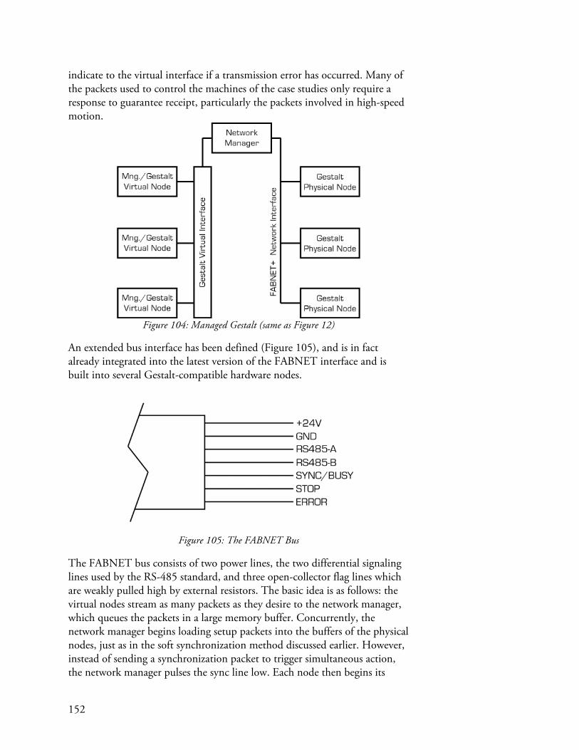
152
indicate to the virtual interface if a transmission error has occurred. Many of the packets used to control the machines of the case studies only require a response to guarantee receipt, particularly the packets involved in high-speed motion.
Figure 104: Managed Gestalt (same as Figure 12)
An extended bus interface has been defined (Figure 105), and is in fact already integrated into the latest version of the FABNET interface and is built into several Gestalt-compatible hardware nodes.
Figure 105: The FABNET Bus
The FABNET bus consists of two power lines, the two differential signaling lines used by the RS-485 standard, and three open-collector flag lines which are weakly pulled high by external resistors. The basic idea is as follows: the virtual nodes stream as many packets as they desire to the network manager, which queues the packets in a large memory buffer. Concurrently, the network manager begins loading setup packets into the buffers of the physical nodes, just as in the soft synchronization method discussed earlier. However, instead of sending a synchronization packet to trigger simultaneous action, the network manager pulses the sync line low. Each node then begins its

153
move and latches the sync line low until its move is finished. As soon as all nodes are finished, the sync line returns high, indicating to the network manager that they are ready for another synchronization pulse. So long as there are an outstanding number of unexecuted moves in the physical node buffers, the network manager continues to pulse sync low and then listens for it to go high before repeating. This strategy allows a constant stream of packets to be sent to the nodes with no latency, and with resynchronization after each packet. The ‘stop’ signal line is used to indicate that a buffer is full in a physical node and that the network manager should hold off on sending subsequent packets until the line is released. The ‘error’ line indicates a transmission error, which the network manager would then sort out to determine what went wrong and how to respond. It is possible that little modification will be required to the Gestalt framework to implement this managed network approach, as the current generation of a sync packet would be replaced with a hardware strobe. However, there is a question of how virtual nodes, which current require a response to any request, will elegantly be able to handle both modalities of synchronization.