a framework for mobile collaborative applications on ...madhumita/aps2/references/gcs/a framework...
TRANSCRIPT
A Framework for Mobile CollaborativeApplications on Mobile Phones
Carl-Henrik Wolf Lundand
Michael Sars Norum
TDT4735 Software Engineering, Depth StudyNovember 23, 2004
Teaching supervisor:Alf Inge Wang
Norwegian University of Science and Technology,Department of Computer and Information Science

Abstract
This project explores the domain of collaborative applications using mobile phones andPersonal Area Networks (PANs) from a technical perspective, resulting in a design andimplementation of a framework for developing such applications.
This paper describes central, theoretical concepts connected to Peer-to-Peer (P2P) com-puting, Mobile Ad Hoc NETworks (MANETs) and the Computer Supported CooperativeWork (CSCW) domains, focusing on “Same-Place-Same-Time” collaboration. We arguehow the spread of PAN technology and mobile phones enable for a broad range of collabo-rative applications supporting both collocated work and spontaneous interaction. We alsopresent a wide study of available technologies for one family of MANETs, PANs.
We then present and classify several usage scenarios of collaborative applications on mobilephones and study the scenarios in detail, producing a set of requirements for a framework.These requirements are then used to iteratively design and implement a network inde-pendent framework with support for Java 2 Micro Edition. In addition to the frameworkitself, the design and implementation of a Bluetooth network module for the frameworkis included. The Bluetooth module serves two purposes: To show how a network modulecan be implemented in order to be used by the framework, and to function as an exam-ple network during testing. Prototype applications are developed to illustrate how theframework can be used to develop collaborative applications and shorten the developmenttime.
The main results of this project are the theoretical conclusions drawn from our domainstudies, the usage scenarios and the software produced.


Preface
This project has been carried out by Carl-Henrik Wolf Lund and Michael Sars Norum fromAugust to November in 2004. The studies performed are related to the course TDT4735System Engineering Depth Study, being a part of the fifth year of the Master in Technologydegree in Computer Sciences at the Norwegian University of Science and Technology. Theproject was assigned by the Department of Computer and Information Science.
Acknowledgements
We would like to thank Alf Inge Wang for his guidance and sharing of expertise duringthe writing of this report. The support and advice he has given us has been invaluable tous along the way.
Trondheim November 23, 2004.
Carl-Henrik Wolf Lund Michael Sars Norum
i

ii
Contents
1 Introduction 1
1.1 Motivation . . . . . . . . . . . . . . . . . . . . . . . . . . . . . . . . . . . . 2
1.2 Problem Definition . . . . . . . . . . . . . . . . . . . . . . . . . . . . . . . . 3
1.3 Project Context . . . . . . . . . . . . . . . . . . . . . . . . . . . . . . . . . . 3
1.4 Limitation of Scope . . . . . . . . . . . . . . . . . . . . . . . . . . . . . . . . 4
1.5 Reader’s Guide . . . . . . . . . . . . . . . . . . . . . . . . . . . . . . . . . . 4
2 Method 6
2.1 Prestudy and Scenario Building . . . . . . . . . . . . . . . . . . . . . . . . . 6
2.2 Scenario Analysis and Requirements Engineering . . . . . . . . . . . . . . . 6
2.3 The Design and Development Cycle . . . . . . . . . . . . . . . . . . . . . . 8
2.4 Tools . . . . . . . . . . . . . . . . . . . . . . . . . . . . . . . . . . . . . . . . 8
2.4.1 Eclipse . . . . . . . . . . . . . . . . . . . . . . . . . . . . . . . . . . . 8
2.4.2 Borland Together Control Center . . . . . . . . . . . . . . . . . . . . 9
2.4.3 Phone Emulator . . . . . . . . . . . . . . . . . . . . . . . . . . . . . 9
I Prestudy 11
3 Central Concepts 13
3.1 Peer-to-peer computing . . . . . . . . . . . . . . . . . . . . . . . . . . . . . 13
3.1.1 Architectures . . . . . . . . . . . . . . . . . . . . . . . . . . . . . . . 16
3.1.2 Applications . . . . . . . . . . . . . . . . . . . . . . . . . . . . . . . 16
3.1.3 Mobile P2P . . . . . . . . . . . . . . . . . . . . . . . . . . . . . . . . 18
3.2 Mobile Ad Hoc Networks . . . . . . . . . . . . . . . . . . . . . . . . . . . . 19
iii
CONTENTS
3.3 Collaboration . . . . . . . . . . . . . . . . . . . . . . . . . . . . . . . . . . . 22
3.3.1 Computer Supported Cooperative Work . . . . . . . . . . . . . . . . 23
3.3.2 Mobile Computer Supported Cooperative Work . . . . . . . . . . . 24
4 Related Projects 28
4.1 Prototypes . . . . . . . . . . . . . . . . . . . . . . . . . . . . . . . . . . . . 28
4.1.1 iClouds - Peer-to-Peer Information Sharing in Mobile Environments 29
4.1.2 IPAD/Hummingbird . . . . . . . . . . . . . . . . . . . . . . . . . . . 31
4.2 Frameworks and Architectures . . . . . . . . . . . . . . . . . . . . . . . . . 31
4.2.1 JXTA . . . . . . . . . . . . . . . . . . . . . . . . . . . . . . . . . . . 33
4.2.2 JXTA for J2ME Proxied . . . . . . . . . . . . . . . . . . . . . . . . . 34
4.2.3 JXTA for J2ME Proxyless . . . . . . . . . . . . . . . . . . . . . . . . 34
4.2.4 Proem . . . . . . . . . . . . . . . . . . . . . . . . . . . . . . . . . . . 35
4.2.5 The Spectre Framework . . . . . . . . . . . . . . . . . . . . . . . . . 37
5 New Technology 39
5.1 Wireless Enabled Devices . . . . . . . . . . . . . . . . . . . . . . . . . . . . 40
5.2 Implementation Platforms . . . . . . . . . . . . . . . . . . . . . . . . . . . . 41
5.2.1 Java 2 Micro Edition . . . . . . . . . . . . . . . . . . . . . . . . . . . 41
5.3 Wireless Technologies . . . . . . . . . . . . . . . . . . . . . . . . . . . . . . 42
5.3.1 Wireless Firewire . . . . . . . . . . . . . . . . . . . . . . . . . . . . . 42
5.3.2 Wireless USB . . . . . . . . . . . . . . . . . . . . . . . . . . . . . . . 44
5.3.3 Bluetooth . . . . . . . . . . . . . . . . . . . . . . . . . . . . . . . . . 46
5.3.4 ZigBee . . . . . . . . . . . . . . . . . . . . . . . . . . . . . . . . . . . 49
5.3.5 Wireless Local Area Network . . . . . . . . . . . . . . . . . . . . . . 53
5.3.6 Summary . . . . . . . . . . . . . . . . . . . . . . . . . . . . . . . . . 54
6 Evaluation 56
6.1 Evaluation of Related Projects . . . . . . . . . . . . . . . . . . . . . . . . . 56
6.1.1 Prototypes . . . . . . . . . . . . . . . . . . . . . . . . . . . . . . . . 56
6.1.2 Frameworks and Architectures . . . . . . . . . . . . . . . . . . . . . 57
6.2 Technology Evaluation . . . . . . . . . . . . . . . . . . . . . . . . . . . . . . 58
6.2.1 Wireless Enabled Devices . . . . . . . . . . . . . . . . . . . . . . . . 58
6.2.2 Implementation Platforms . . . . . . . . . . . . . . . . . . . . . . . . 59
6.2.3 Wireless Technologies . . . . . . . . . . . . . . . . . . . . . . . . . . 59
6.3 Conclusion . . . . . . . . . . . . . . . . . . . . . . . . . . . . . . . . . . . . 59
iv
CONTENTS
II Scenario and requirements analysis and evaluation 63
7 Scenarios 65
7.1 Classification Matrix . . . . . . . . . . . . . . . . . . . . . . . . . . . . . . . 65
7.2 Previously Created Scenarios . . . . . . . . . . . . . . . . . . . . . . . . . . 66
7.2.1 Strategy game . . . . . . . . . . . . . . . . . . . . . . . . . . . . . . 66
7.2.2 Information Exchange . . . . . . . . . . . . . . . . . . . . . . . . . . 67
7.2.3 Business Card Exchange . . . . . . . . . . . . . . . . . . . . . . . . . 67
7.2.4 Tank Game . . . . . . . . . . . . . . . . . . . . . . . . . . . . . . . . 68
7.2.5 Synchronization . . . . . . . . . . . . . . . . . . . . . . . . . . . . . 68
7.3 New Scenarios . . . . . . . . . . . . . . . . . . . . . . . . . . . . . . . . . . 69
7.3.1 Converging Top Ten List . . . . . . . . . . . . . . . . . . . . . . . . 69
7.3.2 Tourist Information . . . . . . . . . . . . . . . . . . . . . . . . . . . 70
7.3.3 Ubiqutous Flea-market . . . . . . . . . . . . . . . . . . . . . . . . . . 71
7.3.4 Planning the Next Meeting . . . . . . . . . . . . . . . . . . . . . . . 73
7.3.5 PAN Instant Messaging . . . . . . . . . . . . . . . . . . . . . . . . . 74
7.4 Summary . . . . . . . . . . . . . . . . . . . . . . . . . . . . . . . . . . . . . 76
8 Scenario Analysis 77
8.1 Goal Analysis . . . . . . . . . . . . . . . . . . . . . . . . . . . . . . . . . . . 78
8.1.1 Concrete Scenario Goals . . . . . . . . . . . . . . . . . . . . . . . . . 79
8.1.2 Requirements Elaboration . . . . . . . . . . . . . . . . . . . . . . . . 80
8.2 Inbound Event Analysis . . . . . . . . . . . . . . . . . . . . . . . . . . . . . 81
8.2.1 Event Identification . . . . . . . . . . . . . . . . . . . . . . . . . . . 81
8.2.2 Requirements Elaboration . . . . . . . . . . . . . . . . . . . . . . . . 83
8.3 Categorize System Output . . . . . . . . . . . . . . . . . . . . . . . . . . . . 84
8.3.1 Event Identification . . . . . . . . . . . . . . . . . . . . . . . . . . . 84
8.3.2 Requirements Elaboration . . . . . . . . . . . . . . . . . . . . . . . . 85
v
CONTENTS
9 Requirements 86
9.1 Previously Gathered Requirements . . . . . . . . . . . . . . . . . . . . . . . 86
9.1.1 Functional Requirements . . . . . . . . . . . . . . . . . . . . . . . . 86
9.1.2 Non Functinal Requirements . . . . . . . . . . . . . . . . . . . . . . 87
9.2 Requirements Evaluation . . . . . . . . . . . . . . . . . . . . . . . . . . . . 88
9.2.1 Removal of Requirements . . . . . . . . . . . . . . . . . . . . . . . . 88
9.2.2 Related Requirements . . . . . . . . . . . . . . . . . . . . . . . . . . 89
9.2.3 Additional Requirement . . . . . . . . . . . . . . . . . . . . . . . . . 90
9.3 Revised Prioritized Requirements . . . . . . . . . . . . . . . . . . . . . . . . 90
III Design 93
10 Designing the Framework 95
10.1 Domain Concepts . . . . . . . . . . . . . . . . . . . . . . . . . . . . . . . . . 95
10.2 High-Level Architecture . . . . . . . . . . . . . . . . . . . . . . . . . . . . . 97
10.3 The Framework Design . . . . . . . . . . . . . . . . . . . . . . . . . . . . . . 98
10.3.1 The Framework Package . . . . . . . . . . . . . . . . . . . . . . . . . 98
10.3.2 The Domain Package . . . . . . . . . . . . . . . . . . . . . . . . . . . 100
10.3.3 The Network Package . . . . . . . . . . . . . . . . . . . . . . . . . . 102
10.3.4 Runtime Behaviour . . . . . . . . . . . . . . . . . . . . . . . . . . . . 103
10.4 Bluetooth Design . . . . . . . . . . . . . . . . . . . . . . . . . . . . . . . . . 105
10.4.1 The Bluetooth Package . . . . . . . . . . . . . . . . . . . . . . . . . 107
10.4.2 The Domain Package . . . . . . . . . . . . . . . . . . . . . . . . . . . 107
10.4.3 The Network Package . . . . . . . . . . . . . . . . . . . . . . . . . . 110
10.5 Prototype Applications . . . . . . . . . . . . . . . . . . . . . . . . . . . . . . 111
10.5.1 DemoMIDlet . . . . . . . . . . . . . . . . . . . . . . . . . . . . . . . 112
10.5.2 ChatApp . . . . . . . . . . . . . . . . . . . . . . . . . . . . . . . . . 112
IV Implementation 115
11 Covered Requirements 117
vi
CONTENTS
12 Code Summary 120
12.1 Code Statistics . . . . . . . . . . . . . . . . . . . . . . . . . . . . . . . . . . 120
12.2 Code Examples . . . . . . . . . . . . . . . . . . . . . . . . . . . . . . . . . . 120
12.2.1 Dynamic Loading of Network Module . . . . . . . . . . . . . . . . . 121
12.2.2 Finding Remote Nodes . . . . . . . . . . . . . . . . . . . . . . . . . . 122
12.2.3 DemoMIDlet . . . . . . . . . . . . . . . . . . . . . . . . . . . . . . . 122
13 Testing 125
14 Tool Evaluation 128
14.1 Eclipse . . . . . . . . . . . . . . . . . . . . . . . . . . . . . . . . . . . . . . . 128
14.2 Borland Together Control Center . . . . . . . . . . . . . . . . . . . . . . . . 128
14.3 Emulators . . . . . . . . . . . . . . . . . . . . . . . . . . . . . . . . . . . . . 129
V Evaluation 131
15 Encountered Problems 133
15.1 The Mobile Phones . . . . . . . . . . . . . . . . . . . . . . . . . . . . . . . . 133
15.1.1 Mobile Phones versus Emulators . . . . . . . . . . . . . . . . . . . . 133
15.1.2 The Sony Ericsson Bluetooth Implementation . . . . . . . . . . . . . 133
15.2 Bluetooth . . . . . . . . . . . . . . . . . . . . . . . . . . . . . . . . . . . . . 134
16 Own Contribution 135
17 Conclusions 137
18 Future Work 139
18.1 Framework Design and Implementation . . . . . . . . . . . . . . . . . . . . 139
18.1.1 Functionality . . . . . . . . . . . . . . . . . . . . . . . . . . . . . . . 139
18.1.2 Optimalization . . . . . . . . . . . . . . . . . . . . . . . . . . . . . . 140
18.1.3 Reliability . . . . . . . . . . . . . . . . . . . . . . . . . . . . . . . . . 140
18.2 Building Applications . . . . . . . . . . . . . . . . . . . . . . . . . . . . . . 140
vii

CONTENTS
VI Appendix 141
A Dictionary 143
B DemoMidlet Source Code 145
viii
List of Tables
3.1 CSCW dimensions. . . . . . . . . . . . . . . . . . . . . . . . . . . . . . . . . 23
4.1 Communication combinations in iCloud with their corresponding real worldinteractions. . . . . . . . . . . . . . . . . . . . . . . . . . . . . . . . . . . . . 31
5.1 Evaluation criteria with weigths. . . . . . . . . . . . . . . . . . . . . . . . . 41
5.2 Overall evaluation of the Wireless Firewire technology. . . . . . . . . . . . . 44
5.3 Overall evaluation of the WUSB technology. . . . . . . . . . . . . . . . . . . 46
5.4 Overall evaluation of the Bluetooth technology. . . . . . . . . . . . . . . . . 50
5.5 Overall evaluation of the ZigBee technology. . . . . . . . . . . . . . . . . . . 52
5.6 Overall evaluation of the WLAN technology. . . . . . . . . . . . . . . . . . . 54
5.7 Summary of the wireless technologies. . . . . . . . . . . . . . . . . . . . . . 55
6.1 Total scores from the individual technology evaluations. . . . . . . . . . . . 59
7.1 Classification matrix. . . . . . . . . . . . . . . . . . . . . . . . . . . . . . . . 66
7.2 Summary of the categorized scenarios. . . . . . . . . . . . . . . . . . . . . . 76
9.1 Revised and prioritized functional requirements. . . . . . . . . . . . . . . . 91
9.2 Revised and prioritized non-functional requirements. . . . . . . . . . . . . . 91
11.1 Covered non-functional requirements. . . . . . . . . . . . . . . . . . . . . . . 117
11.2 Covered functional requirements. . . . . . . . . . . . . . . . . . . . . . . . . 119
12.1 Code statistics. . . . . . . . . . . . . . . . . . . . . . . . . . . . . . . . . . . 121
ix
List of Figures
2.1 The overall project process. . . . . . . . . . . . . . . . . . . . . . . . . . . . 7
3.1 Taxonomy of computer systems [51]. . . . . . . . . . . . . . . . . . . . . . . 14
3.2 Pure P2P Model. . . . . . . . . . . . . . . . . . . . . . . . . . . . . . . . . . 17
3.3 Hybrid P2P Model. . . . . . . . . . . . . . . . . . . . . . . . . . . . . . . . . 17
3.4 Taxonomy of ad hoc networks [12]. . . . . . . . . . . . . . . . . . . . . . . . 21
3.5 A singlehop ad hoc network [1]. . . . . . . . . . . . . . . . . . . . . . . . . . 21
3.6 A multihop ad hoc network [1]. . . . . . . . . . . . . . . . . . . . . . . . . . 22
3.7 A scatternet comprising three piconets [3]. . . . . . . . . . . . . . . . . . . . 23
3.8 A PAN creates a digital sphere around a person. . . . . . . . . . . . . . . . 25
3.9 Three persons physically collocated. . . . . . . . . . . . . . . . . . . . . . . 26
4.1 JXTA For J2ME using proxy service. . . . . . . . . . . . . . . . . . . . . . . 35
4.2 Proxyless JXME. . . . . . . . . . . . . . . . . . . . . . . . . . . . . . . . . . 36
4.3 Spectre main package structure [30]. . . . . . . . . . . . . . . . . . . . . . . 38
5.1 The Usable, Useful and Used hierarchy. . . . . . . . . . . . . . . . . . . . . 40
5.2 Network topology of a 802.15.3 piconet. . . . . . . . . . . . . . . . . . . . . 43
5.3 A WUSB cluster. . . . . . . . . . . . . . . . . . . . . . . . . . . . . . . . . . 45
5.4 The ZigBee Star network. . . . . . . . . . . . . . . . . . . . . . . . . . . . . 51
5.5 The ZigBee Mesh network. . . . . . . . . . . . . . . . . . . . . . . . . . . . 51
5.6 The ZigBee Cluster Tree. . . . . . . . . . . . . . . . . . . . . . . . . . . . . 52
6.1 The central concepts related to this project. . . . . . . . . . . . . . . . . . . 60
8.1 The steps of scenario-based requirements analysis. . . . . . . . . . . . . . . 78
x
LIST OF FIGURES
10.1 The relation bewteen the variuos domain concepts. . . . . . . . . . . . . . . 96
10.2 Overview of the framework architecture. The framework includes all theboxes above “J2ME + Network specific APIs”. . . . . . . . . . . . . . . . . 97
10.3 A logical architectural view showing the main packages. . . . . . . . . . . . 98
10.4 UML for the Framework package. . . . . . . . . . . . . . . . . . . . . . . . . 99
10.5 UML for the Domain package. . . . . . . . . . . . . . . . . . . . . . . . . . . 101
10.6 UML for the Network package. . . . . . . . . . . . . . . . . . . . . . . . . . 103
10.7 Sequnce diagram for an application wanting to receive incoming connections.104
10.8 The process of initializing the framework. . . . . . . . . . . . . . . . . . . . 104
10.9 The process of searching for other devices with applications running thesame service. . . . . . . . . . . . . . . . . . . . . . . . . . . . . . . . . . . . 105
10.10The process of sending a message. . . . . . . . . . . . . . . . . . . . . . . . 106
10.11Overview of the Bluetooth protocol stack. . . . . . . . . . . . . . . . . . . . 107
10.12UML for the Bluetooth package. . . . . . . . . . . . . . . . . . . . . . . . . 108
10.13UML for Bluetooth Domain package. . . . . . . . . . . . . . . . . . . . . . . 109
10.14UML for the Bluetooth Network package. . . . . . . . . . . . . . . . . . . . 113
10.15UML for DemoMIDlet . . . . . . . . . . . . . . . . . . . . . . . . . . . . . . 114
10.16UML for ChatApp . . . . . . . . . . . . . . . . . . . . . . . . . . . . . . . . 114
12.1 Dynamic loading of network module. . . . . . . . . . . . . . . . . . . . . . . 121
12.2 Connecting to a remote device and querying for services. . . . . . . . . . . . 122
12.3 Initializing the framework and registering a service. . . . . . . . . . . . . . . 123
12.4 Handling a discovered group. . . . . . . . . . . . . . . . . . . . . . . . . . . 124
12.5 Beeing notified of a new node joining a group. . . . . . . . . . . . . . . . . . 124
13.1 Testing the framework on the Nokia Emulator. . . . . . . . . . . . . . . . . 126
xi

LIST OF FIGURES
xii
Chapter 1
Introduction
Over the past 20 years, the influence computers have on our lives and the work carriedout by us has grown. Our use of computers have gone from non-connected standaloneapplications, to being used for collaborative work where several actors can contribute toworkprocesses without being collocated, both physically and time-wise.
The recent years have shown a tendency where computers have become more and moreportable to fit the needs of users on the move. This tendency has further been strengthenedby the growth in the mobile phones user base in parallel with the increasing computationalcapacity of the mobile phones. Today, mobile phones have the same computational capac-ity of the late 80’s computers with one important addition. Mobile phones are constantlyconnected to a network, making them available for collaborative work anywhere and any-time.
The use of handheld and other portable devices in collaboration is not a new idea, butis still a quite immature research field. Researchers have faced many problems in theresearch conducted on Computer Supported Cooperative Work (CSCW) using full scalecomputers, many which they have been unable to solve. The same difficulties will bepresent on more limited portable devices, but the portable devices can draw benefits fromaspects such as mobility possibly making them more suitable for usage in certain areas ofCSCW.
Although having limited capacity, the mobile phones have a quite clear advantage over thetraditional stationary computers and even laptop computers. Mobile phones are mobileto an extreme degree, providing us with always on, omnipresent computational devices.When using a mobile phone for collaborative applications, it is always available to beused in the collaborative process. Also the spread of mobile phones among the potentialusers and their familiarity with them, make them an ideal deployment platform for CSCWapplications.
This project will aim to design and implement a framework used to create collaborativeapplications on mobile phones. The emergence of mobile phones with some kind of ad hocnetwork technology built-in creates opportunities for new forms of computerized collabo-ration. Mobile, computer supported, collaboration between people that are collocated isnow possible.
1
Introduction
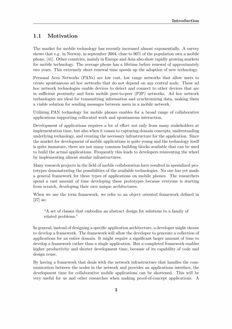
1.1 Motivation
The market for mobile technology has recently increased almost exponentially. A surveyshows that e.g. in Norway, in september 2004, close to 96% of the population own a mobilephone, [41]. Other countries, mainly in Europe and Asia also show rapidly growing marketsfor mobile technology. The average phone has a lifetime before renewal of approximatelytwo years. This extremely short renewal time speeds up the adoption of new technology.
Personal Area Networks (PANs) are low cost, low range networks that allow users tocreate spontaneous ad hoc networks that do not depend on any central node. These adhoc network technologies enable devices to detect and connect to other devices that arein sufficient proximity and form mobile peer-to-peer (P2P) networks. Ad hoc networktechnologies are ideal for transmitting information and synchronizing data, making thema viable solution for sending messages between users in a mobile network.
Utilizing PAN technology for mobile phones enables for a broad range of collaborativeapplications supporting collocated work and spontaneous interaction.
Development of applications requires a lot of effort not only from many stakeholders atimplementation time, but also when it comes to capturing domain concepts, understandingunderlying technology, and creating the necessary infrastructure for the application. Sincethe market for development of mobile applications is quite young and the technology itselfis quite immature, there are not many common building blocks available that can be usedto build the actual applications. Frequently this leads to developers reinventing the wheelby implementing almost similar infrastructures.
Many research projects in the field of mobile collaboration have resulted in spesialized pro-totypes demonstrating the possibilities of the available technologies. No one has yet madea general framework for these types of applications on mobile phones. The researchersspend a vast amount of time developing these prototypes because everyone is startingfrom scratch, developing their own unique architectures.
When we use the term framework, we refer to an object oriented framework defined in[27] as:
“A set of classes that embodies an abstract design for solutions to a family ofrelated problems.”
In general, instead of designing a specific application architecture, a developer might chooseto develop a framework. The framework will allow the developer to generate a collection ofapplications for an entire domain. It might require a significant larger amount of time todevelop a framework rather than a single application. But a completed framework enableshigher productivity and shorter development time, because of its capability of code anddesign reuse.
By having a framework that deals with the network infrastructure that handles the com-munication between the nodes in the network and provides an applications interface, thedevelopment time for collaborative mobile applications can be shortened. This will bevery useful for us and other researches when making proof-of-concept applications. A
2
1.2 Problem Definition
well documented framework will also establish terms and definitions that can be used byresearchers and other participants in the research field. A framework for developing ap-plications will also hopefully reduce the time before someone creates a killer applicationthat will help the field of mobile collaboration to gain acceptance in the consumer market.
All in all we would like to contribute to the development of a standard for ad hoc collab-oration applications on mobile phones.
1.2 Problem Definition
This project aims to design and implement a framework for developing collaborative ap-plications on mobile phones. Central concepts such as P2P networks, Mobile Ad HocNetworks (MANET) and CSCW will be studied and described. To obtain a completepicture of the research domain and to take the right design decisions, the most importantrelevant research projects and different PAN technologies will be described and evaluated.To make the framework as generic as possible different kind of usage scenarios should bedeveloped. In [30] Sveen and Kirkhus proposed a set of requirements for a frameworkdesign. These requirements should be used to verify the requirements extracted from thescenarios. Further the framework should be iteratively designed and implemented.
Given the task of implementing a framework, the focus of this project will be technicalrather than focusing on CSCW in general.
1.3 Project Context
The work documented in this report is related to the MObile Work Across HeterogenerousSystems (MOWAHS1) project. The MOWAHS project is a joint research effort by thesoftware engineering and the database technology groups at the Department for Computerand Information Science (IDI) at the Norwegian University of Science and Technology(NTNU).
The goals of the MOWAHS project are (as listed on the MOWAHS website):
• Helping to understand and to continuously assess and improve workprocesses invirtual organizations.
• Providing a flexible, common work environment to execute and share real workpro-cesses and their artifacts, applicable on a variety of electronic devices (from bigservers to small PDAs).
• Disseminating the results to colleagues, students, companies, and the community atlarge.
The aim of this project is to contribute to the second goal of the MOWAHS project. Byproducing a framework for the development of mobile ad hoc applications for supportingcollaboration, we hope to give a useful contribution to MOWAHS.
1http://www.mowahs.com
3
Introduction
1.4 Limitation of Scope
As mentioned in our problem definition, Chapter 1.2, the main goal of this project is todesign and implement a framework for collaborative applications on mobile phones. Thisgives us a very technical focus.
Due to the degree of technicality of the project we will limit our studies of the CSCWdomain to a minimum, covering only those aspects necessary to make our design andimplementation choices.
1.5 Reader’s Guide
The focus of the chapters in this report varies quite a lot. Not all readers are equallyinterested in all the information, therefore we will now present a brief readers guide.
Chapter 1 Introduction: This chapter contains background information about theproject such as motivation, problem definiton, project context, limitations of scopeand this readers guide.
Chapter 2 Method: This chapter describes our work process and methologies usedduring the project. It motivates for our choices in methods and gives a brief discus-sion of tools.
Part I Prestudy
Chapter 3 Central Concepts: This chapter discusses central concepts relatedto this project. Domains such as P2P computing and CSCW are discussed.
Chapter 4 Related Projects: This chapter discusses related work. Related pro-totype projects and architectures and frameworks are discussed. It works as asummary of the State-of-the-Art.
Chapter 5 New Technology: This chapter looks at what options we have whenchoosing technologies for this project. The main focus is on wireless technologiesand the chapter is a bit technical.
Chapter 6 Evaluation: This chapter evaluates all related work and new tech-nologies and draws conclusions as to what we will use for the design and im-plementation parts of this project.
Part II Scenario and requirements analysis and evaluation
Chapter 7 Scenarios: This chapter presents usage scenarios for mobile collabo-rative applications using PAN technology, focusing on the user perspective.
Chapter 8 Scenario Analysis: This chapter presents a method for deducing re-quirements from scenarios. This method is then used to extract requirementsfrom the scenarios given in Chapter 7.
Chapter 9 Requirements: This chapter presents all the requirements the frame-work will have to meet.
4
1.5 Reader’s Guide
Part III Design
Chapter 10 Designing the Framework: This chapter presents our design for aframework for mobile collaborative applications on mobile phones. A high-levelarchitecture is presented along with a more detailed presentation of each of thearchitecture components. The Bluetooth specific network design is also pre-sented. This part illustrates how a network design is done in order to functionas a guide for developers wanting to add a new network technology package tothe software suite.
Part IV Implementation
Chapter 11 Covered Requirements: This chapter presents which requirementsthat were fulfilled during implementation.
Chapter 12 Code Summary: This chapter presents some code examples that il-lustrate important aspects of the framework. Some code statistics are alsolisted.
Chapter 13 Testing: This chapter describes the different test techniques used dur-ing implementation.
Chapter 14 Tool Evaluation: This chapter gives a summary of our experienceswith the tools used in this project.
Part V Evaluation
Chapter 15 Encountered Problems: This chapter discusses the problems en-countered during the lifetime of the project.
Chapter 16 Own Contribution: This chapter summarizes the contribution madeby us through this project.
Chapter 17 Conclusions: This chapter describes our conclusions.
Chapter 18 Future Work: This chapter describes some of the areas we see aspossible future work related to the framework and prototype applications.
Part VI Appendix
Appendix A Dictionary: A list describing the most important terms used in thisreport.
Appendix B DemoMidlet Source Code: The source code for the DemoMidletapplication.
5
Chapter 2
Method
Our main goal with this project is to create a framework for collaborative applications onmobile phones. The framework will be designed and implemented as a proof-of-concept.Last we will test our framework through demo-applications, showing that it actual has apractical use for developers of mobile collaborative applications.
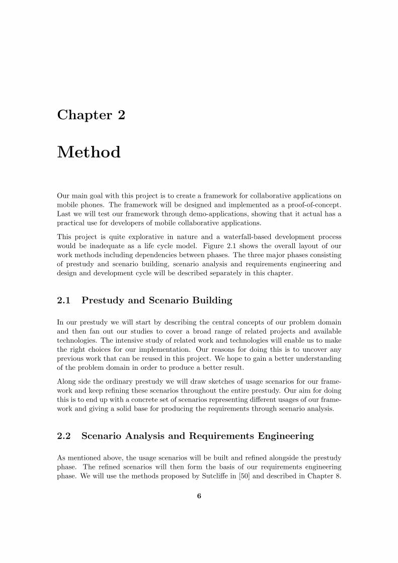
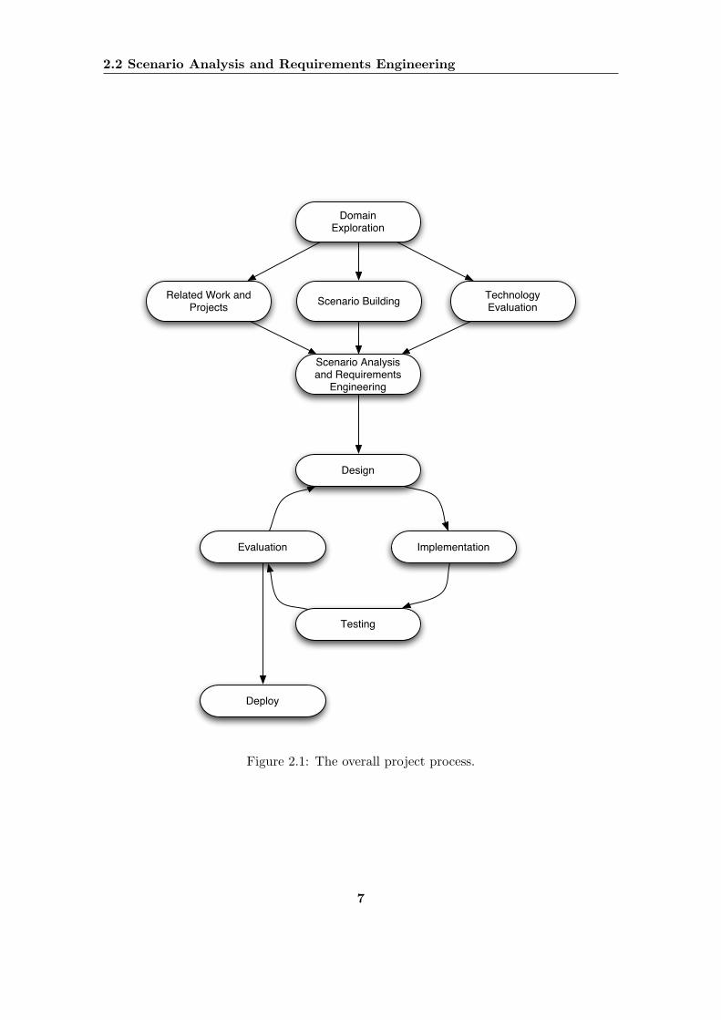
This project is quite explorative in nature and a waterfall-based development processwould be inadequate as a life cycle model. Figure 2.1 shows the overall layout of ourwork methods including dependencies between phases. The three major phases consistingof prestudy and scenario building, scenario analysis and requirements engineering anddesign and development cycle will be described separately in this chapter.
2.1 Prestudy and Scenario Building
In our prestudy we will start by describing the central concepts of our problem domainand then fan out our studies to cover a broad range of related projects and availabletechnologies. The intensive study of related work and technologies will enable us to makethe right choices for our implementation. Our reasons for doing this is to uncover anyprevious work that can be reused in this project. We hope to gain a better understandingof the problem domain in order to produce a better result.
Along side the ordinary prestudy we will draw sketches of usage scenarios for our frame-work and keep refining these scenarios throughout the entire prestudy. Our aim for doingthis is to end up with a concrete set of scenarios representing different usages of our frame-work and giving a solid base for producing the requirements through scenario analysis.
2.2 Scenario Analysis and Requirements Engineering
As mentioned above, the usage scenarios will be built and refined alongside the prestudyphase. The refined scenarios will then form the basis of our requirements engineeringphase. We will use the methods proposed by Sutcliffe in [50] and described in Chapter 8.
6
2.2 Scenario Analysis and Requirements Engineering
Scenario Analysis and Requirements
Engineering
Design
Implementation
Testing
Evaluation
Deploy
Domain Exploration
Related Work and Projects
Technology EvaluationScenario Building
Figure 2.1: The overall project process.
7
Method
In [30], Sveen and Kirkhus conducted work similar to ours and presented as set of re-quirements for a framework for mobile collaborative applications on ad hoc networks. Asmentioned above we will do a complete requirements engineering of our own based on ourscenarios, but will then use Sveen and Kirkus’ requirements to verify and review our ownrequirements for completeness.
2.3 The Design and Development Cycle
The development of applications, and especially networked applications, for mobile phonesraises quite a few issues not present in the development of applications for full scalecomputers, e.g. desktops and servers. Although we have some experiences developingJava for mobile phones from previous projects, we are still on fairly unknown grounds.We will therefore have to use a design and development method enabling us to explorethe possibilities and find the major limitations along the way.
As mentioned previously in this chapter, a traditional waterfall-based development processwould be inadequate for us because of the project’s explorative nature. Thus, we want touse an iterative design and development process as described in Figure 2.1 by the boxeslabeled design, implementation, testing and evaluation. This pattern of designing anddeveloping the software gives the framework an evolutionary lifecycle. This in turn givesus the ability to uncover weaknesses in our design as early as possible and reduces the costassociated with design flaws.
The tests verifying the correctness of the framework will be continuous functional tests andconducted by writing test applications that use the primitives and functionality offered bythe framework.
2.4 Tools
In order to perform the design and development iterations faster, we will try to utilizesoftware packages that support us in our work as much as possible. The three majorsoftware tools we plan to use are Eclipse, Borland Together Control Center and some formof phone emulator for first instance testing.
2.4.1 Eclipse
The Eclipse project1 develops an open source, free Integrated Developer Environment(IDE) which is plugin based and thus supporting various programming languages andcompilers.
Eclipse is a plugin based IDE written in Java giving us the benefit of using the samesoftware independently of the platform on our workstation. Eclipse has built in supportfor Concurrent Versions System (CVS) and can be extended to support emulators formobile phones and writing documents in LATEX.
1http://www.eclipse.org
8
2.4 Tools
2.4.2 Borland Together Control Center
Borland Together Control Center (Borland TCC) is part of Borland’s Together softwaresuite, providing developers with an effective tool for modelling software with Unified Mod-elling Language (UML) diagrams.
Borland TCC keeps the source code and UML diagrams consistent at all times and there-fore gives us an advantage when using an iterative design and implementation cycle. Ifwe decide to test aspects of the framework by writing code, the model is automaticallyupdated to fit this and can be used to view the changes done during implementation.
2.4.3 Phone Emulator
Testing of the framework can be conducted in two ways: On the actual phones, or onsoftware emulating the phones’ behaviour. Testing on the phones themselves can be aquite tedious process as software needs to be packaged and transferred to the phone beforeit can be tested. To save time when testing, we plan to perform as much as possible ofthe testing on emulators to verify logical correctness before trying to test on the phones.
Many different emulators are freely available for download, some of these are:
• The Nokia Developer Kit with Bluetooth stack emulation.
• The Sony Ericsson Wireless Toolkit.
• Sun’s Wireless Toolkit.
9

Method
10

Part I
Prestudy
11

12
Chapter 3
Central Concepts
This chapter describes the central concepts our project will be based upon. We will providean overview of the most important and relevant aspects of P2P computing, MANETsand CSCW. The overview will focus on defining the concepts, describing advantages anddisadvantages, and summarizing the challenges in the different research domains.
3.1 Peer-to-peer computing
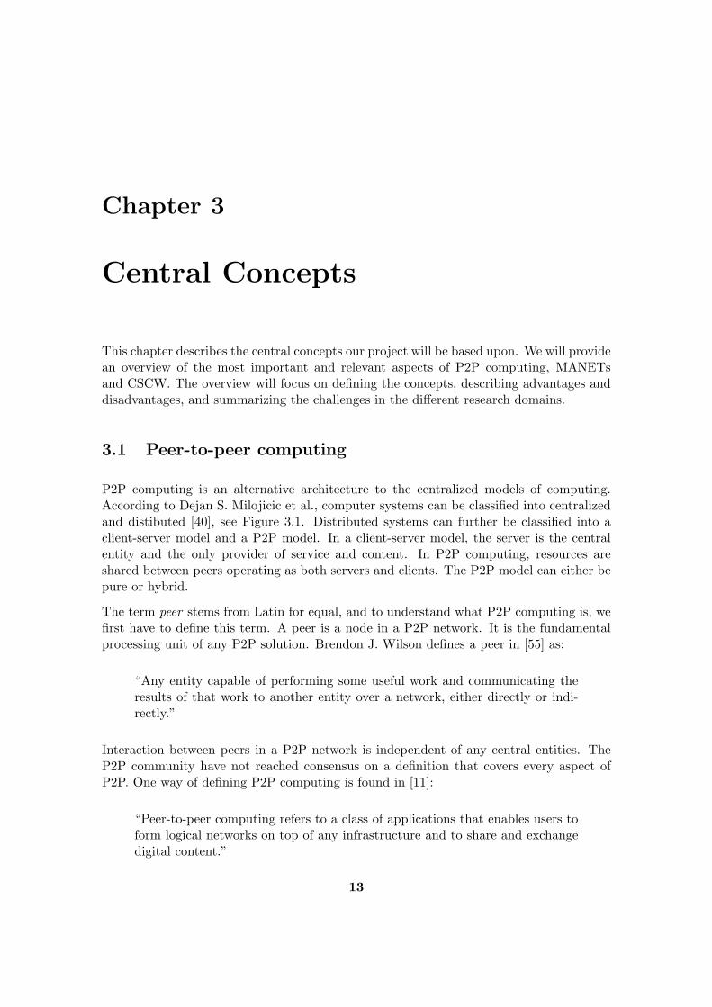
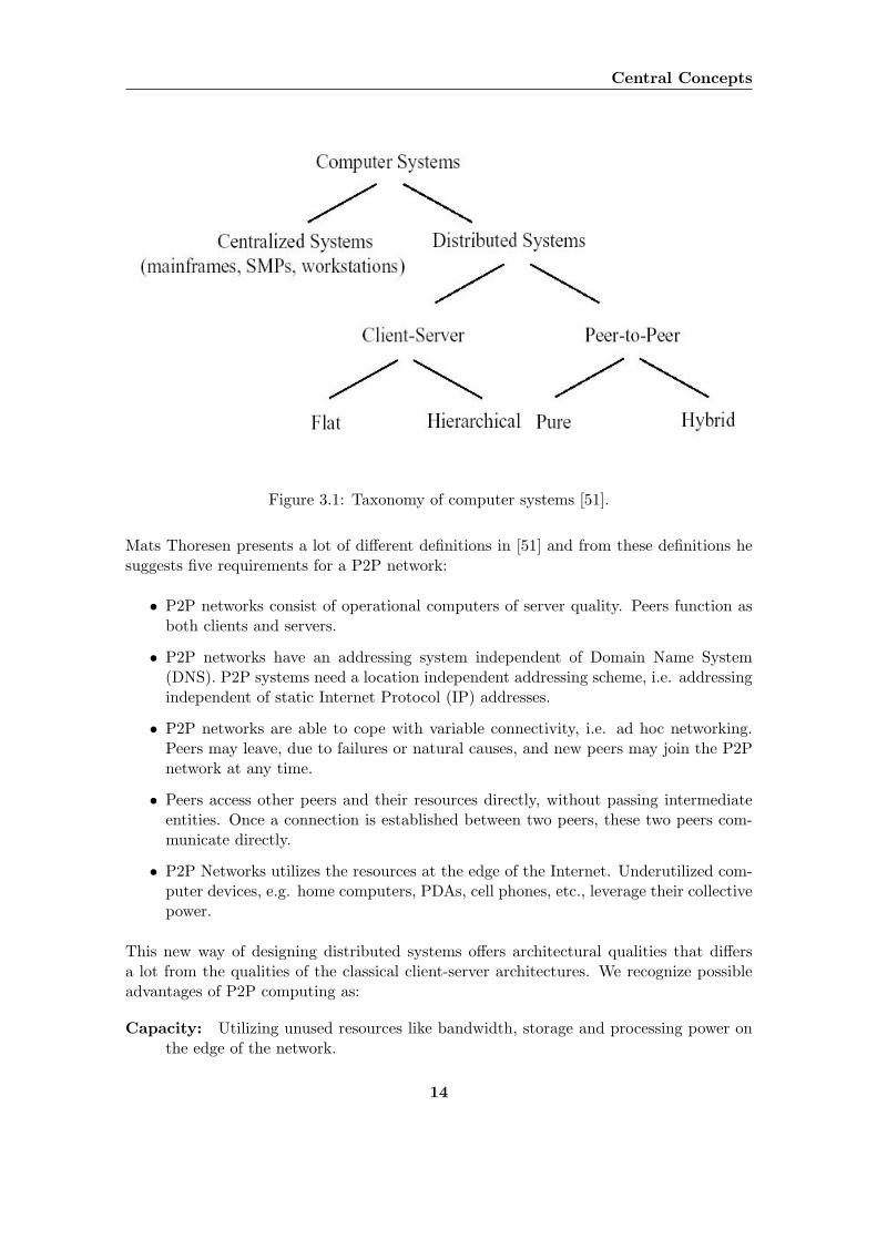
P2P computing is an alternative architecture to the centralized models of computing.According to Dejan S. Milojicic et al., computer systems can be classified into centralizedand distibuted [40], see Figure 3.1. Distributed systems can further be classified into aclient-server model and a P2P model. In a client-server model, the server is the centralentity and the only provider of service and content. In P2P computing, resources areshared between peers operating as both servers and clients. The P2P model can either bepure or hybrid.
The term peer stems from Latin for equal, and to understand what P2P computing is, wefirst have to define this term. A peer is a node in a P2P network. It is the fundamentalprocessing unit of any P2P solution. Brendon J. Wilson defines a peer in [55] as:
“Any entity capable of performing some useful work and communicating theresults of that work to another entity over a network, either directly or indi-rectly.”
Interaction between peers in a P2P network is independent of any central entities. TheP2P community have not reached consensus on a definition that covers every aspect ofP2P. One way of defining P2P computing is found in [11]:
“Peer-to-peer computing refers to a class of applications that enables users toform logical networks on top of any infrastructure and to share and exchangedigital content.”
13
Central Concepts
Figure 3.1: Taxonomy of computer systems [51].
Mats Thoresen presents a lot of different definitions in [51] and from these definitions hesuggests five requirements for a P2P network:
• P2P networks consist of operational computers of server quality. Peers function asboth clients and servers.
• P2P networks have an addressing system independent of Domain Name System(DNS). P2P systems need a location independent addressing scheme, i.e. addressingindependent of static Internet Protocol (IP) addresses.
• P2P networks are able to cope with variable connectivity, i.e. ad hoc networking.Peers may leave, due to failures or natural causes, and new peers may join the P2Pnetwork at any time.
• Peers access other peers and their resources directly, without passing intermediateentities. Once a connection is established between two peers, these two peers com-municate directly.
• P2P Networks utilizes the resources at the edge of the Internet. Underutilized com-puter devices, e.g. home computers, PDAs, cell phones, etc., leverage their collectivepower.
This new way of designing distributed systems offers architectural qualities that differsa lot from the qualities of the classical client-server architectures. We recognize possibleadvantages of P2P computing as:
Capacity: Utilizing unused resources like bandwidth, storage and processing power onthe edge of the network.
14
3.1 Peer-to-peer computing
Independency: A distributed architecture independent of central entities.
Configuration: Because all peers have the same functionality and responsibility thenetwork becomes more autonomous and self-configurable
Decentralization: Because functionality and services can be located anywhere in thenetwork, a P2P network is not introducing bottlenecks in the same way as the client-server architecture does.
Extensibility: Adding new resources and making the system grow is not complicated.A peer can join the network and instantly make new services or resources availableon the network.
Fault tolerance: There is no single point of failure in a P2P network. The networkarchitecture easily provides a natural replication scheme.
Scalability: An obvious benefit of decentralization is scalability. Consumers of resourcesalso produce resources. If a peer does not need a special service or resource, it couldoffer it to other peers. In exchange a peer can get needed resources or services fromother peers. The scalability of a P2P network is limited by the amount of centralizedoperations, like synchronization and coordination.
Although the P2P computing paradigm provides a lot of possible advantages some majorproblems have to be solved before the full potential of P2P systems can be realized. Threemajor challenges are described in [13]:
Searching and routing: How to locate resources and services and route messages be-tween nodes
Resource management: Contribution and allocation of resources
Security and privacy: Prevention from malicous peers and protection of personal in-formation
There is no central mechanism in a P2P network. This means that peers have to searchamong other peers to find the resources and services they are looking for. Peers requestingexactly the same resource from the network might communicate with different peers viadifferent routes, with different results. Requests for resources and services might result inan immediate response or might not result in any response at all.
Resource management deals with how peers should contribute and allocate resources.Because there is no central allocation mechanism, the peers have to decide what kindof services and resources they should provide, and how these will be allocated amongthe peers. The autonomous nature of peers give the possibility not to contribute to thenetwork at all, simply taking advantage of other peers sharing their resources. A solutionto this problem could be to use concepts from economics, for instance constructing amarketplace, where peers can buy and sell or trade resources and services as necessary. Themicroeconomic paradigm was used in the design of Mariposa [49], a wide-area distributed
15
Central Concepts
database system, where all clients and servers negotiate, buy and sell resources from eachother. In this way, queries and responsibility are shared efficiently across the network.
P2P systems, as other computer systems, are exposed to various security threats. Becausepeers are autonomous, some nodes may be malicious and might threaten the security.Malicious peers might attack the availability of the system, so called denial-of-service(DOS) attack. Methods on how to trust peers to provide reliable information have to bedeveloped, and users have to be able to control the use of personal information regardingthemselves.
3.1.1 Architectures
There are two core types of P2P network architectures, called hybrid and pure. The keydistinction between the two architectures is that the hybrid P2P architecture involves oneor more central entity.
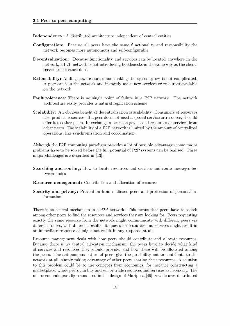
In a pure P2P network, all peers have the same responsibility. There is no central entityresponsibly for managing, controlling or coordinating the services and the resources onthe network. Because all peers have the same responsibility, any peer in the network canbe removed without loosing functionality. Because no central entities exist, much morecomplex routing and location protocols have to be implemented. However, because of thetotally decentralized architecture, applications with high availability, fault-tolerance andgood scalability can be built. Figure 3.2 shows the pure P2P model with peers markedwith the letter P.
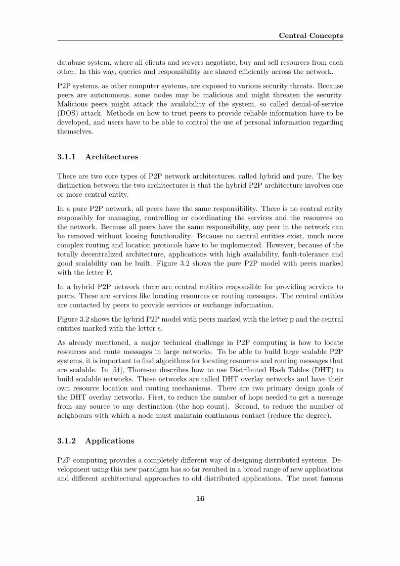
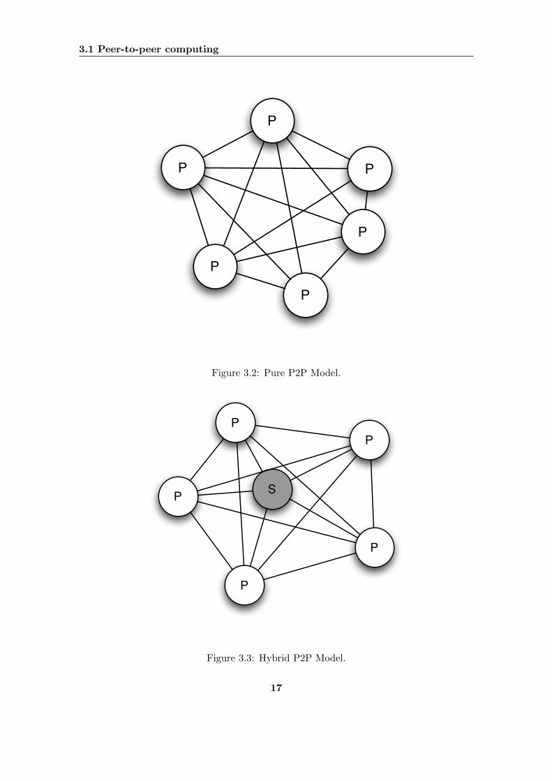
In a hybrid P2P network there are central entities responsible for providing services topeers. These are services like locating resources or routing messages. The central entitiesare contacted by peers to provide services or exchange information.
Figure 3.2 shows the hybrid P2P model with peers marked with the letter p and the centralentities marked with the letter s.
As already mentioned, a major technical challenge in P2P computing is how to locateresources and route messages in large networks. To be able to build large scalable P2Psystems, it is important to find algorithms for locating resources and routing messages thatare scalable. In [51], Thoresen describes how to use Distributed Hash Tables (DHT) tobuild scalable networks. These networks are called DHT overlay networks and have theirown resource location and routing mechanisms. There are two primary design goals ofthe DHT overlay networks. First, to reduce the number of hops needed to get a messagefrom any source to any destination (the hop count). Second, to reduce the number ofneighbours with which a node must maintain continuous contact (reduce the degree).
3.1.2 Applications
P2P computing provides a completely different way of designing distributed systems. De-velopment using this new paradigm has so far resulted in a broad range of new applicationsand different architectural approaches to old distributed applications. The most famous
16
3.1 Peer-to-peer computing
P P
P
P
P
P
Figure 3.2: Pure P2P Model.
PP
P
P S
P
Figure 3.3: Hybrid P2P Model.
17
Central Concepts
applications world wide are file sharing systems like Napster and Gnutella and instantmessengers like Microsoft Messenger and ICQ.
In [44], Schoder and Fischbach identify five different P2P application categories:
Instant Messaging: Applications and/or services for the exchange of messages betweentwo or more interacting parties (humans and/or machines).
Digital Content Sharing: Applications and/or services for the exchange of digital con-tent.
Grid Computing: Applications and/or services that allow customers to send comput-ing tasks to a server application, which manages the distribution, analysis, integritychecks, and security of the data sets to other computers that can offer some process-ing capacity.
Collaboration: Applications and/or services to work or play in ad hoc groups that donot necessarily include organizational hierarchies.
Web Services: Arbitrary pieces of self-contained, descriptive logic packaged in such away that it can be located and invoked programmatically over the Internet usingopen standard network and application protocols
In this project we are going to focus on the category of colloborative applications. Ourframework may still also cover applications of instant messaging and digital content sharingin ad hoc networks.
3.1.3 Mobile P2P
A mobile P2P system should be realized with a pure P2P model. The pure P2P modelallow peers to join the network and to discover peer resources without a server infrastruc-ture.
In [35], mobile P2P is defined as follows:
“A mobile P2P system is a distributed mobile system that consists of mobilehosts that continuously change their physical location and establish peeringrelationships among each other based on proximity.”
A mobile P2P system can be implemented in two different ways:
Without an infrastructure: Using an underlying mobile ad hoc wireless network, likeBluetooth or InfraRed.
With an infrastructure: Using the Internet via a wireless cellular network, like GSMor UMTS.
18
3.2 Mobile Ad Hoc Networks
The framework we are going to design will support functionality of a mobile P2P system.The framework will cover applications that do not rely on an existing infrastructure. Theapplications will be based upon an underlying mobile ad hoc wireless network.
There are clear differences between non-mobile or stationary P2P systems and mobile P2Psystems. Mobile P2P systems are under influences by the general challenges in mobilecomputing. The main categories of challenges are identified in [18] as:
• Communication
• Mobility
• Portability
Communication challenges is about interruption of transfers, problems with low and vary-ing bandwidth, integration of heterogenous networks and security issues. The challenge ofmobility includes difficulties with adressing devices and location-aware information. Porta-bility challenges is about reducing the amount of energy used, the fact that small mobiledevices has small screens and user interfaces, little storage capacity and low CPU power.Mobile P2P systems represents challenges that differs from the challenges in non-mobileP2P systems. Some of these challenges are given in [36]:
Resource discovery: The dynamic nature of mobile P2P systems requires more dynamicmechanisms for device and resource discovery.
Data sharing and synchronization: High availability is desirable to provide autonomouspeers. To obtain this availability some kind of replication scheme has to be deployed.This introduces the very complex problem of consistency between peers.
All these technical challenges makes the design of mobile P2P systems quite difficult. Thenature of mobility introduces possibilities along with difficulties. For example are mobiledevices by definition moving, making people able to facilitate ubiquitous computing. Be-cause the devices are moving, they will over time come in and out of range of each other,causing communication links to fail and transfers to be interrupted. The designer has tobalance these kinds of contradictions to be able to create useful systems.
3.2 Mobile Ad Hoc Networks
MANETs are spontaneous, self-configuring, wireless networks with no fixed infrastructure.As devices supporting ad hoc networking are moved around, they are able to detect andconnect to other devices that are within a given proximity. When the devices are out ofrange from each other, the connections are broken. In this way, the devices form spon-taneous networks with the possibility of exchanging information. The most widespreaddefinition of a MANET is found in [39] and is as follows:
“A mobile ad hoc network is a network formed without any central admin-istration which consists of mobile nodes that use a wireless interface to sendpacket data.”
19
Central Concepts
Todays cellular systems, like the Global System for Mobile communications (GSM) andUniversal Mobile Telecommunication System (UMTS) networks, rely heavily on the in-frastructure. Base stations provides coverage, and services are integrated into the system.This architecture provides good and predictable services, which suits well for cellular tele-phony. Ad hoc networks have a number of advantages compared to traditional wirelesscellular networks [36]:
No infrastructure required: Ad hoc wireless networks do not rely on wired base sta-tions and for that reason can be deployed in places without existing infrastructure.They can be created spontaneously and on as needed basis, because they requirelittle configuration to setup.
Self-organization: In a wired network the connection topology of nodes is determinedby the physical cabling and therefore is fixed. This restriction is not present inan ad hoc network. As soon as two nodes are within proximity of each other, acommunication link between them is automatically formed. As a consequence, thenetwork topology of an ad hoc network reflects the relative distance of its nodes andis continuously reconfigured as nodes come within reach of each other.
Fault tolerance: The self-organizing nature of ad hoc networks and the fact that theydo not rely on dedicated stations makes ad hoc networks fault tolerant. In a tradi-tional cellular network, a fault in the base, will impair all nodes in its cell. In adhoc networks, a malfunction in one node can be easily overcome through networkreconfiguration.
Applications of mobile ad hoc networking have been used by the military since the 1970s.The decentralized nature of ad hoc networks requiring no infrastructure, is a major ad-vantage, and almost a necessity in the battle field. There has also been a lot of researchin using ad hoc networks in disaster and rescue operations. Disasters like fires, floods andearthquakes may destroy the available communication infrastructure and require the de-ployment of an ad hoc network for the rescue teams to be able to communicate. Anotherlarge application domain is sensor networks. All these application areas have commonal-ities in the way that nodes in the networks are strongly related to each other, trust eachother and have a common goal.
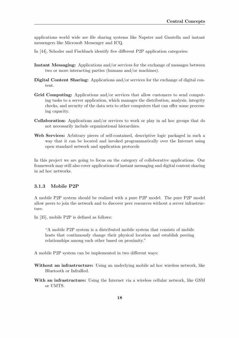
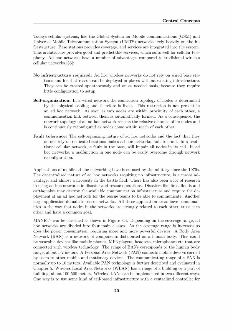
MANETs can be classified as shown in Figure 3.4. Depending on the coverage range, adhoc networks are divided into four main classes. As the coverage range is increases sodoes the power consumption, requiring more and more powerful devices. A Body AreaNetwork (BAN) is a network of components distributed on a human body. This couldbe wearable devices like mobile phones, MP3 players, headsets, microphones etc that areconnected with wireless technology. The range of BANs corresponds to the human bodyrange, about 1-2 meters. A Personal Area Network (PAN) connects mobile devices carriedby users to other mobile and stationary devices. The communicating range of a PAN isnormally up to 10 meters. Available PAN technology is further described and evaluated inChapter 5. Wireless Local Area Networks (WLAN) has a range of a building or a part ofbuilding, about 100-500 meters. Wireless LANs can be implemented in two different ways.One way is to use some kind of cell-based infrastructure with a centralized controller for
20
3.2 Mobile Ad Hoc Networks
Figure 3.4: Taxonomy of ad hoc networks [12].
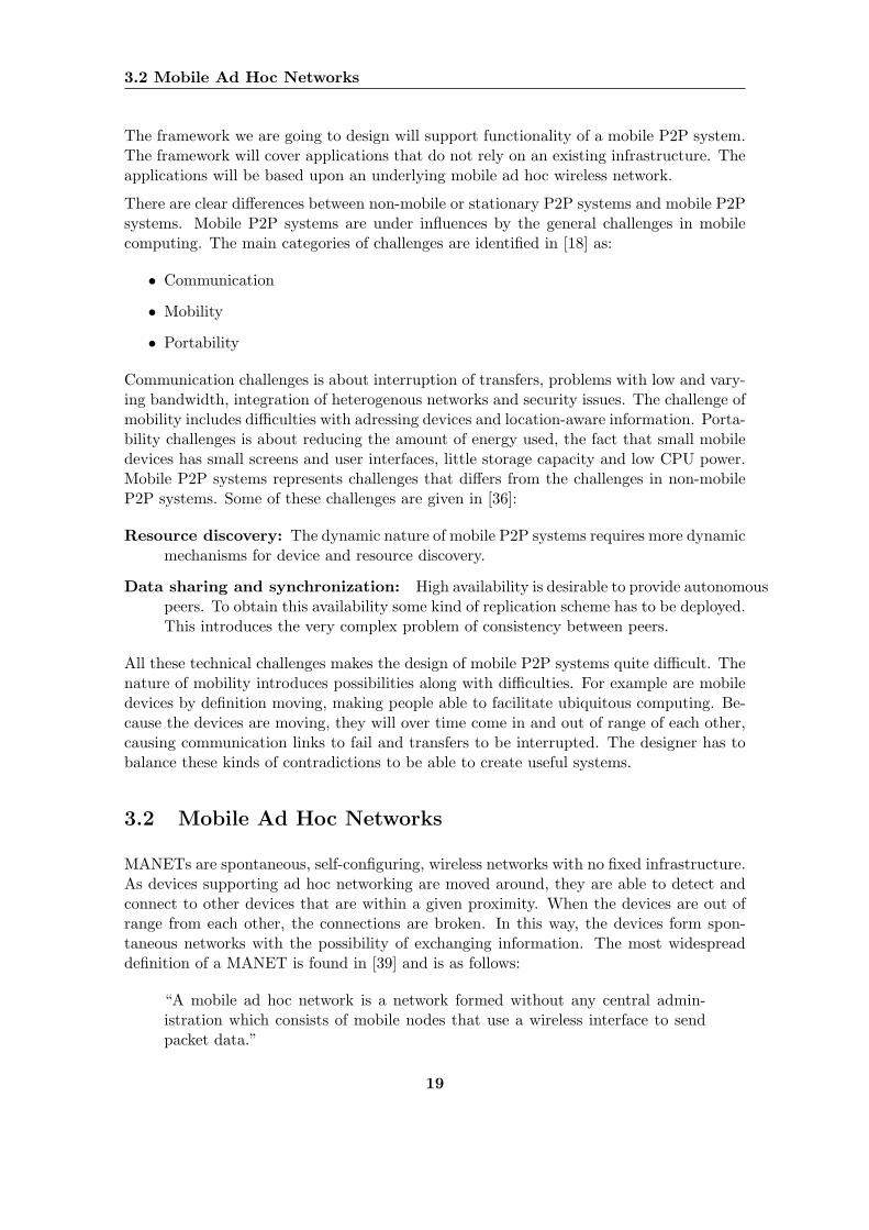
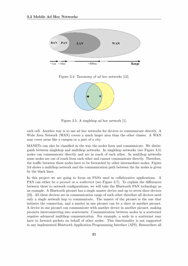
Figure 3.5: A singlehop ad hoc network [1].
each cell. Another way is to use ad hoc networks for devices to communicate directly. AWide Area Network (WAN) covers a much larger area than the other classes. A WANmay cover areas like a campus or a part of a city.
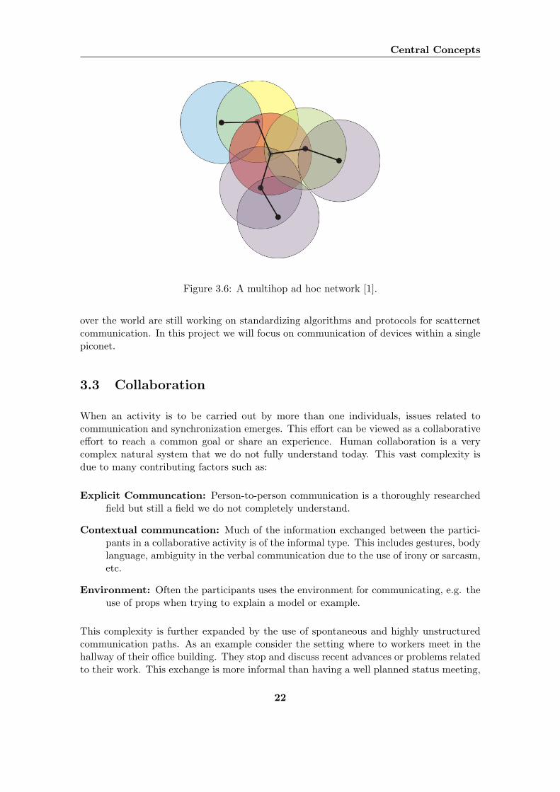
MANETs can also be classified in the way the nodes form and communicate. We distin-guish between singlehop and multihop networks. In singlehop networks (see Figure 3.5)nodes can communicate directly and are in reach of each other. In multihop networkssome nodes are out of reach from each other and cannot communicate directly. Therefore,the traffic between these nodes have to be forwarded by other intermediate nodes. Figure3.6 shows a multihop network and the communication path between the far nodes is givenby the black lines.
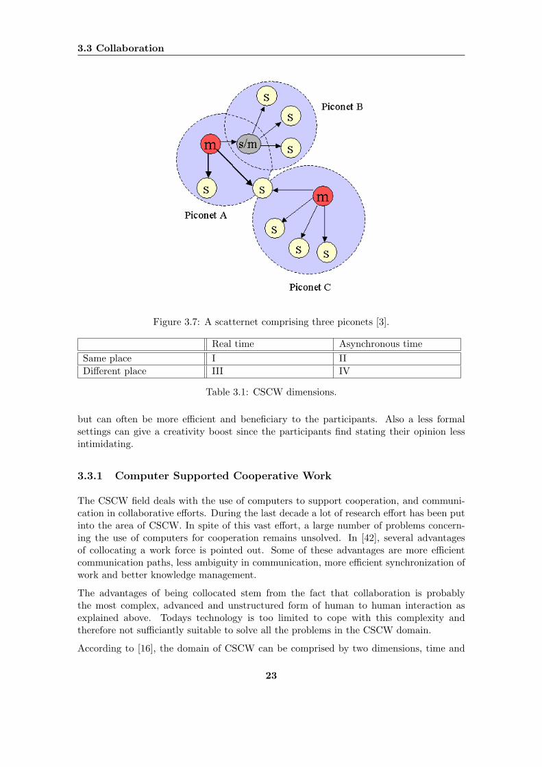
In this project we are going to focus on PANs used in collaborative applications. APAN can either be a piconet or a scatternet (see Figure 3.7). To explain the differencesbetween these to network configurations, we will take the Bluetooth PAN technology asan example. A Bluetooth piconet has a single master device and up to seven slave devices[23]. All these devices are in communication range of each other therefore all devices needonly a single network hop to communicate. The master of the piconet is the one thatinitiates the connection, and a master in one piconet can be a slave in another piconet.A device in one piconet can communicate with another device in another piconet, makingpiconets interconnecting into scatternets. Communication between nodes in a scatternetrequires advanced multihop communication. For example, a node in a scatternet mayhave to forward packets on behalf of other nodes. This functionality is not supportedin any implemented Bluetooth Application Programming Interface (API). Researchers all
21
Central Concepts
Figure 3.6: A multihop ad hoc network [1].
over the world are still working on standardizing algorithms and protocols for scatternetcommunication. In this project we will focus on communication of devices within a singlepiconet.
3.3 Collaboration
When an activity is to be carried out by more than one individuals, issues related tocommunication and synchronization emerges. This effort can be viewed as a collaborativeeffort to reach a common goal or share an experience. Human collaboration is a verycomplex natural system that we do not fully understand today. This vast complexity isdue to many contributing factors such as:
Explicit Communcation: Person-to-person communication is a thoroughly researchedfield but still a field we do not completely understand.
Contextual communcation: Much of the information exchanged between the partici-pants in a collaborative activity is of the informal type. This includes gestures, bodylanguage, ambiguity in the verbal communication due to the use of irony or sarcasm,etc.
Environment: Often the participants uses the environment for communicating, e.g. theuse of props when trying to explain a model or example.
This complexity is further expanded by the use of spontaneous and highly unstructuredcommunication paths. As an example consider the setting where to workers meet in thehallway of their office building. They stop and discuss recent advances or problems relatedto their work. This exchange is more informal than having a well planned status meeting,
22
3.3 Collaboration
Figure 3.7: A scatternet comprising three piconets [3].
Real time Asynchronous timeSame place I IIDifferent place III IV
Table 3.1: CSCW dimensions.
but can often be more efficient and beneficiary to the participants. Also a less formalsettings can give a creativity boost since the participants find stating their opinion lessintimidating.
3.3.1 Computer Supported Cooperative Work
The CSCW field deals with the use of computers to support cooperation, and communi-cation in collaborative efforts. During the last decade a lot of research effort has been putinto the area of CSCW. In spite of this vast effort, a large number of problems concern-ing the use of computers for cooperation remains unsolved. In [42], several advantagesof collocating a work force is pointed out. Some of these advantages are more efficientcommunication paths, less ambiguity in communication, more efficient synchronization ofwork and better knowledge management.
The advantages of being collocated stem from the fact that collaboration is probablythe most complex, advanced and unstructured form of human to human interaction asexplained above. Todays technology is too limited to cope with this complexity andtherefore not sufficiantly suitable to solve all the problems in the CSCW domain.
According to [16], the domain of CSCW can be comprised by two dimensions, time and
23
Central Concepts
place, as shown in Table 3.1. Most of the unsolved problems in the CSCW domain arerelated to the applications that fall into the “Different Place” category. Using CSCW ap-plications for collaboration between users that are not collocated, makes the applicationthe only communication channel used for collaboration. With this the users’ abilities tocommunicate are limited by the insufficiencies in the technologies and applications used.In the “Same Place” category, especially coupled with “Real Time” CSCW becomes moreof a support for the collaborative effort to enrich or strengthen the processes and commu-nication paths. Our framework will cover both real time and asynchronous applicationsin the “Same Place” category.
3.3.2 Mobile Computer Supported Cooperative Work
Mobile CSCW can be defined as
“Working together at variuos sites with the use of mobile IT [54].”
This means that using mobile phones or other portable devices as a platform for deployingCSCW applications places us in the domain of mobile CSCW. Today mobile phones haveseveral advantages when it comes to the area of CSCW.
Mobile phones are highly personal and most users carry their mobile phones with themat all times. This has some major implications on the use of mobile phones for CSCWpurposes:
Identification: Since the mobile phones are personal, they can be used to identify a user.
Personalization: A user can store his or her profile on the mobile phone, enabling themobile phone to function according to the user’s specific needs when interacting withother users.
Availability: Mobile phones can almost be considered to be always on, always present.Due to this, some one using their mobile phone for CSCW purposes will achieve ahigh degree of availability to other users.
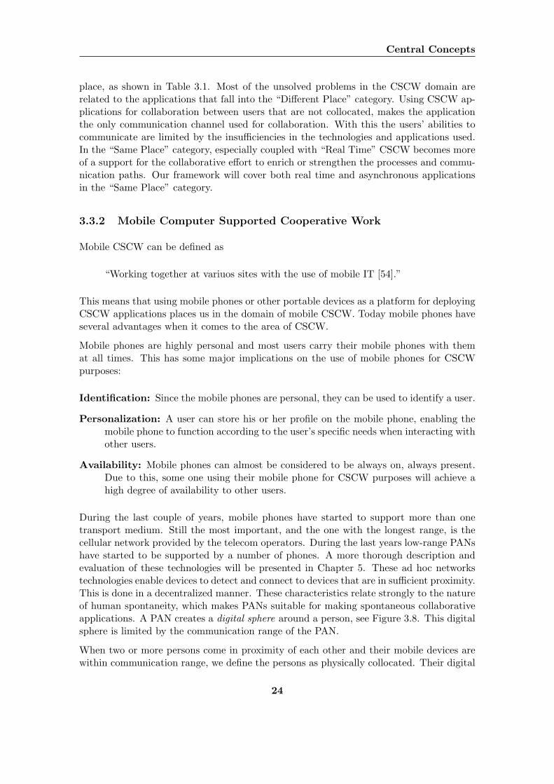
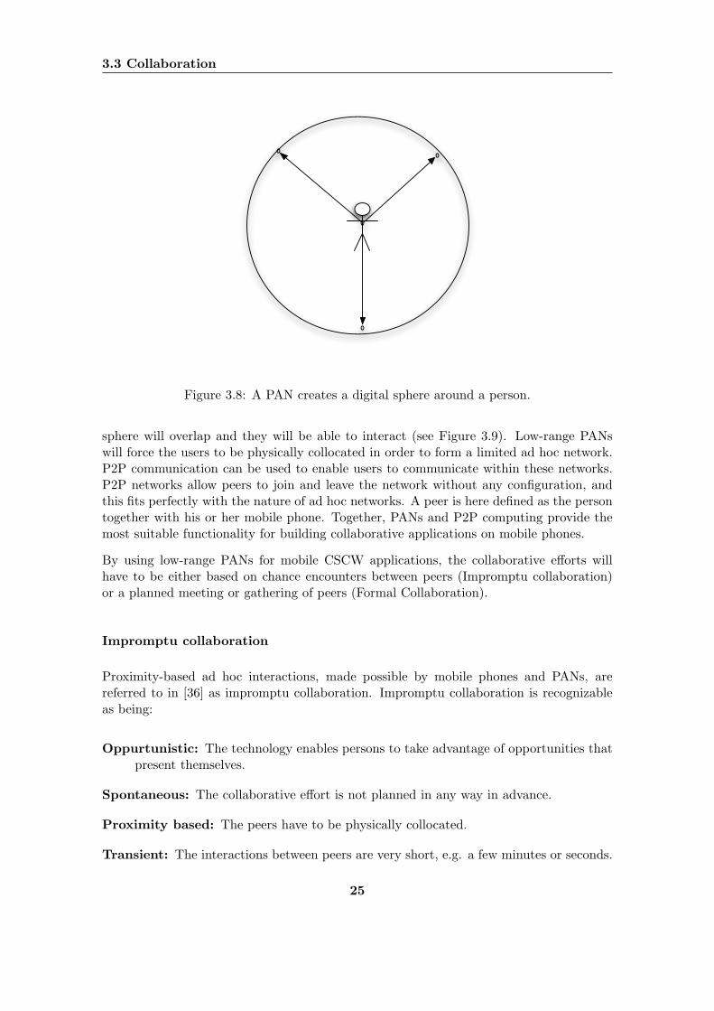
During the last couple of years, mobile phones have started to support more than onetransport medium. Still the most important, and the one with the longest range, is thecellular network provided by the telecom operators. During the last years low-range PANshave started to be supported by a number of phones. A more thorough description andevaluation of these technologies will be presented in Chapter 5. These ad hoc networkstechnologies enable devices to detect and connect to devices that are in sufficient proximity.This is done in a decentralized manner. These characteristics relate strongly to the natureof human spontaneity, which makes PANs suitable for making spontaneous collaborativeapplications. A PAN creates a digital sphere around a person, see Figure 3.8. This digitalsphere is limited by the communication range of the PAN.
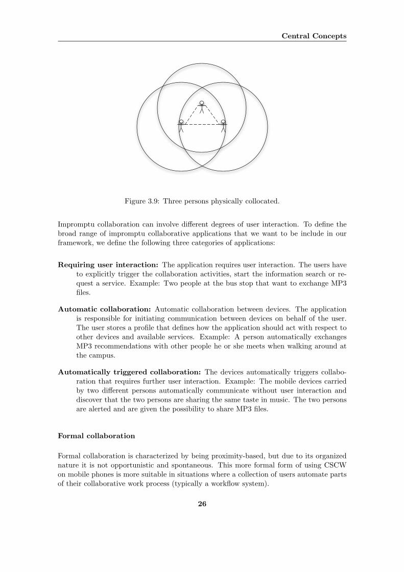
When two or more persons come in proximity of each other and their mobile devices arewithin communication range, we define the persons as physically collocated. Their digital
24
3.3 Collaboration
Figure 3.8: A PAN creates a digital sphere around a person.
sphere will overlap and they will be able to interact (see Figure 3.9). Low-range PANswill force the users to be physically collocated in order to form a limited ad hoc network.P2P communication can be used to enable users to communicate within these networks.P2P networks allow peers to join and leave the network without any configuration, andthis fits perfectly with the nature of ad hoc networks. A peer is here defined as the persontogether with his or her mobile phone. Together, PANs and P2P computing provide themost suitable functionality for building collaborative applications on mobile phones.
By using low-range PANs for mobile CSCW applications, the collaborative efforts willhave to be either based on chance encounters between peers (Impromptu collaboration)or a planned meeting or gathering of peers (Formal Collaboration).
Impromptu collaboration
Proximity-based ad hoc interactions, made possible by mobile phones and PANs, arereferred to in [36] as impromptu collaboration. Impromptu collaboration is recognizableas being:
Oppurtunistic: The technology enables persons to take advantage of opportunities thatpresent themselves.
Spontaneous: The collaborative effort is not planned in any way in advance.
Proximity based: The peers have to be physically collocated.
Transient: The interactions between peers are very short, e.g. a few minutes or seconds.
25
Central Concepts
Figure 3.9: Three persons physically collocated.
Impromptu collaboration can involve different degrees of user interaction. To define thebroad range of impromptu collaborative applications that we want to be include in ourframework, we define the following three categories of applications:
Requiring user interaction: The application requires user interaction. The users haveto explicitly trigger the collaboration activities, start the information search or re-quest a service. Example: Two people at the bus stop that want to exchange MP3files.
Automatic collaboration: Automatic collaboration between devices. The applicationis responsible for initiating communication between devices on behalf of the user.The user stores a profile that defines how the application should act with respect toother devices and available services. Example: A person automatically exchangesMP3 recommendations with other people he or she meets when walking around atthe campus.
Automatically triggered collaboration: The devices automatically triggers collabo-ration that requires further user interaction. Example: The mobile devices carriedby two different persons automatically communicate without user interaction anddiscover that the two persons are sharing the same taste in music. The two personsare alerted and are given the possibility to share MP3 files.
Formal collaboration
Formal collaboration is characterized by being proximity-based, but due to its organizednature it is not opportunistic and spontaneous. This more formal form of using CSCWon mobile phones is more suitable in situations where a collection of users automate partsof their collaborative work process (typically a workflow system).
26
3.3 Collaboration
Summary
This section has shown that low-range PANs can be suitable for collaborative applicationssince it forces the users to meet face to face in order to interact. The face to face interac-tion preserves the advantages of collocated work as described above. To further supportthe spontaneous part of mobile collaboration, the networks formed by the users as theymeet should not be dependant upon a central entity for synchronization or network/ser-vice provider. Because of this, P2P networks seem ideal for the forms of collaborationdescribed above. Interaction among humans is P2P in nature. In our everyday life, weinteract directly with each other, person-to-person, face-to-face, without the need of anintermediate, e.g. when exchanging information or doing some kind of collaborative work.Because of these facts, we argue that CSCW applications should be developed using somekind of P2P architecture.
The advantages of CSCW can be combined with those of being collocated by using alwayson, always present devices. Information is exchanged between users as they physicallymove close together, or all users are present at a meeting and the devices are used assupport to get a more efficient work process. This sets the main focus of this project. Asmentioned in Chapter 1.2, our aim is to create a framework for mobile cooperation onmobile phones using PANs as transport medium. Due to the limit range of such networks,this framework will be very suitable for applications combining collocation and CSCW.
27
Chapter 4
Related Projects
Traditionally, the main focus of research on collaboration technology has been applicationsover the Internet such as groupware, discussion boards and shared workspaces. But duringthe recent years with the emerging of mobile technology and wireless communication, therehas also been done a lot of projects concerning mobile collaboration. This section willdescribe two different categories of relevant research projects and prototypes that havebeen made, and frameworks and architectures that have been developed. An evaluation ofthese projects, including the differences between the projects and our project, is given inChapter 6. When discussing some of these projects, different kinds of Java technologies,like Java 2 Platform Standard Edition (J2SE) and Java 2 Platform Micro Edition (J2ME)are mentioned. More information on these technologies can be found in Section 5.2.
4.1 Prototypes
This section will describe different kinds of projects that have resulted in some kind ofproof-of-concept prototype. The most relevant prototype projects for our project, iCloudsand Hummingbird, will be described in more detail in separate sections. The other projectsthat we have studied will here be listed together with a short summary of each:
MobiTip: Developed at Swedish Institute of Computer Science. MobiTip is a socialmobile service where comments or tips given by one person are made available toother persons when their mobile devices connect on the fly [56]. Information canalso be stored at hot spots, and people can receive information on demand fromthese spots. The system investigate the usage of Bluetooth as a mediator of socialcontext.
Shark: Developed at the Technical University of Berlin. Shark is a distributed system,which supports organization, synchronization and exchange of knowledge for mobileusers within a given user group or between users that are members of different usergroups [46]. The system facilitates P2P exchange of arbitrary information in adhoc networks where communication links are created temporarily in a spontaneous
28
4.1 Prototypes
manner. The project also investigates how to add semantic to the information byusing standards like Topic Maps and Semantic Web. A prototype implementationof the system using Topic Maps to organize, SyncML to synchronize and the KQMLAgent-Communication Language to exchange knowledge has been developed.
Proxy Lady: Developed at the Viktoria Institute in Sweden. Proxy Lady is a prototypeof a mobile system for enabling informal, opportunistic, face-to-face communication,running on a PDA equipped with a radio transceiver [45]. The main objective ofthe system is to promote informal, opportunistic face-to-face communication. Theconcept behind Proxy Lady is that the users of the system already know each other,and store information items on their mobile devices with later interaction in mind.
The Thinking Tag: Developed at the Massachusetts Institute of Technology Media Labs.The Thinking Tags are small wearable microprocessors equipped with infrared ports,sensors, lights and a small display [37]. This project aims to develop small thinkingtags that is suppose to be more than just regular name tags providing the possibilityto add personal information. These tag should function as a support to social pro-cesses, both in formal and informal contexts, for example to serve as an icebreakerbetween strangers.
Hocman: Developed at Mobility, Interactive Institute in Sweden. This project has madea prototype system supporting mobile group collaboration among motorcyclists usingan ad hoc network [17]. The prototype has been deployed to mobile devices andtested in mobile environments. The prototype is implemented in C++ for devicesrunning the Pocket PC operating system. The design was based upon findings froma field study among motorcyclists.
4.1.1 iClouds - Peer-to-Peer Information Sharing in Mobile Environ-ments
The iClouds project1 is being developed by the Department of Computer Science at theDarmstadt University of Technology. The project group argues that the future mobile andubiquitous computing world will need new forms of information sharing and collaborationbetween people. They are currently studying the architectures and mechanisms required tosupport spontaneous mobile user interaction, collaboration and transparent data exchange.The iClouds project is a part of the more broader and general Mundo project and haveresulted in a prototype on Toshiba Pocket PC.
The motivation behind the iCloud project is described in [21] as follows:
“Whenever there is a group of people, they may share a common goal or havea related motivation. Information of interest may be in possession of only afew of them.”
The goal of the iClouds architecture is to make this information available to the wholegroup, based on individual user contribution, through P2P communications and dataexchange.
1http://iclouds.tk.informatik.tu-darmstadt.de/
29
Related Projects
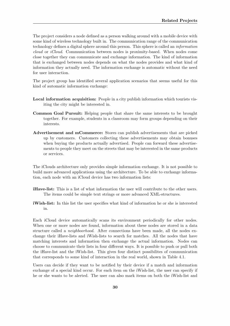
The project considers a node defined as a person walking around with a mobile device withsome kind of wireless technology built in. The communication range of the communicationtechnology defines a digital sphere around this person. This sphere is called an informationcloud or iCloud. Communication between nodes is proximity-based. When nodes comeclose together they can communicate and exchange information. The kind of informationthat is exchanged between nodes depends on what the nodes provides and what kind ofinformation they actually need. The information exchange is automatic without the needfor user interaction.
The project group has identified several application scenarios that seems useful for thiskind of automatic information exchange:
Local information acquisition: People in a city publish information which tourists vis-iting the city might be interested in.
Common Goal Pursuit: Helping people that share the same interests to be broughttogether. For example, students in a classroom may form groups depending on theirinterests.
Advertisement and mCommerce: Stores can publish advertisements that are pickedup by customers. Customers collecting these advertisements may obtain bonuseswhen buying the products actually advertised. People can forward these advertise-ments to people they meet on the streets that may be interested in the same productsor services.
The iClouds architecture only provides simple information exchange. It is not possible tobuild more advanced applications using the architecture. To be able to exchange informa-tion, each node with an iCloud device has two information lists:
iHave-list: This is a list of what information the user will contribute to the other users.The items could be simple text strings or more advanced XML-structures.
iWish-list: In this list the user specifies what kind of information he or she is interestedin.
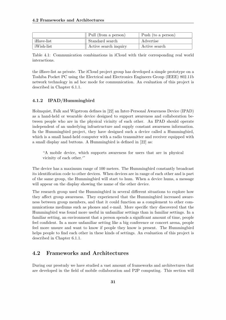
Each iCloud device automatically scans its environment periodically for other nodes.When one or more nodes are found, information about these nodes are stored in a datastructure called a neighboorhood. After connections have been made, all the nodes ex-change their iHave-lists and iWish-lists to search for matches. All the nodes that havematching interests and information then exchange the actual information. Nodes canchoose to communicate their lists in four different ways. It is possible to push or pull boththe iHave-list and the iWish-list. This gives four distinct possibilites of communicationthat corresponds to some kind of interaction in the real world, shown in Table 4.1.
Users can decide if they want to be notified by their device if a match and informationexchange of a special kind occur. For each item on the iWish-list, the user can specify ifhe or she wants to be alerted. The user can also mark items on both the iWish-list and
30
4.2 Frameworks and Architectures
Pull (from a person) Push (to a person)iHave-list Standard search AdvertiseiWish-list Active search inquiry Active search
Table 4.1: Communication combinations in iCloud with their corresponding real worldinteractions.
the iHave-list as private. The iCloud project group has developed a simple prototype on aToshiba Pocket PC using the Electrical and Electronics Engineers Group (IEEE) 802.11bnetwork technology in ad hoc mode for communication. An evaluation of this project isdescribed in Chapter 6.1.1.
4.1.2 IPAD/Hummingbird
Holmquist, Falk and Wigstrom defines in [22] an Inter-Personal Awareness Device (IPAD)as a hand-held or wearable device designed to support awareness and collaboration be-tween people who are in the physical vicinity of each other. An IPAD should operateindependent of an underlying infrastructure and supply constant awareness information.In the Hummingbird project, they have designed such a device called a Hummingbird,which is a small hand-held computer with a radio transmitter and receiver equipped witha small display and buttons. A Hummingbird is defined in [22] as:
“A mobile device, which supports awareness for users that are in physicalvicinity of each other.‘”
The device has a maximum range of 100 meters. The Hummingbird constantly broadcastits identification code to other devices. When devices are in range of each other and is partof the same group, the Hummingbird will start to hum. When a device hums, a messagewill appear on the display showing the name of the other device.
The research group used the Hummingbird in several different situations to explore howthey affect group awareness. They experienced that the Hummingbird increased aware-ness between group members, and that it could function as a complement to other com-munications mediums such as phones and e-mail. More specific they discovered that theHummingbird was found more useful in unfamiliar settings than in familiar settings. In afamiliar setting, an environment that a person spends a significant amount of time, peoplefeel confident. In a more unfamiliar setting like a big conference or concert arena, peoplefeel more unsure and want to know if people they know is present. The Hummingbirdhelps people to find each other in these kinds of settings. An evaluation of this project isdescribed in Chapter 6.1.1.
4.2 Frameworks and Architectures
During our prestudy we have studied a vast amount of frameworks and architectures thatare developed in the field of mobile collaboration and P2P computing. This section will
31
Related Projects
present the most relevant frameworks and architectures. The most relevant frameworksor architectures for our project, JXTA, JXME Proxied, JXME Proxyless, Proem andthe Spectre Framework will be described in more detail in separate sections. The otherframeworks and architectures that we have studied will here be listed together with a shortsummary:
The Anhinga project: The Anhinga project is being developed by the Department ofComputer Science at the Rochester Institute of Technology. It aims to create a dis-tributed computing infrastructure to support collaborative applications on wirelessad hoc networks [2]. It focuses on a decentralized structure and execution on mobiledevices. The architecture has been implemented and tested with example applica-tions and all the source code is available for download. The main problem, whichmakes it less relevant for our project, is that it is implemented in J2SE and will notrun on J2ME devices. J2SE and J2ME is further discussed in Chapter 5.2.1.
Jadabs: The Jadabs project is being developed by the Information and CommunicationSystems Research Group at the Swiss Federal Institute of Technology, Zurich. Themain goal is to build a dynamic framework to enable mobile devices to insert, replaceand remove applications at runtime [4]. Communication is handled by an ad hocnetwork and supports both User Datagram Protocol (UDP) and Bluetooth connec-tions. The Jadabs architecture will enable people to propagate applications moreeasily. This is not a relevant project for us, because it requires functionality onlyavailable in the CDC configuration.
PeerWare: Cugola and Picco have developed a middleware for P2P systems describedin [15]. The purpose of this middleware is to ease the development of applicationssupporting distributed and mobile cooperative work in enterprise scenarios. Themiddleware consists of a core and minimal set of primitives to support developmentof any kind of P2P application. The middleware provides fullscale P2P functions,like searching and resource management, using both proactive and reactive proto-cols. It is implemented in J2SE and is freely available for download. Because it isnot implemented in J2ME and because of its complexity, including advanced P2Pfunctionality, it is not suitable for our purpose.
A lightweight framework for ad hoc applications: A lightweight ad hoc applicationframework has been developed by Garbinato and Rupp at Universite de Lausanne,Switzerland. This framework is described in [19]. Garbinato and Rupp defines anad hoc network in terms of distance among nodes, willingness to collaborate and thedynamic features of P2P networks. They further define an ad hoc application asfollows:
“A self-organizing application composed of mobile and autonomous de-vices, interacting as peers and which relationships are made possible be-cause of relative physical distance (collocation).”
They define an ad hoc application independent of a specific underlying ad hoc net-work technology and focus on the applications aspects. A lightweight applicationframework is described. This framework is independent of any underlying ad hoc
32
4.2 Frameworks and Architectures
network technology and is based upon existing standards, like JXTA. This frame-work is too lightweight for our purpose, but introduces some interesting definitionsand thoughts.
4.2.1 JXTA
The JXTA project started as a research project at Sun Microsystems in 2001 and hasnow turned into an open source project. The project is continuously working on defininga framework for developing P2P applications. JXTA is short for Juxtapose which meansside by side. This was supposed to illustrate that P2P technology stands side by side withclient-server technology. Its goal is to explore a vision of distributed network computingusing P2P topology, and to develop basic building blocks and services that would enableinnovative applications for peer groups [6]. The most popular P2P applications such asNapster, Gnutella and ICQ, were created using different protocols, different architecturesand different implementations. Developers and scientists developing and studying P2Pcomputing are having problems communicating because of different methodologies andapproaches. Almost all applications have been built by developing its own P2P function-ality from scratch. Because of this incompatibility, the majority of today P2P applicationsare unable to cooperate and share their resources.
Because of the absence of a P2P standard, the JXTA project has received a lot of attention.JXTA is supposed to be a generic framework for developing P2P applications by providingdifferent kind of general purpose P2P protocols. According to [20], the JXTA technologyobjectives are the following:
Interoperability: JXTA technology is designed to enable interconnected peers to easilylocate each other, communicate with each other, participate in community-basedactivities and offer services to each other seamlessly across different P2P systemsand different communities.
Platform independence: JXTA technology is designed to be independent of program-ming languages (such as C or the Java programming language), system platforms(such as Microsoft Windows and UNIX operating systems) and networking platforms(such as TCP/IP or Bluetooth).
Ubiquity: JXTA technology is designed to be implementable on every device with a dig-ital heartbeat, including sensors, consumer electronics, PDAs, appliances, networkrouters, desktop computers, data-center servers and storage systems.
The framework introduces a terminology for defining entities in a P2P system. A peeris any networked device that implements one or more of the JXTA protocols. Peerscan be collected in a peer group and communicate through a connection called a pipe.The transport protocol of this connection is not defined in the framework. All entitiesare described by advertisements, written as XML structured documents, and all entitiescommunicate by sending messages to each other.
33
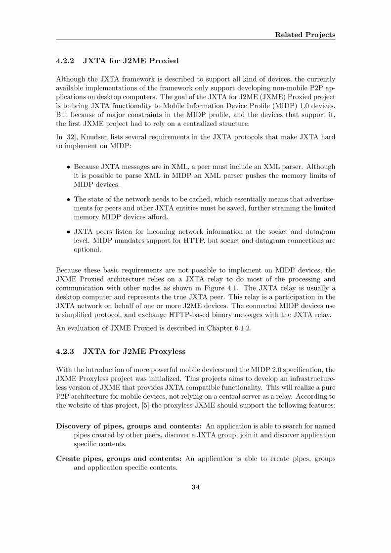
Related Projects
4.2.2 JXTA for J2ME Proxied
Although the JXTA framework is described to support all kind of devices, the currentlyavailable implementations of the framework only support developing non-mobile P2P ap-plications on desktop computers. The goal of the JXTA for J2ME (JXME) Proxied projectis to bring JXTA functionality to Mobile Information Device Profile (MIDP) 1.0 devices.But because of major constraints in the MIDP profile, and the devices that support it,the first JXME project had to rely on a centralized structure.
In [32], Knudsen lists several requirements in the JXTA protocols that make JXTA hardto implement on MIDP:
• Because JXTA messages are in XML, a peer must include an XML parser. Althoughit is possible to parse XML in MIDP an XML parser pushes the memory limits ofMIDP devices.
• The state of the network needs to be cached, which essentially means that advertise-ments for peers and other JXTA entities must be saved, further straining the limitedmemory MIDP devices afford.
• JXTA peers listen for incoming network information at the socket and datagramlevel. MIDP mandates support for HTTP, but socket and datagram connections areoptional.
Because these basic requirements are not possible to implement on MIDP devices, theJXME Proxied architecture relies on a JXTA relay to do most of the processing andcommunication with other nodes as shown in Figure 4.1. The JXTA relay is usually adesktop computer and represents the true JXTA peer. This relay is a participation in theJXTA network on behalf of one or more J2ME devices. The connected MIDP devices usea simplified protocol, and exchange HTTP-based binary messages with the JXTA relay.
An evaluation of JXME Proxied is described in Chapter 6.1.2.
4.2.3 JXTA for J2ME Proxyless
With the introduction of more powerful mobile devices and the MIDP 2.0 specification, theJXME Proxyless project was initialized. This projects aims to develop an infrastructure-less version of JXME that provides JXTA compatible functionality. This will realize a pureP2P architecture for mobile devices, not relying on a central server as a relay. According tothe website of this project, [5] the proxyless JXME should support the following features:
Discovery of pipes, groups and contents: An application is able to search for namedpipes created by other peers, discover a JXTA group, join it and discover applicationspecific contents.
Create pipes, groups and contents: An application is able to create pipes, groupsand application specific contents.
34
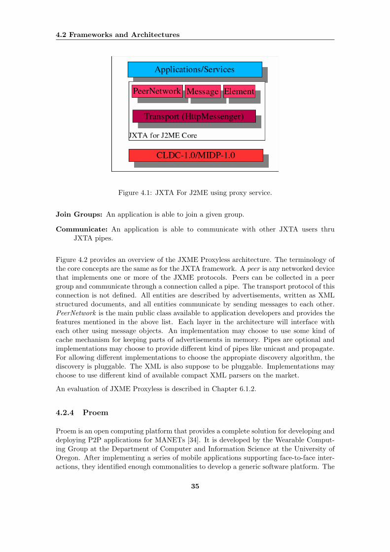
4.2 Frameworks and Architectures
Figure 4.1: JXTA For J2ME using proxy service.
Join Groups: An application is able to join a given group.
Communicate: An application is able to communicate with other JXTA users thruJXTA pipes.
Figure 4.2 provides an overview of the JXME Proxyless architecture. The terminology ofthe core concepts are the same as for the JXTA framework. A peer is any networked devicethat implements one or more of the JXME protocols. Peers can be collected in a peergroup and communicate through a connection called a pipe. The transport protocol of thisconnection is not defined. All entities are described by advertisements, written as XMLstructured documents, and all entities communicate by sending messages to each other.PeerNetwork is the main public class available to application developers and provides thefeatures mentioned in the above list. Each layer in the architecture will interface witheach other using message objects. An implementation may choose to use some kind ofcache mechanism for keeping parts of advertisements in memory. Pipes are optional andimplementations may choose to provide different kind of pipes like unicast and propagate.For allowing different implementations to choose the appropiate discovery algorithm, thediscovery is pluggable. The XML is also suppose to be pluggable. Implementations maychoose to use different kind of available compact XML parsers on the market.
An evaluation of JXME Proxyless is described in Chapter 6.1.2.
4.2.4 Proem
Proem is an open computing platform that provides a complete solution for developing anddeploying P2P applications for MANETs [34]. It is developed by the Wearable Comput-ing Group at the Department of Computer and Information Science at the University ofOregon. After implementing a series of mobile applications supporting face-to-face inter-actions, they identified enough commonalities to develop a generic software platform. The
35
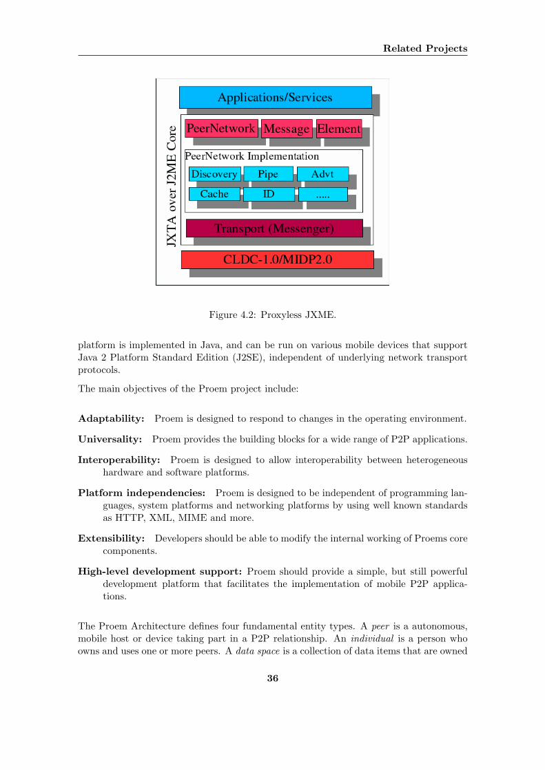
Related Projects
Figure 4.2: Proxyless JXME.
platform is implemented in Java, and can be run on various mobile devices that supportJava 2 Platform Standard Edition (J2SE), independent of underlying network transportprotocols.
The main objectives of the Proem project include:
Adaptability: Proem is designed to respond to changes in the operating environment.
Universality: Proem provides the building blocks for a wide range of P2P applications.
Interoperability: Proem is designed to allow interoperability between heterogeneoushardware and software platforms.
Platform independencies: Proem is designed to be independent of programming lan-guages, system platforms and networking platforms by using well known standardsas HTTP, XML, MIME and more.
Extensibility: Developers should be able to modify the internal working of Proems corecomponents.
High-level development support: Proem should provide a simple, but still powerfuldevelopment platform that facilitates the implementation of mobile P2P applica-tions.
The Proem Architecture defines four fundamental entity types. A peer is a autonomous,mobile host or device taking part in a P2P relationship. An individual is a person whoowns and uses one or more peers. A data space is a collection of data items that are owned
36
4.2 Frameworks and Architectures
and managed by a set of peers. A community is a a set of entities and each entities can bea member of several communities. Entities are identified by names expressed by UniformResource Identifiers. Entities can also be indirectly identified by profiles. A profile is anXML-based data structure for describing Proem entities. An evaluation of The ProemArchitecture is described in Chapter 6.1.2.
4.2.5 The Spectre Framework
This section introduces the work, from related projects done by Anders Rene Sveen andLars Kirkhus during 2003 and 2004, that ended up with a design for collaborative appli-cations on mobile phones.
During the fall of 2003 Sveen and Kirkhus worked on a project where they examinedavailable technologies for spontaneous collaboration [29]. The conclusion drawn was thatthe optimal solution with the available technology was an implementation on Java 2 MicroEdition (J2ME) for mobile phones using Bluetooth as transport medium. This projectlaid down the foundation for the Spectre Framework.
In [30], Sveen and Kirkhus present a design for a generic framework for mobile collabo-ration applications called the Spectre Framework. The design is based on five differentscenarios for collaborative applications using mobile phones and the requirements gatheredare verified to fit the given scenarios. The scenarios vary from simple PAN communicationbetween only two devices to advanced multihop P2P communication. The framework isdesigned to be as generic as possible to fit a varied set of applications and to ease thetransition to other transport layers.
The main package structure of the Spectre Framework is shown in Figure 4.3. The domainholds information about nodes, groups and data types and is shared and used by alllayers of the framework. A node represents a physical device that is running at least oneinstance of the framework. A group is an representation of all nodes that participate in ancollaborative activity. Applications that run upon the Spectre framework will offer one ormore services. The framework provides an application interface where the application asksthe framework to perform actions. The transport interface is responsible for doing the lowlevel communication with other devices. The framework is abstracted from the underlyingtransport technology for easy deployment of applications with different transport mediums.An evaluation of the Spectre Framework is described in Chapter 6.1.2.
37
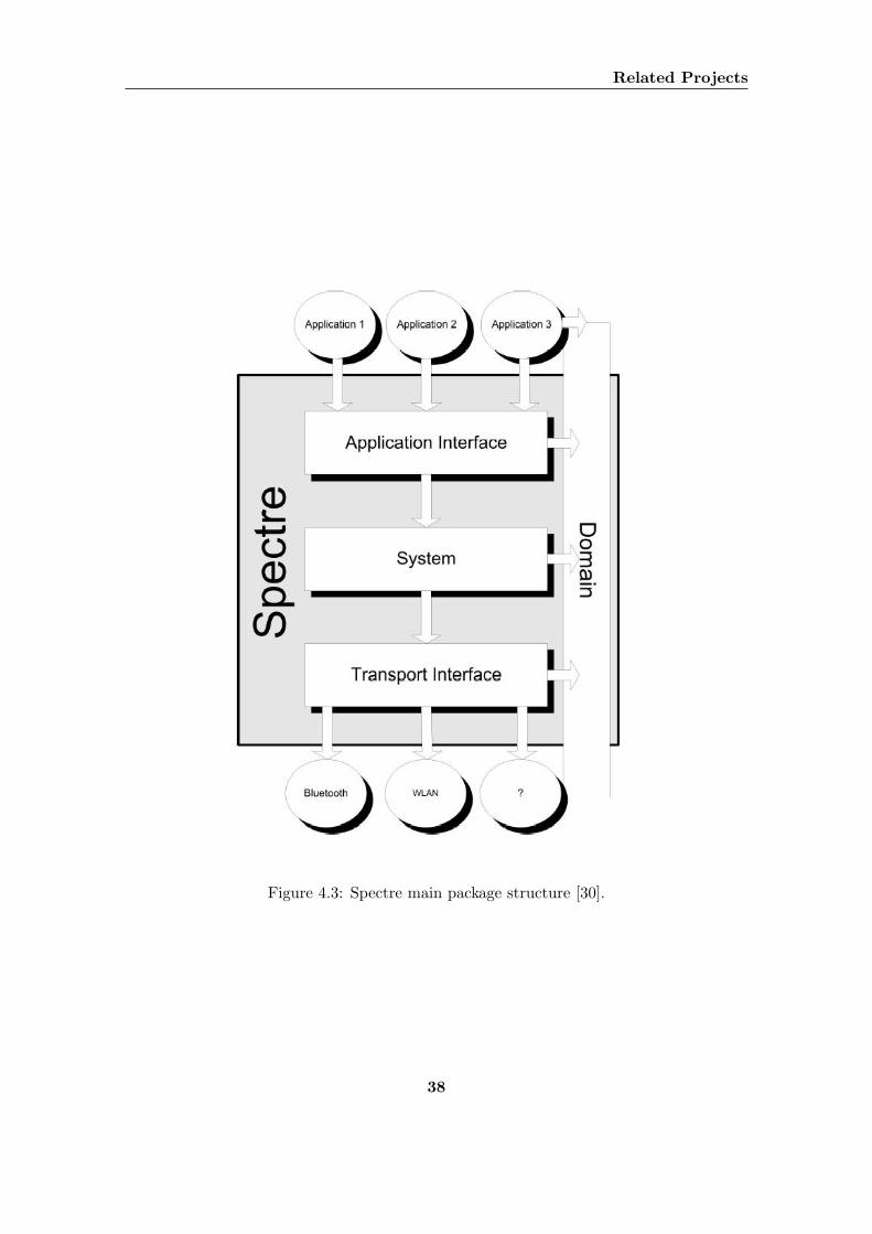
Related Projects
Figure 4.3: Spectre main package structure [30].
38
Chapter 5
New Technology
An extensive technology study was performed through the reports [30] and [29]. Duringthe last half year, several advances has been made in the field of wireless communica-tion devices and technologies. The conclusions drawn in the formerly mentioned reports,though valid at the time, may have been invalidated by the introduction new technologies.In this chapter we will discuss and evaluate the advances made during the last 6 monthsand compare them with the results from [30] and [29].
The evaluation technique used will be the same as in [30]. We will only do a brief summaryof it here. In addition to the evaluation points used in [30], we will also consider securityaspects.
All evaluated technologies will be graded with respect to spread, transparency, mobilityand wether or not it is non-centralised. The different evaluation criteria are interpretedas:
Spread: Measures the technology’s potential for high availability.
Transparency: Measures in what degree the user has to acquire new skills in order touse the proposed technology.
Mobility: Measures the technology ability to be used on a mobile platform to increasethe size of the potential user base.
Non-centralised network: Measures wether the technology is dependant on a centralprocessing server to function.
Security: Measures the reliability of the technology with respect to hostile third parties.
Each criteria is given a weight from 0 to 5, where 0 means that the criteria is irrelevantto this project and 5 means it is of the highest importance.
For each criteria we will give a grade between 0 and 5, where 0 means the technology isnot suited for our use and 5 means it is very highly suited.
39
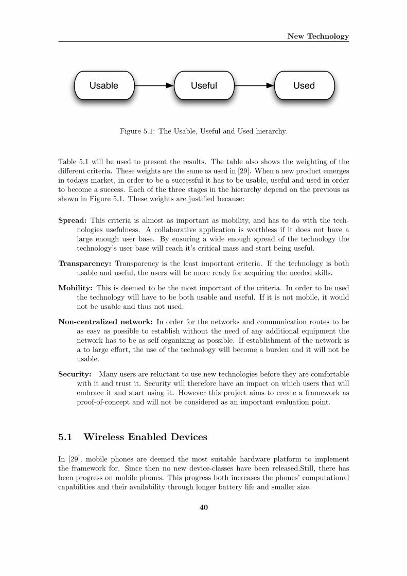
New Technology
Usable Useful Used
Figure 5.1: The Usable, Useful and Used hierarchy.
Table 5.1 will be used to present the results. The table also shows the weighting of thedifferent criteria. These weights are the same as used in [29]. When a new product emergesin todays market, in order to be a successful it has to be usable, useful and used in orderto become a success. Each of the three stages in the hierarchy depend on the previous asshown in Figure 5.1. These weights are justified because:
Spread: This criteria is almost as important as mobility, and has to do with the tech-nologies usefulness. A collabarative application is worthless if it does not have alarge enough user base. By ensuring a wide enough spread of the technology thetechnology’s user base will reach it’s critical mass and start being useful.
Transparency: Transparency is the least important criteria. If the technology is bothusable and useful, the users will be more ready for acquiring the needed skills.
Mobility: This is deemed to be the most important of the criteria. In order to be usedthe technology will have to be both usable and useful. If it is not mobile, it wouldnot be usable and thus not used.
Non-centralized network: In order for the networks and communication routes to beas easy as possible to establish without the need of any additional equipment thenetwork has to be as self-organizing as possible. If establishment of the network isa to large effort, the use of the technology will become a burden and it will not beusable.
Security: Many users are reluctant to use new technologies before they are comfortablewith it and trust it. Security will therefore have an impact on which users that willembrace it and start using it. However this project aims to create a framework asproof-of-concept and will not be considered as an important evaluation point.
5.1 Wireless Enabled Devices
In [29], mobile phones are deemed the most suitable hardware platform to implementthe framework for. Since then no new device-classes have been released.Still, there hasbeen progress on mobile phones. This progress both increases the phones’ computationalcapabilities and their availability through longer battery life and smaller size.
40
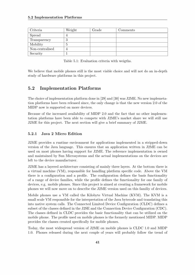
5.2 Implementation Platforms
Criteria Weight Grade CommentsSpread 4Transparency 3Mobility 5Non-centralised 4Security 1
Table 5.1: Evaluation criteria with weigths.
We believe that mobile phones still is the most viable choice and will not do an in-depthstudy of hardware platforms in this project.
5.2 Implementation Platforms
The choice of implementation platform done in [29] and [30] was J2ME. No new implemeta-tion platforms have been released since, the only change is that the new version 2.0 of theMIDP now is supported on more devices.
Because of the increased availability of MIDP 2.0 and the fact that no other implemen-tation platforms have been able to compete with J2ME’s market share we will still useJ2ME for this project. The next section will give a brief summary of J2ME.
5.2.1 Java 2 Micro Edition
J2ME provides a runtime environment for applications implemented in a stripped-downversion of the Java language. This ensures that an application written in J2ME can beused on most phones having support for J2ME. The reference implementation is ownedand maintained by Sun Microsystems and the actual implementations on the devices areleft to the device manufacturer.
J2ME has a layered architecture consisting of mainly three layers. At the bottom there isa virtual machine (VM), responsible for handling platform specific code. Above the VMthere is a configuration and a profile. The configuration defines the basis functionalityof a range of device families, while the profile defines the functionality for one family ofdevices, e.g. mobile phones. Since this project is aimed at creating a framework for mobilephones we will now move on to describe the J2ME version used on this familiy of devices.
Mobile phones use a VM called the Kilobyte Virtual Machine (KVM). The KVM is asmall scale VM responsible for the interpretation of the Java bytecode and translating thisinto native system calls. The Connected Limited Device Configuration (CLDC) defines asubset of the classes defined in the J2SE and the Connection Device Configuration (CDC).The classes defined in CLDC provides the basic functionality that can be utilized on themobile phone. The profile used on mobile phones is the formerly mentioned MIDP. MIDPprovides the classes created specifically for mobile phones.
Today, the most widespread version of J2ME on mobile phones is CLDC 1.0 and MIDP1.0. Phones released during the next couple of years will probably follow the trend of
41
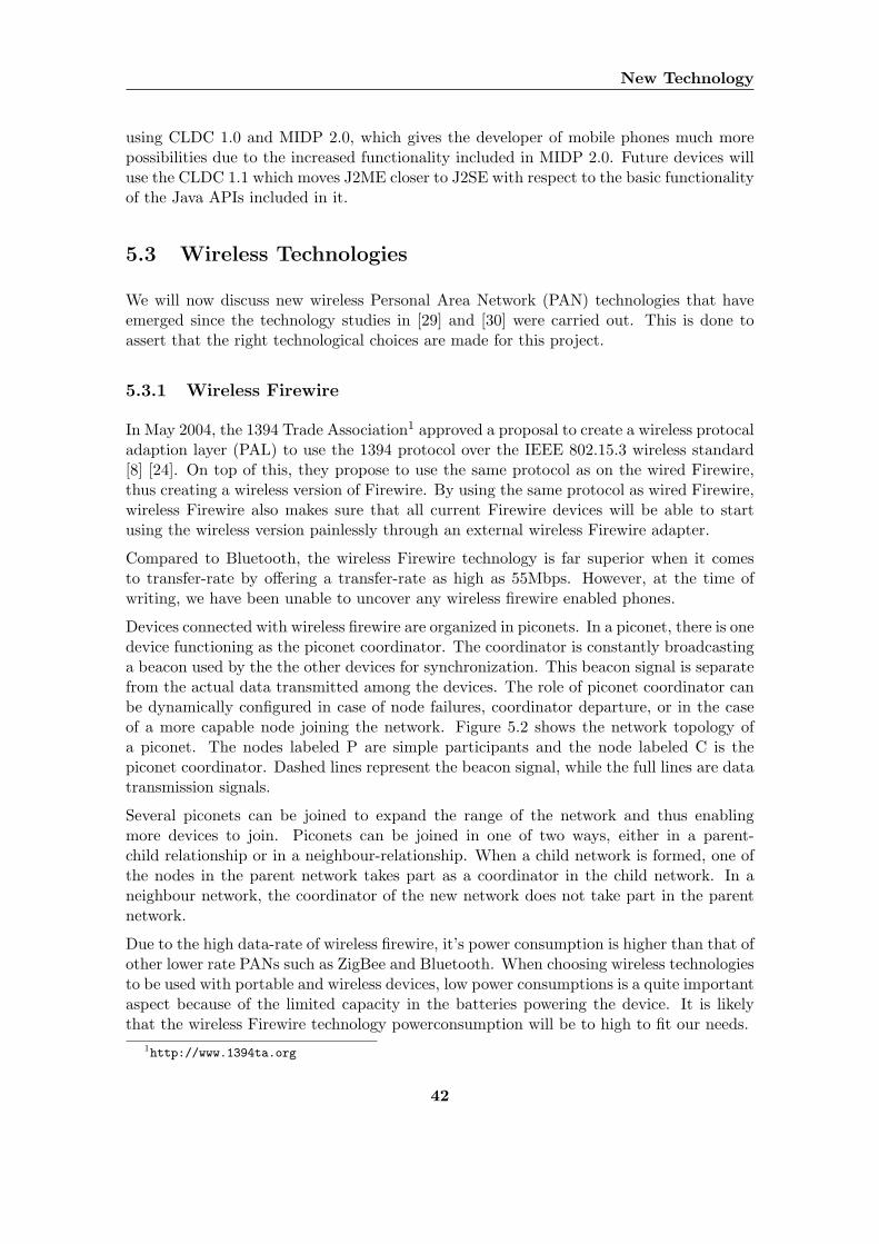
New Technology
using CLDC 1.0 and MIDP 2.0, which gives the developer of mobile phones much morepossibilities due to the increased functionality included in MIDP 2.0. Future devices willuse the CLDC 1.1 which moves J2ME closer to J2SE with respect to the basic functionalityof the Java APIs included in it.
5.3 Wireless Technologies
We will now discuss new wireless Personal Area Network (PAN) technologies that haveemerged since the technology studies in [29] and [30] were carried out. This is done toassert that the right technological choices are made for this project.
5.3.1 Wireless Firewire
In May 2004, the 1394 Trade Association1 approved a proposal to create a wireless protocaladaption layer (PAL) to use the 1394 protocol over the IEEE 802.15.3 wireless standard[8] [24]. On top of this, they propose to use the same protocol as on the wired Firewire,thus creating a wireless version of Firewire. By using the same protocol as wired Firewire,wireless Firewire also makes sure that all current Firewire devices will be able to startusing the wireless version painlessly through an external wireless Firewire adapter.
Compared to Bluetooth, the wireless Firewire technology is far superior when it comesto transfer-rate by offering a transfer-rate as high as 55Mbps. However, at the time ofwriting, we have been unable to uncover any wireless firewire enabled phones.
Devices connected with wireless firewire are organized in piconets. In a piconet, there is onedevice functioning as the piconet coordinator. The coordinator is constantly broadcastinga beacon used by the the other devices for synchronization. This beacon signal is separatefrom the actual data transmitted among the devices. The role of piconet coordinator canbe dynamically configured in case of node failures, coordinator departure, or in the caseof a more capable node joining the network. Figure 5.2 shows the network topology ofa piconet. The nodes labeled P are simple participants and the node labeled C is thepiconet coordinator. Dashed lines represent the beacon signal, while the full lines are datatransmission signals.
Several piconets can be joined to expand the range of the network and thus enablingmore devices to join. Piconets can be joined in one of two ways, either in a parent-child relationship or in a neighbour-relationship. When a child network is formed, one ofthe nodes in the parent network takes part as a coordinator in the child network. In aneighbour network, the coordinator of the new network does not take part in the parentnetwork.
Due to the high data-rate of wireless firewire, it’s power consumption is higher than that ofother lower rate PANs such as ZigBee and Bluetooth. When choosing wireless technologiesto be used with portable and wireless devices, low power consumptions is a quite importantaspect because of the limited capacity in the batteries powering the device. It is likelythat the wireless Firewire technology powerconsumption will be to high to fit our needs.
1http://www.1394ta.org
42
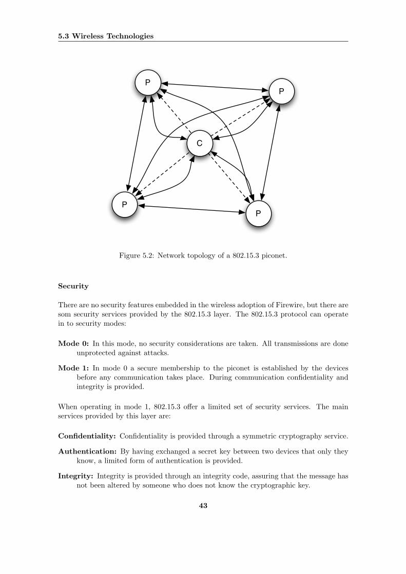
5.3 Wireless Technologies
C
P
P
P
P
Figure 5.2: Network topology of a 802.15.3 piconet.
Security
There are no security features embedded in the wireless adoption of Firewire, but there aresom security services provided by the 802.15.3 layer. The 802.15.3 protocol can operatein to security modes:
Mode 0: In this mode, no security considerations are taken. All transmissions are doneunprotected against attacks.
Mode 1: In mode 0 a secure membership to the piconet is established by the devicesbefore any communication takes place. During communication confidentiality andintegrity is provided.
When operating in mode 1, 802.15.3 offer a limited set of security services. The mainservices provided by this layer are:
Confidentiality: Confidentiality is provided through a symmetric cryptography service.
Authentication: By having exchanged a secret key between two devices that only theyknow, a limited form of authentication is provided.
Integrity: Integrity is provided through an integrity code, assuring that the message hasnot been altered by someone who does not know the cryptographic key.
43
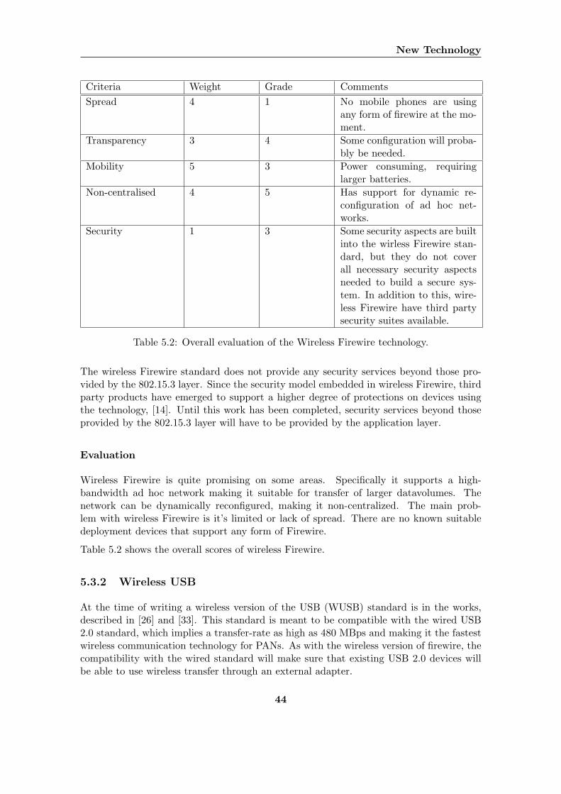
New Technology
Criteria Weight Grade CommentsSpread 4 1 No mobile phones are using
any form of firewire at the mo-ment.
Transparency 3 4 Some configuration will proba-bly be needed.
Mobility 5 3 Power consuming, requiringlarger batteries.
Non-centralised 4 5 Has support for dynamic re-configuration of ad hoc net-works.
Security 1 3 Some security aspects are builtinto the wirless Firewire stan-dard, but they do not coverall necessary security aspectsneeded to build a secure sys-tem. In addition to this, wire-less Firewire have third partysecurity suites available.
Table 5.2: Overall evaluation of the Wireless Firewire technology.
The wireless Firewire standard does not provide any security services beyond those pro-vided by the 802.15.3 layer. Since the security model embedded in wireless Firewire, thirdparty products have emerged to support a higher degree of protections on devices usingthe technology, [14]. Until this work has been completed, security services beyond thoseprovided by the 802.15.3 layer will have to be provided by the application layer.
Evaluation
Wireless Firewire is quite promising on some areas. Specifically it supports a high-bandwidth ad hoc network making it suitable for transfer of larger datavolumes. Thenetwork can be dynamically reconfigured, making it non-centralized. The main prob-lem with wireless Firewire is it’s limited or lack of spread. There are no known suitabledeployment devices that support any form of Firewire.
Table 5.2 shows the overall scores of wireless Firewire.
5.3.2 Wireless USB
At the time of writing a wireless version of the USB (WUSB) standard is in the works,described in [26] and [33]. This standard is meant to be compatible with the wired USB2.0 standard, which implies a transfer-rate as high as 480 MBps and making it the fastestwireless communication technology for PANs. As with the wireless version of firewire, thecompatibility with the wired standard will make sure that existing USB 2.0 devices willbe able to use wireless transfer through an external adapter.
44
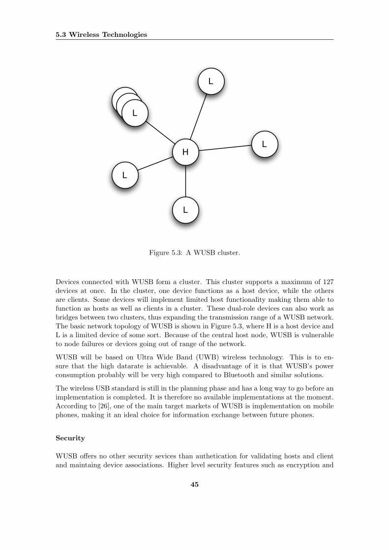
5.3 Wireless Technologies
HL
L
L
L
L
Figure 5.3: A WUSB cluster.
Devices connected with WUSB form a cluster. This cluster supports a maximum of 127devices at once. In the cluster, one device functions as a host device, while the othersare clients. Some devices will implement limited host functionality making them able tofunction as hosts as well as clients in a cluster. These dual-role devices can also work asbridges between two clusters, thus expanding the transmission range of a WUSB network.The basic network topology of WUSB is shown in Figure 5.3, where H is a host device andL is a limited device of some sort. Because of the central host node, WUSB is vulnerableto node failures or devices going out of range of the network.
WUSB will be based on Ultra Wide Band (UWB) wireless technology. This is to en-sure that the high datarate is achievable. A disadvantage of it is that WUSB’s powerconsumption probably will be very high compared to Bluetooth and similar solutions.
The wireless USB standard is still in the planning phase and has a long way to go before animplementation is completed. It is therefore no available implementations at the moment.According to [26], one of the main target markets of WUSB is implementation on mobilephones, making it an ideal choice for information exchange between future phones.
Security
WUSB offers no other security sevices than authetication for validating hosts and clientand maintaing device associations. Higher level security features such as encryption and
45
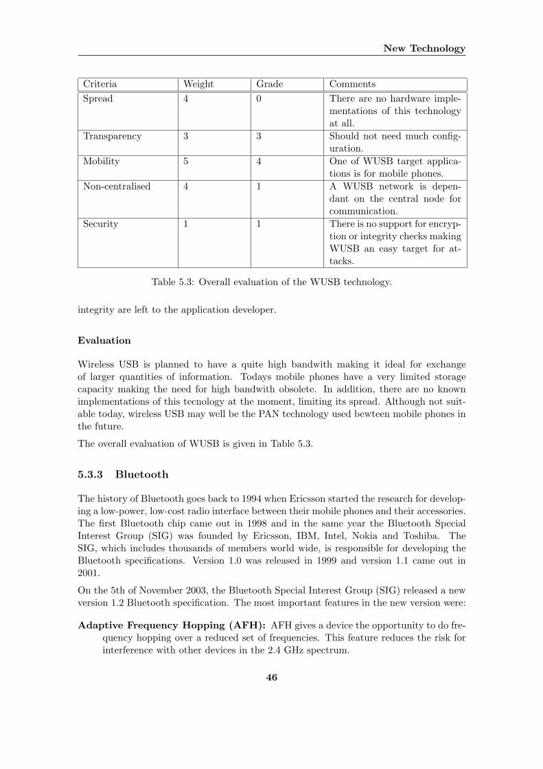
New Technology
Criteria Weight Grade CommentsSpread 4 0 There are no hardware imple-
mentations of this technologyat all.
Transparency 3 3 Should not need much config-uration.
Mobility 5 4 One of WUSB target applica-tions is for mobile phones.
Non-centralised 4 1 A WUSB network is depen-dant on the central node forcommunication.
Security 1 1 There is no support for encryp-tion or integrity checks makingWUSB an easy target for at-tacks.
Table 5.3: Overall evaluation of the WUSB technology.
integrity are left to the application developer.
Evaluation
Wireless USB is planned to have a quite high bandwith making it ideal for exchangeof larger quantities of information. Todays mobile phones have a very limited storagecapacity making the need for high bandwith obsolete. In addition, there are no knownimplementations of this tecnology at the moment, limiting its spread. Although not suit-able today, wireless USB may well be the PAN technology used bewteen mobile phones inthe future.
The overall evaluation of WUSB is given in Table 5.3.
5.3.3 Bluetooth
The history of Bluetooth goes back to 1994 when Ericsson started the research for develop-ing a low-power, low-cost radio interface between their mobile phones and their accessories.The first Bluetooth chip came out in 1998 and in the same year the Bluetooth SpecialInterest Group (SIG) was founded by Ericsson, IBM, Intel, Nokia and Toshiba. TheSIG, which includes thousands of members world wide, is responsible for developing theBluetooth specifications. Version 1.0 was released in 1999 and version 1.1 came out in2001.
On the 5th of November 2003, the Bluetooth Special Interest Group (SIG) released a newversion 1.2 Bluetooth specification. The most important features in the new version were:
Adaptive Frequency Hopping (AFH): AFH gives a device the opportunity to do fre-quency hopping over a reduced set of frequencies. This feature reduces the risk forinterference with other devices in the 2.4 GHz spectrum.
46
5.3 Wireless Technologies
Enhanced voice processing: Improvement of sound quality in noisy environments us-ing different kinds of error detection methods.
Faster connection setup: Reducing the time for setting up connections between de-vices.
Backwards compatibility: The new specification is backward compatible with version1.1.
At the 2004 Wireless Connectivity show in Amsterdam, the Bluetooth SIG announced anew prototype specification named Enhanced Data Rate (EDR) [48]. The new specifica-tion will provide three times faster data transmission. This is obtained by using a differentmodulation technique. All current Bluetooth radios use a modulation technique known asGaussian Frequency Shift Keying (GFSK) allowing a practical transmission speed of 721Kbps. EDR transmissions use a different modulation technique, called Phase Shift Key-ing (PSK), which gives the ability to transfer data at rates up to 2.1 Mbps [47]. Becausethese changes is implemented in the link manager controller it does not affect higher layerprotocols, making the EDR backwards compatible with all previous specifications.
The increased data rate has several implications on the uses of Bluetooth:
• Lower power consumption because of faster transmissions.
• Enhanced possibilites for using several devices simultaneously because of more avail-able bandwidth.
• Enable new applications that requires up to 2 Mbps.
The Bluetooth SIG expects the EDR specification to be finalized in fall 2004, with productsbased upon the specification available in 2005 [48].
Security
The Bluetooth security architecture is best described by its three modes. One device canonly operate in one mode at a time. The three different security modes are the following[52]:
Security Mode 1: A non-secure mode
Security Mode 2: Security on service level
Security Mode 3: Security on link level
In Security Mode 1, all security functionality is bypassed. In this mode the device allowsother devices to connect to it without any form of authentication or encryption. This modeis suitable for applications for which security is not an issue. In Security Mode 2 a securitymanager in the Bluetooth architecture provides access control to services and devices.After a channel is set up security is established above the link level providing the possibility
47
New Technology
for different security for different applications. This service is called authorization andaddresses the question Has this device been authorized to use this service?. In SecurityMode 3, all the involved devices initiate security at the link level before a channel isestablished. This security is totally transparent for the application layer. The modeprovides encryption and authentication based upon a secret key, which is generated duringa pairing procedure between the devices. This pairing procedure involves an identical PIN-code entry from the users.
In addition to the three security modes, Bluetooth allows two levels of trust, trusted anduntrusted. In addition it provides three levels of service security [28]:
Service Level 1: Both authorization and authentication
Service Level 2: Authentication only
Service Level 3: No authentication and no authorization
In addition to its security architecture, Bluetooth provides a special kind of security byits nature. Bluetooth operates in the 2.4 GHz spectrum and utilises frequence hopping,with 1600 hops per second, between 79 separate channels in a 83.5 MHz wide band. In aBluetooth piconet, all devices have to be synchronized with the master device to be ableto communicate. This means that each pair of connected devices needs to be synchronizedand share a common hopping frequence. This reduces the possibilites for eavesdropping,an attacker listing to the transmission between to devices, because an attacker has to findthe right channel and hopping frequence to be able to eavesdrop.
Still there are some known vulnerabilities in the Bluetooth security architecture:
• Short PIN-codes are allowed, makes encryption and authentication weaker
• Audit, nonrepudation and other services do not exist, have to be built upon thesecurity architecture
• No user authentication exists
• Private keys used in enryption and authentication are being reused and thereforebecome public
• Possible man-in-the-middle attack
Because the security architecture above supports no end-to-end security, Bluetooth appli-cations on different devices may have major security flaws. End of November 2003 Adamand Ben Laurie published a document [38] stating that some Bluetooth-enabled mobilephones are having serious security flaws. The three most critical vulnerabilities that werefound are the following:
The SNARF attack: Confidential data can be obtained, anonymously, and without theowner’s knowledge or consent.
48
5.3 Wireless Technologies
The BACKDOOR attack: Complete memory contents of some mobile phones can beaccessed by a previuosly trusted device that has since been removed from the trustedlist.
The BLUEBUG attack: Access can be gained to the AT command set of the device,giving full access to the higher level commands and channels, such as data, voiceand messaging.
The above vulnerabilites is exploited by techniques called Bluejacking, Bluesnarfing andBluebugging. All these vulnerabilties, and also the techniques for exploiting them, harmsthe popularity of Bluetooth and illustrates the difficulties regarding security when makingmobile applications.
Evaluation
Bluetooth is no doubt the most widespread PAN technology. In June 2004, IMS research2
annonuced that weekly sales of Bluetooth enabled devices had reached 2 millions. Threemonths later, in september 2004, the number of devices sold each week has increasedto 3 million devices. More than 3000 manufactures provides the consumer market withBluetooth enabled products. From being just a simple PAN technology mainly targeted forthe consumer market, Bluetooth is now also being used in totally new areas like medicinand logistics.
Since its first realease in 1998, the technology has become more mature, mainly becauseof having a large organization, the Bluetooth SIG, constantly working on improving anddeveloping new specifications. The technology is easy to use and has mature APIs pro-viding support for multiple connections, service discovery and device discovery. Bluetoothhas a very low power consumption because using a very low transmission power of about2.5 mW. It is possible to integrate the technology into small mobile devices. The overallevaluation of Bluetooth is given in Table 5.4.
5.3.4 ZigBee
ZigBee is a new wireless standard based on the IEEE 802.15.4 specification for wirelessPANS, [25]. It was initially designed as a process and control network aimed at controllerdevices such as stereo-remotes or devices for wireless control of medical equipment.
The datarate achieved when using ZigBee for wireless transfer is as low as 250 Kbps.
When connecting ZigBee devices, their functionality and network topology are quite sim-ilar to that of WUSB and Bluetooth. All connected devices are arranged into either Starnetworks, Meshes or Cluster Trees. Of the three, the Star network is the least powercon-suming, where one device functions as the PAN coordinator. Meshes employ a form ofP2P topology where other fully functinal devices can work as a bridge between a deviceon the edge of the network and the coordinator. Cluster Trees are crosses of Star and
2http://www.imsresearch.com/
49
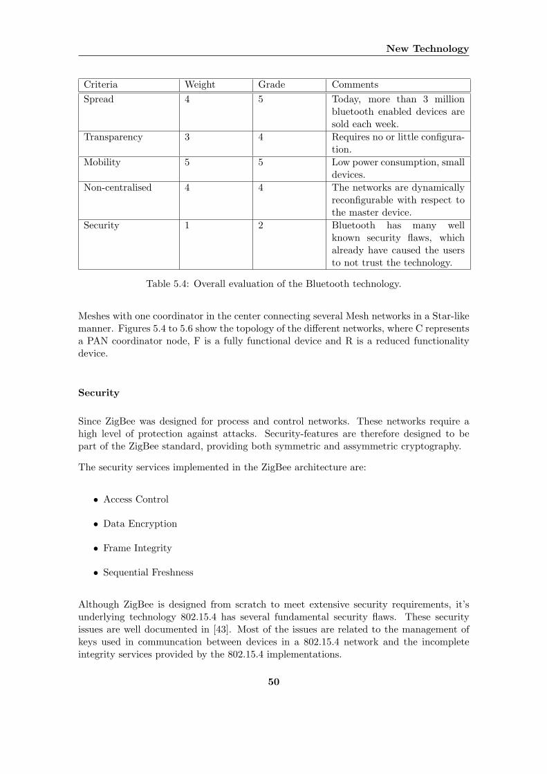
New Technology
Criteria Weight Grade CommentsSpread 4 5 Today, more than 3 million
bluetooth enabled devices aresold each week.
Transparency 3 4 Requires no or little configura-tion.
Mobility 5 5 Low power consumption, smalldevices.
Non-centralised 4 4 The networks are dynamicallyreconfigurable with respect tothe master device.
Security 1 2 Bluetooth has many wellknown security flaws, whichalready have caused the usersto not trust the technology.
Table 5.4: Overall evaluation of the Bluetooth technology.
Meshes with one coordinator in the center connecting several Mesh networks in a Star-likemanner. Figures 5.4 to 5.6 show the topology of the different networks, where C representsa PAN coordinator node, F is a fully functional device and R is a reduced functionalitydevice.
Security
Since ZigBee was designed for process and control networks. These networks require ahigh level of protection against attacks. Security-features are therefore designed to bepart of the ZigBee standard, providing both symmetric and assymmetric cryptography.
The security services implemented in the ZigBee architecture are:
• Access Control
• Data Encryption
• Frame Integrity
• Sequential Freshness
Although ZigBee is designed from scratch to meet extensive security requirements, it’sunderlying technology 802.15.4 has several fundamental security flaws. These securityissues are well documented in [43]. Most of the issues are related to the management ofkeys used in communcation between devices in a 802.15.4 network and the incompleteintegrity services provided by the 802.15.4 implementations.
50
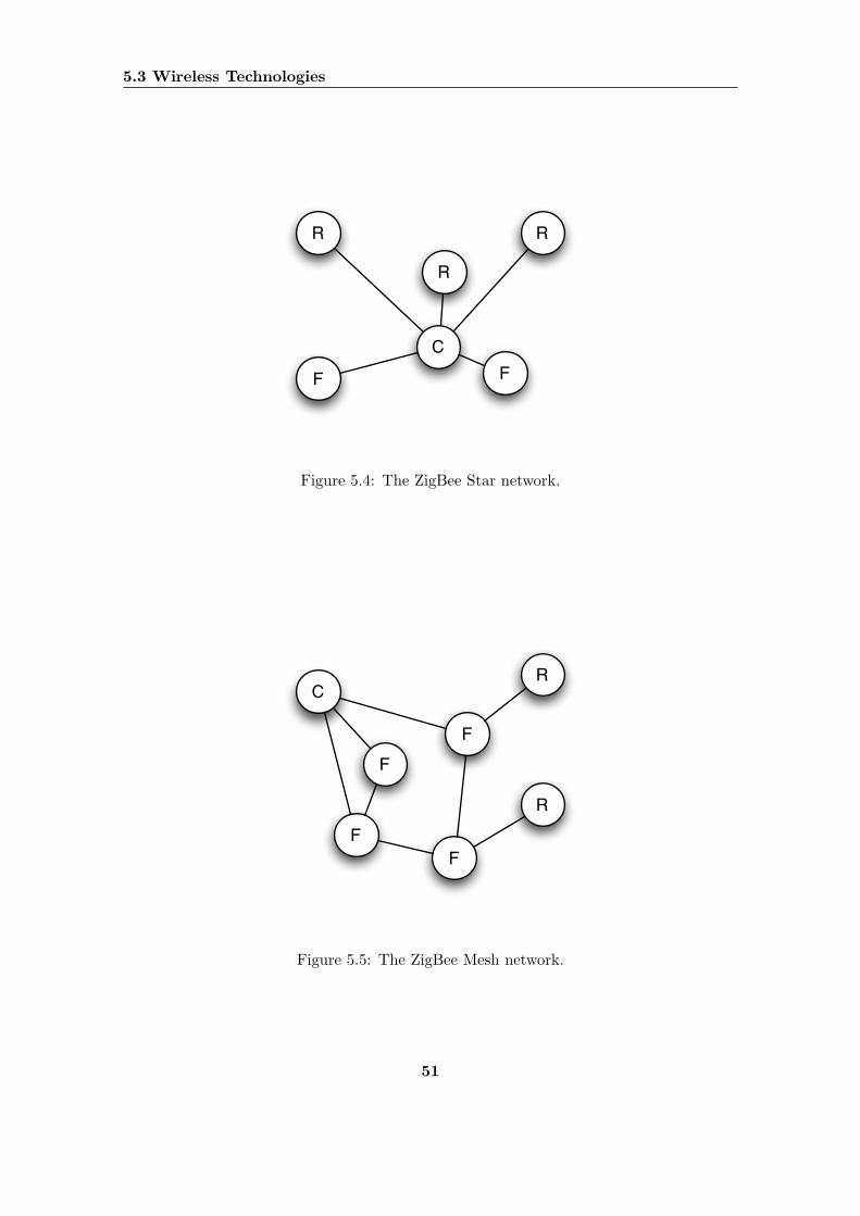
5.3 Wireless Technologies
C
F F
R
R
R
Figure 5.4: The ZigBee Star network.
C
F
F
F
F
R
R
Figure 5.5: The ZigBee Mesh network.
51
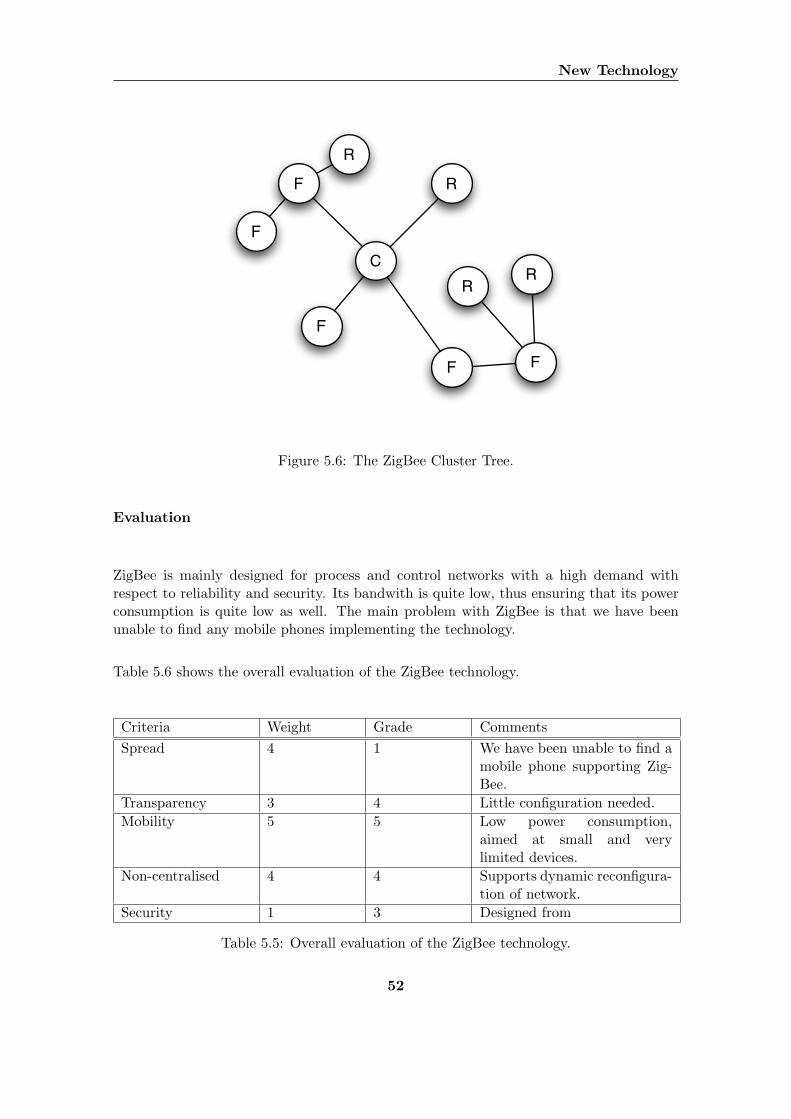
New Technology
C
R
F F
F
F
F
R
RR
Figure 5.6: The ZigBee Cluster Tree.
Evaluation
ZigBee is mainly designed for process and control networks with a high demand withrespect to reliability and security. Its bandwith is quite low, thus ensuring that its powerconsumption is quite low as well. The main problem with ZigBee is that we have beenunable to find any mobile phones implementing the technology.
Table 5.6 shows the overall evaluation of the ZigBee technology.
Criteria Weight Grade CommentsSpread 4 1 We have been unable to find a
mobile phone supporting Zig-Bee.
Transparency 3 4 Little configuration needed.Mobility 5 5 Low power consumption,
aimed at small and verylimited devices.
Non-centralised 4 4 Supports dynamic reconfigura-tion of network.
Security 1 3 Designed from
Table 5.5: Overall evaluation of the ZigBee technology.
52
5.3 Wireless Technologies
5.3.5 Wireless Local Area Network
Wireless Local Area Network (WLAN) is one of the most common wireless technologiestoday. The WLAN standard was introduced by the Institute of IEEE 3 after seven yearsof development in 1997. WLAN is traditionally defined as any wireless medium thatis able to connect users to a local area network. The 802.11 specification defined byIEEE includes three standards, 802.11a, 802.11b and 802.11g. All the standards useradio frequency technology to communicate, but each standard operates with differentbandwidths and frequencies. 802.11a is the standard with the highest bandwidth, allowingtransfers up to 54 Mbps. There are two possible types of infrastructures to choose fromwhen implementing a WLAN:
Infrastructure mode: This mode provides mobile WLAN devices with an access pointto a wired network.
Ad hoc mode: In this mode mobile WLAN devices communicate directly with eachother. Devices within range of each other can discover each other and communicatelike peers.
The ad hoc mode, that supports directly communication between devices, is the relevantoperation mode of a WLAN for this project. WLAN is mainly supported by mediumand large devices, because of its relatively large power consumption, but during the lastmonths the mobile phone industry has started to release mobile phones with WLANsupport. The Wi-Fi Alliance 4 is a nonprofit international association formed in 1999 tocertify interoperability of wireless Local Area Network products based on IEEE 802.11specification [7]. According to a search in their certified product listings, done november2004, only two mobile phones have passed the certification process: MPx from Motorolaand Nokia 9500 Communicator from Nokia.
Security
WLAN transmissions can be open or secure. If a transmission is open then everyone witha WLAN receiver can access the data. If the transmission is secure, then the receiver needsto share a Wired Equivalent Privacy (WEP) key with the sender. WEP is an encryptionsystem that WLAN uses to encode data that is being transmitted over air. WEP can beconfigured in 3 different modes [31]:
• No encryption
• 40 bit encryption
• 128 bit encryption
3http://www.ieee.org/4http://www.wi-fi.org
53
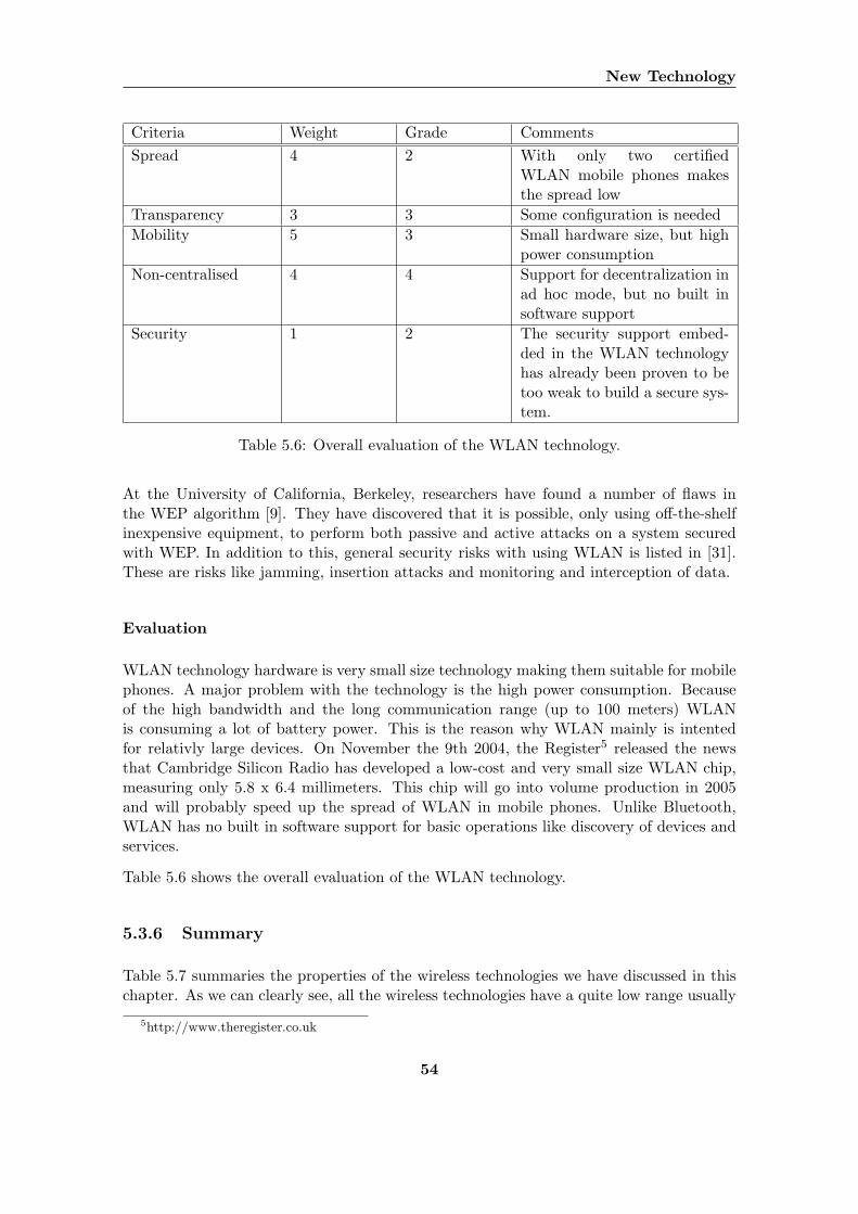
New Technology
Criteria Weight Grade CommentsSpread 4 2 With only two certified
WLAN mobile phones makesthe spread low
Transparency 3 3 Some configuration is neededMobility 5 3 Small hardware size, but high
power consumptionNon-centralised 4 4 Support for decentralization in
ad hoc mode, but no built insoftware support
Security 1 2 The security support embed-ded in the WLAN technologyhas already been proven to betoo weak to build a secure sys-tem.
Table 5.6: Overall evaluation of the WLAN technology.
At the University of California, Berkeley, researchers have found a number of flaws inthe WEP algorithm [9]. They have discovered that it is possible, only using off-the-shelfinexpensive equipment, to perform both passive and active attacks on a system securedwith WEP. In addition to this, general security risks with using WLAN is listed in [31].These are risks like jamming, insertion attacks and monitoring and interception of data.
Evaluation
WLAN technology hardware is very small size technology making them suitable for mobilephones. A major problem with the technology is the high power consumption. Becauseof the high bandwidth and the long communication range (up to 100 meters) WLANis consuming a lot of battery power. This is the reason why WLAN mainly is intentedfor relativly large devices. On November the 9th 2004, the Register5 released the newsthat Cambridge Silicon Radio has developed a low-cost and very small size WLAN chip,measuring only 5.8 x 6.4 millimeters. This chip will go into volume production in 2005and will probably speed up the spread of WLAN in mobile phones. Unlike Bluetooth,WLAN has no built in software support for basic operations like discovery of devices andservices.
Table 5.6 shows the overall evaluation of the WLAN technology.
5.3.6 Summary
Table 5.7 summaries the properties of the wireless technologies we have discussed in thischapter. As we can clearly see, all the wireless technologies have a quite low range usually
5http://www.theregister.co.uk
54
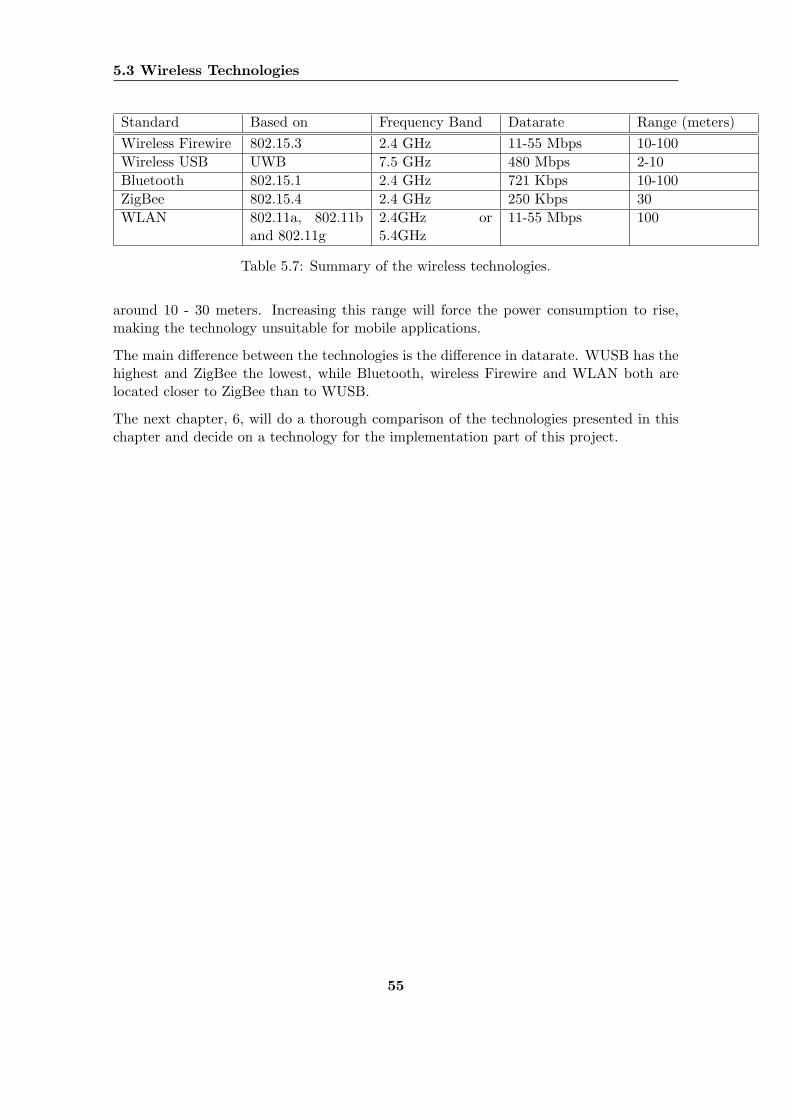
5.3 Wireless Technologies
Standard Based on Frequency Band Datarate Range (meters)Wireless Firewire 802.15.3 2.4 GHz 11-55 Mbps 10-100Wireless USB UWB 7.5 GHz 480 Mbps 2-10Bluetooth 802.15.1 2.4 GHz 721 Kbps 10-100ZigBee 802.15.4 2.4 GHz 250 Kbps 30WLAN 802.11a, 802.11b
and 802.11g2.4GHz or5.4GHz
11-55 Mbps 100
Table 5.7: Summary of the wireless technologies.
around 10 - 30 meters. Increasing this range will force the power consumption to rise,making the technology unsuitable for mobile applications.
The main difference between the technologies is the difference in datarate. WUSB has thehighest and ZigBee the lowest, while Bluetooth, wireless Firewire and WLAN both arelocated closer to ZigBee than to WUSB.
The next chapter, 6, will do a thorough comparison of the technologies presented in thischapter and decide on a technology for the implementation part of this project.
55
Chapter 6
Evaluation
6.1 Evaluation of Related Projects
In this section we will go through all related projects described above in Chapter 4.1 andChapter 4.2.
6.1.1 Prototypes
This section will evaluate and summarize the contribution of the related prototypes de-scribed in Chapter 4.1.
The iCloud Project
The iCloud project is very interesting in many different ways. First of all because it isbased upon the fact that a lot of people are carrying around mobile devices with wirelesstechnology. People move around and meet other people, forming a group that may share acommon goal or interest. The people working on the ICloud project describes how peoplein a ubiquitous computing world is willing to share information with each other. Anotherinteresting aspect of this project is that they have made an architecture that is based uponad hoc P2P communication.
The project gives us an overview of the challenges and design goals of collaborative appli-cations that utilizes automatically exchange of information. The simple architecture thatis proposed, focuses only on automatically information exchange between devices. Withour framework it should also be possible to develop application that are controlled by userinteraction.
IPAD/Hummingbird
The Hummingbird project is quite old, finished in 1999. Although the devices used weremade special for the purpose, it contributes with some important findings to the domain
56
6.1 Evaluation of Related Projects
of mobile collaboration. After doing different kind of experiments, the researchers con-cluded that face-to-face communication is an important aspect of collaboration. Increasedpresence awareness makes people easier initiate a face-to-face communication.
These findings contribute to our theory of collocated collaboration described in Chapter3.3.2. The prototype is a good example of an application that could be made by using ourframework.
6.1.2 Frameworks and Architectures
This section will evaluate and summarize the contribution of the related frameworks andarchitectures described in Chapter 4.2.
JXTA, JXME Proxied and JXME Proxyless
The JXTA project introduces a terminology for describing P2P systems. The project isrelevant for us because it defines the basic mechanisms and concepts that the more relevantprojects JXME Proxied and JXME Proxyless is based upon. It defines an infrastructurefor building stationary non-mobile P2P systems.
The JXME Proxied architecture is a kind of hybrid P2P model, where the JXTA relaysare the central entities. If a mobile P2P system is implemented above an ad hoc networkusing the JXME Proxied framework, all the mobile devices have to be in proximity ofthe server, the JXTA relay, and communicate through this server. This architecture isconflicting with the nature of spontaneous ad hoc collaboration. For example, instantmessages can not be sent from one peer to another, because a peer has to poll the JXTArelay for new messages. Because of this, the JXME Proxied framework does not fit therequirements for our framework, which should be based upon a pure not hybrid P2Pmodel.
The proxyless JXME framework seems very promising, providing a decentralized lightweightP2P framework for ad hoc networks and mobile devices. The main problem with theproject is the progress. The architecture is designed and released, but still has to be re-viewed and a more low-detail design process or implementation has not yet started. Themain reason for this slow progress is probably because of the fact that it is very hardto implement the advanced P2P functionality of JXTA on such constrained devices likemobile phones. This is why we will limit the scope of our framework to communicationwithin a singlehop PAN. We will then avoid the problems with advanced routing and re-source allocation between devices in a multihop network that seems far away from beingsolved in the research community. We still may consider and be inspired by the conceptsdescribed in the architecture when reviewing and designing our own framework.
Proem
The Proem Architecture has been based upon experiences and commonalities extractedfrom implementations of a series of mobile applications for face-to-face collaboration. It
57
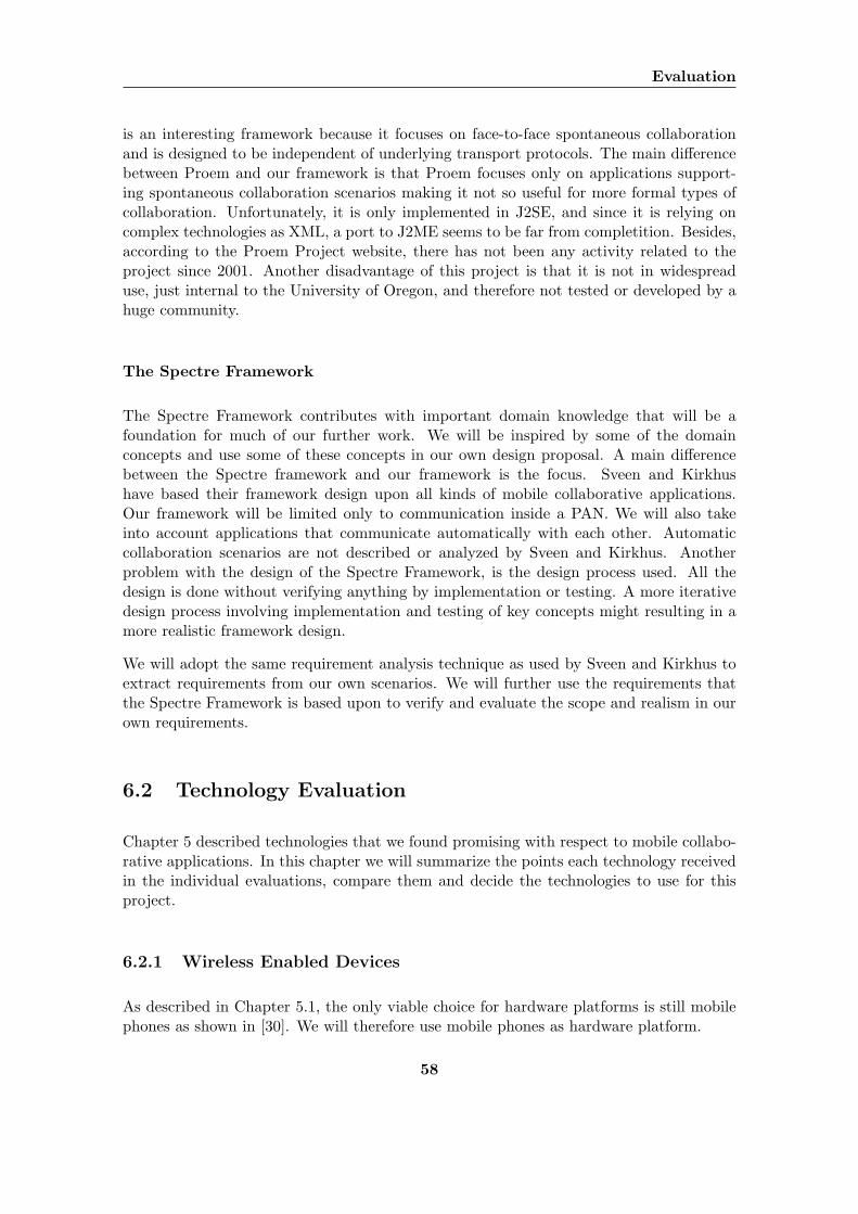
Evaluation
is an interesting framework because it focuses on face-to-face spontaneous collaborationand is designed to be independent of underlying transport protocols. The main differencebetween Proem and our framework is that Proem focuses only on applications support-ing spontaneous collaboration scenarios making it not so useful for more formal types ofcollaboration. Unfortunately, it is only implemented in J2SE, and since it is relying oncomplex technologies as XML, a port to J2ME seems to be far from completition. Besides,according to the Proem Project website, there has not been any activity related to theproject since 2001. Another disadvantage of this project is that it is not in widespreaduse, just internal to the University of Oregon, and therefore not tested or developed by ahuge community.
The Spectre Framework
The Spectre Framework contributes with important domain knowledge that will be afoundation for much of our further work. We will be inspired by some of the domainconcepts and use some of these concepts in our own design proposal. A main differencebetween the Spectre framework and our framework is the focus. Sveen and Kirkhushave based their framework design upon all kinds of mobile collaborative applications.Our framework will be limited only to communication inside a PAN. We will also takeinto account applications that communicate automatically with each other. Automaticcollaboration scenarios are not described or analyzed by Sveen and Kirkhus. Anotherproblem with the design of the Spectre Framework, is the design process used. All thedesign is done without verifying anything by implementation or testing. A more iterativedesign process involving implementation and testing of key concepts might resulting in amore realistic framework design.
We will adopt the same requirement analysis technique as used by Sveen and Kirkhus toextract requirements from our own scenarios. We will further use the requirements thatthe Spectre Framework is based upon to verify and evaluate the scope and realism in ourown requirements.
6.2 Technology Evaluation
Chapter 5 described technologies that we found promising with respect to mobile collabo-rative applications. In this chapter we will summarize the points each technology receivedin the individual evaluations, compare them and decide the technologies to use for thisproject.
6.2.1 Wireless Enabled Devices
As described in Chapter 5.1, the only viable choice for hardware platforms is still mobilephones as shown in [30]. We will therefore use mobile phones as hardware platform.
58
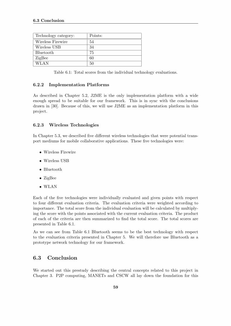
6.3 Conclusion
Technology category: Points:Wireless Firewire 54Wireless USB 34Bluetooth 75ZigBee 60WLAN 50
Table 6.1: Total scores from the individual technology evaluations.
6.2.2 Implementation Platforms
As described in Chapter 5.2, J2ME is the only implementation platform with a wideenough spread to be suitable for our framework. This is in sync with the conclusionsdrawn in [30]. Because of this, we will use J2ME as an implementation platform in thisproject.
6.2.3 Wireless Technologies
In Chapter 5.3, we described five different wireless technologies that were potential trans-port mediums for mobile collaborative applications. These five technologies were:
• Wireless Firewire
• Wireless USB
• Bluetooth
• ZigBee
• WLAN
Each of the five technologies were individually evaluated and given points with respectto four different evaluation criteria. The evaluation criteria were weighted according toimportance. The total score from the individual evaluation will be calculated by multiply-ing the score with the points associated with the current evaluation criteria. The productof each of the criteria are then summarized to find the total score. The total scores arepresented in Table 6.1.
As we can see from Table 6.1 Bluetooth seems to be the best technology with respectto the evaluation criteria presented in Chapter 5. We will therefore use Bluetooth as aprototype network technology for our framework.
6.3 Conclusion
We started out this prestudy describing the central concepts related to this project inChapter 3. P2P computing, MANETs and CSCW all lay down the foundation for this
59
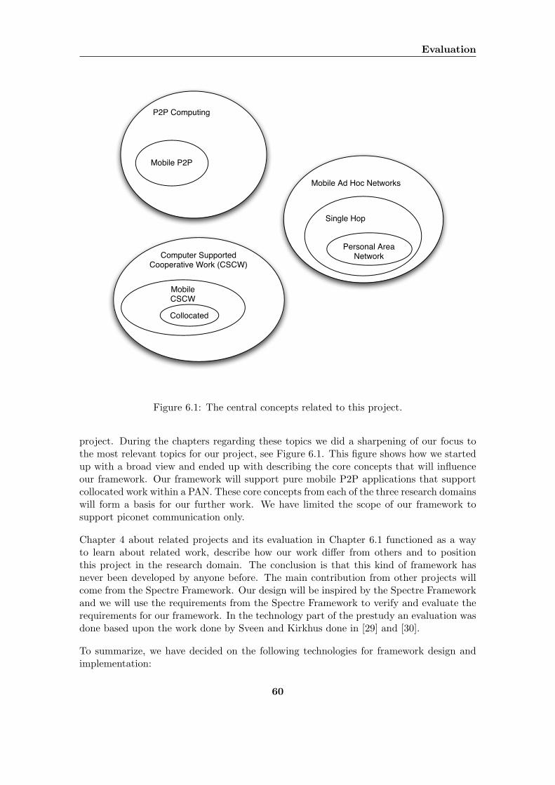
Evaluation
P2P Computing
Mobile P2P
Mobile Ad Hoc Networks
Single Hop
Personal AreaNetworkComputer Supported
Cooperative Work (CSCW)
Mobile CSCW
Collocated
Figure 6.1: The central concepts related to this project.
project. During the chapters regarding these topics we did a sharpening of our focus tothe most relevant topics for our project, see Figure 6.1. This figure shows how we startedup with a broad view and ended up with describing the core concepts that will influenceour framework. Our framework will support pure mobile P2P applications that supportcollocated work within a PAN. These core concepts from each of the three research domainswill form a basis for our further work. We have limited the scope of our framework tosupport piconet communication only.
Chapter 4 about related projects and its evaluation in Chapter 6.1 functioned as a wayto learn about related work, describe how our work differ from others and to positionthis project in the research domain. The conclusion is that this kind of framework hasnever been developed by anyone before. The main contribution from other projects willcome from the Spectre Framework. Our design will be inspired by the Spectre Frameworkand we will use the requirements from the Spectre Framework to verify and evaluate therequirements for our framework. In the technology part of the prestudy an evaluation wasdone based upon the work done by Sveen and Kirkhus done in [29] and [30].
To summarize, we have decided on the following technologies for framework design andimplementation:
60

6.3 Conclusion
Hardware: Mobile phones.
Platform: J2ME.
Transport: Bluetooth.
The framework will be designed and implemented in J2ME for mobile phones. Althoughthe framework is going to be independent of the underlying network technology, we needto use one particular network technology as a prototype technology. We have chosenBluetooth for this purpose.
61

Evaluation
62

Part II
Scenario and requirementsanalysis and evaluation
63

64
Chapter 7
Scenarios
In this chapter we will review the scenarios presented in [30] as well as present somenew scenarios. All the scenarios will be categorized according to the classification matrixintroduced in this chapter. In addition to being categorized, the scenario descriptions willfollow the same description pattern as in [30]. This means that all the scenarios will bedescribed through the following views where applicable:
• Goals and Preconditions
• Normal Action Sequence
• Critical Exceptions and Error Checking
7.1 Classification Matrix
We will here present a classification matrix for mobile collaborative scenarios. The ma-trix, shown in Table 7.1, has two dimensions. The first dimension, called Advanced P2PFunctionality, measures wether or not the scenario requires advanced P2P functionalitysuch as a routing algorithm or not. There are two rows in the first dimension:
1: The scenario is based on functionality that enables a search for required resources orservices conducted on a large network of nodes and subnets tied together in largescatternets. Users can, network-wise, be located with long distances between themand messages may require multiple hops to reach their targets.
2: The scenario is based on the exchange of information or the use of services on deviceslocated in a local, temporary ad hoc network. The users are located, network-wise,close to each other and messages are transmitted using a single hop inside a piconet.
The second dimension, called User Interaction, measures to what degree the user interactswith the application. The columns in this dimension are the same as the categories weused to describe different kinds of impromptu collaborative applications in Chapter 3.3.2.The tree columns in this dimension are:
65
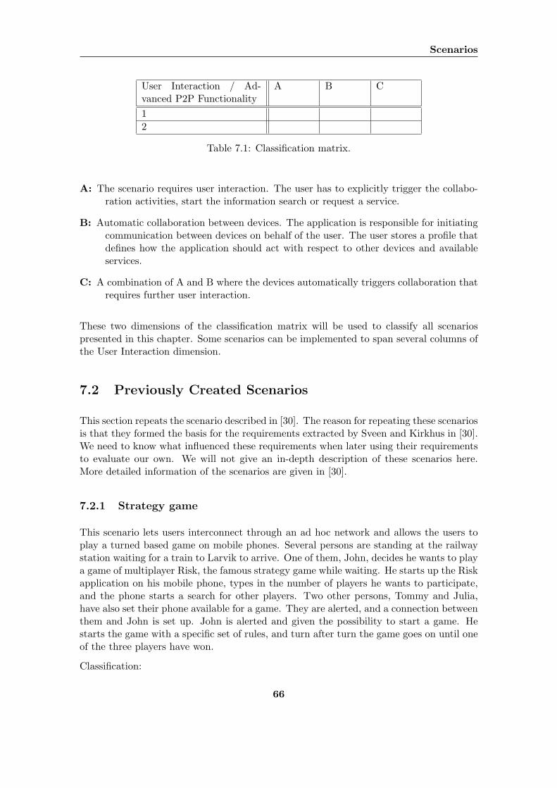
Scenarios
User Interaction / Ad-vanced P2P Functionality
A B C
12
Table 7.1: Classification matrix.
A: The scenario requires user interaction. The user has to explicitly trigger the collabo-ration activities, start the information search or request a service.
B: Automatic collaboration between devices. The application is responsible for initiatingcommunication between devices on behalf of the user. The user stores a profile thatdefines how the application should act with respect to other devices and availableservices.
C: A combination of A and B where the devices automatically triggers collaboration thatrequires further user interaction.
These two dimensions of the classification matrix will be used to classify all scenariospresented in this chapter. Some scenarios can be implemented to span several columns ofthe User Interaction dimension.
7.2 Previously Created Scenarios
This section repeats the scenario described in [30]. The reason for repeating these scenariosis that they formed the basis for the requirements extracted by Sveen and Kirkhus in [30].We need to know what influenced these requirements when later using their requirementsto evaluate our own. We will not give an in-depth description of these scenarios here.More detailed information of the scenarios are given in [30].
7.2.1 Strategy game
This scenario lets users interconnect through an ad hoc network and allows the users toplay a turned based game on mobile phones. Several persons are standing at the railwaystation waiting for a train to Larvik to arrive. One of them, John, decides he wants to playa game of multiplayer Risk, the famous strategy game while waiting. He starts up the Riskapplication on his mobile phone, types in the number of players he wants to participate,and the phone starts a search for other players. Two other persons, Tommy and Julia,have also set their phone available for a game. They are alerted, and a connection betweenthem and John is set up. John is alerted and given the possibility to start a game. Hestarts the game with a specific set of rules, and turn after turn the game goes on until oneof the three players have won.
Classification:
66
7.2 Previously Created Scenarios
Advanced P2P Functionality: 2.
User Interaction: A or C.
7.2.2 Information Exchange
This scenario explores information exchange between mobile phones in a large scale wirelessnetwork setting. The scenario supports connections and information exchange betweenpeople that are in long distance from each other. This requires interconnections betweenmany PAN devices and more advanced P2P functionality to support a multihop ad hocnetwork. Messages have to be routed from one phone to another, and advanced searchinghas to be supported.
Janet is working for a large consultant company and a major part of her job is to attendto conferences to keep updated within her field. She is now attending to a large conferencewith about 500 participants. All the participants are running a collaborative applicationon their mobile phones. This application enables all the participants to connect, share andsearch for any kind of information independent of their location in the large conferencehall.
Janet sets up a profile on her phone where she states her name, contact information,interests and what kind of resources she shares or is interested in. Janet uses this applica-tion during the conference to see what people is online, search for and downloading files,search for persons with the same interests and download pictures of people with matchinginterests.
Classification:
Advanced P2P Functionality: 1.
User Interaction: A.
7.2.3 Business Card Exchange
This scenario describes two people in proximity of each other that want to exchangebusiness cards. Mr.Johnson and Mr.Smith are at a conference and they start talkingabout a mutual interesting subject. After a short time Mr Smith has to leave, and theywant exchange business cards to be able to stay in touch and continue the discussion at alater occasion. Mr.Smith starts the application and starts a device discovery, followed bya service discovery. Mr.Johnsons’s mobile phone and business card application are foundduring the search and the transfer is started.
Classification:
Advanced P2P Functionality: 2.
User Interaction: A.
67
Scenarios
7.2.4 Tank Game
In this scenario, two users are using their mobile phones to play an action game. Thegame is a tank game where each player moves a tank around in a maze and tries to shootthe other players. The application must allow users to interconnect through an ad hocnetwork and the players must be able to play in real-time.
Nigel is attending a lecture at a large conference. The guest speaker is nervous, and aredigging into some technical details that Nigel does not find very interesting. He feels thathe can not just walk away, and decides to play a tank game. He starts the tank gameapplication, selects the map and starts the search for other players. He finds 4 activedevices in his proximity, but none of these have activated the tank game application.Because of no other players are found, Nigel sets the game on standby. After a fewminutes another person named Paul also start to feel a bit bored and loads the tank gameapplication. He finds the game that Nigel has started and connects to it. Nigel is alertedand the game is started.
Classification:
Advanced P2P Functionality: 2.
User Interaction: A.
7.2.5 Synchronization
This scenario handles the problem of synchronizing information between mobile phonesand personal computers (PC). When people move around they collect information withtheir mobile phones, but they often need to back it up or process it on a desktop computer.
Further on, Kirkhus and Sveen, here describes a salesperson named Johnny that is workingfor a high tech company. Through his work he meets a lot of people and needs to be ableto remember each encounter. He gathers different kind of information like business cards,information generated from a mobile social net application and other personal informationthat he manually registers.
In the scenario, we meet Johnny one day at his office. He has been out of office for a fewdays, meeting clients. He has gathered a lot of information on his phone and now wantto synchronize his PC with this information. He chooses to use Bluetooth for sendingthe data and starts up the synchronization software on both the mobile and the PC. Theapplications communicate and automatically figures out what information and entries thathave to be synchronised. The applications also finds out where there are conflicts and waitsfor Johnny to resolve the conflicts before continuing.
Classification:
Advanced P2P Functionality: 2.
User Interaction: A.
68
7.3 New Scenarios
7.3 New Scenarios
This section describes the new scenarios we have created. These scenarios are describedusing the same description pattern as in [30].
7.3.1 Converging Top Ten List
In today’s world with ever toughening competition in various markets, the consumersbenefit from knowing which service provider is the best. As an example here, we will usestudents trying to find out which bar has the lowest beer prices. This scenario can bemade generic to support any kind of top ten list.
Classification:
Advanced P2P Functionality: 2.
User Interaction: B.
Goals and Preconditions
The preconditions of this scenario include the mobile phones that the students carryaround with them as they move around on the campus area. The mobile phones have tobe able to make use of some kind of transfer medium such as Zigbee, WLAN or Bluetooth.
Each student will have a top ten list stored on their mobile phone. The goal is to have allthe various lists converged into one.
The goals for this scenario are the following:
• Students should be able to automatically connect their phones in an ad hoc network.
• Allow for the students to automatically exchange their top ten list via this ad hocnetwork in order for them to be compared and merged.
Normal Action Sequence
A student maintains a local list of the best beer prices known to him at the moment onhis phone. Whenever the student visits a bar with beer prices that changes this list, heregisters the price as well as the date this price was valid. Obviously, one student is unableto visit every available bar. This is where collaboration with others come in.
When the students moves around on the campus area, they enable their phones to beavailable for information exchange with other students running the same application.
As two students running the application pass in the hall or sit next to each other during alecture, their mobile phones will sense that they are in proximity and providing the sameservice. Without the need of any interaction from the students, the devices will connect
69
Scenarios
and exchange their top ten lists. On each of the phones, these two list will be comparedto produce a new list with the ten best prices from the two original lists. As time goesby and more and more students exchange lists by chance encounters, everyone’s lists willconverge into the same top ten list giving everyone up to date information on where tofind the best beer prices.
Critical Exceptions and Error Checking
If an encounter between to students ends to soon, chances are that the discovery andtransfer time will not have time to finish. In the case where the encounter is ended beforethe discovery time finishes, no measures will have to be taken. In the case where thetransmission of the top ten list is aborted due to errors, interference or other problems,two different strategies can be used:
• The entire list can be discarded as if the encounter never had taken place.
• If, for instance, the first three list entries have been transferred before communicationfails, these three entries can be merged with the local list, which leads to the topthree entries moving closer to the converged list.
7.3.2 Tourist Information
People in a city collect, provide and exchange digital information about their city thattourists may be interested in. When new tourists come to town, they can obtain usefulinformation about sights, restaurants, useful telephone numbers, etc. All this happensautomatically. The tourists just have to store information about what kind of informationthey are interested in.
Classification:
Advanced P2P Functionality: 2.
User Interaction: B.
Goals and Preconditions
First of all, to get this scenario to work properly, people living in a city have to be willingto produce and share information. Some people will do this voluntarily because they careabout the city they live in and want tourists to feel comfortable when staying there. Othersmight only be willing to produce and share these kind of information when getting paidfrom the local tourist office.
The application should provide a way to categorize information. When arriving a newcity, a tourist can specify in detail what kind of information they need during this stay.Information categories should be defined in some kind of hierarchical structure.
The goals for this scenario are the following:
70
7.3 New Scenarios
• The users should be able to contribute information and to specify what kind ofinformation they are interested in.
• The phones should automatically search for other phones with relevant information.
• The phones should exchange relevant information if found.
Normal action sequence
Henry and his wife, Fiona, has just arrived New York early saturday morning. They areon their honeymoon and are planning to spend the weekend in the city before heading onsouth to Florida. Its early in the morning and the couple has decided to spend the dayshopping down town. The couple are not sure what they want to do in the evening. Aftera short discussing they decide, since they are both interested in drama, that they want tovisit a theatre. But since its their first time in New York, they do not know where thetheatres are and what kind of plays that are available this weekend. They do not wantto spend time visiting a tourist office or browsing the web for the relevant information.They decide to use the tourist information application on their mobile phones to gatherthe information. They both register their requests for theatre information and set theapplications in search mode.
When the couple walk around in the streets, their mobile phones connect automaticallywith other mobile phones running the tourist information application and checks for the-atre information. For example Henry visits a coffee shop to buy a doughnut. There are afew people ahead of him in the queue and one of them is a man that also has the touristinformation application installed and turned on. Henrys phone finds the other phone andconnects to it. The application checks for relevant information, which is found, and thentransfers it from the other mans phone to Henrys phone.
The streets of New York are crowded and there are lot of people that have collected andare sharing information about theatres. Back on the hotel, after a long day of shopping,Henry and Fiona check their tourist information application. They find a lot of informationabout theatres, addresses, plays and recommendations and decide to buy tickets to LeonardBernsteins musical Wonderful Town at the Al Hirschfeld Theatre.
Critical Exceptions and Error Checking
A critical exception here could be that a transfer of information is interrupted. This couldhappen because one of the devices get out of power or the two deceives come out of rangefrom each other.
7.3.3 Ubiqutous Flea-market
If you want to get rid of some old furniture or other items that you no longer can findany use for, there are many different medias that can be used to reach potential buyers.A problem is that it is hard to reach the most interested buyer for your item.
Classification:
71
Scenarios
Advanced P2P Functionality: 2.
User Interaction: B or C.
Goals and Preconditions
For this scenario to work properly it has to have a large enough user base and of courseusers who have registered items they want to sell as well as user registered as interestedin buying certain items.
The goal of the scenario is to have a seller and a potential buyer automatically exchangecontact information, and thus helping them to get in touch and close a deal.
The goals for this scenario are the following:
• Allow for the users’ phones to automatically connect in an ad hoc network.
• A buyer phone should be able to check what items a phone running in seller modehas to offer.
• The phones should exchange contact information if a match is made.
Normal Action Sequence
John has just moved in with his fiance Mary. Previously they have had separate apart-ments, but moving into one makes a lot of their furniture redundant. In order to advertisethat he has items to sell, John register an ad for each item on his mobile phone andactivates its “Search for buyers” service.
The next day when John goes to the supermarket to shop for groceries he encounters alot of people, some of them have enabled their mobile phones in buyer mode. When Johnmoves close enough to a phone running in buyer mode, the phones connect and checkwether John is selling anything this particular buyer is interested in or not. If a match ismade, John’s contact info is copied to the buyer phone along with the add for the actualitem.
When the potential buyer comes home from the supermarket he checks his phone to see ifit has discovered any items he might be interested in. He sees John’s ad and decides thatthis item is something he might be interested in so he calls John to find out more aboutit.
An alternative path of action in this scenario is to have the mobile phone alert the sellerat once when a potential buyer is found. By doing this, the seller can start spontaneousconversation with the seller and close the deal right then and there. The option to beautomatically notified of a potential buyer should be left to the user to decide on a peritem basis.
72
7.3 New Scenarios
Critical Exceptions and Error Checking
A problem arises if the information is only partially transferred. For instance, the buyerchecks his phone and sees that an ad for an item he is interested in has been downloadedto his phone, but the contact information for the seller is missing or incomplete leavingthe buyer incapable of contacting the seller.
One solution here is to either trigger a notification message to the phones owner if com-munication fails after an interesting item is found. The other, and easy-way-out, wouldbe to discard the data in its entirety.
The choice between these to solutions should be included as options for the users.
7.3.4 Planning the Next Meeting
At the end of a meeting with several participants, the next meeting is often planned. Asthe number of participants increases the effort required to find a suitable time increases.A mobile collaborative application can be used to automate this process.
Classification:
Advanced P2P Functionality: 2.
User Interaction: A.
Goals and Preconditions
For this scenario to be applicable a group of people have to be attending the same meetingand they want to plan their next meeting. All the participants need to have mobile phonesthat are enabled to use this application. The mobile phones also need to have some kindof calender software that stores the calender information in a exchangeable format.
The goals for this scenario are the following:
• Allow for the meeting participants to connect their phones in an ad hoc network.
• The task of planning the next meeting should be automated by exchanging calendaritems, computing a common meeting time and placing it on all the participantsphones.
Normal Action Sequence
Bob, a project manager in a large consultant company, is starting to round up a meetingwith his project team and two representatives from the customer. They are currentlyworking on the requirements specification for the system that Bob’s company is going tobuild. However, the customer was not satisfied with the proposal that Bob and his team
73
Scenarios
presented. Now Bob need to plan a new meeting in two weeks time to go over a revisedrequirements specification proposal.
Bob asks everyone to enable their mobile phones to exchange calendar items. He thenenters into his phone an approximate date for the next meeting and sets his phone to finda time suitable for all the people in the room.
Bob’s phone then searches the room to find mobile phones that are ready to exchangecalendar items. As the phones are discovered the other participants free time at theapproximate date is exchanged. When Bob’s phone has gathered the free time fromeveryone, it calculates a meeting time that is suitable for everyone and transmits this backto the others.
The next meeting can then be automatically added to all the other participants calendars.
Critical Exceptions and Error Checking
The main errors that can occur here, is that a connection is lost. Since the setting ismore formal where everyone is located quite still in the same room, reconnection andretransmission can be attempted until the transfer is complete.
Another problem can arise if the phone doing the planning is unable to find a suitablemeeting time. If this is the case, the application should expanding its search area in bothdirections and try again.
7.3.5 PAN Instant Messaging
Instant messaging has grown to be maybe the most popular and most used application ofP2P technology. People use instant messaging applications to communicate directly withfriends and colleagues using PCs connected to the Internet. Lately Ericsson, Motorola,and Nokia have established the Wireless Village project1. This projects aims to developan architecture for Mobile Instant Messaging and Presence (IMPS) that can make instantmessaging available on mobile phones over some kind of cellular network like GSM, EDGEor UMTS. The following scenario will describe an ad hoc instant messaging service insidea PAN. This will provide collocated people to communicate instantly with their mobilephones for free without using a cellular network.
Classification:
Advanced P2P Functionality: 2.
User Interaction: A.
1http://www.openmobilealliance.org/tech/affiliates/wv/wvindex.html
74
7.3 New Scenarios
Goals and Preconditions
Preconditions for this scenario is to have a group of people, two or more, that are collocatedin same place, that want to communicate. The goal of the scenario is to enable these peopleto communicate directly and instantly with each other by using their mobile phones.Messages are typed in using the same technique as used when writing SMSs and are sentto all the participants of a conversation.
The goals for this scenario are the following:
• The users should be able to interconnect through an ad hoc network by using theirmobile phones and an ad hoc PAN technology (like Bluetooth).
• The users should be able to communicate directly and instantly with each otherthrough the network.
• The users should be able to type messages, or select files and send them to otherusers.
• The users should be able to choose if they want to send information to one or moreusers, or broadcast to all the other users in the network.
Normal Action Sequence
Peter and Daniel are friends and are both students at a university. They are studyingComputer Science and are now attending to a lecture in Compiler Techniques. There areabout 150 students almost filling up the auditorium. Peter and Daniel did not arrive at theauditorium at the same time, so now they are sitting two rows away from each other and arenot able to communicate by voice. After the professor has introduced the theme of today’slecture, lexical analysis, Peter and Daniel both become quite frustrated. They know allabout lexical analysis because they had a project on this in another course. Althoughthey feel, that they can not leave the lecture because the professor is going to talk aboutthe exam the last quarter. Peter decides to invite Daniel to an ad hoc conversation. Hestarts his PAN instant messaging application on his mobile phone and starts a search fordevices. The application finds Daniels device and Peter chooses to establish a connectionto this device by creating a closed chat group. Daniel is now alerted, the mobile phone inhis pocket vibrates and he accepts the request for a conversation from Peter. Now Peterand Daniel can communicate, and they go on discussing a project in another course for thenext half hour. They also send each other project related files. During the conversation, athird person named Bill, also starts the PAN instant messaging application. Bill searchesfor available devices, finds Peter and Daniel, and tries to connect to their conversation.Peter, who initiated the conversation is alerted and is asked if he allows Bill to join theconversation. Peter feels that the conversation between him and Daniel is kind of private,so he simply rejects the request from Bill. Bill receives a message, which says that hisrequest is rejected. After a while, when the professor start talking about the exam, Peterand Daniel close the application and starts listening to the professor again.
75
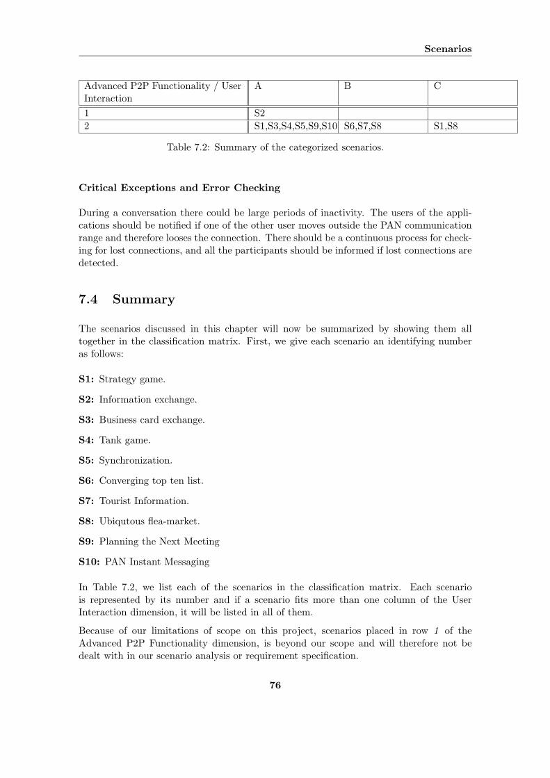
Scenarios
Advanced P2P Functionality / UserInteraction
A B C
1 S22 S1,S3,S4,S5,S9,S10 S6,S7,S8 S1,S8
Table 7.2: Summary of the categorized scenarios.
Critical Exceptions and Error Checking
During a conversation there could be large periods of inactivity. The users of the appli-cations should be notified if one of the other user moves outside the PAN communicationrange and therefore looses the connection. There should be a continuous process for check-ing for lost connections, and all the participants should be informed if lost connections aredetected.
7.4 Summary
The scenarios discussed in this chapter will now be summarized by showing them alltogether in the classification matrix. First, we give each scenario an identifying numberas follows:
S1: Strategy game.
S2: Information exchange.
S3: Business card exchange.
S4: Tank game.
S5: Synchronization.
S6: Converging top ten list.
S7: Tourist Information.
S8: Ubiqutous flea-market.
S9: Planning the Next Meeting
S10: PAN Instant Messaging
In Table 7.2, we list each of the scenarios in the classification matrix. Each scenariois represented by its number and if a scenario fits more than one column of the UserInteraction dimension, it will be listed in all of them.
Because of our limitations of scope on this project, scenarios placed in row 1 of theAdvanced P2P Functionality dimension, is beyond our scope and will therefore not bedealt with in our scenario analysis or requirement specification.
76
Chapter 8
Scenario Analysis
The scenarios described in Chapter 7 demonstrates what applications that can be builtusing our framework. In addition to give samples of usage, the scenarios also describethe complete usage patterns that we will focus on. These usage patterns form a basisfor defining the requirements the framework must meet in order to support the describedscenarios.
In [50], Sutcliffe present a method for deducing the functional and non-functional require-ments from scenario scripts. Scenario scripts are written in a non formal manner like ourscenarios. Sveen and Kirkhus also use this method for analysing their requirements in[30].
The analysis is based on the steps shown in Figure 8.1. These steps are:
Goal analysis: The goal analysis starts by looking at the scenario goals. For each goal,the following questions are asked:
1. Does the user’s goal require computerized support?
2. Does the goal describe a quality or performance property?
3. If the goal does not require computerized support, can it be achieved by amanual effort?
4. Does the goal require a management decision about resources and responsibil-ities?
5. Can the scenario goal and its associated task be fully automated?
Inbound event analysis: This step aims to identify the events that take place duringa scenario and elaborate these to find their corresponding functional requirements.When all events that have implications for the framework have been uncovered,we will compare these to the requirements found during the goal analysis. If therequirements do not support the event, requirement will be added to cover the event.
Categorize system output: This step aims to identify what output events that aredescribed by the scenarios. Output events are events that can be placed in one ofthe following categories:
77
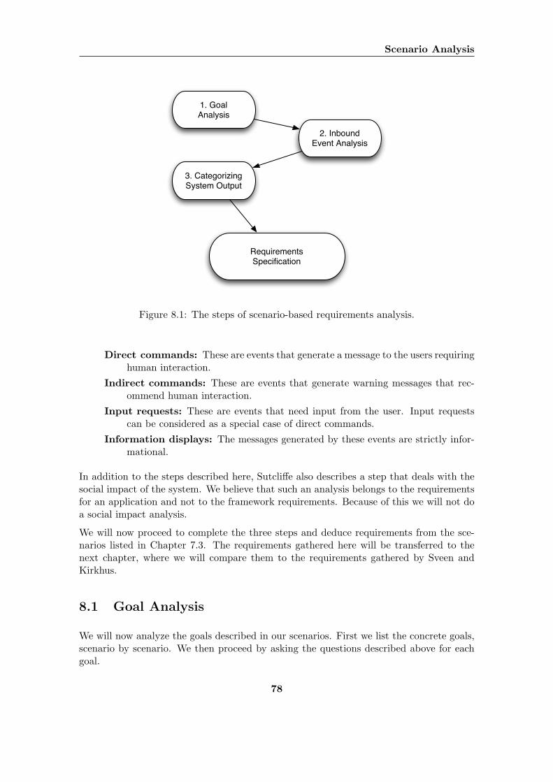
Scenario Analysis
1. Goal Analysis
2. Inbound Event Analysis
3. Categorizing System Output
Requirements Specification
Figure 8.1: The steps of scenario-based requirements analysis.
Direct commands: These are events that generate a message to the users requiringhuman interaction.
Indirect commands: These are events that generate warning messages that rec-ommend human interaction.
Input requests: These are events that need input from the user. Input requestscan be considered as a special case of direct commands.
Information displays: The messages generated by these events are strictly infor-mational.
In addition to the steps described here, Sutcliffe also describes a step that deals with thesocial impact of the system. We believe that such an analysis belongs to the requirementsfor an application and not to the framework requirements. Because of this we will not doa social impact analysis.
We will now proceed to complete the three steps and deduce requirements from the sce-narios listed in Chapter 7.3. The requirements gathered here will be transferred to thenext chapter, where we will compare them to the requirements gathered by Sveen andKirkhus.
8.1 Goal Analysis
We will now analyze the goals described in our scenarios. First we list the concrete goals,scenario by scenario. We then proceed by asking the questions described above for eachgoal.
78
8.1 Goal Analysis
8.1.1 Concrete Scenario Goals
The following goals are presented in our scenarios:
Converging Top Ten List
The following goals are presented in the scenario:
1-1: Students should be able to automatically connect their phones in an ad hoc network.
1-2: Allow for the students to automatically exchange their top ten list via this ad hocnetwork in order for them to be compared and merged.
Tourist Information
The goals for this scenario are the following:
2-1: The users should be able to contribute information and to specify what kind ofinformation they are interested in.
2-2: The phones should automatically search for other phones with relevant information.
2-3: The phones should exchange relevant information if found.
Ubiqutous Flea Market
The following goals are presented in the scenario:
3-1: Allow for the users’ phones to automatically connect in an ad hoc network.
3-2: A buyer’s phone should be able to check what items a phone running in seller modehas to offer.
3-3: The phones should exchange contact information if a match is made.
Planning the Next Meeting
The following goals are identified:
4-1: Allow for the meeting participants to connect their phones in an ad hoc network.
4-2: The task of planning the next meeting should be automated by exchanging calendaritems, computing a common meeting time, and placing it on all the participantsphones.
79
Scenario Analysis
PAN Instant Messaging
The following goals are identified:
5-1: The users should be able to interconnect through an ad hoc network by using theirmobile phones and an ad hoc PAN technology (like Bluetooth).
5-2: The users should be able to communicate directly and instantly with each otherthrough the network.
5-3: The users should be able to type in messages or exchange files and send them toother users.
5-4: The users should be able to choose if they want to send information to one or moreusers, or broadcast it to all the other users in the network.
8.1.2 Requirements Elaboration
We now proceed in uncovering requirements by asking the question specified previouslyin this chapter.
Question 1
When we take a closer look at the goals identified above, the following requirements canbe deduced by checking wether the goals need computerized support or not:
FR1: The system must support mobile phones.
FR2: The system must support creation of ad hoc networks.
FR3: The system must be able to connect to an existing ad hoc network.
FR4: Nodes in a network must be able to exchange messages.
FR5: The system must be able to create a group of nodes related to a specific application.
FR6: The system must support multicasting and broadcasting of messages within a group
FR1 surfaces due to the fact that all scenarios deal with collaboration on mobile phonesas well as ad hoc networks, also giving us FR2 and FR3. The nodes in the network needto be able to exchange messages, if not interconnecting the phones looses its purpose.
80
8.2 Inbound Event Analysis
Question 2
We can deduce the following requirements by checking which goals that have some sort ofquality requirements that need to be fulfilled :
NFR1: The system must be able to transfer messages fast enough for real time interac-tion.
The scenario “PAN instant messaging” involves users communicating in real time on aPAN. Due to this, the system must be fast enough for this real time interaction to takeplace.
NFR2: The system must be able to detect the disconnection of nodes within a group andnotify relevant applications about this.
The other participants should be notified if a user running the “PAN instant messag-ing” application moves outside the communication range of the other participants in theconversation.
Question 3
This question is not applicable to any of our identified goals.
Question 4
Due to our limitations of scope, e.g. only considering one piconet, this question does notapply to our scenarios.
8.2 Inbound Event Analysis
We will now analyze the inbound events described in our scenarios.
8.2.1 Event Identification
This section will list the identified inbound events found in each of the scenarios.
Converging Top Ten List
In 1-1: The students enter a new beer price into their application.
In 1-2: The students set their phones to automatically and continuously search for otherphones with the same application running.
81
Scenario Analysis
In 1-3: Two students phones connect at a chance encounter.
In 1-4: Top ten lists are exchanged between the phones.
In 1-5: The top ten lists are compared on each phone.
Tourist Information
In 2-1: Henry and Fiona register what kind of information they want to receive.
In 2-2: Henry and Fiona set their phones to automatically and continuously search forother phones with the same application running.
In 2-3: Henry’s phone connects to the other mans phone.
In 2-4: The two phones communicate to find out if they have relevant information toprovide each other.
In 2-5: The relevant information is transferred.
Ubiqutous Flea Market
In 3-1: John registers his old furniture as ads on his mobile phone.
In 3-2: Buyers have to register what kind of items they are interested in on their phones.
In 3-3: John’s phone and potential buyers’ phones connect as they pass each other duringthe day.
In 3-4: If the buyer phone decides that its owner is interested in the items John is selling,the ads are transferred to the buyer phone along with John’s contact information.
Planning the Next Meeting
In 4-1: Bob sets up an ad hoc network and asks everyone to connect to it.
In 4-2: Bob’s phone gathers the calendars of all the participants around the proposedtime.
In 4-3: Bob’s phone sends the calendar item containing the meeting to all the partici-pants.
PAN Instant Messaging
In 5-1: Peter starts the PAN instant messaging application.
In 5-2: Peter starts a search for devices.
82
8.2 Inbound Event Analysis
In 5-3: Peter selects Daniel’s device and invite him to a conversation by creating a closedchat group
In 5-4: Daniel is alerted and he accepts the request for a conversation.
In 5-5: Peter and Daniel send messages and files to each other.
In 5-6: Bill starts a search for devices.
In 5-7: Bill tries to connect to the conversation of Peter and Daniel.
In 5-8: Peter rejects the request from Bill.
8.2.2 Requirements Elaboration
We now proceed in uncovering requirements by analyzing the inbound events identifiedin the previous section. For each event we will examine if it is the responsibility of theframework or the application layer. We will also check if the event is supported by anearlier identified requirement.
In 1-1: This is the application’s responsibility.
In 1-2: The system must be able to search for other phones supporting the same service.
In 1-3: Supported by FR2 and FR3.
In 1-4: Supported by FR4.
In 1-5: This is the application’s responsibility.
In 2-1: This is the application’s responsibility.
In 2-2: Same as for In 1-2, in addition the application is responsible for the continuouslysearch by starting a new search after a search has completed.
In 2-3: Supported by FR2 and FR3.
In 2-4: Exchange of information is supported by FR4. It is the application’s responsibilityto include logic to decide if the information is relevant.
In 2-5: Supported by FR4.
In 5-1: This is the application’s responsibility.
In 5-2: Same as for In 1-2.
In 5-3: Supported by FR2. In addition, the system must support the creation of a groupas closed or open.
In 5-4: Supported by FR3 and FR4.
In 5-5: Supported by FR4.
83
Scenario Analysis
In 5-6: Same as for In 1-2.
In 5-7: The system must support to allow a node to try to join an existing closed group.
In 5-8: The system must allow users in a closed group to reject other nodes to join thegroup.
Summarized, the new requirements in this section are the following:
FR7: The system must be able to search for other phones supporting the same service.
FR8: The system must support the creation of groups as closed or open.
FR9: The system must support to allow a node to try to join a closed group.
FR10: The system must allow users in a closed group to reject other nodes to join thegroup.
In an open group any node can join, which make them suitable for automatic exchange ofinformation. Closed groups call for a network administrator(initially the user that createdthe group) to accept incoming join requests from new nodes. Because a user should be ableto join and leave an open group without permission, we add an additional requirement:
FR11: The system must support to allow a node to join an open group.
8.3 Categorize System Output
In this section we will identify what output events that are described by the scenarios.These events will be categorized as direct commands, indirect commands, input requestsor information displays.
8.3.1 Event Identification
This section will list the identified output events in each of the scenarios.
Converging Top Ten List
There is no information automatically displayed displayed to the user in this scenario.
Tourist Information
As with the “Converging Top Ten List” scenario, there is no information automaticallydisplayed to the user in this scenario either.
84
8.3 Categorize System Output
Ubiqutous Flea Market
As described in this scenario, the application can be run in one of two modes. One mode iswhere the ads are automatically downloaded to the buyers phone and he checks his phonefor new ads when he gets home. This does not require any specific functionality from theframework.
However, if the alternative action sequence is followed, the buyer phone will automaticallynotify the buyer at the minute an interesting ad is downloaded. This will lead to arequirement where the applications needs to present information to the user. We believethat in this case this system output is application specific and no framework requirementscan be elaborated from it.
Planning the Next Meeting
As with the “Converging Top Ten List” scenario, there is no information automaticallydisplayed to the user in this scenario either.
PAN Instant Messaging
Out 5-1: Daniel receives an alert about the invitation from Peter. Type: Input request
Out 5-2: Peter is alerted about the request from Bill. Type: Input request
Out 5-3: Bill receives a message which says that his request is rejected. Type: Informa-tion display
8.3.2 Requirements Elaboration
Out 5-1 and 5-2: The system must be able to present decision messages to the user.
The question presented to the user can be of any form where the user can reply witheither “Accept” or “Reject”.
Out 5-2 and 5-3: The system must be able to present information to the user aboutframework related events.
Summarized this gives us the following new requirements:
FR12: The system must be able to present decision messages to the user.
The question presented to the user can be of any form where the user can reply witheither “Accept” or “Reject”.
FR13: The system must be able to present information to the user about frameworkrelated events.
85
Chapter 9
Requirements
This chapter deals with the requirements the framework will have to meet. We start bylisting the requirements gathered in [30]. We then move on to compare these requirementsto the requirements gathered from our scenarios in Chapter 8. We will first explain whichrequirements from Sveen and Kirkhus that we have removed. Then we will explain howour requirements from our own requirement analysis are related or not related to therequirements from Sveen and Kirkhus. Then we will describe the remaining requirementsfrom Sveen and Kirkhus that we will add to our own set of requirements. Finally wewill present the complete list with revised prioritized requirements that we will base ourframework design on.
9.1 Previously Gathered Requirements
In [30], Sveen and Kirkhus analyzed the scenarios described in the Chapter 7.2 and deducedthe requirements presented in this section. All requirements listed that come from Sveenand Kirkhus has an identifier starting with the letters SK.
9.1.1 Functional Requirements
SK-FR1: The system must support mobile phones.
SK-FR2: The system must support creating a network without relying on a centralizedinfrastructure, e.g. the system must be able to set up a network without using acentralized device acting as a server.
SK-FR3: The system must be able to form a connected group consisting of two or moredevices sharing the same application. This means that it must be possible to createa virtual grouping, both to know which devices to communicate with and to enableexclusion of some devices.
SK-FR4: The system must be able to transfer data to one or more specific devices. Thismeans that the system must support addressable data and that it may define one ormore recipients.
86
9.1 Previously Gathered Requirements
SK-FR5: The system must support resource management to balance the network load.Resource management must be done in the system to ensure optimal performance.This requires that if one network node is suffering under heavy load, the systemmust be able to see this and reroute traffic to compensate for this.
SK-FR6: The system must allow applications to create a new group or join existinggroups. If a group of the required type is found the application must be able to jointhis grouping. If no suitable grouping is found the application must create a newone.
SK-FR7: The system must be able to limit the number of members in a group. Thisrequirement is motivated by the fact that you do not want the running applicationto handle incoming connections that are not needed. If the application only wantsthree connections, it should not have to handle any extra connections that otherdevices attempt to create.
SK-FR8: The system must support searching for existing groups. The system mustfacilitate the ability to to search for groups sharing a specified applications.
SK-FR9: The system must support continuous search for groups.
SK-FR10: The system must support sending the same data to two or more devices. Itmust be possible to send data to a number of devices. This can either be a messagethat is sent to everyone connected to the network formed by the system or to aspecific subgroup of the network.
SK-FR11: The system must be able to support different kinds of network mediums.
SK-FR12: The applications must be independent of what network medium that is cur-rently in use within the system. The application that is using the system to handlenetwork traffic should not have to know what kind of network medium that is used bythe device or make any kinds of adjustment to fit a specific network implementation.
SK-FR13: The system must be able to query the running application if the incoming oroutgoing connection or transfer is allowed.
SK-FR14: The system must be able to notify all users connected to a network when anew device connects.
SK-FR15: The system must be able to identify where a transfer originated from. Tobe able to send direct replies to a given device, it must be possible to see where atransfer originated from.
9.1.2 Non Functinal Requirements
SK-NFR1: The system must be able to guarantee correct data transfer. A transactionmust either be performed correctly or not at all.
SK-NFR2: The system must be fast enough to allow for near real time data transactions.
87

Requirements
SK-NFR3: The system must not let the devices have access to messages not intended forthemselves. This requirement is intended for situations where the device in questionis a relay for some other devices. Data that is relayed to other devices must not beavailable to applications running on the relay device.
SK-NFR4: The system must be able to detect and notify applications running on thedevice when a transfer fails.
9.2 Requirements Evaluation
In [30], Sveen and Kirkhus initially set out to design and implement a full scale P2Pframework for mobile collaboration. This included the interconnection of several Bluetoothpiconets requiring advanced routing protocols for sending messages using multiple hops toreach their destinations. This project has a more narrow scope than Sveen and Kirkhusto make sure that the framework can be realized.
In addition, we have added some new scenarios to the scenario set proposed in [30]. Therequirements need to be verified against the new scenarios to make sure that they are not inconflict. We will also check whether the new scenarios have introduced new requirementsfor the system.
9.2.1 Removal of Requirements
Due to the limitations of scope in this project, some of the requirements gathered by Sveenand Kirkhus in [30] are irrelevant for this project. We will now discuss the irrelevantrequirements and why they are not necessary for us.
SK-FR5: The system must support resource management to balance the network load. . .
SK-NFR3: The system must not let the devices have access to messages not intendedfor themselves. . .
These two requirements are not relevant for our framework because we are not planningto include advanced multihop P2P functionality. All communication will appear directlybetween nodes in a PAN and no performance balancing is needed. There will not benodes in our framework that will function as relays. Therefore privacy issues as describedin SK-NFR3 are not that important.
SK-NFR1: The system must be able to guarantee correct data transfer. A transactionmust either be performed correctly or not at all.
The responsibility of error correction and error detection will be moved from the frameworkto the network layer. The network should guarantee correct data transfer. If a networktechnology not including error correction or error detection is deployed then separate errorcorrection and detection modules have to be built between the framework and the network.
88
9.2 Requirements Evaluation
SK-FR9: The system must support continuous search for groups.
This will not be the responsibility of our framework. An application that want to facilitatecontinuous searching will have to restart a search for groups after the last the search hasfinished.
9.2.2 Related Requirements
In this section we will go through our requirements from the scenario analysis in Chapter8 and explain which of our requirements that relates to which requirements from Sveenand Kirkhus. We will also describe which requirements that are new, not covered by Sveenand Kirkhus.
FR1: The system must support mobile phones.
This requirement covers SK-FR1.
FR2: The system must support creation of ad hoc networks.
This requirement covers SK-FR2.
FR3: The system must be able to connect to an existing ad hoc network.
This requirement covers SK-FR6.
FR4: Nodes in a network must be able to exchange messages.
This requirement covers SK-FR4.
FR5: The system must be able to create a group of nodes, with a maximum number ofmembers, related to a specific application.
This requirement covers SK-FR6 and SK-FR7.
FR6: The system must support multicasting and broadcasting of messages within a group.
This requirement covers SK-FR10.
FR7: The system must be able to search for other phones supporting the same service.
This requirement covers SK-FR8.
FR8: The system must support the creation of groups as closed or open.
This requirement partly covers SK-FR6.
FR9: The system must support to allow a node to try to join a closed group.
This is a new requirement. Sveen and Kirkhus did not have requirements regardingclosed groups.
FR10: The system must allow users in a closed group to reject other nodes to join thegroup.
This is a new requirement. Sveen and Kirkhus did not have requirements regardingclosed groups.
89
Requirements
FR11: The system must support to allow a node to join an open group.
This requirement covers SK-FR6.
FR12: The system must be able to present decision messages to the user.
This requirement generalizes the requirement SK-FR13 about supporting user deci-sions about allowing incoming and outgoing connections.
FR13: The system must be able to present information to the user about frameworkrelated events.
This requirement generalizes the SK-FR14 requirement about notifying user aboutconnections.
NFR1: The system must be able to transfer messages fast enough for real time interac-tion.
This requirement covers SK-NFR2.
NFR2: The system must be able to detect the disconnection of nodes within a group andnotify relevant applications about this.
This is a new requirement.
9.2.3 Additional Requirement
There are still some requirements from Sveen and Kirkhus that are not removed or relatedto our requirements. In this section we will describe which of the remaining requirementsfrom Sveen and Kirkhus that we will add to our framework.
SK-FR11: The system must be able to support different kinds of network mediums.
We want to add this requirement to make our framework be able to support differentnetwork technologies.
SK-FR12: The applications must be independent of what network medium that is cur-rently in use within the system . . .
We want to add this requirement to make our framework independent of the under-lying network technology.
SK-FR15: The system must be able to identify where a transfer originated from. Tobe able to send direct replies to a given device, it must be possible to see where atransfer originated from.
We also want to add this requirement to our framework.
9.3 Revised Prioritized Requirements
After comparing our own requirements with the requirements from Kirkhus and Sveenwe have ended up with a complete list of revised requirements. Table 9.1 shows the finalfunctional requirements prioritized. Table 9.2 shows the non-functional requirements.
90
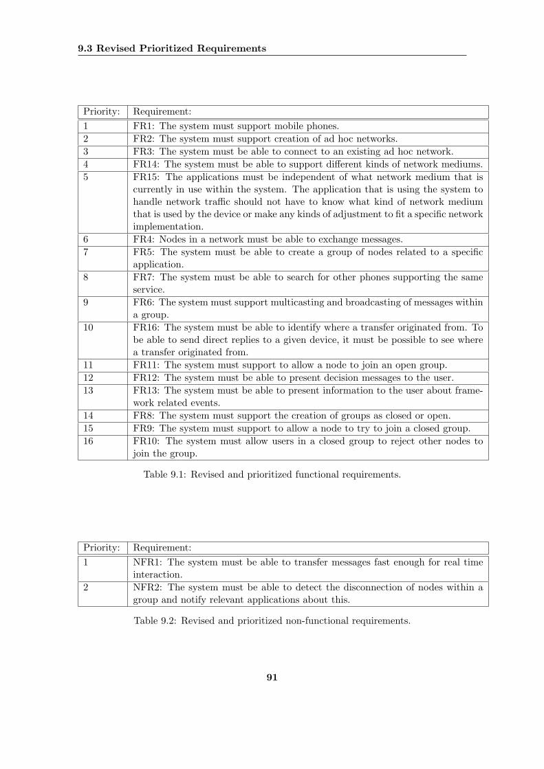
9.3 Revised Prioritized Requirements
Priority: Requirement:1 FR1: The system must support mobile phones.2 FR2: The system must support creation of ad hoc networks.3 FR3: The system must be able to connect to an existing ad hoc network.4 FR14: The system must be able to support different kinds of network mediums.5 FR15: The applications must be independent of what network medium that is
currently in use within the system. The application that is using the system tohandle network traffic should not have to know what kind of network mediumthat is used by the device or make any kinds of adjustment to fit a specific networkimplementation.
6 FR4: Nodes in a network must be able to exchange messages.7 FR5: The system must be able to create a group of nodes related to a specific
application.8 FR7: The system must be able to search for other phones supporting the same
service.9 FR6: The system must support multicasting and broadcasting of messages within
a group.10 FR16: The system must be able to identify where a transfer originated from. To
be able to send direct replies to a given device, it must be possible to see wherea transfer originated from.
11 FR11: The system must support to allow a node to join an open group.12 FR12: The system must be able to present decision messages to the user.13 FR13: The system must be able to present information to the user about frame-
work related events.14 FR8: The system must support the creation of groups as closed or open.15 FR9: The system must support to allow a node to try to join a closed group.16 FR10: The system must allow users in a closed group to reject other nodes to
join the group.
Table 9.1: Revised and prioritized functional requirements.
Priority: Requirement:1 NFR1: The system must be able to transfer messages fast enough for real time
interaction.2 NFR2: The system must be able to detect the disconnection of nodes within a
group and notify relevant applications about this.
Table 9.2: Revised and prioritized non-functional requirements.
91

Requirements
92

Part III
Design
93

94
Chapter 10
Designing the Framework
This chapter will present our proposed design for a framework for collaborative applicationson mobile phones. Parts of the design is inspired by the work of Sveen and Kirkhus in[30], but due to our revised requirements and limitations of scope we have taken the designinto a different direction.
We will begin by presenting the domain doncepts central to the understanding of ourdesign. From there we will move on to present an overview of the framework architec-ture and the actual framework design. Last, we will present the design of the Bluetoothimplementation of the network layer.
10.1 Domain Concepts
In our design, there are a few concepts that are essential for understanding the system.We will now provide a description of these concepts and the relationship between them.
First we will describe each concept by itself. We will then move on to explain which oneswill need a network specific implementation and how an application using the frameworkcan utilize the components.
Framework: The framework entity is the core entity of our framework and will be usedas an interface between the application and the rest of system. It manages resourcessuch as known peers, available network mediums, etc.
Node: A node is a logical representation of a peer, in our case a mobile phone runningthe framework.
Network: The network is an abstraction of the network layer. The applications willusually not use the the network instance directly but access it through the frameworkinstance.
Service: A service is connected to a specific application and supported by zero or morenodes.
95
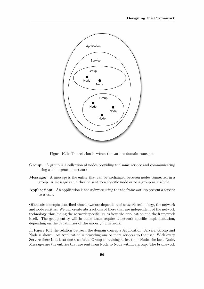
Designing the Framework
Application
Service
Group
Group
NodeNode
NodeNode
Node
Figure 10.1: The relation bewteen the variuos domain concepts.
Group: A group is a collection of nodes providing the same service and communicatingusing a homogeneous network.
Message: A message is the entity that can be exchanged between nodes connected in agroup. A message can either be sent to a specific node or to a group as a whole.
Application: An application is the software using the the framework to present a serviceto a user.
Of the six concepts described above, two are dependent of network technology, the networkand node entities. We will create abstractions of these that are independent of the networktechnology, thus hiding the network specific issues from the application and the frameworkitself. The group entity will in some cases require a network specific implementation,depending on the capabilities of the underlying network.
In Figure 10.1 the relation between the domain concepts Application, Service, Group andNode is shown. An Application is providing one or more services to the user. With everyService there is at least one associated Group containing at least one Node, the local Node.Messages are the entities that are sent from Node to Node within a group. The Framework
96
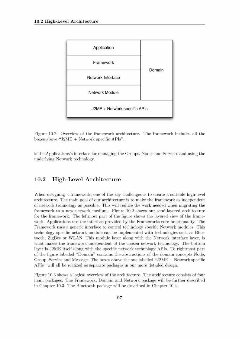
10.2 High-Level Architecture
J2ME + Network specific APIs
Network Module
Network Interface
Framework
Application
Domain
Figure 10.2: Overview of the framework architecture. The framework includes all theboxes above “J2ME + Network specific APIs”.
is the Applications’s interface for managing the Groups, Nodes and Services and using theunderlying Network technology.
10.2 High-Level Architecture
When designing a framework, one of the key challenges is to create a suitable high-levelarchitecture. The main goal of our architecture is to make the framework as independentof network technology as possible. This will reduce the work needed when migrating theframework to a new network medium. Figure 10.2 shows our semi-layered architecturefor the framework. The leftmost part of the figure shows the layered view of the frame-work. Applications use the interface provided by the Frameworks core functionality. TheFramework uses a generic interface to control technology specific Network modules. Thistechnology specific network module can be implemented with technologies such as Blue-tooth, ZigBee or WLAN. This module layer along with the Network interface layer, iswhat makes the framework independent of the chosen network technology. The bottomlayer is J2ME itself along with the specific network technology APIs. To rightmost partof the figure labelled “Domain” contains the abstractions of the domain concepts Node,Group, Service and Message. The boxes above the one labelled “J2ME + Network specificAPIs” will all be realized as separate packages in our more detailed design.
Figure 10.3 shows a logical overview of the architecture. The architecture consists of fourmain packages. The Framework, Domain and Network package will be further describedin Chapter 10.3. The Bluetooth package will be described in Chapter 10.4.
97
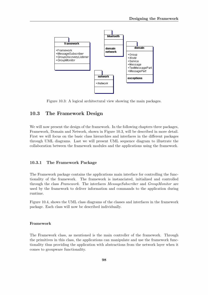
Designing the Framework
Figure 10.3: A logical architectural view showing the main packages.
10.3 The Framework Design
We will now present the design of the framework. In the following chapters three packages,Framework, Domain and Network, shown in Figure 10.3, will be described in more detail.First we will focus on the basic class hierarchies and interfaces in the different packagesthrough UML diagrams. Last we will present UML sequence diagram to illustrate thecollaboration between the framework modules and the applications using the framework.
10.3.1 The Framework Package
The Framework package contains the applications main interface for controlling the func-tionality of the framework. The framework is instanciated, initialized and controlledthrough the class Framework. The interfaces MessageSubscriber and GroupMonitor areused by the framework to deliver information and commands to the application duringruntime.
Figure 10.4, shows the UML class diagrams of the classes and interfaces in the frameworkpackage. Each class will now be described individually.
Framework
The Framework class, as mentioned is the main controller of the framework. Throughthe primitives in this class, the applications can manipulate and use the framework func-tionality thus providing the application with abstractions from the network layer when itcomes to groupware functionality.
98
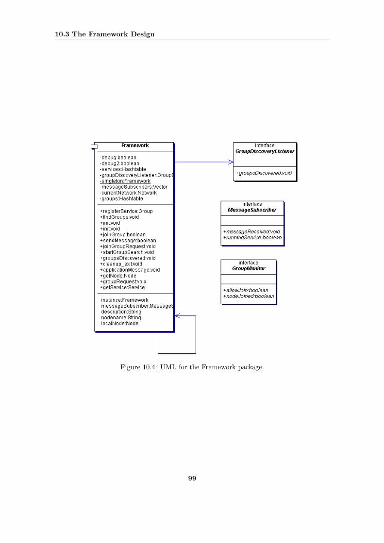
10.3 The Framework Design
Figure 10.4: UML for the Framework package.
99
Designing the Framework
GroupDiscoveryListener
The GroupDiscoveryListener interface is used for notifying application object that newgroups have been discovered. When the framework receives a message that lists groupsconnected to a service as a response to a service inquiry message, the method groupsDis-covered is called. It is then left up to the application how to handle this event.
GroupMonitor
The GroupMonitor interface provides an application with the means to control a group.By implementing this interface, an object can be asked to decide if a new node should beallowed to join the group or not. The GroupMonitor object will also be notified when newnodes join the groups.
MessageSubscriber
The MessageSubscriber interface enables the application to subscribe to messages arrivingat the local device. If a class implements this interface, it can be registered with theframework as a MessageSubscriber and thus be notified of incoming messages.
10.3.2 The Domain Package
The Domain package package provides abstractions for a lot of the concepts presented inChapter 10.1. Through the classes in this package, the applications can maintain a viewof their environment.
Figure 10.5, shows the UML class diagrams of the classes and interfaces in the domainpackage. Each class will now be described individually.
Service
The service provides information about the service that the applications using the frame-work provides. The service creates classes of applications enabling them to search for otherdevices running the same service, connect and communicate with them. An applicationshould always register a Service object with its Framework instanciation.
Node
A device running an application using the framework is represented as a Node. TheNode is an abstract class, thus hiding network specific properties from the application andenabling it to focus utterly on communicating with other applications.
100
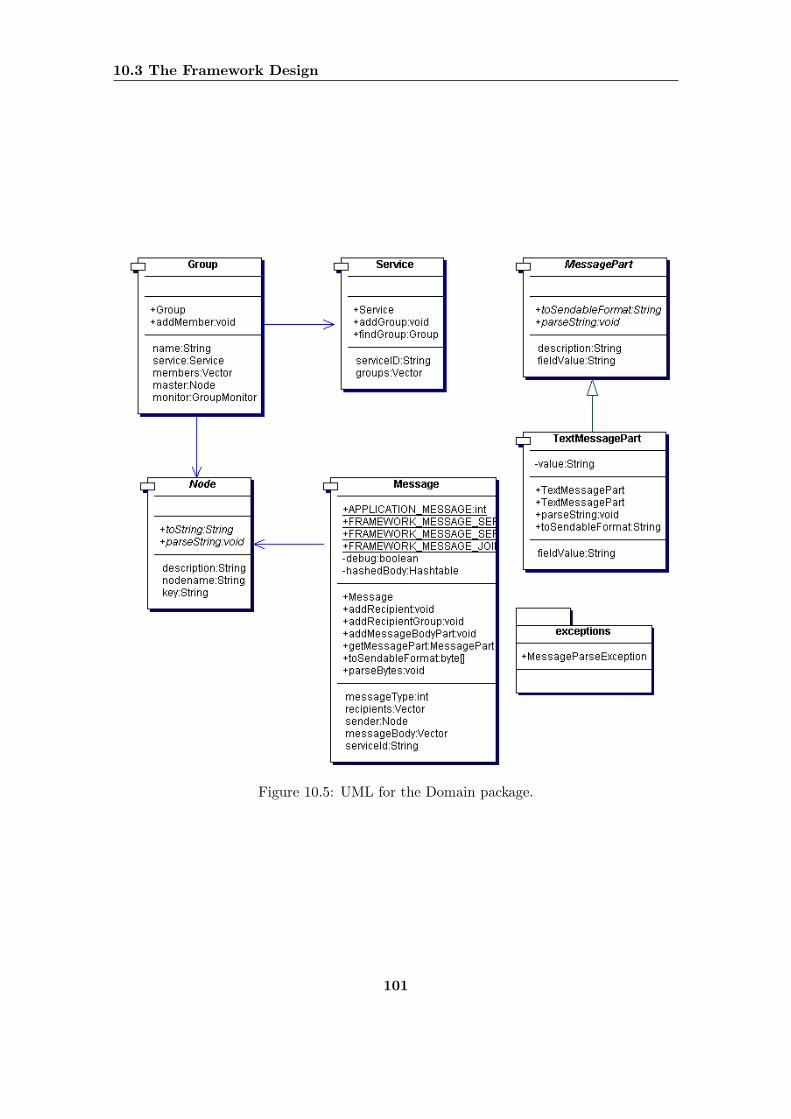
10.3 The Framework Design
Figure 10.5: UML for the Domain package.
101
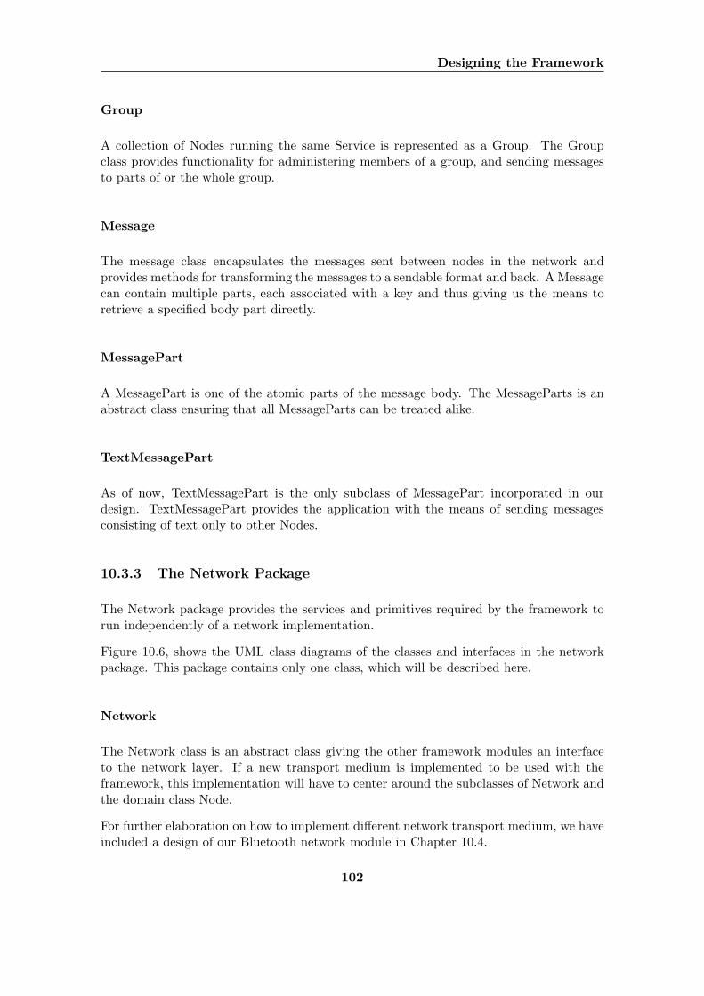
Designing the Framework
Group
A collection of Nodes running the same Service is represented as a Group. The Groupclass provides functionality for administering members of a group, and sending messagesto parts of or the whole group.
Message
The message class encapsulates the messages sent between nodes in the network andprovides methods for transforming the messages to a sendable format and back. A Messagecan contain multiple parts, each associated with a key and thus giving us the means toretrieve a specified body part directly.
MessagePart
A MessagePart is one of the atomic parts of the message body. The MessageParts is anabstract class ensuring that all MessageParts can be treated alike.
TextMessagePart
As of now, TextMessagePart is the only subclass of MessagePart incorporated in ourdesign. TextMessagePart provides the application with the means of sending messagesconsisting of text only to other Nodes.
10.3.3 The Network Package
The Network package provides the services and primitives required by the framework torun independently of a network implementation.
Figure 10.6, shows the UML class diagrams of the classes and interfaces in the networkpackage. This package contains only one class, which will be described here.
Network
The Network class is an abstract class giving the other framework modules an interfaceto the network layer. If a new transport medium is implemented to be used with theframework, this implementation will have to center around the subclasses of Network andthe domain class Node.
For further elaboration on how to implement different network transport medium, we haveincluded a design of our Bluetooth network module in Chapter 10.4.
102
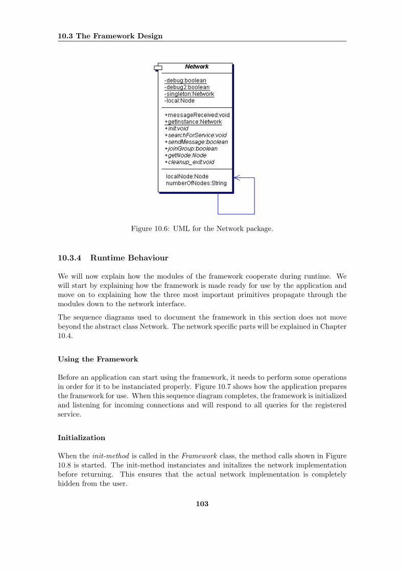
10.3 The Framework Design
Figure 10.6: UML for the Network package.
10.3.4 Runtime Behaviour
We will now explain how the modules of the framework cooperate during runtime. Wewill start by explaining how the framework is made ready for use by the application andmove on to explaining how the three most important primitives propagate through themodules down to the network interface.
The sequence diagrams used to document the framework in this section does not movebeyond the abstract class Network. The network specific parts will be explained in Chapter10.4.
Using the Framework
Before an application can start using the framework, it needs to perform some operationsin order for it to be instanciated properly. Figure 10.7 shows how the application preparesthe framework for use. When this sequence diagram completes, the framework is initializedand listening for incoming connections and will respond to all queries for the registeredservice.
Initialization
When the init-method is called in the Framework class, the method calls shown in Figure10.8 is started. The init-method instanciates and initalizes the network implementationbefore returning. This ensures that the actual network implementation is completelyhidden from the user.
103
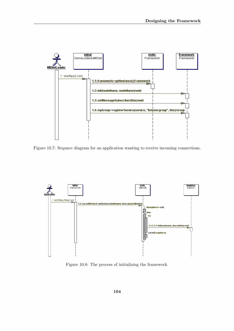
Designing the Framework
Figure 10.7: Sequnce diagram for an application wanting to receive incoming connections.
Figure 10.8: The process of initializing the framework.
104
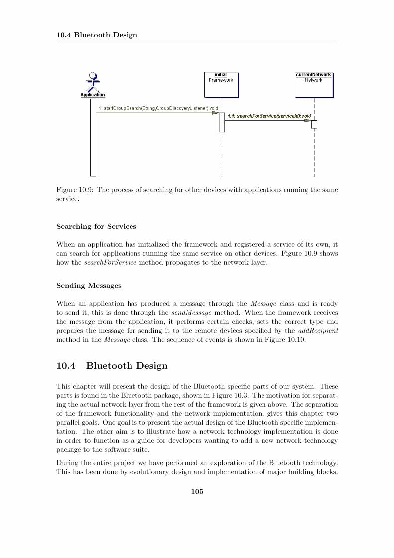
10.4 Bluetooth Design
Figure 10.9: The process of searching for other devices with applications running the sameservice.
Searching for Services
When an application has initialized the framework and registered a service of its own, itcan search for applications running the same service on other devices. Figure 10.9 showshow the searchForService method propagates to the network layer.
Sending Messages
When an application has produced a message through the Message class and is readyto send it, this is done through the sendMessage method. When the framework receivesthe message from the application, it performs certain checks, sets the correct type andprepares the message for sending it to the remote devices specified by the addRecipientmethod in the Message class. The sequence of events is shown in Figure 10.10.
10.4 Bluetooth Design
This chapter will present the design of the Bluetooth specific parts of our system. Theseparts is found in the Bluetooth package, shown in Figure 10.3. The motivation for separat-ing the actual network layer from the rest of the framework is given above. The separationof the framework functionality and the network implementation, gives this chapter twoparallel goals. One goal is to present the actual design of the Bluetooth specific implemen-tation. The other aim is to illustrate how a network technology implementation is donein order to function as a guide for developers wanting to add a new network technologypackage to the software suite.
During the entire project we have performed an exploration of the Bluetooth technology.This has been done by evolutionary design and implementation of major building blocks.
105
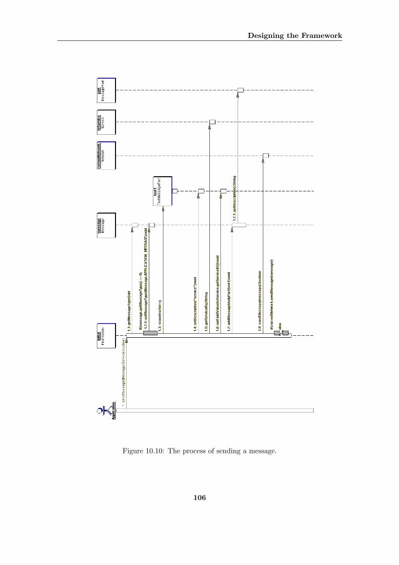
Designing the Framework
Figure 10.10: The process of sending a message.
106
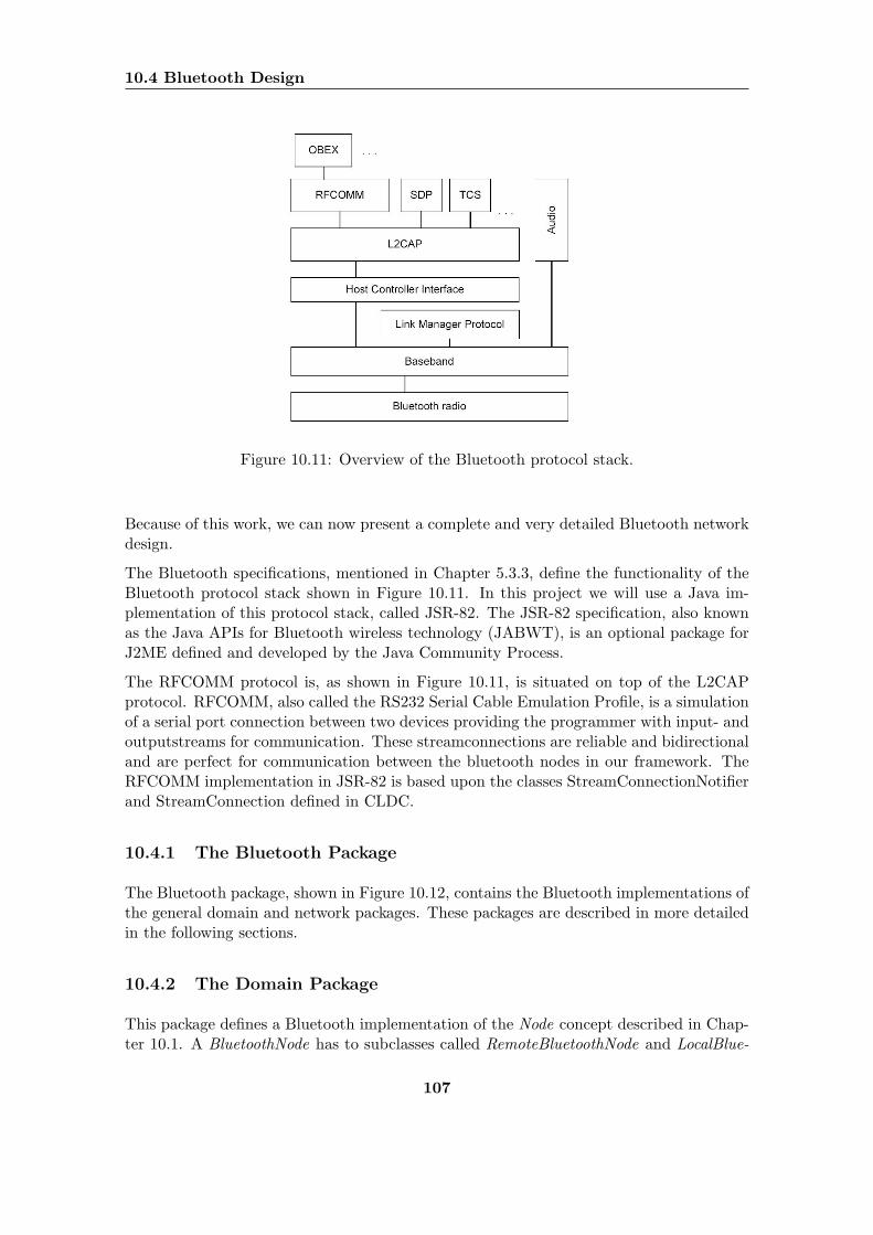
10.4 Bluetooth Design
Figure 10.11: Overview of the Bluetooth protocol stack.
Because of this work, we can now present a complete and very detailed Bluetooth networkdesign.
The Bluetooth specifications, mentioned in Chapter 5.3.3, define the functionality of theBluetooth protocol stack shown in Figure 10.11. In this project we will use a Java im-plementation of this protocol stack, called JSR-82. The JSR-82 specification, also knownas the Java APIs for Bluetooth wireless technology (JABWT), is an optional package forJ2ME defined and developed by the Java Community Process.
The RFCOMM protocol is, as shown in Figure 10.11, is situated on top of the L2CAPprotocol. RFCOMM, also called the RS232 Serial Cable Emulation Profile, is a simulationof a serial port connection between two devices providing the programmer with input- andoutputstreams for communication. These streamconnections are reliable and bidirectionaland are perfect for communication between the bluetooth nodes in our framework. TheRFCOMM implementation in JSR-82 is based upon the classes StreamConnectionNotifierand StreamConnection defined in CLDC.
10.4.1 The Bluetooth Package
The Bluetooth package, shown in Figure 10.12, contains the Bluetooth implementations ofthe general domain and network packages. These packages are described in more detailedin the following sections.
10.4.2 The Domain Package
This package defines a Bluetooth implementation of the Node concept described in Chap-ter 10.1. A BluetoothNode has to subclasses called RemoteBluetoothNode and LocalBlue-
107
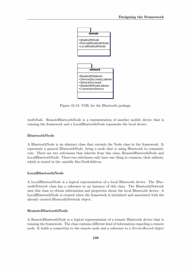
Designing the Framework
Figure 10.12: UML for the Bluetooth package.
toothNode. RemoteBluetoothNode is a representation of another mobile device that isrunning the framework and a LocalBluetoothNode represents the local device.
BluetoothNode
A BluetoothNode is an abstract class that extends the Node class in the framework. Itrepresents a general BluetoothNode, being a node that is using Bluetooth to communi-cate. There are two subclasses that inherits from this class, RemoteBluetoothNode andLocalBluetoothNode. These two subclasses only have one thing in common, their address,which is stored in the variable blueToothAddress.
LocalBluetoothNode
A LocalBluetootNode is a logical representation of a local Bluetooth device. The Blue-toothNetwork class has a reference to an instance of this class. The BluetoothNetworkuses this class to obtain information and properties about the local Bluetooth device. ALocalBluetoothNode is created when the framework is initialized and associated with thealready created BluetoothNetwork object.
RemoteBluetoothNode
A RemoteBluetoothNode is a logical representation of a remote Bluetooth device that isrunning the framework. The class contains different kind of information regarding a remotenode. It holds a connection to the remote node and a reference to a ServiceRecord object
108
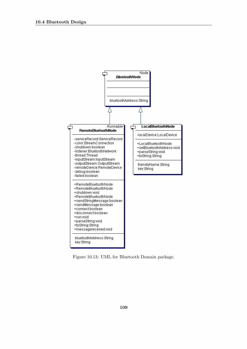
10.4 Bluetooth Design
Figure 10.13: UML for Bluetooth Domain package.
109
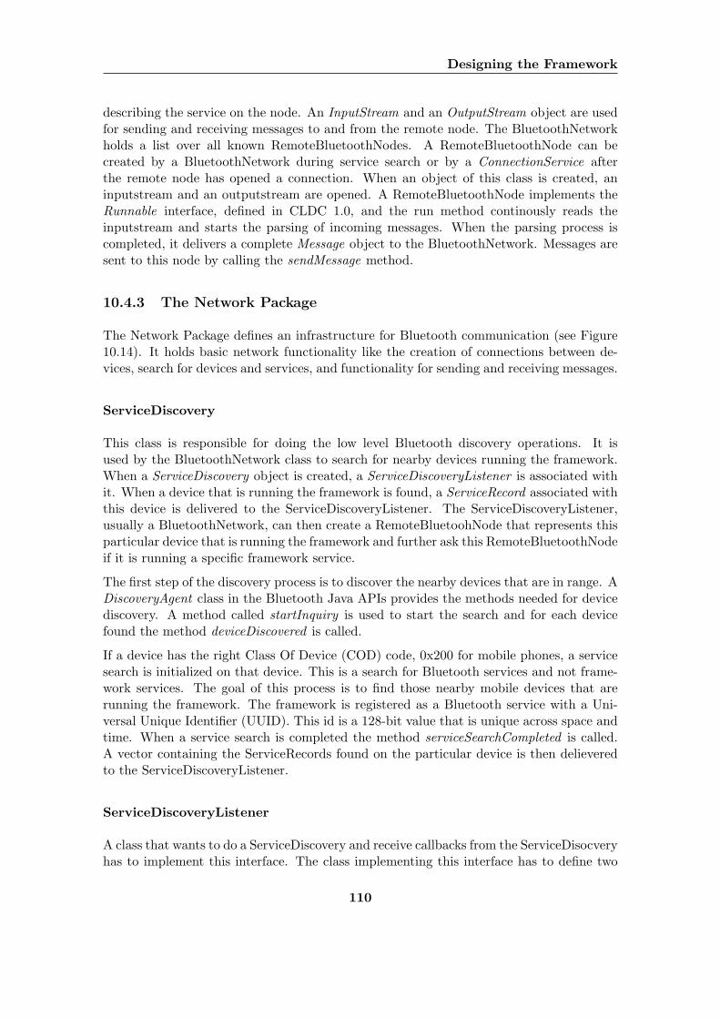
Designing the Framework
describing the service on the node. An InputStream and an OutputStream object are usedfor sending and receiving messages to and from the remote node. The BluetoothNetworkholds a list over all known RemoteBluetoothNodes. A RemoteBluetoothNode can becreated by a BluetoothNetwork during service search or by a ConnectionService afterthe remote node has opened a connection. When an object of this class is created, aninputstream and an outputstream are opened. A RemoteBluetoothNode implements theRunnable interface, defined in CLDC 1.0, and the run method continously reads theinputstream and starts the parsing of incoming messages. When the parsing process iscompleted, it delivers a complete Message object to the BluetoothNetwork. Messages aresent to this node by calling the sendMessage method.
10.4.3 The Network Package
The Network Package defines an infrastructure for Bluetooth communication (see Figure10.14). It holds basic network functionality like the creation of connections between de-vices, search for devices and services, and functionality for sending and receiving messages.
ServiceDiscovery
This class is responsible for doing the low level Bluetooth discovery operations. It isused by the BluetoothNetwork class to search for nearby devices running the framework.When a ServiceDiscovery object is created, a ServiceDiscoveryListener is associated withit. When a device that is running the framework is found, a ServiceRecord associated withthis device is delivered to the ServiceDiscoveryListener. The ServiceDiscoveryListener,usually a BluetoothNetwork, can then create a RemoteBluetoohNode that represents thisparticular device that is running the framework and further ask this RemoteBluetoothNodeif it is running a specific framework service.
The first step of the discovery process is to discover the nearby devices that are in range. ADiscoveryAgent class in the Bluetooth Java APIs provides the methods needed for devicediscovery. A method called startInquiry is used to start the search and for each devicefound the method deviceDiscovered is called.
If a device has the right Class Of Device (COD) code, 0x200 for mobile phones, a servicesearch is initialized on that device. This is a search for Bluetooth services and not frame-work services. The goal of this process is to find those nearby mobile devices that arerunning the framework. The framework is registered as a Bluetooth service with a Uni-versal Unique Identifier (UUID). This id is a 128-bit value that is unique across space andtime. When a service search is completed the method serviceSearchCompleted is called.A vector containing the ServiceRecords found on the particular device is then delieveredto the ServiceDiscoveryListener.
ServiceDiscoveryListener
A class that wants to do a ServiceDiscovery and receive callbacks from the ServiceDisocveryhas to implement this interface. The class implementing this interface has to define two
110
10.5 Prototype Applications
methods. A method for handling the completion of a service discovery and another methodfor dealing with errors.
BluetoothNodeListener
The BluetoothNodeListener interface enables the BluetoothNetwork to receive notificationsand callbacks from a RemoteBluetoothNode. The interface defines methods for registeringa node, receiving a message and handling a closed connection.
BluetoothNetwork
In this class all main network operations are executed or initialized. BluetoothNetworkis the main class of the Bluetooth network package. The class inherits from the abstractclass Network. This class holds a complete list of all known RemoteBluetoothNodes and areference to the LocalBluetoothNode. The BluetoothNetwork is used by the framework tosend messages, perform service searches, register nodes and monitoring and administeringthe status and threads specific to the Bluetooth module.
ConnectionService
When a BluetoothNetwork is initialized a ConnectionService is also initialized. Thereis a one-to-one dependency between BluetoothNetwotk and ConnectionService. When aConnectionService object is created, an RFCOMM server is initialized with a connectionstring based upon the framework UUID. This creation returns a StreamConnectionNoti-fier object. From here the ConnectionService runs continuously, using the StreamCon-nectionNotifer object to accept and open new connections. For each new connection aRemoteBluetoothNode is created. This RemoteBluetoothNode object is given a referenceto the BluetoothNetwork and the newly accepted connection.
10.5 Prototype Applications
In this section we present the design of two demo applications primarily created to testand demonstrate the functionality provided in the framework. DemoMIDlet ’s aim is topresent the bare minimum of an application connecting to another phone and sending amessage. ChatApp is a very simple chat application that lets two users exchange messagestyped on their phones in real time. In Chapter 7 we described three categories of mobilecollaborative applications. Those requiring user interaction, those performing the interac-tion with other devices automatically and those that automatically triggers collaborationthat requires further user interaction. The two demo applications presented here, repre-sent two of those categories. DemoMIDlet being automated and ChatApp requiring userinteraction.
111
Designing the Framework
10.5.1 DemoMIDlet
Figure 10.15, shows the UML diagram for the class DemoMIDlet. The functionality em-bedded in this application is the following, all done automatically:
• The application initializes the framework.
• The application registers a service called “demo”.
• The application then continuously searches for other devices running the same ser-vice.
• For each device found, the applications connects to the groups discovered and sendsan initial message to the remote device.
10.5.2 ChatApp
ChatApp, shown in Figure 10.16, is a more complex application than DemoMIDlet, tryingto illustrate some of the advantages the framework provides to the developer. In additionto searching for other devices running ChatApp and connecting to them, ChatApp doesthe following:
• Sends a message to the remote device, establishing nick names for each user.
• Allows the user to read messages sent from the local device in real time.
• Allows the user to type and send messages to remote devices in real time.
112
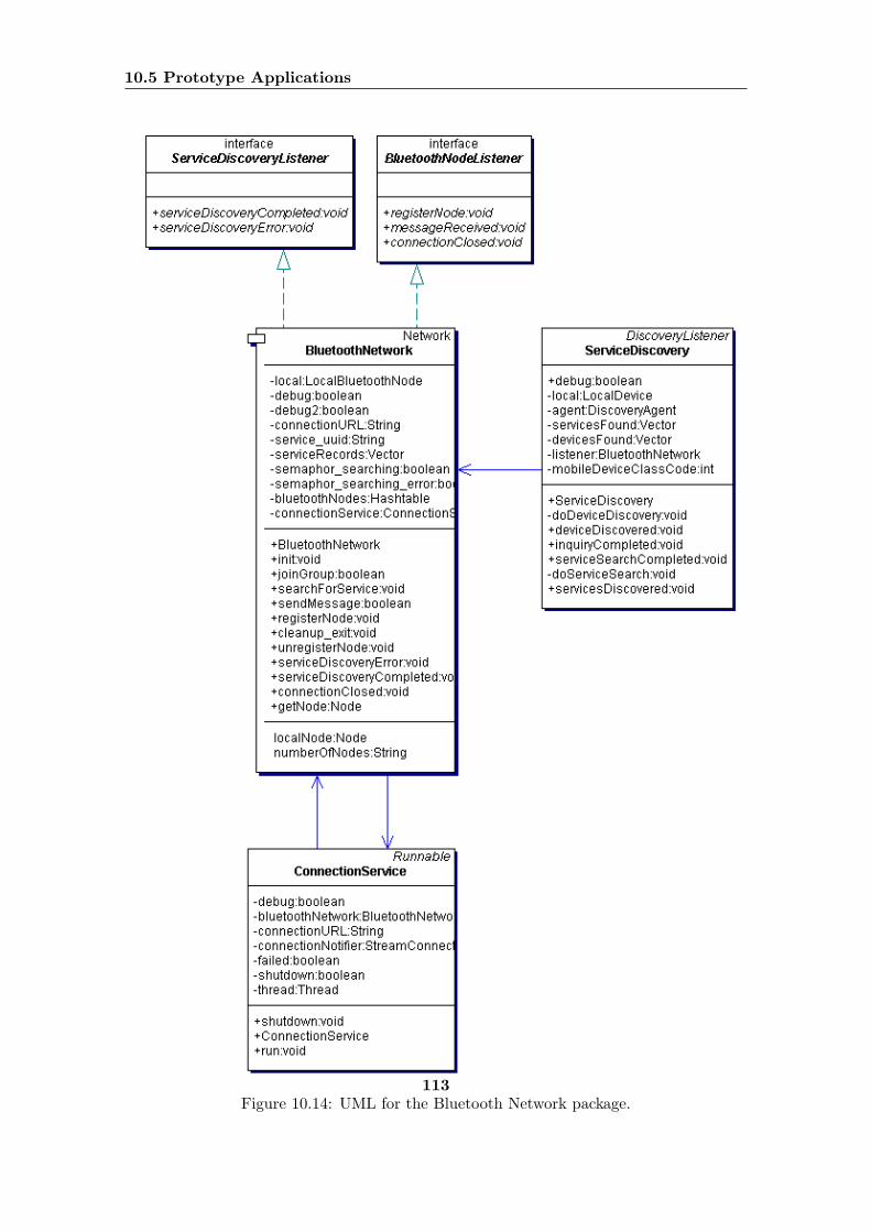
10.5 Prototype Applications
Figure 10.14: UML for the Bluetooth Network package.113
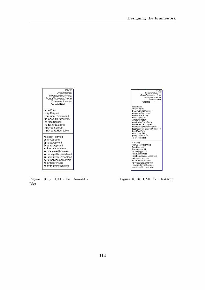
Designing the Framework
Figure 10.15: UML for DemoMI-Dlet
Figure 10.16: UML for ChatApp
114
Part IV
Implementation
115

116
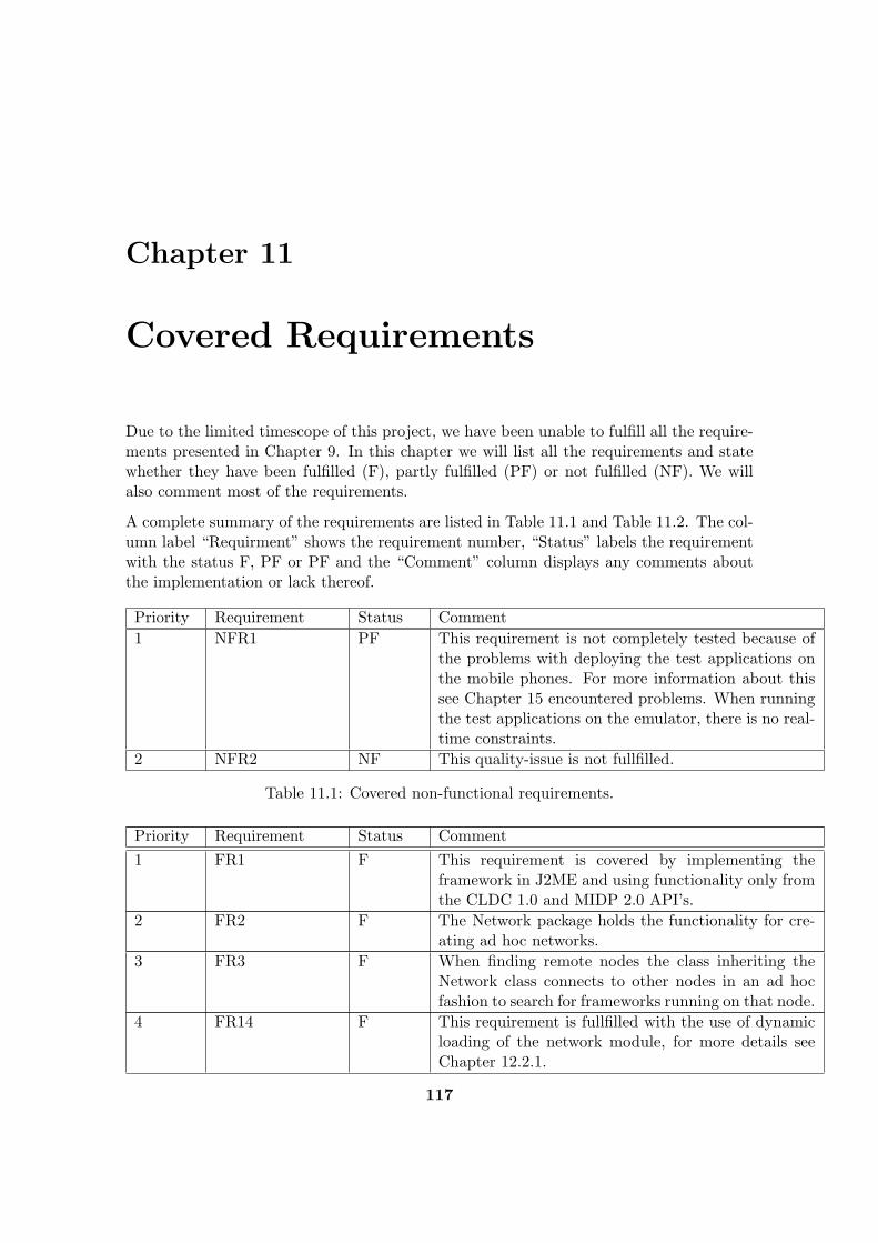
Chapter 11
Covered Requirements
Due to the limited timescope of this project, we have been unable to fulfill all the require-ments presented in Chapter 9. In this chapter we will list all the requirements and statewhether they have been fulfilled (F), partly fulfilled (PF) or not fulfilled (NF). We willalso comment most of the requirements.
A complete summary of the requirements are listed in Table 11.1 and Table 11.2. The col-umn label “Requirment” shows the requirement number, “Status” labels the requirementwith the status F, PF or PF and the “Comment” column displays any comments aboutthe implementation or lack thereof.
Priority Requirement Status Comment1 NFR1 PF This requirement is not completely tested because of
the problems with deploying the test applications onthe mobile phones. For more information about thissee Chapter 15 encountered problems. When runningthe test applications on the emulator, there is no real-time constraints.
2 NFR2 NF This quality-issue is not fullfilled.
Table 11.1: Covered non-functional requirements.
Priority Requirement Status Comment1 FR1 F This requirement is covered by implementing the
framework in J2ME and using functionality only fromthe CLDC 1.0 and MIDP 2.0 API’s.
2 FR2 F The Network package holds the functionality for cre-ating ad hoc networks.
3 FR3 F When finding remote nodes the class inheriting theNetwork class connects to other nodes in an ad hocfashion to search for frameworks running on that node.
4 FR14 F This requirement is fullfilled with the use of dynamicloading of the network module, for more details seeChapter 12.2.1.
117
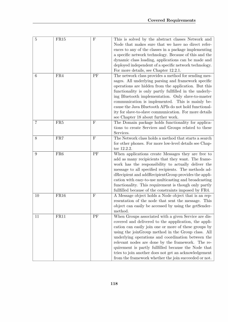
Covered Requirements
5 FR15 F This is solved by the abstract classes Network andNode that makes sure that we have no direct refer-ences to any of the classes in a package implementinga specific network technology. Because of this and thedynamic class loading, applications can be made anddeployed independent of a specific network technology.For more details, see Chapter 12.2.1.
6 FR4 PF The network class provides a method for sending mes-sages. All underlying parsing and framework specificoperations are hidden from the application. But thisfunctionality is only partly fullfilled in the underly-ing Bluetooth implementation. Only slave-to-mastercommunication is implemented. This is mainly be-cause the Java Bluetooth APIs do not hold functional-ity for slave-to-slave communication. For more detailssee Chapter 18 about further work.
7 FR5 F The Domain package holds functionality for applica-tions to create Services and Groups related to theseServices.
8 FR7 F The Network class holds a method that starts a searchfor other phones. For more low-level details see Chap-ter 12.2.2.
9 FR6 PF When applications create Messages they are free toadd as many recipicients that they want. The frame-work has the responsibility to actually deliver themessage to all specified recipients. The methods ad-dRecipient and addRecipientGroup provides the appli-cation with easy-to-use multicasting and broadcastingfunctionality. This requirement is though only partlyfullfilled because of the constraints imposed by FR4.
10 FR16 F A Message object holds a Node object that is an rep-resentation of the node that sent the message. Thisobject can easily be accessed by using the getSender-method.
11 FR11 PF When Groups associated with a given Service are dis-covered and delivered to the appplication, the appli-cation can easily join one or more of these groups byusing the joinGroup method in the Group class. Allunderlying operations and coordination between therelevant nodes are done by the framework. The re-quirement is partly fullfilled because the Node thattries to join another does not get an acknowledgementfrom the framework whether the join succeeded or not.
118
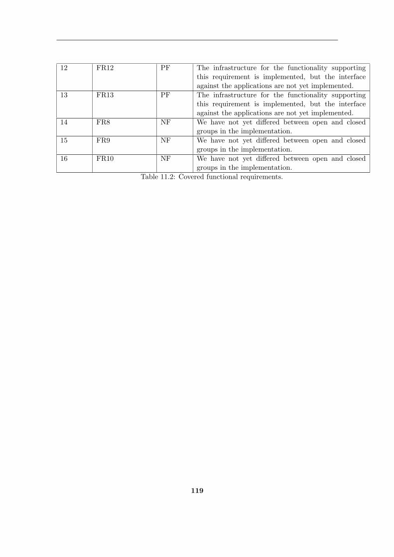
12 FR12 PF The infrastructure for the functionality supportingthis requirement is implemented, but the interfaceagainst the applications are not yet implemented.
13 FR13 PF The infrastructure for the functionality supportingthis requirement is implemented, but the interfaceagainst the applications are not yet implemented.
14 FR8 NF We have not yet differed between open and closedgroups in the implementation.
15 FR9 NF We have not yet differed between open and closedgroups in the implementation.
16 FR10 NF We have not yet differed between open and closedgroups in the implementation.
Table 11.2: Covered functional requirements.
119
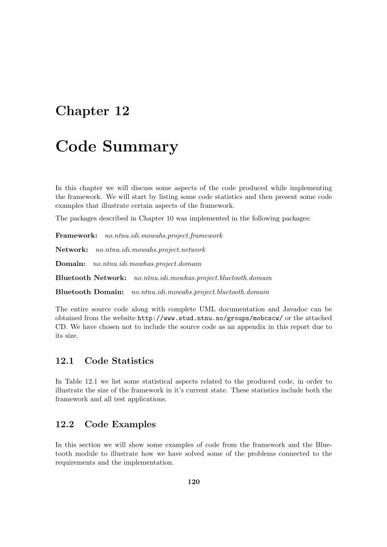
Chapter 12
Code Summary
In this chapter we will discuss some aspects of the code produced while implementingthe framework. We will start by listing some code statistics and then present some codeexamples that illustrate certain aspects of the framework.
The packages described in Chapter 10 was implemented in the following packages:
Framework: no.ntnu.idi.mowahs.project.framework
Network: no.ntnu.idi.mowahs.project.network
Domain: no.ntnu.idi.mowhas.project.domain
Bluetooth Network: no.ntnu.idi.mowhas.project.bluetooth.domain
Bluetooth Domain: no.ntnu.idi.mowahs.project.bluetooth.domain
The entire source code along with complete UML documentation and Javadoc can beobtained from the website http://www.stud.ntnu.no/groups/mobcscw/ or the attachedCD. We have chosen not to include the source code as an appendix in this report due toits size.
12.1 Code Statistics
In Table 12.1 we list some statistical aspects related to the produced code, in order toillustrate the size of the framework in it’s current state. These statistics include both theframework and all test applications.
12.2 Code Examples
In this section we will show some examples of code from the framework and the Blue-tooth module to illustrate how we have solved some of the problems connected to therequirements and the implementation.
120
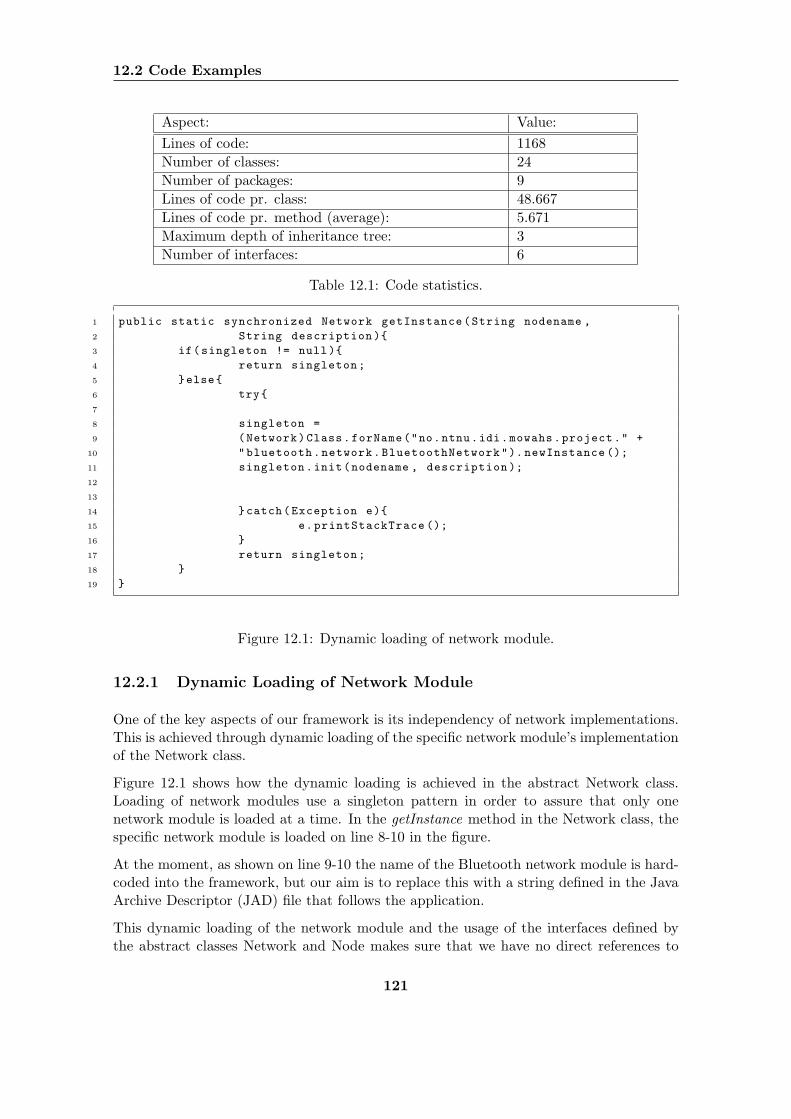
12.2 Code Examples
Aspect: Value:Lines of code: 1168Number of classes: 24Number of packages: 9Lines of code pr. class: 48.667Lines of code pr. method (average): 5.671Maximum depth of inheritance tree: 3Number of interfaces: 6
Table 12.1: Code statistics.
1 public static synchronized Network getInstance(String nodename ,
2 String description ){
3 if(singleton != null){
4 return singleton;
5 }else{
6 try{
7
8 singleton =
9 (Network)Class.forName("no.ntnu.idi.mowahs.project." +
10 "bluetooth.network.BluetoothNetwork"). newInstance ();
11 singleton.init(nodename , description );
12
13
14 }catch(Exception e){
15 e.printStackTrace ();
16 }
17 return singleton;
18 }
19 }
Figure 12.1: Dynamic loading of network module.
12.2.1 Dynamic Loading of Network Module
One of the key aspects of our framework is its independency of network implementations.This is achieved through dynamic loading of the specific network module’s implementationof the Network class.
Figure 12.1 shows how the dynamic loading is achieved in the abstract Network class.Loading of network modules use a singleton pattern in order to assure that only onenetwork module is loaded at a time. In the getInstance method in the Network class, thespecific network module is loaded on line 8-10 in the figure.
At the moment, as shown on line 9-10 the name of the Bluetooth network module is hard-coded into the framework, but our aim is to replace this with a string defined in the JavaArchive Descriptor (JAD) file that follows the application.
This dynamic loading of the network module and the usage of the interfaces defined bythe abstract classes Network and Node makes sure that we have no direct references to
121
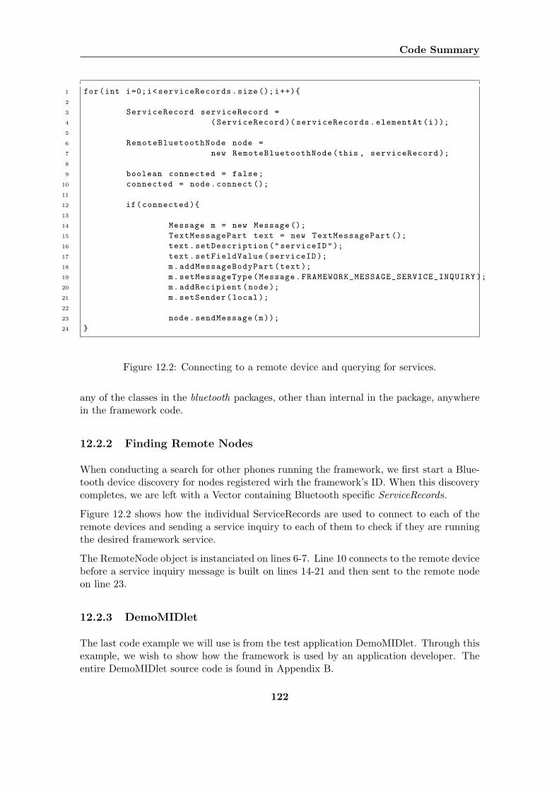
Code Summary
1 for(int i=0;i<serviceRecords.size ();i++){
2
3 ServiceRecord serviceRecord =
4 (ServiceRecord )( serviceRecords.elementAt(i));
5
6 RemoteBluetoothNode node =
7 new RemoteBluetoothNode(this , serviceRecord );
8
9 boolean connected = false;
10 connected = node.connect ();
11
12 if(connected ){
13
14 Message m = new Message ();
15 TextMessagePart text = new TextMessagePart ();
16 text.setDescription("serviceID");
17 text.setFieldValue(serviceID );
18 m.addMessageBodyPart(text);
19 m.setMessageType(Message.FRAMEWORK_MESSAGE_SERVICE_INQUIRY );
20 m.addRecipient(node);
21 m.setSender(local );
22
23 node.sendMessage(m));
24 }
Figure 12.2: Connecting to a remote device and querying for services.
any of the classes in the bluetooth packages, other than internal in the package, anywherein the framework code.
12.2.2 Finding Remote Nodes
When conducting a search for other phones running the framework, we first start a Blue-tooth device discovery for nodes registered wirh the framework’s ID. When this discoverycompletes, we are left with a Vector containing Bluetooth specific ServiceRecords.
Figure 12.2 shows how the individual ServiceRecords are used to connect to each of theremote devices and sending a service inquiry to each of them to check if they are runningthe desired framework service.
The RemoteNode object is instanciated on lines 6-7. Line 10 connects to the remote devicebefore a service inquiry message is built on lines 14-21 and then sent to the remote nodeon line 23.
12.2.3 DemoMIDlet
The last code example we will use is from the test application DemoMIDlet. Through thisexample, we wish to show how the framework is used by an application developer. Theentire DemoMIDlet source code is found in Appendix B.
122
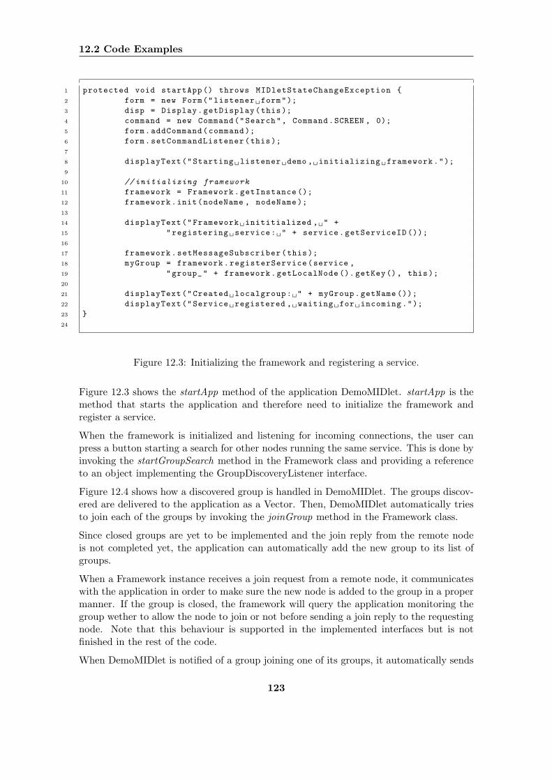
12.2 Code Examples
1 protected void startApp () throws MIDletStateChangeException {
2 form = new Form("listener form");
3 disp = Display.getDisplay(this);
4 command = new Command("Search", Command.SCREEN , 0);
5 form.addCommand(command );
6 form.setCommandListener(this);
7
8 displayText("Starting listener demo , initializing framework.");
9
10 // initializing framework
11 framework = Framework.getInstance ();
12 framework.init(nodeName , nodeName );
13
14 displayText("Framework inititialized , " +
15 "registering service: " + service.getServiceID ());
16
17 framework.setMessageSubscriber(this);
18 myGroup = framework.registerService(service ,
19 "group_" + framework.getLocalNode (). getKey(), this);
20
21 displayText("Created localgroup: " + myGroup.getName ());
22 displayText("Service registered , waiting for incoming.");
23 }
24
Figure 12.3: Initializing the framework and registering a service.
Figure 12.3 shows the startApp method of the application DemoMIDlet. startApp is themethod that starts the application and therefore need to initialize the framework andregister a service.
When the framework is initialized and listening for incoming connections, the user canpress a button starting a search for other nodes running the same service. This is done byinvoking the startGroupSearch method in the Framework class and providing a referenceto an object implementing the GroupDiscoveryListener interface.
Figure 12.4 shows how a discovered group is handled in DemoMIDlet. The groups discov-ered are delivered to the application as a Vector. Then, DemoMIDlet automatically triesto join each of the groups by invoking the joinGroup method in the Framework class.
Since closed groups are yet to be implemented and the join reply from the remote nodeis not completed yet, the application can automatically add the new group to its list ofgroups.
When a Framework instance receives a join request from a remote node, it communicateswith the application in order to make sure the new node is added to the group in a propermanner. If the group is closed, the framework will query the application monitoring thegroup wether to allow the node to join or not before sending a join reply to the requestingnode. Note that this behaviour is supported in the implemented interfaces but is notfinished in the rest of the code.
When DemoMIDlet is notified of a group joining one of its groups, it automatically sends
123
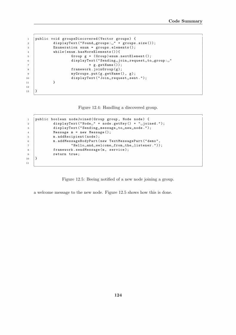
Code Summary
1 public void groupsDiscovered(Vector groups) {
2 displayText("Found groups: " + groups.size ());
3 Enumeration enum = groups.elements ();
4 while(enum.hasMoreElements ()){
5 Group g = (Group)enum.nextElement ();
6 displayText("Sending join request to group: "
7 + g.getName ());
8 framework.joinGroup(g);
9 myGroups.put(g.getName(), g);
10 displayText("Join request sent.");
11 }
12
13 }
Figure 12.4: Handling a discovered group.
1 public boolean nodeJoined(Group group , Node node) {
2 displayText("Node " + node.getKey () + " joined.");
3 displayText("Sending message to new node.");
4 Message m = new Message ();
5 m.addRecipient(node);
6 m.addMessageBodyPart(new TextMessagePart("demo",
7 "Hello and welcome from the listener."));
8 framework.sendMessage(m, service );
9 return true;
10 }
11
Figure 12.5: Beeing notified of a new node joining a group.
a welcome message to the new node. Figure 12.5 shows how this is done.
124
Chapter 13
Testing
According to our project process model, described in Chapter 2, our development andimplementation has been carried out iteratively. Functionality and design have evolvedthrough a set of iterations. During this process a lot of testing has been done. The testinghas been conducted in two different ways:
Using software emulating the phones behaviour: We have used The Nokia Devel-oper Kit to emulate the phones behaviour. We chose this emulator mainly becauseit includes functionality for emulating Bluetooth connections between phones andbecause it easily integrates with Eclipse as a plug-in.
Testing on Nokia 6600 and Sony Ericsson P900: Testing on the phones themselvesrevealed vulnerabilities in the phones software and hardware. Testing on the phonesalso gave us the possibility to try out the actual network technology and find outhow it worked along with our framework.
Testing the software on the phones was a time consuming process that involved five dif-ferent steps:
1. Compiling the code
2. Packaging of the code into a executable jar-file
3. Sending the jar-file using Bluetooth to the phones
4. Installing the jar-file on the phones
5. Running the jar-file on the phones
To save time we used the emulator to test the code in parallel with the implementationof a specific class or function. When a specific part or functionality was completed andran perfectly on the emulator we packaged the code, sent it to the phones and tested itout. The testing on the phones themselves often revealed problems. This is first of allbecause an emulator runs the software in a totally different environment. The emulator has
125
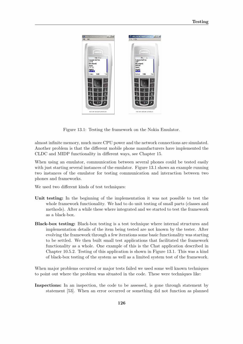
Testing
Figure 13.1: Testing the framework on the Nokia Emulator.
almost infinite memory, much more CPU power and the network connections are simulated.Another problem is that the different mobile phone manufacturers have implemented theCLDC and MIDP functionality in different ways, see Chapter 15.
When using an emulator, communication between several phones could be tested easilywith just starting several instances of the emulator. Figure 13.1 shows an example runningtwo instances of the emulator for testing communication and interaction between twophones and frameworks.
We used two different kinds of test techniques:
Unit testing: In the beginning of the implementation it was not possible to test thewhole framework functionality. We had to do unit testing of small parts (classes andmethods). After a while these where integrated and we started to test the frameworkas a black-box.
Black-box testing: Black-box testing is a test technique where internal structures andimplementation details of the item being tested are not known by the tester. Afterevolving the framework through a few iterations some basic functionality was startingto be settled. We then built small test applications that facilitated the frameworkfunctionality as a whole. One example of this is the Chat application described inChapter 10.5.2. Testing of this application is shown in Figure 13.1. This was a kindof black-box testing of the system as well as a limited system test of the framework.
When major problems occurred or major tests failed we used some well known techniquesto point out where the problem was situated in the code. These were techniques like:
Inspections: In an inspection, the code to be assessed, is gone through statement bystatement [53]. When an error occurred or something did not function as planned
126

we pointed out which class or method that could be the problem and then did aninspection of that particular code.
Walkthroughs: A walkthrough is a manual simulation of the code using test data. Weused this technique before and after testing to discover errors and to foresee problems.
By using these techniques we safed a lot of time during the test and implementationphases.
127
Chapter 14
Tool Evaluation
For designing, implementing and testing the framework, we have used the tools listed inChapter 2. We will now give a summary of how our experiences with these tools havebeen and how they have helped us in our work.
14.1 Eclipse
Eclipse has been our primary platform for writing code and also testing the framework onemulators. Eclipse has built in support for writing source code with Java syntax with codecompletion and on the fly compiling giving us instant notifications when errors appear inour source code. In addition to this, Eclipse has support for using only the CLDC, MIDPand JSR-82 class libraries as references, thus ensuring that whatever we wrote in Eclipseactually would compile for J2ME. We will get back to how the framework was tested inChapter 14.3.
We have also used the ecleTex plugin for Eclipse for writing the LATEXcode for this report.Although ecleTex currently is in version 0.0.3 and therefore quite unstable, it has providedus with syntax coloring and code completion for writing LATEXas well.
Eclipse also has integrated support for CVS, which has helped us a lot. Both in keepingour work synchronized as well as the security involved in the fact that the CVS server weused is backed up at least once every day.
14.2 Borland Together Control Center
Borland TCC worked fine running as a standalone application modelling the software thatwe later modified in Eclipse. Our only problem with Borland TCC was that it is extremelydemanding when it comes to system resources. This caused Borland TCC to executequite slowly on our workstations so we decided to try another product, EclipseUML1.EclipseUML was much faster and more responsive during execution, but was insufficient
1http://www.omondo.com
128
14.3 Emulators
in many other ways, e.g. for exporting the class diagrams for inclusion in this report. Wesoon found out that Borland TCC best suited our need and migrated back to using it andended up using Borland TCC for about 85% of the modelling work.
14.3 Emulators
On Microsoft Windows, the Nokia Developer Kit could be installed as a plugin for Eclipse.This plugin was our primary test instance, running the applications and simulating theBluetooth stack. One of the drawbacks we found about the Nokia Developer Kit wasthat it did not display console messages when Exceptions were thrown during runtime,making the debugging process quite tedious. The other drawback was that the applicationspackaged with the Nokia Developer Kit could not be installed on the mobile phones.
Since we were unable to package the applications with the Nokia Developer Kit, we hadto use another emulator for this job. Our choice was the Sony Ericsson Wireless Toolkit.The Sony Ericsson Wireless Toolkit packaged all the applications without problems andthe packages installed seamlessly on the mobile phones.
The ideal situation here would of course have been to use one emulator only for bothtesting and packaging, but unfortunately the Sony Ericsson Wireless Toolkit did not havesupport for emulating Bluetooth software and was therefore inadequate alone.
129

Tool Evaluation
130

Part V
Evaluation
131

132
Chapter 15
Encountered Problems
This chapter discusses the problems we have encountered during the lifetime of the project.These problems are either due to underestimated complexity in the problem domain ortechnical limitations in the technologies we have used.
15.1 The Mobile Phones
During implementation and testing we encountered problems directly related to runningsoftware on the mobile phones. These problems will be discussed here.
15.1.1 Mobile Phones versus Emulators
All our test applications have been error free when running on the Nokia Developer KitPhone Emulator. We found however that having software that ran perfectly on the emu-lator did not guarantee that it would run on mobile phones.
One of the main problems was that the applications freezed after receiving input from theuser. Applications searching for other devices and communicating with remote devicesautomatically had no problems, they exchanged the messages they were set to exchange.If we then modified one of these applications requiring the user to press a button in orderto trigger the rest of the automatic events, the application would freeze.
Due to time limitations we were unable to solve this problem, but we have some theoriesas to why this happens. We think that it most likely has to do with the stack size availableon J2ME on the mobile phones. We think that the extra method invocations introducedby the user pushing a button might actually cause some sort of stack overflow, causingone of the applications threads to die and thus freezing the application.
15.1.2 The Sony Ericsson Bluetooth Implementation
From early on in the project period, we were writing test software in order to explore theBluetooth API and learn how to use it. When trying to run these test programs on the
133
Encountered Problems
two phones we had at our disposal, the device discovery procedures only worked on theNokia 6600. The Sony Ericsson P900 always returned from the device discovery with avalue indicating discovery failure.
We were quite puzzled with this, but after some debugging we found that the Sony Ericssonimplementation of the JSR-82 Bluetooth API has switched two integer values. Accordingto JSR-82, a successful device discovery returns one value and a failure returns anothervalue. On the Sony Ericsson phone, these two values seemed to be opposite of what thespecification said. Different discussion forum threads we found at J2ME developer sitesconfirmed our suspicion.
Our conclusion when it comes to this problem is that the Sony Ericsson J2ME Bluetoothimplementation is not correct according to the specification.
15.2 Bluetooth
The current Bluetooth specification does not support slave to slave communication in apiconet. All messages going from one slave device to another must go through the masterdevice and be routed to the correct slave. This requires some sort of routing algorithm,which we did not have time to implement at this time. However, the framework currentlyhas support for communication between slave members of a group through establishingoverlapping piconets, but if one of the slave members is out of reach from at least one ofthe other slave members, this strategy will not work.
134
Chapter 16
Own Contribution
This chapter summarizes the contribution made by us through this project:
Classification matrix for mobile collaborative scenarios In Chapter 7 we defineda two dimensional classification matrix used to classify collaborative applicationsand scenarios based on PAN technology. The first dimension, called advanced P2Pfunctionality, dealt with wether or not the scenario or application requires advancedP2P functionality such as a routing algorithm or not, in other words piconet orscatternet communication. The second dimension set measured to what degree theuser interacts with the application or are involved in the scenario.
By defining and using this matrix for classification, we found a way to classify sce-narios made by others and a way to clearly define the scope of our project.
Scenarios: We have contributed with five scenarios that show possible usages of mobilecollaborative applications. These scenarios show how people can use their mobilephones together with a PAN technology to take part in collaborative activities.We have created scenarios based on automatic communication between devices andscenarios where people initially triggers the activities.
Requirements: Extracted from our scenarios we have contributed with a set of functionaland non-functional requirements that a framework for mobile collaboration usingPAN technology should be based on.
Domain concepts: In Chapter 10, we defined some domain concepts that laid down thefoundation for our framework design. These terms and definitions may be used byresearchers and other participants in the research field to explore and discuss relatedproblems.
Framework design and implementation: We have iteratively and evolutionary de-signed a framework for mobile collaboration on mobile phones. The framework isdesigned to be as generic as possible and to be independent of the underlying net-work technology. The framework takes care of the network infrastructure, handlesthe communication between the nodes in the network and provides an interface fordevelopers of applications. The framework is partly implemented, as described inChapter 11.
135

Own Contribution
Bluetooth network design: A complete Bluetooth communication and network infras-tructure has been designed and implemented using the Java APIs for Bluetooth(JSR-82). This Bluetooth design and implementation works as an example of aPAN technology that can be used by the framework.
Prototype applications: Two prototype example applications have been designed us-ing the partly implemented framework. These applications represents two of thescenario categories. The ChatApp application, see Chapter 10.5.2, is an exampleof applications requiring user interaction. The DemoMidlet , see Chapter 10.5.1, isan example of applications that facilitate automatic communication between mobiledevices.
136
Chapter 17
Conclusions
Our goal in this project was to create a useful, generic framework for collaborative appli-cations on mobile phones and test this to see if it actually worked.
We have implemented a proof-of-concept framework and demonstrated its functionalitythrough demo applications. Our design and implementation uses a layered approach toensure network technology independence and abstraction of the more complex APIs andadvanced infrastructure concerns. The three main layers are the network module, thenetwork interface and the framework. The framework and network interface layers are partof the total framework software, while the network module is a pluggable implementationof a specific network technology. In addition to this, the framework software has a modulehandling central domain concepts such as Service, Node, Group and Message. In thenetwork module layer we have implemented a Bluetooth network module, thus provingthat dynamic loading of network modules is possible.
Even though we have been unable to run all the applications on mobile phones, we haveshown that such a framework can work and has practical usage for developers of mobilecollaborative applications. The source code for the demo applications shows how mucha framework can simplify the handling of infrastructure and common concepts in suchapplications. All network specific events and synchronization of data irrelevant to theuser are hidden from the application behind a simple interface.
Compared to the related projects we discussed in Chapter 4, our framework is quite unique.No other implementations exist that are as complete as ours and that run on J2ME. Thiswas further confirmed when the Java Community Process initialized a project on the2nd of November 2004 that addresses the same problems as our framework, see JavaSpecification Requests (JSR) 259: Ad Hoc Networking API1. The purpose of this JSR isto define an API that enables communication between mobile devices in a P2P ad hocnetwork environment. Major industry actors as Ericsson, Nokia, IBM and Siemens areinvolved in this project.
As mentioned in Chapter 1, this project has been quite explorative in nature. In order tolearn as much as possible from our problem domain and to achieve as many of our goals
1http://www.jcp.org/en/jsr/detail?id=259
137
Conclusions
as possible, we chose to use a work model were we started by fanning out in our prestudybefore setting our specific focus, creating usage scenarios, uncovering requirements andthen using an iterative model to develop the framework with example applications. Wehave found that the chosen work model, has worked quite well.
Specifically we would like to mention two aspects concerning our work model. The firstbeing the advantages we achieved by fanning out to cover a quite broad range of domainconcepts, technologies and related projects in our prestudy. This enabled us to make theproper choices when setting our focus and gave us a good understanding of our problemdomain.
The second aspect of our work model is the iterative development model. Working initerations gave us the benefit of being able to test our design along the way. As soon as anew feature had been designed, we tried to implement it and test it to see if our solutionswould actually work. This method enabled us to discover design flaws as early as possibleand reduced the project risks, since we were working with technologies we were unfamiliarwith.
During our work on this project, we have learned a lot, especially when it comes to howto design a generic framework using object oriented techniques. Framework design andimplementation introduces new challenges when it comes to the use of polimorphy betweenclasses. We have grown more comfortable with using modelling tools more actively in thesoftware development process and have more experience when it comes to using scenariosfor requirements elaboration.
138
Chapter 18
Future Work
This chapter describes some of the areas we see as possible future work related to theframework and prototype applications.
18.1 Framework Design and Implementation
The design of the entire framework is not complete. It covers most of the requirementspresented in Chapter 9, but will need to be expanded. We will now discuss future work onthe design and implementation related to functionality, optimalization and last reliability.
18.1.1 Functionality
First of all, the requirements described in Chapter 11 that have not been fulfilled needsto be designed and implemented.
At the moment, only messages containing simple, text message parts not containing new-line characters are supported. In the future, support for different message parts should beadded, e.g. binary data and text messages containing new-line characters.
The Bluetooth implementations for J2ME in their current versions do not support directcommunication between slave devices in a piconet. Routing support will have to be im-plemented in the framework in order for the master device to be able to route messagesbetween the slave nodes and allow for slave-to-slave communication. Implementing thisrouting algorithm will automatically add support for multicasting and broadcasting ofmessages on a piconet since the Message class already has support for multiple recipients.When implementing the routing functionality, it may be considered to use some kind ofload balancing to balance the battery consumption of the master node. An approach sim-ilar to the one proposed in [10], where the the group members in a piconet continuouslyswap the master role, may be used.
139
Future Work
18.1.2 Optimalization
At the moment, some method calls are blocking. E.g. the searchForService method inframework blocks until the entire discovery process is completed in the network layer. Thisshould be changed to make it a non-blocking call in order to increase performance.
Performance can also be increased with a higher degree of parallel operations. This increasein parallelity will probably introduce more listener patterns in the design and code.
At the moment, there is no support for parallel service searches. Support for this will haveto be added to the framework, and be implemented in the Bluetooth network module.
The network modules can cache the devices discovered during a service search to makethe next searches faster. This caching will be specific to the network modules and willhave to be implemented in the Bluetooth module.
18.1.3 Reliability
The implementation existing today does not pay much attention to exception and errorhandling internally. In order to increase the reliability of the framework this will have tobe improved. For instance handling of disconnections due to nodes leaving transmissionrange or going down needs to be handled.
Some network mediums and network devices have a limit when it comes to how manyconnections they can handle. For instance, some Bluetooth devices have a limit on howmany connections they can handle and connection attempts beyond these will fail. Theframework needs to have support for running on devices with such limits and be able toinform the user of problems connected to this limit.
18.2 Building Applications
We hope to improve the framework and fix the problems preventing it from running onthe mobile phones today. As soon as this is done, a portfolio of applications can be builtand tested on users in a real environment. This form of testing will hopefully lead to threethings; research in the field of mobile collaborative applications, uncovering of weaknessesand strengths in the framework for further development and ideas for new applicationsthat can be built and tested.
140
Part VI
Appendix
141

142
Appendix A
Dictionary
This section will describe the concepts and terms necessary to gain a good understandingof our problem domain. The list is sorted alphabetically by abbreviation where available.
Bluetooth An open standard for wireless transmission of voice and data between mobiledevices in a PAN.
CSCW Computer Supported Cooperative Work. The CSCW field deals with the use ofcomputers to support cooperation between people.
Firewire A wired protocol for connecting devices in a PAN.
GPRS General Packet Radio Servcie. A layer on top of GSM for sending digital data toand from mobile devices.
GSM Global System for Mobile communication. The most widely used standard formobile communication today.
IEEE Institute of Electrical and Electronics Engineers. An organization providing stan-dards to the technical society.
IP Internet Protocol. The standard for communication on the internet.
J2ME Java 2 Micro Edition. J2ME is a development platform owned and maintained bySun Microsystems aimed at small and limited devices. Today most mobile phoneshave support for running J2ME applications.
JSR-82 The standard APIs for Bluetooth on mobile phones.
JXME A JXTA version for J2ME.
JXTA A project for creating a standard way of interconnecting computers in a P2Pnetwork independently of platform.
LAN Local Area Network. A LAN is used for connecting computers in a network.
143
Dictionary
MANET Mobile Ad Hoc NETworks. Mobile networks that are spontaneous, self-configuringand wireless with no fixed infrastructure.
P2P Peer-to-Peer. Interconnected computational devices working together as equals toserve a function.
PAN Personal Area Network. A PAN is mainly used for connecting devices within alimited area with a radius of a few meters. Example devices forming a PAN arelaptop-computers, printers and mobile phones and various peripheral devices such askeyboards and mice. A PAN is smaller than a LAN and often has limited bandwidth.
RFCOMM RS232 Serial Cable Emulation Profile). A Bluetooth transport protocol inthe core protocol stack simulating a serial port connection.
USB Universal Serial Bus. A wired protocol for interconnecting devices in a PAN.
UMTS Universal Mobile Telecommunication Service. The next generation of mobilecommunication systems.
WLAN A wireless version of LAN.
WPAN A wireless version of PAN.
144
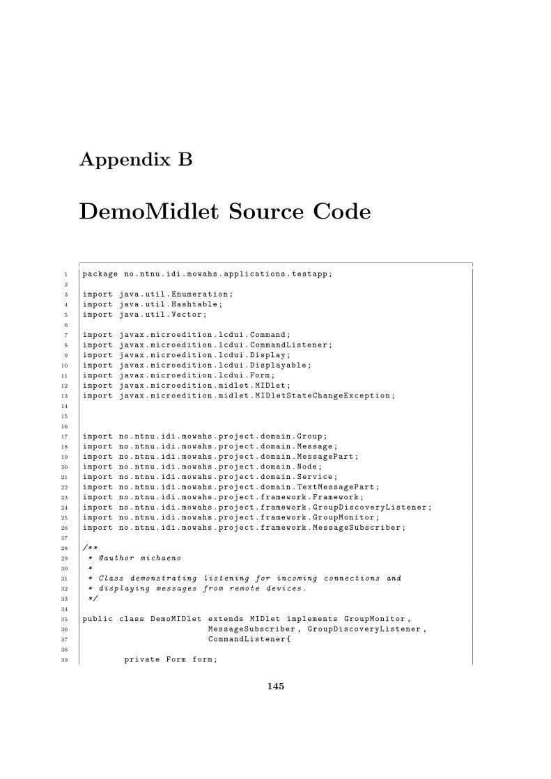
Appendix B
DemoMidlet Source Code
1 package no.ntnu.idi.mowahs.applications.testapp;
2
3 import java.util.Enumeration;
4 import java.util.Hashtable;
5 import java.util.Vector;
6
7 import javax.microedition.lcdui.Command;
8 import javax.microedition.lcdui.CommandListener;
9 import javax.microedition.lcdui.Display;
10 import javax.microedition.lcdui.Displayable;
11 import javax.microedition.lcdui.Form;
12 import javax.microedition.midlet.MIDlet;
13 import javax.microedition.midlet.MIDletStateChangeException;
14
15
16
17 import no.ntnu.idi.mowahs.project.domain.Group;
18 import no.ntnu.idi.mowahs.project.domain.Message;
19 import no.ntnu.idi.mowahs.project.domain.MessagePart;
20 import no.ntnu.idi.mowahs.project.domain.Node;
21 import no.ntnu.idi.mowahs.project.domain.Service;
22 import no.ntnu.idi.mowahs.project.domain.TextMessagePart;
23 import no.ntnu.idi.mowahs.project.framework.Framework;
24 import no.ntnu.idi.mowahs.project.framework.GroupDiscoveryListener;
25 import no.ntnu.idi.mowahs.project.framework.GroupMonitor;
26 import no.ntnu.idi.mowahs.project.framework.MessageSubscriber;
27
28 /**
29 * @author michaeno
30 *
31 * Class demonstrating listening for incoming connections and
32 * displaying messages from remote devices.
33 */
34
35 public class DemoMIDlet extends MIDlet implements GroupMonitor ,
36 MessageSubscriber , GroupDiscoveryListener ,
37 CommandListener{
38
39 private Form form;
145
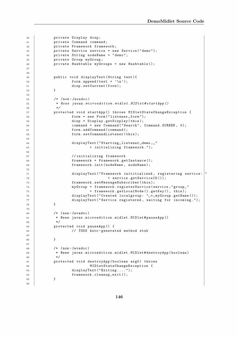
DemoMidlet Source Code
40 private Display disp;
41 private Command command;
42 private Framework framework;
43 private Service service = new Service("demo");
44 private String nodeName = "demo";
45 private Group myGroup;
46 private Hashtable myGroups = new Hashtable ();
47
48
49 public void displayText(String text){
50 form.append(text + ’\n’);
51 disp.setCurrent(form);
52 }
53
54 /* (non -Javadoc)
55 * @see javax.microedition.midlet.MIDlet#startApp ()
56 */
57 protected void startApp () throws MIDletStateChangeException {
58 form = new Form("listener form");
59 disp = Display.getDisplay(this);
60 command = new Command("Search", Command.SCREEN , 0);
61 form.addCommand(command );
62 form.setCommandListener(this);
63
64 displayText("Starting listener demo , "
65 + initializing framework.");
66
67 // initializing framework
68 framework = Framework.getInstance ();
69 framework.init(nodeName , nodeName );
70
71 displayText("Framework inititialized , registering service: "
72 + service.getServiceID ());
73 framework.setMessageSubscriber(this);
74 myGroup = framework.registerService(service ,"group_"
75 + framework.getLocalNode (). getKey(), this);
76 displayText("Created localgroup: " + myGroup.getName ());
77 displayText("Service registered , waiting for incoming.");
78 }
79
80 /* (non -Javadoc)
81 * @see javax.microedition.midlet.MIDlet#pauseApp ()
82 */
83 protected void pauseApp () {
84 // TODO Auto -generated method stub
85
86 }
87
88 /* (non -Javadoc)
89 * @see javax.microedition.midlet.MIDlet#destroyApp(boolean)
90 */
91 protected void destroyApp(boolean arg0) throws
92 MIDletStateChangeException {
93 displayText("Exiting ....");
94 framework.cleanup_exit ();
95 }
96
146
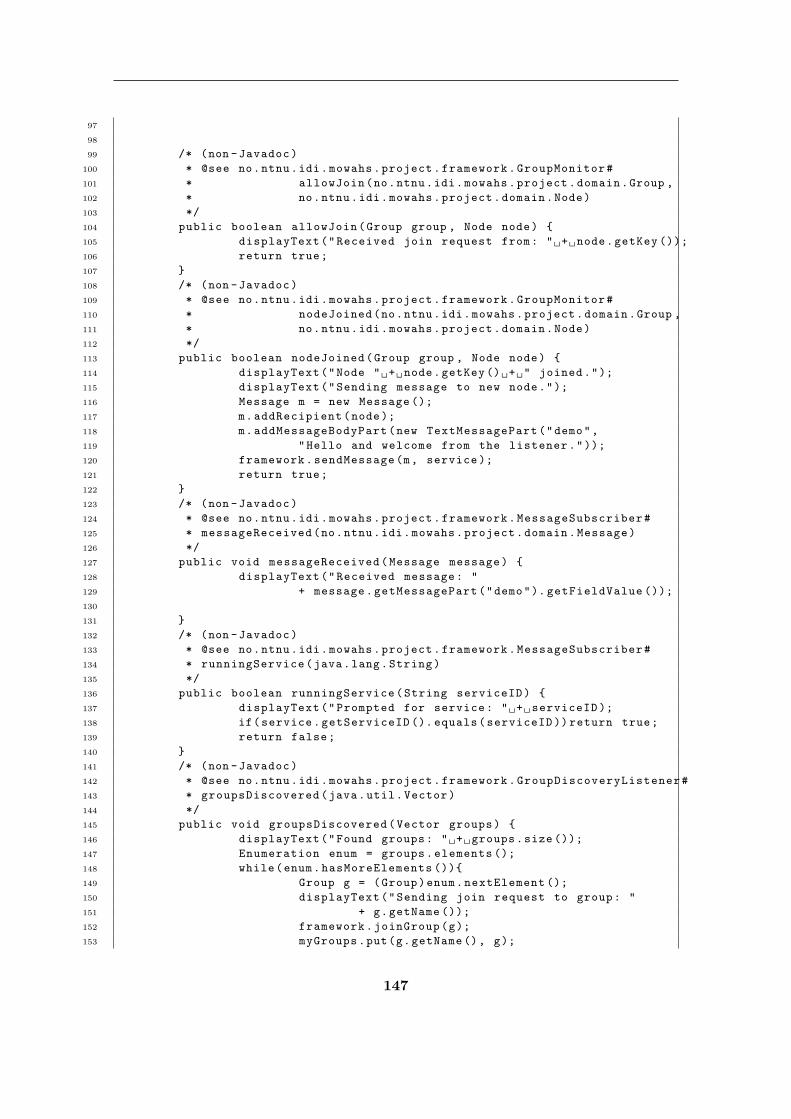
97
98
99 /* (non -Javadoc)
100 * @see no.ntnu.idi.mowahs.project.framework.GroupMonitor#
101 * allowJoin(no.ntnu.idi.mowahs.project.domain.Group ,
102 * no.ntnu.idi.mowahs.project.domain.Node)
103 */
104 public boolean allowJoin(Group group , Node node) {
105 displayText("Received join request from: " + node.getKey ());
106 return true;
107 }
108 /* (non -Javadoc)
109 * @see no.ntnu.idi.mowahs.project.framework.GroupMonitor#
110 * nodeJoined(no.ntnu.idi.mowahs.project.domain.Group ,
111 * no.ntnu.idi.mowahs.project.domain.Node)
112 */
113 public boolean nodeJoined(Group group , Node node) {
114 displayText("Node " + node.getKey () + " joined.");
115 displayText("Sending message to new node.");
116 Message m = new Message ();
117 m.addRecipient(node);
118 m.addMessageBodyPart(new TextMessagePart("demo",
119 "Hello and welcome from the listener."));
120 framework.sendMessage(m, service );
121 return true;
122 }
123 /* (non -Javadoc)
124 * @see no.ntnu.idi.mowahs.project.framework.MessageSubscriber#
125 * messageReceived(no.ntnu.idi.mowahs.project.domain.Message)
126 */
127 public void messageReceived(Message message) {
128 displayText("Received message: "
129 + message.getMessagePart("demo"). getFieldValue ());
130
131 }
132 /* (non -Javadoc)
133 * @see no.ntnu.idi.mowahs.project.framework.MessageSubscriber#
134 * runningService(java.lang.String)
135 */
136 public boolean runningService(String serviceID) {
137 displayText("Prompted for service: " + serviceID );
138 if(service.getServiceID (). equals(serviceID )) return true;
139 return false;
140 }
141 /* (non -Javadoc)
142 * @see no.ntnu.idi.mowahs.project.framework.GroupDiscoveryListener#
143 * groupsDiscovered(java.util.Vector)
144 */
145 public void groupsDiscovered(Vector groups) {
146 displayText("Found groups: " + groups.size ());
147 Enumeration enum = groups.elements ();
148 while(enum.hasMoreElements ()){
149 Group g = (Group)enum.nextElement ();
150 displayText("Sending join request to group: "
151 + g.getName ());
152 framework.joinGroup(g);
153 myGroups.put(g.getName(), g);
147
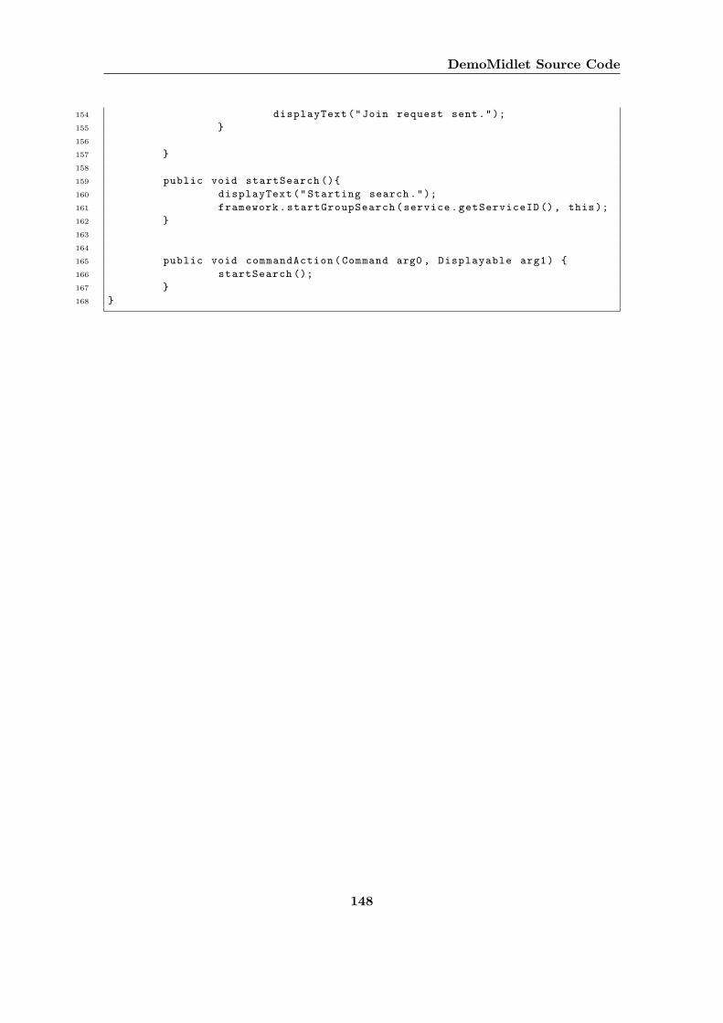
DemoMidlet Source Code
154 displayText("Join request sent.");
155 }
156
157 }
158
159 public void startSearch (){
160 displayText("Starting search.");
161 framework.startGroupSearch(service.getServiceID (), this);
162 }
163
164
165 public void commandAction(Command arg0 , Displayable arg1) {
166 startSearch ();
167 }
168 }
148
Bibliography
[1] Mobile ad-hoc netze. http://www-i4.informatik.rwth-aachen.de/~mesut/manet/display.html, 2002. (Accessed: 15.09.2004).
[2] The anhinga project website. http://www.cs.rit.edu/~anhinga/, 2004. (Accessed:20.09.2004).
[3] Getting started with bluetooth. http://developers.sun.com/techtopics/mobility/midp/articles/bluetooth1/, 2004. (Accessed: 25.08.2004).
[4] The jadabs project website. http://www.iks.inf.ethz.ch/projects/Jadabs, 2004.(Accessed: 29.08.2004).
[5] The jxta for j2me project (proxyless) website. http://jxme.jxta.org/, 2004. (Ac-cessed: 08.09.2004).
[6] Project jxta community. http://www.jxta.org, 2004. (Accessed: 05.09.2004).
[7] The wi-fi alliance homepage. http://www.wi-fi.org/OpenSection/index.asp,2004. (Accessed: 02.09.2004).
[8] T. . T. Association. Protocol Adaption Layer (PAL) for IEEE 1394 over IEEE802.15.3, 2004.
[9] N. Borisov, I. Goldberg, and D. Wagner. Security of the wep algorithm. Technicalreport, Computer Science Division,University of Berkeley,California, 2001.
[10] M. Boulkenafed, D. Sacchetti, and V. Issarny. Using group management to tamemobile ad hoc networks. In E. Lawrence, B. Pernici, and J. Krogstie, editors, MobileInformation Systems, pages 245–261. Springer, 2004.
[11] S. S. Bygdas, Øystein Myhre, S. Nyhus, T. Urnes, and Asmund Weltzien. Bubbles:Navigating content in mobile ad-hoc networks. Technical report, Telenor FOU, 2003.
[12] M. Conti. Body, personal, and local ad hoc wireless networks. Technical report,Consiglio Nazionale delle Ricerche, 2003.
[13] M. Conti. Peer-to-peer research at stanford. Technical report, Computer ScienceDepartment, 2003.
[14] CR80News. Ntru announces aerolink, first complete security system for wirelessconsumer electronics and commercial appliances. 2003.
149
BIBLIOGRAPHY
[15] G. Cugola and G. P. Picco. Peerware: Core middleware support for peer-to-peerand mobile systems. Technical report, Dipartimento di Elettronica e Informazione,Politecnico di Milano, Italy, 2003.
[16] C. A. Ellis, S. J. Gibbs, and G. Rein. Groupware: some issues and experiences.Commun. ACM, 34(1):39–58, 1991.
[17] M. Esbjornsson and M. Ostergren. Hocman: Supporting mobile group collaboration.Technical report, Mobility, Interactive Institute, Stockholm, Sweden, 2002.
[18] G. H. Forman and J. Zahorjan. The challenges of mobile computing. Technical report,1994.
[19] B. Garbinato and P. Rupp. From ad hoc networks to ad hoc applications. Technicalreport, Institut d’Informatique et Organisation, Universite de Lausanne, Switzerland,2003.
[20] L. Gong. Project jxta: A technology overview. Technical report, Sun Microsystems,2002.
[21] A. Heinemann, J. Kangasharju, F. Lyardet, and M. Muhlhauser. iclouds – peer-to-peer information sharing in mobile environments. In H. Kosch, L. Boszormenyi, andH. Hellwagner, editors, Euro-Par 2003. Parallel Processing, 9th International Euro-Par Conference, volume 2790 of Lecture Notes in Computer Science, pages 1038–1045,Klagenfurt, Austria, 2003. Springer.
[22] L. Holmquist, J. Falk, and J. Wigstrm. Supporting group collaboration with inter-personal awareness devices, 1999.
[23] B. Hopkins and R. Antony. Bluetooth for java. 2003.
[24] IEEE. IEEE Standard for Information technology telecommunications and informa-tion exchange between system - Local and metropolitan area networks Specific Re-quirements Part 15.3: Wireless Medium Access Control (MAC) and Physical Layer(PHY) Specifications for High Rate Personal Area Networks (WPANs), 2003.
[25] IEEE. IEEE Standard for Information technology telecommunications and informa-tion exchange between system - Local and metropolitan area networks Specific Re-quirements Part 15.4: Wireless Medium Access Control (MAC) and Physical Layer(PHY) Specifications for Low-Rate Personal Area Networks (LR-WPANs), 2003.
[26] Intel. White Paper: Wireless USB - The First High-speed Personal Wireless Inter-connect, 2004.
[27] R. E. Johnson and B. Foote. Designing reusable classes. Journal of Object-OrientedProgramming, 1(2):22–35, 1988.
[28] T. Karygiannis and L. Owens. Wireless network security. Technical report, NationalInstitute of Standards and Technology, U.S. Department of Commerce, 2002.
150
BIBLIOGRAPHY
[29] L. Kirkhus and A. R. Sveen. An examination of mobile devices for spontaneouscollaboration. Technical report, Institutt for datateknikk og informasjonsvitenskap,2003.
[30] L. Kirkhus and A. R. Sveen. Mowahs - mobile collaboration framework. Technicalreport, Institutt for datateknikk og informasjonsvitenskap, 2004.
[31] C. W. Klaus. Wireless lan security faq. Technical report, Internet Security Systems(ISS), 2002.
[32] J. Knudsen. Getting started with jxta for j2me. Technical report, Sun Microsystems,2002.
[33] R. Kolic. Wireless usb brings greater convenience and mobility to devices. http://deviceforge.com/articles/AT9015145687.html, 2004. (Accessed: 20.09.2004).
[34] G. Kortuem. Proem: A peer-to-peer computing platform for mobile ad hoc networks.Technical report, Wearable Computing Laboratory, Department of Computer Science,2001.
[35] G. Kortuem. A methodology and software platform for building wearable communi-ties. Technical report, University of Oregon, 2002.
[36] G. Kortuem, J. Schneider, D. Preuitt, T. G. C. Thompson, S. Fickas, and Z. Segall.When peer-to-peer comes face-to-face, collaborative peer-to-peer computing in mobielad hoc networks. Technical report, 2001.
[37] M. M. Labs. Thinking tags. Technical report, MIT Media Labs, 1998.
[38] B. Laurie and A. Laurie. Serious flaws in bluetooth security lead to disclosure ofpersonal data. Technical report, A.L. Digital Ltd, 2003.
[39] P. J. Magnus Frodigh and P. Larsson. Wireless ad hoc networking - the art of net-working without a network. Technical report, Ericsson, 2000.
[40] D. S. Milojicic, V. Kalogeraki, R. Lukose, K. Nagaraja, J. Pruyne, B. Richard,S. Rollins, and Z. Xu. Peer-to-peer computing. Technical report, Hewlett-PackardCompany,HP Laboratories Palo Alto, 2002.
[41] P. og Teletilsynet. Det norske telemarkedet 1. halvar 2004.
[42] J. S. Olson, S. Teasley, L. Covi, and G. Olson. The (currently) unique advantages ofcollocated work. chapter 5, pages 113–135. MIT Press, 2002.
[43] N. Sastry and D. Wagner. Security considerations for IEEE 802.15.4 networks. InACM Workshop on Wireless Security (WiSe 2004), October 2004.
[44] D. Schoder and K. Fischbach. Peer-to-peer, anwendungsbereiche und herausforderun-gen, in: Schoder detlef; fischbach, kai; teichmann, rene: Peer-to- peer (p2p),okonomische, technologische und juristische perspektiven. Technical report, 2002.
151
BIBLIOGRAPHY
[45] T. Schwotzer and K. Geihs. Proxy lady: Mobile support for opportunistic communi-cation. Technical report, Mobile Informatics Group, Viktoria Institute, Gothenburg,Sweden, 1999.
[46] T. Schwotzer and K. Geihs. Shark - a system for management, synchronization andexchange of knowledge in mobile user groups. Technical report, Intelligent Networksand Management of Distributed Systems, TU Berlin, Germany, 2002.
[47] T. B. S. I. G. (SIG). Bluetooth enhanced data rate: Draft v1.0 test specifications.https://www.bluetooth.org/spec/, 2004. (Accessed: 01.09.2004).
[48] T. B. S. I. G. (SIG). Bluetooth r© wireless technology shipments hit two million aweek. http://www.bluetooth.com/, 2004. (Accessed: 29.08.2004).
[49] M. Stonebraker, P. M. Aoki, W. Litwin, A. Pfeffer, A. Sah, J. Sidell, C. Staelin,and A. Yu. Mariposa a wide-area distributed database system. Technical report,Department of Electrical Engineering and Computer Sciences, 1996.
[50] A. Sutcliffe. Scenario-based requirements analysis. Requirements Engineering,3(1):48–65, 1998.
[51] M. Thoresen. Peer-to-peer systems. Technical report, Institutt for datateknikk oginformasjonsvitenskap, 2003.
[52] M. Treskbeck. Security of bluetooth: An overview of bluetooth security. http://www.cs.hut.fi/Opinnot/Tik-86.174/Bluetooth_Security.pdf, 2000. (Accessed:10.09.2004).
[53] H. V. Vliet. Software Engineering. 2000.
[54] M. Wiberg and Ake Grønlund. Exploring mobile cscw: Five areas of questions forfurther research.
[55] B. J. Wilson. JXTA, second edition. 2002.
[56] Asa Rudstrom, M. Svensson, R. Coster, and K. Hook. Mobitip: Using bluetooth as amediator of social context. Technical report, Swedish Institute of Computer Science,2004.
152