a low-level active vision framework for collaborative...
TRANSCRIPT

A Low-level Active Vision Framework for
Collaborative Unmanned Aircraft Systems
Martin Danelljan, Fahad Shahbaz Khan, Michael Felsberg, Karl Granstrom,Fredrik Heintz, Piotr Rudol, Mariusz Wzorek, Jonas Kvarnstrom,
Patrick Doherty
Linkoping University
Abstract. Micro unmanned aerial vehicles are becoming increasinglyinteresting for aiding and collaborating with human agents in myriads ofapplications, but in particular they are useful for monitoring inaccessibleor dangerous areas. In order to interact with and monitor humans, thesesystems need robust and real-time computer vision subsystems that allowto detect and follow persons.In this work, we propose a low-level active vision framework to ac-complish these challenging tasks. Based on the LinkQuad platform, wepresent a system study that implements the detection and tracking ofpeople under fully autonomous flight conditions, keeping the vehiclewithin a certain distance of a person. The framework integrates state-of-the-art methods from visual detection and tracking, Bayesian filtering,and AI-based control. The results from our experiments clearly suggestthat the proposed framework performs real-time detection and trackingof persons in complex scenarios.
Keywords: Visual Tracking, Visual Surveillance, Micro UAV, ActiveVision
1 Introduction
Micro unmanned aerial vehicles (micro UAVs) are becoming popular for aidingin numerous applications such as search and rescue, inspection, early warning,forest-fire reconnaissance and remote localization of hazardous radio-active ma-terials. Generally these platforms have been remotely piloted with no activeautonomous vision capabilities. However, in recent years significant amount ofresearch has been done to develop active vision based functionalities for suchplatforms. The purpose of a vision component is to interpret the rich visualinformation captured by onboard cameras. In this paper, we propose a robustactive vision framework for collaborative unmanned aircraft systems.
Several active vision frameworks for micro UAVs have been reported in recentyears [20, 24, 18]. A vision based method for path planning of micro UAVs usinga three-dimensional model of the surrounding environment is proposed in [20].Yu et al. [24] propose a 3D vision system for estimating the UAV height overground, used in the control loop of the helicopter. The work of [18] proposes a

2 Danelljan et al.
hardware and software system for micro UAVs that is capable of autonomousflight using onboard processing for computer vision. In this work, we tacklethe challenging problem of developing an active vision framework for robustdetection and tracking of persons in complex environments, which is necessaryfor stable virtual leashing, i.e. following a person at a predetermined distance.
Generally most approaches to object detection are based on the learning-from-examples paradigm [19, 4, 7]. In recent years, discriminative, part-basedmethods [25, 7] have been shown to provide excellent performance for persondetection. These methods rely on intensity information for image representa-tion [15, 4] and latent support vector machines for classification. A sliding win-dow technique is then employed to scan an image at multiple scales. Contrary tothe intensity based methods, Khan et al. [12] propose to use color informationwithin the part-based framework of Felzenszwalb et al. [7]. The method employscolor attributes for color representation while providing excellent detection per-formance on benchmark datasets. In our framework, we have the option to selectboth intensity and color based detection models for person detection.
Tracking of visual objects in an image sequence is a challenging computervision problem. Typically methods employ either generative or discriminativeapproaches to tackle the visual tracking problem. The generative methods [1,13, 14] work by searching for regions that are most similar to the target model.A template or subspace based model is usually employed. The discriminative ap-proaches [8, 26, 10] work by di↵erentiating the target from the background usingmachine learning techniques. Recently, Danelljan et al. [5] proposed an adap-tive color attributes based tracking approach that outperforms state-of-the-arttracking methods while operating at real-time. In our framework, we incorporatethis tracking approach due to its robustness and computational e�ciency.
Multiple object tracking (mot) is the processing of multiple detections frommultiple objects such that reliable estimates of the number of objects, as well aseach object’s state, can be obtained. The phd filter is a computationally feasiblefirst order approximation of the Bayesian multiple object tracking filter [16, 17],and its output is a joint Bayesian estimate of the number of objects and theirrespective states. In comparison to classic mot filters such as Joint ProbabilisticData Association Filter (jpdaf) or Multi-Hypothesis Tracker (mht), see e.g. [2],the phd filter does not require a solution to the data assocation problem. In ourframework, we use a PHD filter to improve the tracking results obtained by theadaptive color based attributes based tracking.
In this work we propose a low-level active vision framework for unmannedaircraft systems based on the LinkQuad platform. Our framework employs state-of-the-art object detection, object tracking, Bayesian filtering and AI-based con-trol approaches. Our experimental results clearly demonstrate that the proposedframework e�ciently detects and tracks persons in both indoor and outdoor com-plex scenarios. Our framework can thus be used for stable virtual leashing.
The rest of the paper is organized as follows. Section 2 describes the used Mi-cro UAV platform. Section 3 presents our active vision framework. Experimentalresults are provided in section 4. Finally, conclusions are provided in section 5.

A Low-level Active Vision Framework for Unmanned Aircraft Systems 3
Fig. 1: LinkQuad platform with the color camera sensor module.
2 Active Vision Platform
The micro UAV platform used for the system evaluation is a LinkQuad, see fig-ure 1. It is a highly versatile autonomous UAV. The platform’s airframe is char-acterized by a modular design which allows for easy reconfiguration to adopt toa variety of applications. Thanks to a compact design (below 70 centimeters tip-to-tip) the platform is suitable for both indoor and outdoor use. It is equippedwith custom designed optimized propellers which contribute to an enduranceof up to 30 minutes. Depending on the required flight time, one or two 2.7 Ahbatteries can be placed inside an easily swappable battery module. The maxi-mum take-o↵ weight of the LinkQuad is 1.4 kilograms with up to 300 grams ofpayload.
The LinkQuad is equipped with in-house designed flight control board - theLinkBoard. The LinkBoard has a modular design that allows for adjusting theavailabl computational power depending on mission requirements. Due to theavailable onboard computational power, it has been used for computationallydemanding applications such as the implementation of an autonomous indoorvision-based navigation system with all computation performed on-board. In thefull configuration, the LinkBoard weighs 30 grams, has very low power consump-tion and has a footprint smaller than a credit card. The system is based on twoARM-Cortex microcontrollers running at 72 MHz which implement the coreflight functionalities and optionally, two Gumstix Overo boards for user soft-ware modules. The LinkBoard includes a three-axis accelerometer, three rategyroscopes, and absolute and di↵erential pressure sensors for estimation of thealtitude and the air speed, respectively. The LinkBoard features a number of in-terfaces which allow for easy extension and integration of additional equipment.It supports various external modules such as a laser range finder, analogue anddigital cameras on a gimbal, a GPS receiver, and a magnetometer.
4 Danelljan et al.
Visual Object Detector
Visual Object Tracker
Target Distance Estimator
Leashing Control
Fusion
UAV state
UAV API
Images WiFi
Target in image coordinates
Distance and heading to target
Flight targets UAV state P2P modem
Camera Capture
Video
LinkQuad / LinkBoard
UAV Control
Flight target state
Target Filter
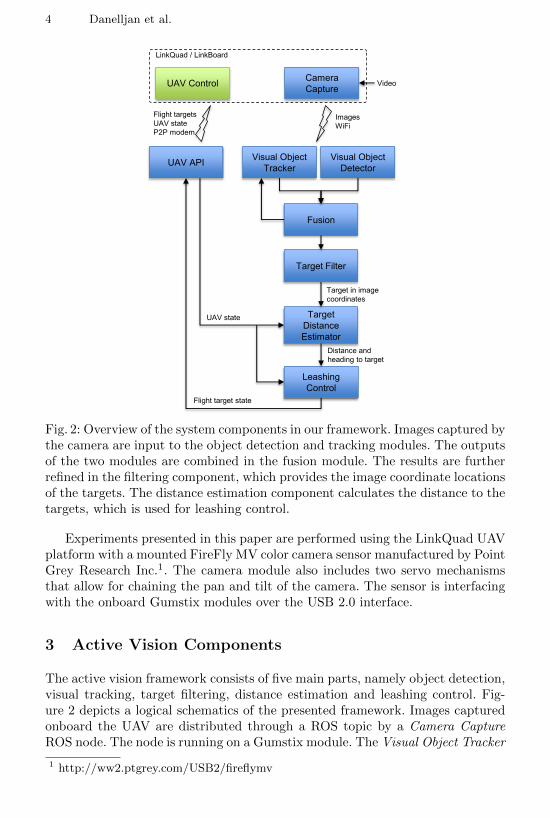
Fig. 2: Overview of the system components in our framework. Images captured bythe camera are input to the object detection and tracking modules. The outputsof the two modules are combined in the fusion module. The results are furtherrefined in the filtering component, which provides the image coordinate locationsof the targets. The distance estimation component calculates the distance to thetargets, which is used for leashing control.
Experiments presented in this paper are performed using the LinkQuad UAVplatform with a mounted FireFly MV color camera sensor manufactured by PointGrey Research Inc.1. The camera module also includes two servo mechanismsthat allow for chaining the pan and tilt of the camera. The sensor is interfacingwith the onboard Gumstix modules over the USB 2.0 interface.
3 Active Vision Components
The active vision framework consists of five main parts, namely object detection,visual tracking, target filtering, distance estimation and leashing control. Fig-ure 2 depicts a logical schematics of the presented framework. Images capturedonboard the UAV are distributed through a ROS topic by a Camera CaptureROS node. The node is running on a Gumstix module. The Visual Object Tracker
1 http://ww2.ptgrey.com/USB2/fireflymv

A Low-level Active Vision Framework for Unmanned Aircraft Systems 5
and Visual Object Detector use this image stream as input. The object detec-tor generates person detections in the images, while the visual tracker estimatesthe locations of visual object hypotheses in image coordinates. The results fromthese two components are fused at a later stage in the framework. In the targetfiltering component, the visual object estimates are further refined by modelingkinematics and detector noise. This component stabilizes the object identitiesand counters false detections. Image location estimates generated by the filteringcomponent are then used to compute the distance and heading to the targets.This information is input to the leashing control module, which provides flightdestinations to the UAV Control system.
3.1 Visual Object Detection
We implement two object detection methods, namely the HOG and Color-HOGbased detectors. The former is the standard approach proposed by Dalal andTrigs [4]. It works by computing a feature representation using histogram oforiented gradients (HOG) on positive and negative samples of persons from thetraining set. A Support Vector Machine (SVM) classifier is then trained on thesesamples. Given a test image, the learned model is applied in a sliding windowfashion to find potential detection responses. Our framework employs the HOGbased classifier implemented in OpenCV.
As a second option, we use the Color-HOG detector proposed by Khan etal. [12]. The detector augments the standard HOG based method with colorinformation. A late fusion scheme is employed to combine the color and shapeinformation. We use color attributes [22] as an explicit color representation andfuse it with HOG features.
The visual object detector is implemented as a ROS node and runs in aseparate thread. When the detections from a camera image are computed, theresult is published. The detector then starts to process the latest available imagefrom the camera.
3.2 Visual Object Tracking
We use the Adaptive Color Tracker (ACT) proposed recently by Danelljan et al.[5]. It has shown to achieve state-of-the-art performance on a large number ofbenchmark videos. The method is simple and computationally e�cient, makingit especially suitable for robotic applications. Here we use the ACT to trackhumans, but the method is generic and can be applied to track any visual object.
The ACT works by learning a discriminative classifier on the target appear-ance. Its low computational cost is primarily due to two properties possessed bythis tracking method. First, it assumes a periodic extension of the local imagepatch, which allows the usage of the fast Fourier transform (FFT) for the heavycomputations. Second, the tracker applies a dynamically adaptive dimensional-ity reduction technique to reduce the number of features while preserving theimportant characteristics of the target appearance.

6 Danelljan et al.
To update the tracker model at some frame n, a template tn
of size M ⇥Ncentred around the target is first extracted. Danelljan et al. [5] suggests using apixel dense representation of color name features [22] augmented with the usualgrayscale values. These features are preprocessed by a normalization procedurefollowed by a windowing operation. The resulting template t
n
is used to computethe kernelized auto-correlation a
n
(x, y) for all cyclic shifts x and y (in pixels)along the first and second coordinate respectively.
an
(x, y) = (⌧x,y
Pn
tn
, Pn
tn
) (1)
Here, is a Gaussian radial basis function kernel and ⌧x,y
is the cyclic shiftoperator. The projection operator P
n
, that is computed by the dimensionalityreduction technique, maps the pixel features onto a low-dimensional linear sub-space. The desired output score y
n
(i.e. the classifier labels) is set to a M ⇥Nsampled Gaussian function with a centred peak. The numerator ↵
n
and denom-inator �
n
of the Fourier transformed classifier coe�cients are updated with thenew sample template using:
↵n
= (1� �)↵n�1 + �y
n
an
(2a)
�n
= (1� �)�n�1 + �a
n
(an
+ �) (2b)
Here, � denotes a scalar learning rate parameter and � is a scalar regularizationparameter. The multiplication between signals is point-wise and f denotes thediscrete Fourier transform (DFT) of a signal f . The tracker model also includesa template appearance u
n
, which is updated as:
un
= (1� �)un�1 + �t
n
. (3)
The tracking model is applied to a new image at time step n to locate theobject by first extracting a M ⇥ N sample template v
n
. This is done at thepredicted target location and the extraction procedure is the same as for t
n
.The kernelized cross-correlation between the sample template and the learnedtemplate appearance is given by:
bn
(x, y) = (⌧x,y
Pn�1vn, Pn�1un
) (4)
The confidence scores sn
over the patch vn
are then computed as a convolutionin the Fourier domain.
sn
= F�1
(↵n�1bn
�n�1
)(5)
Here F�1 denotes the inverse DFT operator. Henriques et al. [10] showed thatthe kernelized correlations a
n
and bn
can be computed e�ciently using the FFT.The feature projection operator P
n
is represented by a matrix that projectsthe feature vector of each pixel in a template onto a linear subspace. This pro-jection matrix is obtained through an adaptive Principal Component Analysisproposed by [5]. A symmetric matrix L
n
= (1 � ⌘)Kn�1 + ⌘C
n
is computed as
A Low-level Active Vision Framework for Unmanned Aircraft Systems 7
a linear combination between the feature covariance matrix Cn
of the currenttemplate appearance u
n
and a symmetric matrix Kn
. Here, ⌘ is a scalar learn-ing rate parameter. The matrix Q
n
depends on the previously chosen projectionmatrices and is updated as K
n
= (1�⌘)Kn�1+⌘PT
n
Dn
Pn
in each frame, whereD
n
is a diagonal weight matrix. This term ensures smoothness, which preventsthe classifier coe�cients to become outdated. The new projection matrix P
n
isobtained by performing an eigenvalue decomposition on the matrix L
n
and se-lecting the eigenvectors corresponding to the largest eigenvalues. This schemefor calculating the projection matrix minimizes a loss function formulated in [5],which regards both the current appearance and the set of previously selectedfeature spaces.
The visual tracking is implemented as a separate node in ROS in our frame-work. It processes all targets sequentially. All parameters of the ACT are set assuggested by the authors.
3.3 Combining Tracking and Detection
We use a separate component to fuse the tracking and detector results. It isimplemented as a separate ROS node, and thus runs in a separate thread. Whennew tracking results are available for a visual object, the location and appearancemodel for this object is simply replaced with the ones returned by the tracker.
Person detections received by the detector component is used for the followingpuropses: to initialize new object candidates, verify existing object candidates,identify tracking failures and to correct the location and size of the visual ob-ject. A new object candidate is initialized when a detection is received that isnot overlapping with any current objects or candidates. The image region thatcorresponds to this object candidate is then tracked until it is either verifiedor discarded. A candidate is verified if additional overlapping detections are re-ceived during the next-coming frames. If this occurs, the candidate is upgradedto a known object, otherwise it is discarded and removed.
To identify tracking failures, each known object must be verified with anoverlapping detection within a certain number of frames. The object is identifiedas a tracking failure if no overlapping detection is received within the specifiednumber of frames since the last verification. This leads to the removal of thatobject. To counter tracker drift, we also correct the target location and size witha partially overlapping detection if the overlap is less than a threshold.
3.4 Target Filtering
The target tracking module has three main parts: Bayesian estimation of
1. kinematics: velocity vectors are estimated for each target;2. state uncertainty: full covariance matrices are estimated for each target state;3. target ID: the visual tracking IDs are stabilized using the information con-
tained in the estimated state vectors and covariance matrices.

8 Danelljan et al.
The visual tracking output at time step k is a set Zk
= {z(j)k
}Nz,k
j=1 , where each
element z(j)k
= (I(j)k
, d(j)k
) consist of an id I(j)k
2 N a detection window d(j)k
2 R4
that defines the position in the image and the windows width and height.The purpose of the multiple object tracking (mot) filter is to use the sets Z
k
to estimate the object set Xk
= {⇠(i)k
}Nx,k
i=1 , where both the number of objects
Nx,k
and the object states ⇠(i)k
are unknown. The object state at time step k is
defined as ⇠(i)k
= (x(i)k
, J(i)k
), where J(i)k
is the object’s id and x(i)k
is the objectstate vector,
xk
=⇥pxk
, pyk
, vxk
, vyk
, wk
, hk
⇤T(6)
where [pxk
, pyk
] is the position, [vxk
, vyk
] is the velocity, and wk
and hk
is the widthand height of the detection window.
The process and detection models are
xk+1 =F
k+1xk
+wk+1 =
2
4I2 T
s
I2 02
02 I2 02
02 02 I2
3
5xk
+wk+1 (7)
zk
=Hk
xk
+ ek
=⇥I2 02 02
⇤xk
+ ek
, (8)
where wk+1 and e
k
are zero-mean Gaussian noice processes with covariancematrices Q
k+1 and Rk
, respectively.The visual tracking output is used as input in a Probability Hypothesis Den-
sity (phd) filter [16, 17]. Specifically we use a Gaussian mixture implementation[21] with a uniform distribution for the position component of the birth phd
intensity [3].
3.5 Distance Estimation
Controlling the UAV by leashing requires a distance estimate to the target. Thisis obtained by assuming a horizontal ground plane and a fixed person height h.Figure 3 contains a simple illustration of the scenario. The angle ' between theoptical axis and the projection ray of the top of the target is calculated as
' = arctan
✓y
f
◆(9)
where y is the normalized image top-coordinate of the bounding box and f isthe e↵ective focal length. Using the known altitude z and camera pitch angle ⇢,the distance d can be obtained from simple trigonometry.
d =z � h
tan(⇢� ')(10)
Since we have a camera with a narrow field of view, a small yaw angle of the cam-era relative the target can be assumed. We therefore approximate the e↵ectivefocal length to f = 1 m. We also assume that the UAV is flying approximatelyupright when extracting the top coordinate of the target. However, these assump-tions have minimal impact due to other dominant model errors and measurementinaccuracies.

A Low-level Active Vision Framework for Unmanned Aircraft Systems 9
Optical axisImage plane
Camera center
y
z
h
d
d
z-h
-
f
Fig. 3: To estimate the ground distance d between the UAV and the person, weassume a horizontal ground plane and a person height h. The angle ' is obtainedfrom normalized image coordinate y of the upper edge of the bounding box andthe e↵ective focal length f . The UAV altitude z and camera pitch ⇢ are known.The distance is obtained using simple geometry by considering the larger trianglein the figure.
3.6 Leashing Control Module
The task of the Leashing Control module is to keep specified distance betweenthe UAV and the target, and point the UAV towards the target. To achieve itthe Leashing Control outputs the flight target state vector i.e. [vx
t
, vyt
, vzt
, t
],where [vx
t
, vyt
, vzt
] are the target velocities, and t
is the target heading.
The target state vector is used by the UAV velocity controller which in turncalculates target angle values used by the attitude stabilisation inner controlloops. Flight target velocities i.e. [vx
t
, vyt
, vzt
] are calculated in the following way.First, a new flight target position is calculated on a line which includes thecurrent UAV position and the target position at a specified distance from thetarget. Then, the target velocities are proportional to the di↵erence between thecurrent UAV position and the new flight target’s position.
Flight target heading t
is calculated based on the UAV and target positionsin the world coordinate frame.
Additionally the Leashing Control module implements a strategy for findinga target. This is done by commanding a sweeping motion using the headingtarget in order to increase chances of reacquiring a lost target or finding one incase it has not yet been found.

10 Danelljan et al.
CT TLD EDFT Struck LSHT ACT
basketball 171 65.2 108 159 156 9.29
bolt 371 88 355 391 122 4.2
boy 32.1 4.09 2.34 3.35 32.6 4.39couple 77.8 64.3 89.4 12.7 114 123david 14.3 34.3 9.2 43.2 14.8 7.73
david3 68.5 136 6.46 107 53.7 9.11human 428 110 5.77 5.36 6.59 7.25singer1 15 10.6 16.6 12.4 21 9.21
skating1 184 104 199 82.3 82.3 7.95
trellis 51.1 55.9 59.6 15.3 61.2 20.8walking 214 110 5.77 5.36 6.59 7.25walking2 64.6 63.1 28.7 12.9 50.6 47.7
Average CLE 141 70.5 73.8 70.8 60.1 21.5
(a) Center location error.
CT TLD EDFT Struck LSHT ACT
basketball 4.14 51.3 30.5 11.6 5.1 99.9
bolt 2.57 32 2.57 2.86 37.4 100
boy 66.6 100 100 100 56.3 99.8couple 30.7 31.4 21.4 83.6 10.7 10.7david 79.2 65.8 100 32.7 76 100
david3 43.3 35.3 100 33.7 75 90.5human 0.485 42.2 100 100 100 100
singer1 86.9 100 49.3 98.3 40.2 95.7skating1 8.5 27 16.3 51 56 100
trellis 20.9 44.5 47.6 73.5 44.8 68.9walking 12.1 42.2 100 100 100 100
walking2 40 37.6 40.2 85.6 39.8 42.4
Average DP 33 50.8 59 64.4 53.4 84
Average FPS 62 31.6 19 11.2 11.3 106
(b) Distance precision.
Table 1: The results of the visual tracking evaluation. Six methods are comparedon 12 benchmark sequences using center location error (a) and distance precision(b). The average frame-rate is also included in table (b). The best and secondbest results are shown in red and blue respectively.
4 Experimental Evaluation
In this section we provide our experimental results. First, we evaluate the em-ployed visual tracking method on benchmark videos and compare it to otherstate-of-the-art real-time visual tracking methods. Second, we show the impactof the target filtering component in our framework. Finally, we provide somefight test results.
4.1 Visual Tracking
We compare the ACT [5] with five other recent tracking methods from theliterature with real-time performance, namely CT [26], TLD [11], EDFT [6],Struck [8] and LSHT [9]. We use the code and the suggested parameter settingsprovided by the respective authors. The recent evaluation protocol provided byWu et al. [23] is used.2 From their dataset of 50 videos, we select the 12 videos ofhuman or face tracking, where the setting is most similar to our application. Theperformance is measured in center location error (CLE) and distance precision(DP). CLE is defined as the average distance between the centroids of the trackedand ground truth bounding boxes, over the sequence. Distance precision is therelative number of frames in a sequence for which the distance between thecentroids is less than 20 pixels. We also compare the frame rates of the di↵erentapproaches. The experiments were performed on an Intel Xenon 2 core 2.66 GHzCPU with 16 GB RAM.
The results are shown in table 1. ACT and Struck perform best on the samelargest number of videos (five for CLE and six for DP). However, ACT obtains
2 The evaluation code and benchmark image sequences are available athttps://sites.google.com/site/trackerbenchmark/benchmarks/v10
A Low-level Active Vision Framework for Unmanned Aircraft Systems 11
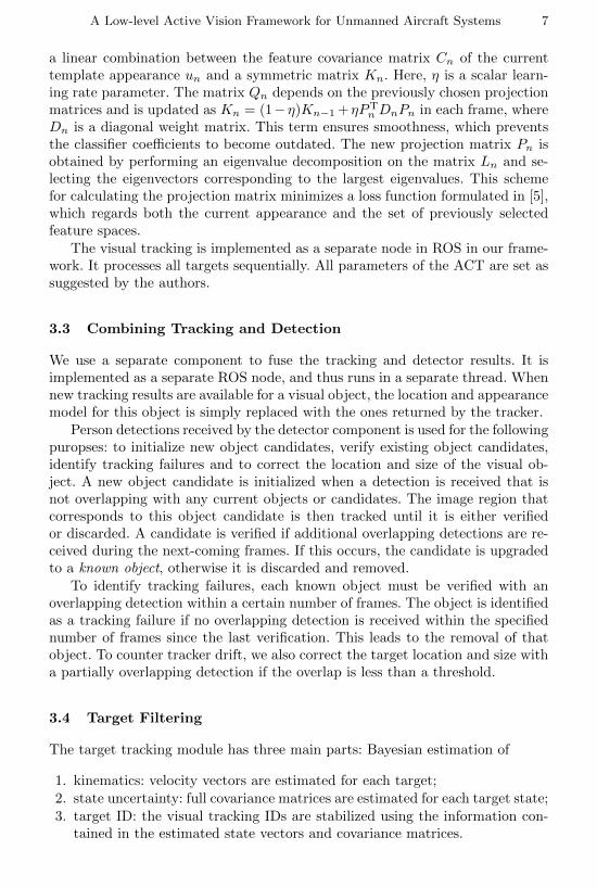
Fig. 4: Example multiple object tracking results with two targets: one headingleft and one heading right in the image. Shown are bounding boxes with IDs:visual tracking is indicated by red, multiple object tracking is indicated by green.During the crossing the targets overlap significantly, however the multiple targettracking maintains correct target IDs despite the visual tracking is associatingerroneous IDs.
significantly better average performance, where it improves 23.6% in averagedistance precision over Struck. Moreover, the ACT is the fastest tracker in ourevaluation, with almost ten times higher frame rate than Struck.
4.2 Target Filtering
The benefits of the target tracking module are most apparent in terms of sta-bilizing the tracking IDs. In ambiguous situations, such as when two or moretargets pass each other in the image, the visual tracking IDs may become mixedup. Here the target tracking module uses the additional information containedin the kinematics and uncertainty estimates to maintain the target IDs correctly.
An example with two targets is given in Fig. 4. In the top left the two targetsare approaching each other, with visual tracking/target IDs 14/2 (to the left,heading right) and 10/1 (to the right, heading left). During the crossing, shownin top right, the two targets overlap significantly. After the crossing, shownbottom left, both Visual tracker 14 and Visual tracker 10 have stuck to the

12 Danelljan et al.
target heading right in the image, and for the target heading left in the image anew Visual tracker with ID 15 has been initialized. However, the target trackingmodule has correctly fused the Visual tracking information with the estimatedkinematics and uncertainty information, and the target IDs are correct. Shortlythereafter, shown bottom right, the Visual tracking has correctly deleted Visualtracker with ID 14.
4.3 System Evaluation
The presented system has been evaluated in a number of autonomous flightsduring which a micro UAV was following a person. A short description of aplatform used for the flight tests is presented. Below follows a description of theexperimental setup and the results of the flight tests.
Experimental setup The presented system has been evaluated in a numberof autonomous flights performed in a lab equipped with a motion capture sys-tem manufactured by Vicon Motion Systems company3. The system capturespositions in a volume of 11 ⇥ 11 ⇥ 5 meters and it was used both to provide areference for the vision system performance evaluation and the state of the UAVused for the control (i.e. position and velocity in x, y, and z axes and heading).The state used for control was sent wirelessly and with an update rate of 10 Hz.
Figure 2 presents the interconnections and placement of the system compo-nents during the experimental flights.
Flight test results During several flight tests the performance of the wholesystem was evaluated in terms of the accuracy of the vision-based distance esti-mation and the tracking performance of the control system.
Figure 5a presents the distance between the target and the UAV platformduring a flight. The distance to keep was set to 5.5 meters and is depicted withthe green line. The blue dotted curve shows the distance estimated based onvision as described in section 3. The red curve is the distance calculated usingthe Vicon reference system. As can be seen, during the flight the distance waskept with maximum error of 1.6 meters from the estimate and 1.9 meters fromthe reference.
Figure 5b presents the target heading t
as described in section 3.6 along withthe actual heading during the leashing experiment. In case of slow changes in thetarget heading, our framework accurately tracks the target. For faster changes,the heading error increases due to the limited maximum allowed heading rate ofthe UAV. It is worthy to mention that it has little impact on the overall leashingperformance.
In summary, our framework is able to perform the leashing control task usingthe active vision component described earlier. The accuracy of the distance esti-mation can be improved further by taking into account the size of the detection
3 http://www.vicon.com/

A Low-level Active Vision Framework for Unmanned Aircraft Systems 13
20 40 60 80 100 120 1403.5
4
4.5
5
5.5
6
6.5
7
7.5
8
Time [s]
Dis
tanc
e [m
]
ReferenceEstimateTarget
(a) Distance estimation.
20 40 60 80 100 120 140−140
−120
−100
−80
−60
−40
−20
0
20
40
60
Time [s]
Hea
ding
[deg
]
TargetActual
(b) Heading control.
Fig. 5: The estimated relative distance of the target relative to UAV (a), targetand actual heading (b) during the leashing experiment.
box. However, our results suggest that for the leashing task the simple distanceestimation approach provides consistent results on several indoor scenarios. Formost leashing applications, a small bias in the distance estimate is tolerablesince the purpose of our framework is to follow a person at a roughly constantdistance.
5 Conclusion
In this paper, we present a low-level active vision framework for unmanned air-craft systems. Our framework is implemented on the LinkQuad platform andemploys state-of-the-art object detection, object tracking, Bayesian filtering andAI-based methods. It e�ciently detects and tracks persons in real-time which isused for virtual leashing. Future work involves recognizing human actions suchas hand waiving, clapping etc. for advanced virtual leashing scenarios. Anotherpotential research direction is to integrate e�cient person re-identification tech-niques to encounter heavy occlusions and out-of-view scenarios.
References
1. Bao, C., Wu, Y., Ling, H., Ji, H.: Real time robust l1 tracker using acceleratedproximal gradient approach. In: CVPR (2012)
2. Bar-Shalom, Y., Willett, P.K., Tian, X.: Tracking and data fusion, a handbook ofalgorithms. YBS (2011)
3. Beard, M., Vo, B., Vo, B.N., Arulampalam, S.: A partially uniform targetbirth model for Gaussian mixture PHD/CPHD filtering. IEEE Transactions onAerospace and Electronic Systems 49(4), 2835–2844 (Oct 2013)
4. Dalal, N., Triggs, B.: Histograms of oriented gradients for human detection. In:CVPR (2005)
14 Danelljan et al.
5. Danelljan, M., Shahbaz Khan, F., Felsberg, M., van de Weijer, J.: Adaptive colorattributes for real-time visual tracking. In: Proceedings of IEEE Conference onComputer Vision and Pattern Recognition (CVPR) (2014)
6. Felsberg, M.: Enhanced distribution field tracking using channel representations.In: ICCV Workshop (2013)
7. Felzenszwalb, P.F., Girshick, R.B., McAllester, D.A., Ramanan, D.: Object de-tection with discriminatively trained part-based models. PAMI 32(9), 1627–1645(2010)
8. Hare, S., Sa↵ari, A., Torr, P.: Struck: Structured output tracking with kernels. In:ICCV (2011)
9. He, S., Yang, Q., Lau, R., Wang, J., Yang, M.H.: Visual tracking via localitysensitive histograms. In: CVPR (2013)
10. Henriques, J., Caseiro, R., Martins, P., Batista, J.: Exploiting the circulant struc-ture of tracking-by-detection with kernels. In: ECCV (2012)
11. Kalal, Z., Matas, J., Mikolajczyk, K.: P-n learning: Bootstrapping binary classifiersby structural constraints. In: CVPR (2010)
12. Khan, F.S., Anwer, R.M., van de Weijer, J., Bagdanov, A., Vanrell, M., Lopez, A.:Color attributes for object detection. In: CVPR (2012)
13. Kwon, J., Lee, K.M.: Tracking by sampling trackers. In: ICCV (2011)14. Liu, B., Huang, J., Yang, L., Kulikowski, C.: Robust tracking using local sparse
appearance model and k-selection. In: CVPR (2011)15. Lowe, D.G.: Distinctive image features from scale-invariant points. IJCV 60(2),
91–110 (2004)16. Mahler, R.: Multitarget Bayes filtering via first-order multi target moments. IEEE
Transactions on Aerospace and Electronic Systems 39(4), 1152–1178 (Oct 2003)17. Mahler, R.: Statistical Multisource-Multitarget Information Fusion. Artech House,
Norwood, MA, USA (2007)18. Meier, L., Tanskanen, P., Fraundorfer, F., Pollefeys, M.: Pixhawk: A system for
autonomous flight using onboard computer vision. In: ICRA (2011)19. van de Sande, K., Uijlings, J.R.R., Gevers, T., Smeulders, A.W.M.: Segmentation
as selective search for object recognition. In: ICCV (2011)20. Sinopoli, B., Micheli, M., Donato, G., Koo, T.J.: Vision based navigation for an
unmanned aerial vehicle. In: ICRA (2001)21. Vo, B.N., Ma, W.K.: The Gaussian mixture probability hypothesis density filter.
IEEE Transactions on Signal Processing 54(11), 4091–4104 (Nov 2006)22. van de Weijer, J., Schmid, C., Verbeek, J.J., Larlus, D.: Learning color names for
real-world applications. TIP 18(7), 1512–1524 (2009)23. Wu, Y., Lim, J., Yang, M.H.: Online object tracking: A benchmark. In: CVPR
(2013)24. Yu, Z., Nonami, K., Shin, J., Celestino, D.: 3d vision based landing control of
a small scale autonomous helicopter. International Journal of Advanced RoboticSystems 4(1), 51–56 (2007)
25. Zhang, J., Huang, K., Yu, Y., Tan, T.: Boosted local structured hog-lbp for objectlocalization. In: CVPR (2010)
26. Zhang, K., Zhang, L., Yang, M.: Real-time compressive tracking. In: ECCV (2012)