a framework for fine robotic assembly - arxiv · a framework for fine robotic assembly ... or the...
TRANSCRIPT
A Framework for Fine Robotic Assembly
Francisco Suarez-Ruiz and Quang-Cuong Pham
Abstract— Fine robotic assembly, in which the parts to beassembled are small and fragile and lie in an unstructuredenvironment, is still out of reach of today’s industrial robots.The main difficulties arise in the precise localization of theparts in an unstructured environment and the control of contactinteractions. Our contribution in this paper is twofold. First,we propose a taxonomy of the manipulation primitives thatare specifically involved in fine assembly. Such a taxonomy iscrucial for designing a scalable robotic system (both hardwareand software) given the complexity of real-world assemblytasks. Second, we present a hardware and software architecturewhere we have addressed, in an integrated way, a number ofissues arising in fine assembly, such as workspace optimization,external wrench compensation, position-based force control, etc.Finally, we show the above taxonomy and architecture in actionon a highly dexterous task – bimanual pin insertion – which isone of the key steps in our long term project, the autonomousassembly of an IKEA chair.
I. INTRODUCTION
Robotics has largely contributed to increasing industrialproductivity and to helping factory workers on tedious,monotonous tasks, such as pick and place, welding, orpainting. There are however some major challenges that stillprevent the automation of many repetitive tasks – especiallyin ‘light’ industries – such as the assembly of small parts inthe electronics, shoes or food industries.
As opposed to ‘heavy’ industries, where sophisticatedassembly lines provide a highly structured environment (forinstance, on car assembly lines, the position of the car frameis known to sub-millimeter precision), ‘light’ industries areassociated with unstructured environments, where the smallparts to be assembled are placed in diverse positions andorientations. While tremendous progress has been made in3D perception in recent years, current 3D-vision systems arestill not precise enough for fine assembly.
Another related problem is that most robots currentlyused in the industry are position-controlled, that is, theycan achieve very precise control in position and velocity,at the expense of poor, or no, control in force and torque.Yet, force or compliant control is crucial while assemblingfragile, soft, small parts. Assembly tasks imply by essencecontacts between the robot and the environment, making thesensing and control of contact forces decisive. A number ofcompliant robots have been developed in recent years, suchas the KUKA Lightweight Robot [1] or the Barrett WholeArm Manipulator (WAM) [2], but, compared to existingindustrial robots, they are still one order of magnitude
F. Suarez-Ruiz and Q.-C. Pham are with the School of Mechanical andAerospace Engineering, NTU, Singapore.
This work was supported by Tier 1 grant RG109/14 awarded by theMinistry of Education of Singapore.
more expensive, less robust and more difficult to maintain.We believe therefore that the key to automatizing ‘light’industries lies in augmenting existing industrial position-controlled manipulators with extra functionalities, such ascompliant control, through the addition of affordable hard-ware components (e.g. end-effector force/torque sensor) andsmart planning, sensing and control software.
The goal of this paper is to present our frameworkdedicated to fine assembly – our long term project beingto demonstrate the capability of that framework by au-tonomously assembling an IKEA chair.
Previous works have attempted to complete similar tasks[3], [4], [5]. Specifically, Knepper et al. [4] present a multi-robot system that assembles an IKEA table. They focus moreon the task planning architecture than in the challenges offine assembly. To cope with the force interactions they needa dedicated tool based on a compliant gripper for screwingthe table legs. In order to use off-the-shelf components, weprefer software over mechanical compliance.
In this paper, we discuss two initial contributions. First, wepropose a taxonomy of the manipulation primitives involvedin fine assembly. Such a taxonomy serves as crucial guidelinefor designing a scalable robotic manipulation system (bothhardware and software), given the complexity of real-worldassembly tasks. In particular, thinking in terms of primitivesmoves beyond the low-level representations of the robot’smovements (classically joint-space or task-space) and en-ables generalizing robot capabilities in terms of elementalactions that can be grouped together to complete any task.
As our taxonomy is tailored for industrial fine assembly, itdiffers from existing manipulation taxonomies [6], [7], [8],[9] in two key aspects: (i) we focus on parallel-jaw grippers(the most common and robust gripper in the industry), whichexcludes some complex primitives such as in-hand manipu-lation; (ii) in addition to the interaction of the gripper withthe gripped object, we also consider multi-object interactions(e.g. the gripped object interacts with another object), whichconstitute the essence of assembly.
Our second contribution is the development of a hardwareand software framework based on the above taxonomy andtailored for robotic assembly. The hardware comprises anoptical motion capture system and two industrial position-controlled manipulators, each equipped with a force/torque(F/T) sensor at the wrist and a parallel gripper. The twomanipulators are necessary since most assembly tasks requiretwo hands to complete (see [10] for a complete survey onbimanual manipulation). Compared to integrated bimanualrobots, such as the Toyota Dual Arm Robot [11], theYaskawa Motoman SDA10D [12], or the ABB dual arm
arX
iv:1
509.
0480
6v1
[cs
.RO
] 1
6 Se
p 20
15

YuMI [13], our two independent manipulators enable higherworkload and larger workspace, at a fraction of the cost.
On the software side, we address a number of issuesarising in fine assembly, such as workspace optimization,external wrench compensation, position-based force control,etc. These issues have often been discussed in the literature,but we address them here in an integrated way and on a singlesoftware platform built on top of the Robot Operating System(ROS) [14]. We intend to make this platform available asopen-source in the near future.
To illustrate the above developments, we consider a highlydexterous task: bimanual pin insertion. This task requiresmost of the capabilities just mentioned, such as bimanualmotion planning, object localization, control of contact in-teractions, etc. It also constitutes one of the key steps inour long term project, the autonomous assembly of an IKEAchair. Finally, it yields a fully quantifiable way to measure thedexterous performance of a robotic manipulation system andis therefore a good test for the generalizability and simplicityof implementation.
The paper is structured as follows. In Section II, theproposed manipulation taxonomy is presented. The manipu-lation primitives have been selected for assembly tasks,but can also be used for the description of any type ofrobotic tasks. Section III gives details regarding our hardwareand software framework and describes the requirements thatwe have identified as essential to perform all the motionprimitives. Section IV depicts the bimanual pin insertiontask, showing how it can be broken down into differentsubtasks, which in turn can be divided into manipulationprimitives. Finally, Section V draws some conclusions andsketches some directions for future research.
II. MANIPULATION PRIMITIVES FOR ASSEMBLY
We present a motion-centric taxonomy that classifies ma-nipulation primitives required for assembly tasks. Typically,two different approaches have been used in previous taxo-nomies: object- [6], [7] or motion-centric [8], [9]. Object-centric classifications define the primitives focusing on thecharacteristics of the manipulated object, which compli-cates their extension to different type of systems. On theother hand, motion-centric typologies allow to use differentstrategies to complete the same task. This flexible approachcan be adapted to diverse manipulation systems dependingon their capabilities. Our taxonomy focuses on industrialmanipulators equipped with a parallel-jaw gripper. In thecase of more complex end-effectors, in-hand manipulationprimitives can be used [8].
A. Definitions
• Task. High-level work to be done by the robotic ma-nipulation system, e.g. bimanual insertion of a pin intoa wood stick.
• Subtask. Functional division of a task, e.g. grasping apin, picking a stick, or inserting a pin. A task normallyinclude several subtasks.
• Manipulation Primitive. Basic action defined in thetaxonomy. Typically, various primitives constitute a sub-task. Moreover, they comprise the basic capabilities thatthe software framework provides for each manipulator.
• Prehensile. The hand/gripper can stabilize the objectwithout need for external forces such as gravity. Ba-sically, the object is grasped.
• Contact. The hand/gripper or the object being graspedis touching any external body.
• Motion. The end-effector is moving with respect to therobot’s coordinate frame.
• Push/Pull. A force is applied and the object beingmanipulated is moving as a result.
B. Manipulation Taxonomy
Taxonomies classify information into descriptive groups.In robotics, taxonomies are usually used to define the possi-ble grasps of dexterous robotic hands [6], [7]. These kindof taxonomies focus mainly on in-hand movements anddisregard the larger movements of a robotic manipulator.
Similarly to [8] and [9], a motion-centric approach hasbeen adopted for the taxonomy proposed in this work. Itallows for greater flexibility than an object-centric approach,which would restrict the manipulation to the a priori knowl-edge of the object. The motion-centric approach is suitablefor any manipulation performed by a hand-type manipulator.Fig. 1 shows the motion-centric taxonomy proposed in thiswork. It is independent to the object being manipulated. Forthe classification of bimanual manipulation tasks, the primi-tives can describe the actions performed by each manipulator.
C. Primitives Requirements
Once the manipulation primitives have been defined, it isneeded to determine their specific requirements. As shown inFig. 1, there are three natural levels of difficulty dependingon the number of objects involved in the manipulation. Fora position-controlled manipulator, contact interactions repre-sent an additional challenge, which prompts us to indicate thecontrol mode required for each primitive in the taxonomy.
1) Position Mode: This control mode is used for all theprimitives that do not involve contact interactions. Despiteof being inherently simple for a position-controlled manipu-lator, this mode requires precise localization of the objectswhen the robot moves in their proximity. For instance, ifthe robot needs to grasp and object, first it will approach tothe grasp position (primitive 2 ), but errors in the positionestimation may result on the robot hitting the object andfailing the task.
2) Compliant Mode: This mode is used for primitiveswhere there are contact interactions between the gripper andthe object or between the gripped object and another ob-ject. Depending on the task, force- or impedance-controlledmotion will be used. One example of a force-controlledprimitive is number 5 . It can be used to maintaincontact with a table while the gripper is closed to grasp asmall object. In this case, controlling the force guaranteesthe contact between the gripper and the table and avoids

Manipulation Primitive
Non-Prehensile
No Contact
No Motion
1
Motion
Approach
2
Retreat
3
FollowPath
4
Contact
No Motion
5
Motion
Push
6
Pull
7
FollowPath
8
Prehensile
No Contact
No Motion
9
Motion
Approach
10
Retreat
11
FollowPath
12
Contact
No Motion
13
Motion
Push
14
Pull
15
FollowPath
16
2 Objects
1 Object
No Object
Interaction
Fig. 1. Manipulation taxonomy proposed in this work. Any robotic manipulation task can be classified using these primitives. There are three levels ofdifficulty depending on the number of objects the robot is interacting with. The control mode is indicated by the shape enclosing the primitive number. Arectangle indicates position-control mode. An ellipse indicates compliant-control mode.
unwanted interaction forces. An example of an impedance-controlled primitive is number 15 . Imagine a task where theforce required to extract an object is unknown, therefore theforce-controlled approach may fail. Moreover, this compliantmode can be used to reduce the uncertainty in the localizationof the objects. For instance, the robot can detect the exactposition of the object once it detects a contact.
III. HARDWARE AND SOFTWARE PLATFORM
The robotic platform used in this work is characterizedby cost-efficient, off-the-shelf components combined withclassical position-control industrial manipulators. This willhelp address the problems of fine assembly under unstruc-tured environments at a limited cost.
The main components of the proposed platform are:
• 2 × Denso VS060: Six-axis industrial manipulator.
• 2 × Robotiq Gripper 2-Finger 85: Parallel adaptivegripper designed for industrial applications. Closureposition, velocity and force can be controlled. Thegripper opening goes from 0 to 85 mm. The grip forceranges from 30 to 100 N.
• 2 × ATI Gamma Force-Torque (F/T) Sensor: It mea-sures all six components of force and torque. Theyare calibrated with the following sensing ranges: f =[32, 32, 100] N and τ = [2.5, 2.5, 2.5] Nm.
• 1 × Optitrack Motion Capture System: Six Prime 17Wcameras that can track up to five rigid bodies. The errorin position and orientation estimation is directly relatedto the amount of markers used per rigid body (minimumthree markers are required). We have observed that theestimation error ranges between ±0.5 − 3 mm for theposition and ±0.01 − 0.05 radians for the orientation.This estimation error is due to the diameter of the

z0
x0
y0
d1
q11
q12
d2
q13
d3 q14
q15
d4
q16
z16
x16
y16
d
z1
x1
y1
q21
q22
q23
q24
q25
q26
z26
x26
y26
Fig. 2. Kinematic diagram of the bimanual setup. The distance d has beenoptimized to maximize the joint and intersection workspaces.
markers which ranges between 3 to 10 mm in our setup.
A. Bimanual Workspace Optimization
Appropriate values for the distance between the two robots(d in Fig. 2) can be selected either by trial and error or bysolving an optimization problem with constraints imposed asa function of the resulting reachable workspace. The typicalapproach to quantify the manipulability of serial robots is touse a quality value for reachable positions along the robot’sworkspace. Normally the Yoshikawa’s manipulability index[15] is used:
w =
√det(JJT
)(1)
This value describes the distance to singular configurationsbut it does not consider the robot’s joint limits. A modifiedindex can be penalize to account for the effects of the jointlimits on the manipulability of a serial manipulator.
P (q) =
n∑j=1
(l+j − l−j
)24(l+j − qj
) (qj − l−j
) , (2)
We use the penalization function (2) proposed in [16],which results in the modified index w∗ = w
P (q) .Finally, we maximize a linear combination between the
union and the intersection workspace that is a function of thedistance d. The resulting workspace of the bimanual setup isshown in Fig. 2 where the optimized distance is d = 1.042meters.
B. Motion Planning in Free Space
For all the collision-free movements the Bi-directionalRapidly-Exploring Random Trees (RRTs) algorithm [17]
Fig. 3. Normalized reachability of the bimanual setup. The workspaceintersection shows the combined reachability of the two manipulators.
available in OpenRAVE [18] is used. Similarly to LaVallein [19], our system uses prioritized planning. The motionpath is calculated for one robot at the time and is repeateduntil all the movements are completed. This reduces theoverload in collision checking and avoids the need for pathcoordination between robots.
C. External Wrenches Estimation
In our setup, one F/T sensor is mounted at the wrist ofeach robot. It measures the dynamic effects of the end-effector and any external wrench due to contact interactionswith the environment. External wrenches can be estimatedby compensating the dynamic effects of the end-effector(weight and inertia) [20], [21], [22]. This approach requiresthe identification of the inertial parameter of the end-effector.We propose an off-line approach which only uses the F/Tsensor measurements along a defined trajectory.
1) Optimal Excitation Trajectories: During the identifi-cation process, it is necessary to ensure that the excitationis sufficient to provide accurate and fast parameter estima-tion in the presence of disturbances, and that the collecteddata is simple and yields reliable results. First, a trajectoryparametrization is selected, and second the trajectory pa-rameters are calculated by means of optimization.
The excitation trajectory for each joint has been chosen asa finite sum of harmonic sine and cosine functions, similar to[20], [21]. Each one with a total of 2N+1 parameters, whichcorrespond to the degrees of freedom of the optimizationproblem.
qj (t) =
N∑k=1
akjwfk
sin (wfkt)−bkjwfk
cos (wfkt) + q0j (3)
qj (t) =
N∑k=1
akj cos (wfkt) + bkj sin (wfkt) (4)
qj (t) =
N∑k=1
−akjwfk sin (wfkt) + bkjwfk cos (wfkt) . (5)
0 2 4 6 8 10Time [s]
−1.0
−0.5
0.0
0.5
1.0Po
sitio
n[ra
d]
Joint 1Joint 2Joint 3Joint 4Joint 5Joint 6
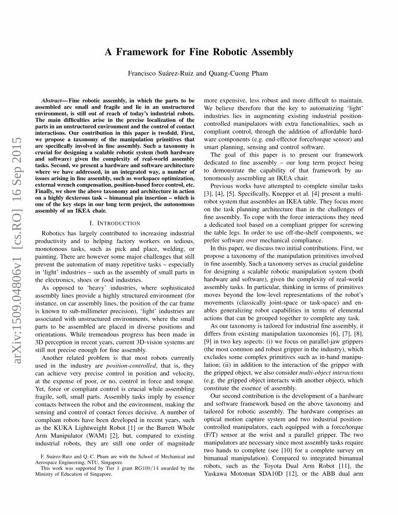
Fig. 4. Optimized robot-excitation trajectory. One period of the optimizedjoint trajectories is shown. These trajectories consist of a five-term Fourierseries with a base frequency of 0.1 Hz. The trajectory parameters areoptimized according to the d-optimality criterion, taking into accountworkspace limitations, and constraints on joint velocities and accelerations.
The coefficients akj and bkj are the amplitudes of the sine andcosine functions. q0j is the offset of the position trajectory.
Fig. 4 shows the optimized trajectory for the six robot’sjoints (11 parameters per joint). The base frequency has beenselected in order to cover a larger part of the robot workspacefor the given maximum joint velocities and accelerations,even thought it requires a longer measurement time. Theidentification process is performed off-line for each end-effector.
2) End-effector Dynamics: The wrist-mounted F/T sensoris measuring the loads on the last link excluding itself. Inparticular, since the end-effector is always present, it is pos-sible to compensate the wrench it generates by determiningits inertial parameters. The Newton-Euler equation of thislast body refereed to the F/T sensor frame Os is,
fs = Isas + vs × Isvs , (6)
where the resulting spatial force fs is a function ofthe spatial inertia Is, the spatial acceleration as, and thespatial velocity vs. As shown in [22], the force and torquemeasurements by the wrist sensor must be expressed in termsof the product of known values and the unknown inertialparameters. The measured wrench fs can be written as:
fs =
[as S (ωs) + S (ωs)S (ωs) 00 −S (as) L (ωs) + S (ωs)L (ωs)
] ms
csl (Is)
(7)
where L (ωs) is a 3 × 6 matrix of angular velocityelements, l (Is) is the inertia matrix vectorized and S (ωs)is the skew-symmetric matrix. (7) can be expressed morecompactly as,
fs = Asφs , (8)
where As is a 6× 10 matrix, and φs is the vector of the10 unknown inertial parameters. To estimate the force/torque
kp
du
dtkv
+ + ROBOT
Environment
F/T Sensor
+fr fe xf
xr
xc
-
fs
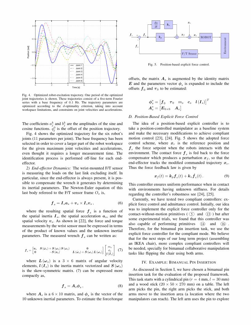
Fig. 5. Position-based explicit force control.
offsets, the matrix As is augmented by the identity matrixE and the parameters vector φs is expanded to include theoffsets f0 and τ 0 to be estimated:
φ∗s =
[f0 τ 0 ms cs l (Is)
]TA∗
s =[E6×6 As
]D. Position-Based Explicit Force Control
The idea of a position-based explicit controller is totake a position-controlled manipulator as a baseline systemand make the necessary modifications to achieve compliantmotion control [23], [24]. Fig. 5 shows the adopted forcecontrol scheme, where xr is the reference position andfr the force setpoint when the robots interacts with theenvironment. The contact force fs is fed back to the forcecompensator which produces a perturbation xf , so that theend-effector tracks the modified commanded trajectory xc.Thus the force feedback law is given by
xf (t) = kpfe(t) + kvfe(t) . (9)
This controller ensures uniform performance when in contactwith environments having unknown stiffness. For detailsregarding the controller’s robustness see [24], [25].
Currently, we have tested two compliant controllers: ex-plicit force control and admittance control. Initially, our ideawas to implement the explicit force controller only for thecontact-without-motion primitives ( 5 and 13 ) but aftersome experimental trials, we found that this controller wasalso capable of performing primitives 14 and 16 .Therefore, for the bimanual pin insertion task, we use theexplicit force controller for the compliant mode. We believethat for the next steps of our long term project (assemblingan IKEA chair), more complex compliant controllers willbe needed, specially for bimanual collaborative manipulationtasks like flipping the chair using both arms.
IV. EXAMPLE: BIMANUAL PIN INSERTION
As discussed in Section I, we have chosen a bimanual pininsertion task for the evaluation of the proposed framework.This task starts with a cylindrical pin (r = 4 mm, l = 30 mm)and a wood stick (20 × 50 × 270 mm) on a table. The leftarm picks the pin, the right arm picks the stick, and botharms move to the insertion area (a location where the twomanipulators can reach). The left arm uses the pin to explore

TABLE IPARAMETERS OF THE PEG-IN-HOLE TASK USED FOR THE ASSESSMENT
OF THE BIMANUAL MANIPULATION SYSTEM.
Parameter Symbol Value
Hole diameter dH 8.1 mmPeg diameter dP 8 mmPeg height h 30 mm
the stick and to find the hole. Once it finds the hole, insertsand releases the pin.
The task is naturally divided into three mid-level sub-tasks:• Compliant grasp of the pin,• Pick & place the stick, and• Compliant insertion of the pin
A. Compliant Grasping
Moving the left arm to grasp directly the pin is not possibledue to two uncertainties in the system: First, the positionerror in the perception system can be up to ±3 mm. Second,the difference in the height of the gripper between the openedand the closed position is 13.9 mm. These two factors alongwith the mechanical compliance of the gripper at the tip(intended for encompassing grip) require extra capabilitiesto grasp small objects from the table top.
To cope with this, we use a compliant grasping approach.Initially, the robot moves to a pregrasp position, just abovethe pin, then it moves down until it detects contact withthe table. The position-based explicit force controller is thenused to maintain the contact with the table within a safevalue that does not overcome the compliance of the gripper’stip. Finally the gripper is closed while the force controllermaintains the contact with the table.
B. Pick & Place
This is a simpler sub-task. The right arm picks the stickand ‘place’ it in the insertion area. It needs to be hold tightlyso that the left arm can perform the exploration, find the holeand insert the pin.
C. Compliant Pin Insertion
The insertion sub-task is of the peg-in-hole type. This kindof setup is generally characterized using a precision valuedefined as,
I = log 2
(dH
dH − dP
), (10)
where dH is the diameter of the hole and dP is the diameterof the peg. Table I shows the parameters for our pin insertionsetup, which has a precision value I = 6.34 bits. Otherstudies have used precision values within the same order ofmagnitude [26], [27] in telemanipulation applications wherethe operator deals with the challenge of localizing preciselythe hole.
Due to the uncertainties on the position of the objects(pin and stick), the exact position of the holes is unknown.Moreover, given the parameters of the peg-in-hole setup(Table I), we have observed that the insertion fails for
TABLE IIMANIPULATION PRIMITIVES USED FOR THE BIMANUAL PIN INSERTION
TASK. THE TIME TO TASK COMPLETION IS 83 SECONDS.
Time [s] Primitive ActionStart End
Compliant Grasping (left arm, 13 seconds.)0 9 2 Approach to the pregrasp position9 10 5 Contact with the table10 11 5 Close gripper maintaining contact11 12 9 Grasp the pin12 13 11 Pick-up the pin from the tablePick & Place (right arm, 18 seconds.)13 22 2 Approach to the grasp position22 24 9 Grasp the stick24 31 11 Move the stick to the insertion areaCompliant Pin Insertion (left arm, 52 seconds.)31 40 10 Move the pin above the stick40 43 14 Contact between the pin and stick43 56 16 Detect first edge of the stick56 59 11 Move above and contact the stick59 70 16 Detect second edge of the stick70 73 11 Move above and contact the stick73 80 16 Find the hole80 82 14 Insert the pin82 83 3 Release the pin
position errors above 0.5 mm. To cope with these problems,we perform a force-controlled exploration of the wood stickusing the pin. The left arm moves above the stick with the pingrasped, then starts moving down until contact is detected.Next, we look for two edges of the stick. Considering thatits dimensions are known, after finding the edges, the middleaxis of the holes can be calculated. The robot ‘scratches’the pin over the stick following that axis until it finds thehole. After that, a force-controlled motion is carried outf = [0, 0,−fz] to insert the pin. This value ensures that thepin will move only in the −z direction until it reaches thebottom of the hole or the gripper touches the stick. From (9),it can be seen that the pin is driven down the distance xf untilthe force error fe equals to zero. This motion emulates andspring-damper impedance that depends on the compensatorgains kp and kv . Finally the left arm releases the pin andmoves back to its home position.
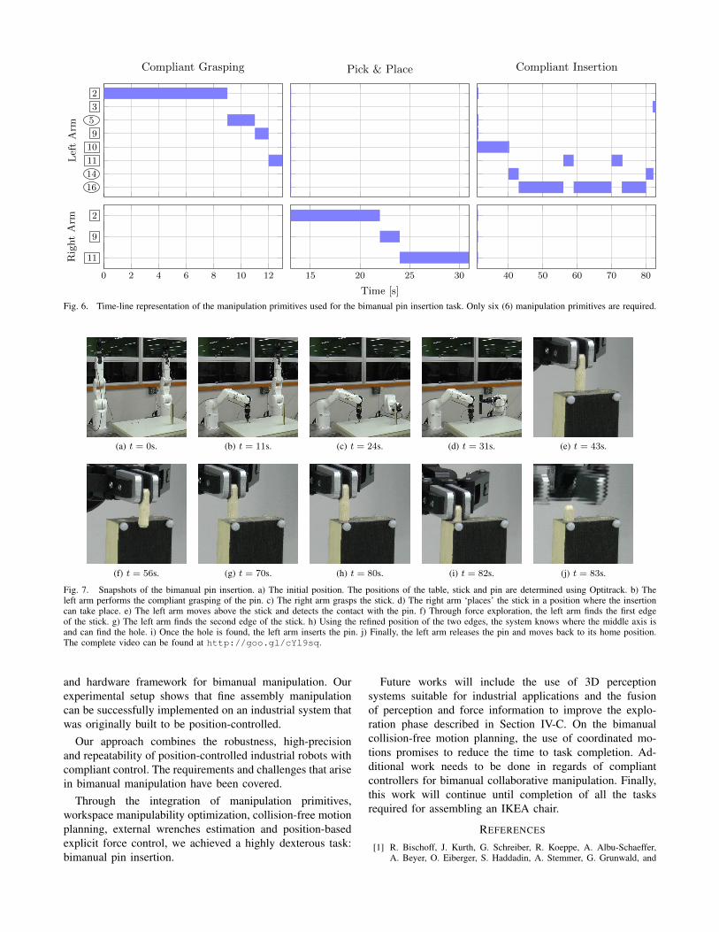
Table II depicts the manipulation primitives required foreach sub-task with their corresponding times. The time totask completion for the bimanual pin insertion is 83 seconds.Fig. 6 depicts the transitions between manipulation primitivesin a time-line representation. Fig. 7 shows snapshots of thebimanual pin insertion where each sub-task can be visuallyidentify. The complete video can be found at http://goo.gl/cYl9sq.
V. CONCLUSIONS AND FUTURE WORK
This paper introduced a complete framework for fineassembly tasks using industrial robots. We have presenteda new taxonomy of manipulation primitives tailored forindustrial fine assembly. This taxonomy focuses on parallel-jaw grippers and interactions with single or multiple objectswhich are the essence of assembly tasks. Moreover, we havediscussed the development and implementation of a software
16
14
11
10
9
5
3
2
LeftArm
Compliant Grasping Pick & Place Compliant Insertion
0 2 4 6 8 10 12
11
9
2
RightArm
15 20 25 30
Time [s]
40 50 60 70 80
Fig. 6. Time-line representation of the manipulation primitives used for the bimanual pin insertion task. Only six (6) manipulation primitives are required.
(a) t = 0s. (b) t = 11s. (c) t = 24s. (d) t = 31s. (e) t = 43s.
(f) t = 56s. (g) t = 70s. (h) t = 80s. (i) t = 82s. (j) t = 83s.
Fig. 7. Snapshots of the bimanual pin insertion. a) The initial position. The positions of the table, stick and pin are determined using Optitrack. b) Theleft arm performs the compliant grasping of the pin. c) The right arm grasps the stick. d) The right arm ‘places’ the stick in a position where the insertioncan take place. e) The left arm moves above the stick and detects the contact with the pin. f) Through force exploration, the left arm finds the first edgeof the stick. g) The left arm finds the second edge of the stick. h) Using the refined position of the two edges, the system knows where the middle axis isand can find the hole. i) Once the hole is found, the left arm inserts the pin. j) Finally, the left arm releases the pin and moves back to its home position.The complete video can be found at http://goo.gl/cYl9sq.
and hardware framework for bimanual manipulation. Ourexperimental setup shows that fine assembly manipulationcan be successfully implemented on an industrial system thatwas originally built to be position-controlled.
Our approach combines the robustness, high-precisionand repeatability of position-controlled industrial robots withcompliant control. The requirements and challenges that arisein bimanual manipulation have been covered.
Through the integration of manipulation primitives,workspace manipulability optimization, collision-free motionplanning, external wrenches estimation and position-basedexplicit force control, we achieved a highly dexterous task:bimanual pin insertion.
Future works will include the use of 3D perceptionsystems suitable for industrial applications and the fusionof perception and force information to improve the explo-ration phase described in Section IV-C. On the bimanualcollision-free motion planning, the use of coordinated mo-tions promises to reduce the time to task completion. Ad-ditional work needs to be done in regards of compliantcontrollers for bimanual collaborative manipulation. Finally,this work will continue until completion of all the tasksrequired for assembling an IKEA chair.
REFERENCES
[1] R. Bischoff, J. Kurth, G. Schreiber, R. Koeppe, A. Albu-Schaeffer,A. Beyer, O. Eiberger, S. Haddadin, A. Stemmer, G. Grunwald, and

G. Hirzinger, “The KUKA-DLR Lightweight Robot arm - a newreference platform for robotics research and manufacturing,” in 6thGer. Conf. Robot. VDE, 2010, pp. 1–8.
[2] B. Rooks, “The harmonious robot,” Ind. Robot An Int. J., vol. 33,no. 2, pp. 125–130, Mar. 2006.
[3] C. Lee, S. Chan, and D. Mital, “A joint torque disturbance observer forrobotic assembly,” in Proc. 36th Midwest Symp. Circuits Syst. IEEE,1993, pp. 1439–1442.
[4] R. A. Knepper, T. Layton, J. Romanishin, and D. Rus, “IkeaBot: Anautonomous multi-robot coordinated furniture assembly system,” inIEEE Int. Conf. Robot. Autom. IEEE, May 2013, pp. 855–862.
[5] A. Wahrburg, S. Zeiss, B. Matthias, and H. Ding, “Contact forceestimation for robotic assembly using motor torques,” in IEEE Int.Conf. Autom. Sci. Eng. IEEE, Aug. 2014, pp. 1252–1257.
[6] M. R. Cutkosky and R. D. Howe, “Human grasp choice and roboticgrasp analysis,” in Dextrous Robot Hands, S. T. Venkataraman andT. Iberall, Eds. New York, NY: Springer New York, 1990, pp. 5–31.
[7] T. Feix, R. Pawlik, H. Schmiedmayer, J. Romero, and D. Kragic, “Acomprehensive grasp taxonomy,” in Robot. Sci. Syst. Work. Underst.Hum. Hand Adv. Robot. Manip., 2009.
[8] I. M. Bullock, R. R. Ma, and A. M. Dollar, “A hand-centric clas-sification of human and robot dexterous manipulation.” IEEE Trans.Haptics, vol. 6, no. 2, pp. 129–44, Jan. 2012.
[9] A. Owen-Hill, J. Brenosa, M. Ferre, J. Artigas, and R. Aracil, “ATaxonomy for Heavy-Duty Telemanipulation Tasks Using ElementalActions,” Int. J. Adv. Robot. Syst., vol. 10, no. 371, pp. 1–7, Oct. 2013.
[10] C. Smith, Y. Karayiannidis, L. Nalpantidis, X. Gratal, P. Qi, D. V.Dimarogonas, and D. Kragic, “Dual arm manipulationA survey,” Rob.Auton. Syst., vol. 60, no. 10, pp. 1340–1353, Oct. 2012.
[11] R. Bloss, “Robotics innovations at the 2009 Assembly TechnologyExpo,” Ind. Robot An Int. J., vol. 37, no. 5, pp. 427–430, Aug. 2010.
[12] Y. Yamada, S. Nagamatsu, and Y. Sato, “Development of multi-armrobots for automobile assembly,” in IEEE Int. Conf. Robot. Autom.,vol. 3. IEEE, 1995, pp. 2224–2229.
[13] S. Kock, T. Vittor, B. Matthias, H. Jerregard, M. Kallman, I. Lundberg,R. Mellander, and M. Hedelind, “Robot concept for scalable, flexibleassembly automation: A technology study on a harmless dual-armedrobot,” in IEEE Int. Symp. Assem. Manuf. IEEE, May 2011, pp. 1–5.
[14] M. Quigley, K. Conley, B. Gerkey, J. Faust, T. Foote, J. Leibs,
E. Berger, R. Wheeler, and A. Ng, “ROS: an open-source RobotOperating System,” in ICRA Work. Open Source Softw., 2009.
[15] T. Yoshikawa, “Manipulability of Robotic Mechanisms,” Int. J. Rob.Res., vol. 4, no. 2, pp. 3–9, June 1985.
[16] R. Dubey, “A weighted least-norm solution based scheme for avoidingjoint limits for redundant joint manipulators,” IEEE Trans. Robot.Autom., vol. 11, no. 2, pp. 286–292, Apr. 1995.
[17] J. Kuffner and S. LaValle, “RRT-connect: An efficient approach tosingle-query path planning,” in IEEE Int. Conf. Robot. Autom., vol. 2.IEEE, 2000, pp. 995–1001.
[18] R. Diankov, “Automated Construction of Robotic Manipulation Pro-grams,” Ph.D. dissertation, Carnegie Mellon University, RoboticsInstitute, Aug. 2010.
[19] S. M. LaValle, Planning algorithms. Cambridge university press,2006.
[20] J. Swevers, W. Verdonck, and J. De Schutter, “Dynamic ModelIdentification for Industrial Robots,” IEEE Control Syst. Mag., vol. 27,no. 5, pp. 58–71, Oct. 2007.
[21] D. Kubus, T. Kroger, and F. Wahl, “On-line estimation of inertial pa-rameters using a recursive total least-squares approach,” in IEEE/RSJInt. Conf. Intell. Robot. Syst. IEEE, Sept. 2008, pp. 3845–3852.
[22] J. Hollerbach, W. Khalil, and M. Gautier, “Model Identification,” inSpringer Handb. Robot., B. Siciliano and O. Khatib, Eds. Springer,2008, ch. 1, pp. 321–344.
[23] C. Ott, R. Mukherjee, and Y. Nakamura, “Unified Impedance andAdmittance Control,” in IEEE Int. Conf. Robot. Autom. IEEE, May2010, pp. 554–561.
[24] H. Seraji, “Adaptive admittance control: an approach to explicit forcecontrol in compliant motion,” in IEEE Int. Conf. Robot. Autom. IEEEComput. Soc. Press, 1994, pp. 2705–2712.
[25] A. Calanca, R. Muradore, and P. Fiorini, “A Review of Algo-rithms for Compliant Control of Stiff and Fixed-Compliance Robots,”IEEE/ASME Trans. Mechatronics, vol. PP, no. 99, p. 1, 2015.
[26] B. Hannaford, L. Wood, D. A. McAffee, and H. Zak, “Performanceevaluation of a six-axis generalized force-reflecting teleoperator,” IEEETrans. Syst. Man Cybern., vol. 21, no. 3, pp. 620–633, 1991.
[27] M. C. Yip, M. Tavakoli, and R. D. Howe, “Performance Analysisof a Haptic Telemanipulation Task under Time Delay,” Adv. Robot.,vol. 25, no. 5, pp. 651–673, Jan. 2011.