robotic assembly, using rgbd- based object pose …
TRANSCRIPT

Saad Ahmad
ROBOTIC ASSEMBLY, USING RGBD-BASED OBJECT POSE ESTIMATION &
GRASP DETECTION
Master of Science Thesis Faculty of Engineering & Natural
Sciences Roel Pieters
Esa Rahtu September, 2020
i
ABSTRACT
Saad Ahmad: Robotic assembly using RGBD-based object pose-estimation & grasp-detec-
tion.
Master of Science Thesis
Tampere University
Master’s Degree Programme in Automation Engineering
Major: Robotics
September, 2020
A lot of research has been done, in robotics, on grasp-detection using image and depth-sensor
data. Most recent of this research proves a dominance of deep-learning methods on both known and novel objects. With a drastic shift towards data-driven approaches, it comes as a natural consequence, that the amount and variety of datasets have become huge. Although standardized object-sets and benchmarking protocols have been repeatedly used and improved upon, the com-plete pipeline from object-detection to pose-estimation, dexterous grasping and generalized ma-nipulation is an intricate problem that is still going through re-iteration with different object cate-gories and varying manipulation tasks and constraints. In this context, this thesis is a replication of two state-of-the art grasp/pose estimation methods i.e., Class-agnostic and multi-class trained. The grasps estimated are used to assess the performance and repeatability of pick-and-place and pick-and-oscillate tasks. It also goes in depth, through data-collection, training and evaluation of pose-estimation on an entirely new dataset comprising of a few complex industrial parts and a few of the standard parts from cranfield assembly [63]. The aim of this research is to assess the re-usability of the modern methods in pose and grasp-estimation literature in robotics in terms of retraining, performance, efficiency, generalization and to combine it into a grasp-manipulate pipe-line for evaluating it’s true utility in robotic-manipulation research.
Keywords: Pose-estimation, Object-detection, Semantic segmentation, Robotic-grasping,
Robotic-Manipulation, Perception. The originality of this thesis has been checked using the Turnitin OriginalityCheck service.

ii
PREFACE
I would like to extend my gratitude to my supervisors Professor Roel Pieters and Profes-
sor Esa Rahtu for their constant support and guidance and keeping a consistent means
of communication during the tough times of the COVID-19 pandemic. Many thanks to
Tampere University of Technology, for providing me with such a profound opportunity
towards attaining Higher Education and developing life-long skills.
Finally, thanks to my parents for their constant moral support throughout all my academic
pursuits.
Tampere, 9th September 2020.
Saad Ahmad.
iii
CONTENTS
1. INTRODUCTION .................................................................................................. 1
2. BACKGROUND .................................................................................................... 4
2.1 Grasp Representation .......................................................................... 4
2.2 Grasp-Detection Methods .................................................................... 6
2.2.1 Analytical Approaches .................................................................. 6 2.2.2 Data-driven Approaches ............................................................... 8
2.3 Grasp detection for Known Objects .................................................... 10
2.3.1 Correspondence-based methods ................................................ 11 2.3.2 Template-based methods ........................................................... 12 2.3.3 Voting-based methods ................................................................ 13
2.4 Grasp detection for similar Objects .................................................... 14
2.5 Grasp detection for novel Objects ...................................................... 16
2.6 Pointcloud-based methods ................................................................. 17
2.6.1 Pointcloud feature-extraction with Deep neural networks ............ 17 2.6.2 Pose-Estimation with Point-Clouds ............................................. 21 2.6.3 Grasp-detection with Point-Clouds .............................................. 23
2.7 Grasp-Sampling & Evaluation ............................................................ 26
2.7.1 Guided by object geometry ......................................................... 27 2.7.2 Uniform Sampling ....................................................................... 27 2.7.3 Non-uniform sampling ................................................................. 27 2.7.4 Approach-based sampling .......................................................... 28 2.7.5 Anti-podal sampling .................................................................... 28
2.8 Manipulation Benchmarking ............................................................... 29
3. IMPLEMENTATION ............................................................................................ 31
3.1 Multiclass pose-estimation ................................................................. 31
3.1.1 OpenDR Dataset......................................................................... 31 3.1.2 Data-collection ............................................................................ 32 3.1.3 Architecture & Layout .................................................................. 35 3.1.4 Training ....................................................................................... 35
3.2 Class-agnostic Grasp-estimation........................................................ 37
3.2.1 Architecture & Layout .................................................................. 38 3.2.2 Data Collection ........................................................................... 40 3.2.3 Training ....................................................................................... 40
3.3 Simulating Grasps .............................................................................. 41
3.3.1 Robot setup in Gazebo ............................................................... 43 3.3.2 Experimental setup in Gazebo .................................................... 45
4. EXPERIMENTS .................................................................................................. 48
4.1 Pick-and-Place: .................................................................................. 48
4.2 Pick-and-Oscillate .............................................................................. 49
4.3 Pre-defined grasps ............................................................................. 51
4.4 Filtering grasps .................................................................................. 52
4.5 Pick and Place poses ......................................................................... 55
iv
5. RESULTS ........................................................................................................... 58
5.1 Object pose-estimation ...................................................................... 58
5.2 Pick-and-place ................................................................................... 59
5.3 Pick-and-oscillate ............................................................................... 61
6. CONCLUSION .................................................................................................... 62
REFERENCES....................................................................................................... 64
v
LIST OF FIGURES & TABLES
Figure 1. Point representation of grasps in pixel coordinates ........................................ 5
Figure 2. Rectangular representation of grasps ............................................................ 5
Figure.3 6DoF Grasp representation of grasps ............................................................. 6
Figure 4. General layout of correspondence-based methods for pose-estimation. ...... 12
Figure 5. Typical functional flow-chart of template-based pose-estimation .................. 13
Figure 6 Typical functional flow-chart of voting-based pose-estimation ....................... 14
Figure 7. Typical layout of the empirical methods used for grasp-estimation in
similar objects ...................................................................................... 15
Figure 8. Normalized Object Coordinates Space (NOCS) representation ................... 15
Figure 9. Typical layout of the empirical methods used for grasp-estimation in
competely novel objects ....................................................................... 17
Figure 10. Various representations used for deep-learning on pointclouds ................. 19
Figure 11. An illustration of graph-based pointcloud representation ............................ 19
Figure 12. The architecture of PointNet ...................................................................... 21
Figure 13. Grasp representations used by [Ten Pas et el. 15]..................................... 24
Figure 14. Architecture of PointNetGPD [16], where grasps are represented by
points inside the gripper's closing region. ............................................. 25
Figure 15. An illustration of PointNet++ architecture ................................................... 26
Figure 16. Different operation modes used in [74] and general flow of
manipulation approach taken by them. ................................................. 29
Figure 17. An illustration of spiraling approach taken by a parallel gripper for
completing a hole-on-peg task ............................................................. 30
Figure 18. CAD models of the objects used in openDR dataset. ................................. 32
Figure 19. Upper hemisphere sampling for openDR data-collection ........................... 34
Figure 20. Architectural layout of PVN3d with respect to it’s various functional
blocks. ................................................................................................. 37
Figure 21. A brief overview of architecture used in 6DoF-graspnet [17]. ..................... 39
Figure 22. Functional blocks used in 6DoF-graspnet [17]. .......................................... 40
Figure 23. An overview of various components involved in a generic ros_control
based interface .................................................................................... 42
Figure 24. A side-by-side comparison of using a gazebo-simulated robot and a
real robot with ros_control .................................................................... 44
Figure 25. A pre-grasp link attached to panda hand .................................................... 45
Figure 26. Pre-defined grasps for each of the objects used in pick-and-place
experiments. ........................................................................................ 52
vi
Figure 27. Vector projections of the end-effector’s approach axis in XY(orange),
XZ(cyan) and YZ(magenta) planes. ..................................................... 54
Figure 28. (a) Camera coordinate system used for filtering grasp projections. (b)
Grasps after filteration. (c) Grasps before filteration. ............................ 55
Figure 29. Pick poses of each object when tested in isolation. .................................... 56
Figure 30. Pick poses of the objects when tested in cluttered arrangement. ............... 56
Figure 31 Rough depiction of the four quadrants that the place-box is divided
into. ...................................................................................................... 57
Figure 32. Images from the pose-estimation inference. The 3D poses are shown
Figure 33. In-hand rotation and slippage being the biggest factor in
grasp/placement failures. ..................................................................... 61
Table 1. AUC for accuracy-threshold curve for the ADD and ADD-s metric on the
openDR dataset. .................................................................................. 58
Table 2 . Inference time and Memory consumption during inference of PVN3d .......... 59
as bounding boxes projected on the RGB image. ...................................................... 59
Table 3. Results from pick-and-place experiments in isolation. ................................... 60
Table 4. Results from pick-and-place experiments in clutter. ..................................... 60
Table 5. Results from pick-and-oscillate experiments. ............................................... 61

vii
LIST OF SYMBOLS AND ABBREVIATIONS
AUC Area Under Curve
CAD Computer Aided Design
CNN Convolutional Neural Network
CoM Center-of-Mass
DoF Degrees of Freedom
FPFH Fast Point Feature Histogram
FPN Feature Pyramid Networks
GAN Generative Adversarial Networks
GMM Gaussian Mixture Model
GPU Graphics Processing Unit
HOG Histogram of Oriented Gradients
ICP Iterative Closest Point
MLP Multi-Layered Perceptrons
RANSAC Random Sample Consensus
RCNN Region Convolutional Neural Network
ROI Region Of Interest
PnP Perspective-N-Point
SURF Speeded-Up Robust Features
SIFT Scale-Invariant Feature Transform
SVM Support Vector Machine
STN Spatial Transformer Network
VAE Variational Auto-Encoder
VR Virtual Reality
1
1. INTRODUCTION
After the incorporation of perception in robots, their interaction with the environment is of
foremost importance. With the recent advancements in the sensor technologies, robots
have been endowed with high quality vision and depth information of the environment
around them. The high-level information acquired from these sensors, including object
detection, localization and tracking has made the interaction of the robots with the envi-
ronment much more profound. Among a versatile set of ways that the robots can act with
the environment, the ability of grasping objects is of great utility. While being a very trivial
task to humans, it is quite complex and exhaustive to implement on a robot, as it is de-
pendent on scene understanding and vision-based perception. The task can be generally
divided into sub-tasks; grasp-detection, grasp-planning and grasp-execution [2].
Grasp-estimation in itself is a composite of smaller problems that have been addressed
using widely varying approaches throughout the literature. A holistic overview of these
approaches and categorical differences between them have been reviewed in detail by
Sahbani et al. [3]. The biggest difference among these methods is the difference of
grasp-sampling and evaluation criteria. This divides them into:
i. Analytical approaches: These exhaustively search for solutions which satisfy geo-
metric constraints evaluated uniquely (on every trial) over object-surface. These meth-
ods deal with a wide variety of constraints that aim to ensure force-closure, form-closure,
dexterity to environmental disturbances, stability over a range of dynamic behaviour [3]
[9] [10] [11] [12].
ii. Data-driven approaches: These methods focus more on relevant object features in
multiple modalities as indirect measures of grasp success, rather than the solving for
strenuous stability constraints that have to be completely redefined when the objects or
grippers change in shapes and textures.
Although, both of these approaches have been widely adopted and modified in a multi-
tude of robotic applications and research challenges, some of the groundwork in them
and their merits/demerits are discussed in the literature review.
2
Besides accuracy of grasp-detection, a crucial factor is the usefulness of generated
grasps for manipulating the objects in complex cluttered environments. The determina-
tion of a grasps’ dexterity to the environmental disturbances and it’s success in perform-
ing a required task depends on dozens of factors including the task constraints, environ-
mental disturbances, dynamic behaviour of the manipulator with the object in the hand.
In order to evaluate grasps more than just for the purpose of grasping, a variety of ma-
nipulation tasks have to be performed with benchmarks and limitations defined for each.
With a whole plethora of recent work, published on robust grasp-detection methods, each
with its own test environment, platform and metrics, there has been an overwhelming
need of methods benchmarking manipulation on set of standard tasks. In this respect, a
variety of different methods propose benchmarking protocols and metrics for simple
tasks such as pick-and-place, peg-insertion and bolt-screwing.
In the literature review, two of the most widely used manipulation-benchmarking proto-
cols have been discussed and their utility for our use-case is argued and finally an im-
provised variant of one of these methods is used to evaluate manipulability of grasps
generated for our dataset.
In the light of the research challenges discussed above, this thesis is aimed to achieve
following objectives:
• To briefly analyse modern grasp and pose-estimation methods, going over the merits
and demerits of each.
• To provide an empirical comparison of class-agnostic and multi-class trained grasp
estimation approaches.
• To train and evaluate object pose-estimation over a variety of industrial parts using
state-of-the-art proven and tested methods.
• To evaluate a grasp-manipulation pipeline in simulation using Franka Emika Panda
robotic manipulator.
The thesis is organized as follows:
I. Chapter 2 provides a detailed background on state-of-the-art RGB and RGBD
techniques used in object-pose estimation and grasp detection. It also goes
through widely used grasp-sampling, grasp representation and manipulation-
benchmarking methods used in the literature.
II. Chapter 3 provides an overview of implementation/replication of two methods
dealing with pose-estimation and grasp-detection problems respectively. It also
3
explains the procedure for collecting a customized dataset from within the simu-
lation and training pose-estimation network on this dataset. It also goes through
original layout of both networks.
III. Chapter 4 discusses the simulation environment, robot-setup, ROS controllers
and properties of the objects in the dataset. It also goes over the entire experi-
mental setup for both pick-and-place and pick-and-oscillate schemes and prereq-
uisites for running these experiments.
IV. Chapter 5 goes through the evaluation of pose-estimation and grasp-manipulate
experiments in terms of success-rate, accuracy and inference speed. It describes
all the metrics used in these results.
V. Chapter 6 provides conclusive remarks on the research presented in this thesis
and discusses limitations and future improvements.
4
2. BACKGROUND
2.1 Grasp Representation
To a robot, the task of grasping is the successful determination of its end effector pose,
that leads to a secure and stable, lift-off of an object without any slippage. Other than
stability, task-compatibility and adaptability to unseen objects are important parameters
as well [1] [2].
Sahbani et al. [3] gives a detailed overview of terminology, used conventionally in work
related to robotic grasping. It defines the stability conditions to be such that the sum of
all external forces and moments acting on a grasped object are zero. Furthermore, a
stable grasp is the one which can withstand minor disturbance forces in the object or the
end-effector and allows the system to restore to its original configuration.
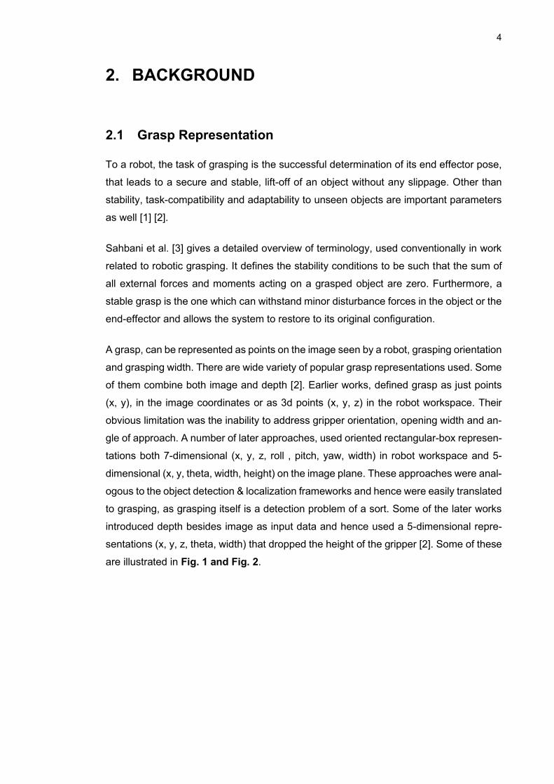
A grasp, can be represented as points on the image seen by a robot, grasping orientation
and grasping width. There are wide variety of popular grasp representations used. Some
of them combine both image and depth [2]. Earlier works, defined grasp as just points
(x, y), in the image coordinates or as 3d points (x, y, z) in the robot workspace. Their
obvious limitation was the inability to address gripper orientation, opening width and an-
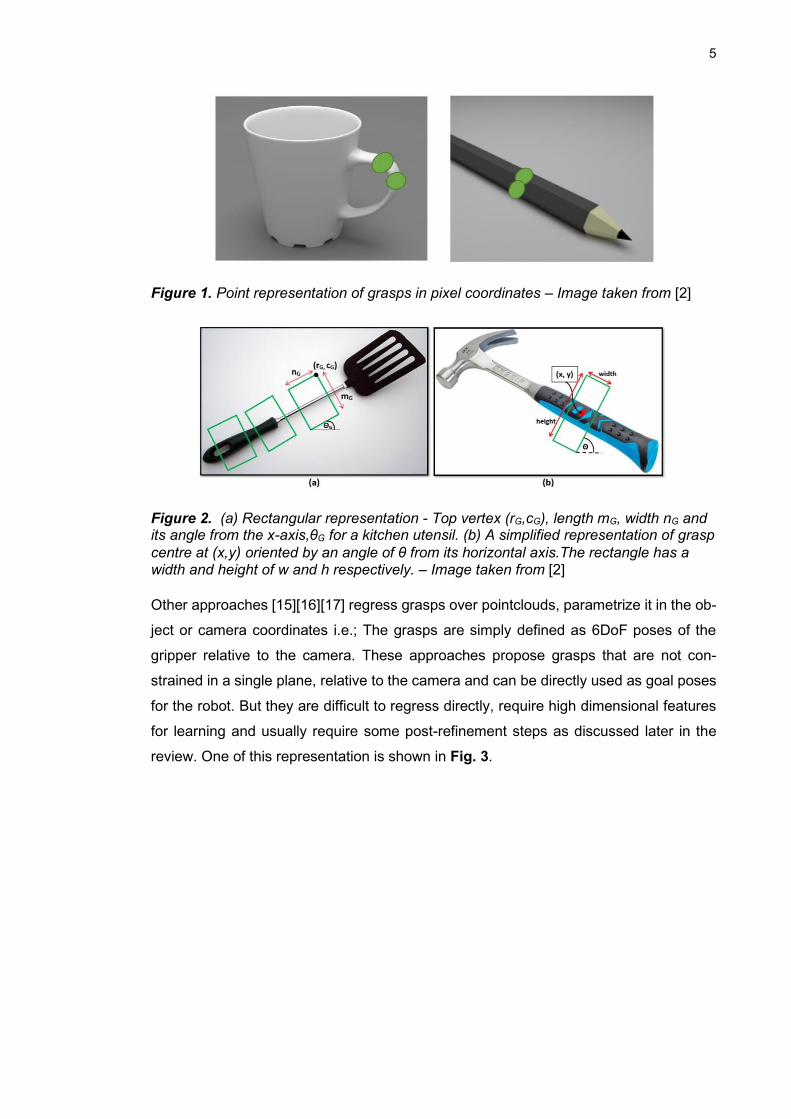
gle of approach. A number of later approaches, used oriented rectangular-box represen-
tations both 7-dimensional (x, y, z, roll , pitch, yaw, width) in robot workspace and 5-
dimensional (x, y, theta, width, height) on the image plane. These approaches were anal-
ogous to the object detection & localization frameworks and hence were easily translated
to grasping, as grasping itself is a detection problem of a sort. Some of the later works
introduced depth besides image as input data and hence used a 5-dimensional repre-
sentations (x, y, z, theta, width) that dropped the height of the gripper [2]. Some of these
are illustrated in Fig. 1 and Fig. 2.
5
Figure 1. Point representation of grasps in pixel coordinates – Image taken from [2]
Figure 2. (a) Rectangular representation - Top vertex (rG,cG), length mG, width nG and its angle from the x-axis,θG for a kitchen utensil. (b) A simplified representation of grasp
centre at (x,y) oriented by an angle of θ from its horizontal axis.The rectangle has a width and height of w and h respectively. – Image taken from [2]
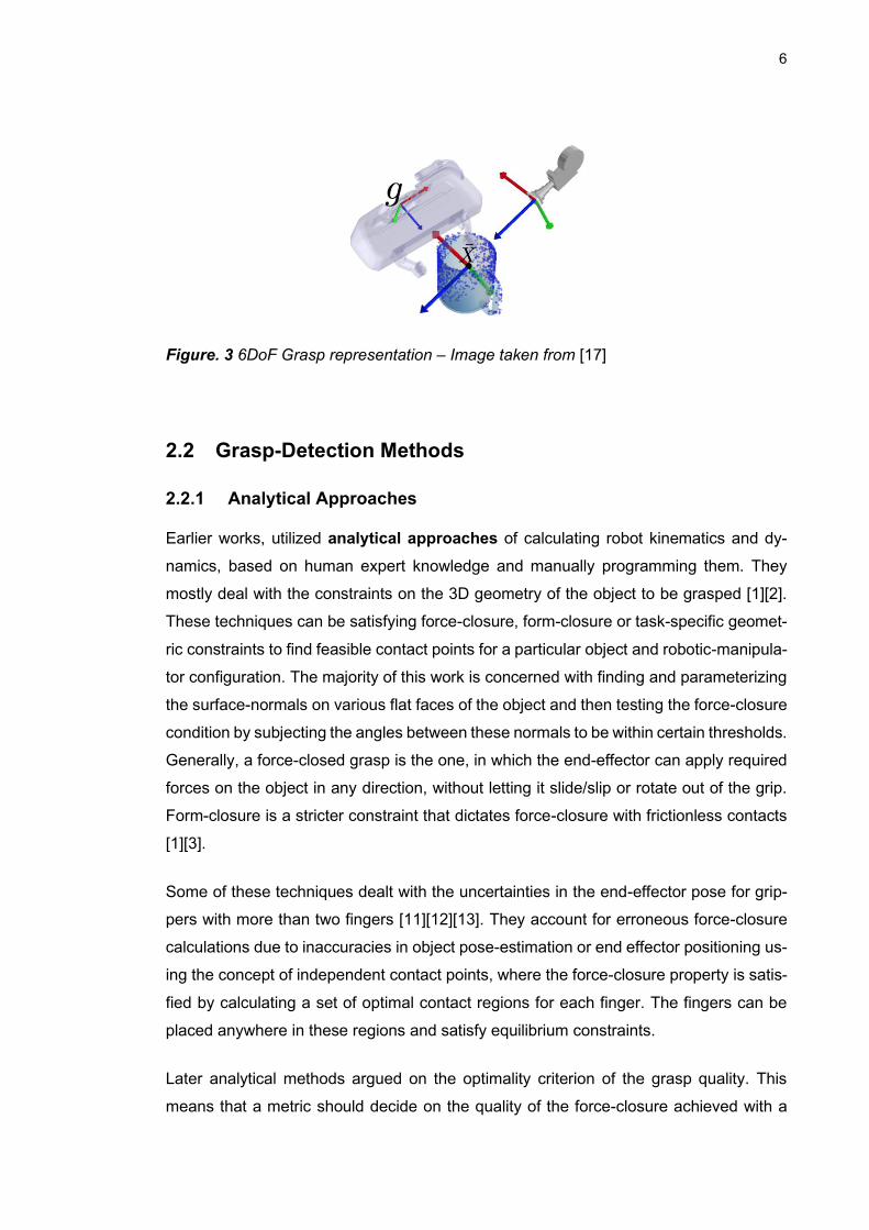
Other approaches [15][16][17] regress grasps over pointclouds, parametrize it in the ob-
ject or camera coordinates i.e.; The grasps are simply defined as 6DoF poses of the
gripper relative to the camera. These approaches propose grasps that are not con-
strained in a single plane, relative to the camera and can be directly used as goal poses
for the robot. But they are difficult to regress directly, require high dimensional features
for learning and usually require some post-refinement steps as discussed later in the
review. One of this representation is shown in Fig. 3.
6
Figure. 3 6DoF Grasp representation – Image taken from [17]
2.2 Grasp-Detection Methods
2.2.1 Analytical Approaches
Earlier works, utilized analytical approaches of calculating robot kinematics and dy-
namics, based on human expert knowledge and manually programming them. They
mostly deal with the constraints on the 3D geometry of the object to be grasped [1][2].
These techniques can be satisfying force-closure, form-closure or task-specific geomet-
ric constraints to find feasible contact points for a particular object and robotic-manipula-
tor configuration. The majority of this work is concerned with finding and parameterizing
the surface-normals on various flat faces of the object and then testing the force-closure
condition by subjecting the angles between these normals to be within certain thresholds.
Generally, a force-closed grasp is the one, in which the end-effector can apply required
forces on the object in any direction, without letting it slide/slip or rotate out of the grip.
Form-closure is a stricter constraint that dictates force-closure with frictionless contacts
[1][3].
Some of these techniques dealt with the uncertainties in the end-effector pose for grip-
pers with more than two fingers [11][12][13]. They account for erroneous force-closure
calculations due to inaccuracies in object pose-estimation or end effector positioning us-
ing the concept of independent contact points, where the force-closure property is satis-
fied by calculating a set of optimal contact regions for each finger. The fingers can be
placed anywhere in these regions and satisfy equilibrium constraints.
Later analytical methods argued on the optimality criterion of the grasp quality. This
means that a metric should decide on the quality of the force-closure achieved with a
7
certain grasp i.e., how close the grasp is, to losing its force-closure, given a particular
object geometry and hand configuration. These techniques used convex optimization in
the wrench-space of an object, to find a contact points and approach-vector that maxim-
ized the resistance to external wrenches applied on the object, hence quantifying the
force-closure of a grasp. The concept of grasp wrench space was introduced by Kirkpat-
rick et el. [18], where the efficiency of a grasp is defined by the radius of the largest
sphere that can be constrained inside the convex hull, formed by the contact point
wrenches of the said grasp.
These search-problems were tedious and required huge computing power and time.
Hence, heuristics were introduced in later techniques, to filter out vast majority of candi-
dates from the search space. Some techniques speculated on task-specific modeling of
the wrench space and hence pre-calculated grasps and trajectories were to be used [3].
These approaches, while being effective and elaborate, are quite laborious, task specific
and do not cope well with changes in the environment [1][2][3][4]. Moreover, due to the
uncertainty in modeling the sensor and actuator noises, the relative location of object
and end-effector were highly approximated. These techniques relied heavily on the pre-
cision of available geometric and physical models of the objects. In addition, surface
properties like friction coefficients, weight, weight distribution and center of mass that
play fundamental role in determining a good grasp, are not always known accurately and
adding them to the model, makes it’s analytical solution even more complex and time-
consuming [4].
Very recently, it has been studied that these analytical modeling methods and metrics
alone were not good measures of grasp as they do not adapt very well to the challenges
that are faced during execution, the uncertainties in dynamic behavior and the unstruc-
tured environment. It is inevitable that these approaches are to be tested as exhaustively
on real robots, as they are formulated to be completely certain about them. Even that
certainty varies a lot among different kinds of grippers, objects and environments. So in
the last decade, there was a general push towards machine-learning approaches which
present a more abstract, easy-to-test indirect approach of evaluating grasp success on
a huge variety of objects, grippers and environmental conditions [4].
8
2.2.2 Data-driven Approaches
Difficulty of modeling a task, object geometry and the computational complexity in solving
for these models, paved way towards a plethora of new approaches that were predomi-
nantly data-driven and based on machine-learning and deep-learning techniques
[1][2][3][4].
More recently, generalized/empirical approaches, that use machine learning techniques
like Regression techniques, Gaussian process, Gaussian mixture models, and Support
Vector Machines, have been successfully applied to the robotic manipulation tasks with
great adaptability and almost zero requirement of manual modeling. Even more so, deep
learning methods, have proved significant advancement over other empirical methods
[2].
The shift from complex mathematical modeling of the grasping itself, towards the indirect
mapping of perceptual features with grasp-success was made possible by availability of
high quality 3D cameras and depth sensors, increasingly powerful computational re-
sources and a substantial amount of invaluable research in deep neural networks, CNNs
and transfer learning in the last few decades [1][2]. The biggest advantage these meth-
ods provided were the vast horizons of possibilities which could be tested both in simu-
lation and real execution, using data from real sensors as well as synthesized data.
These methods don’t explicitly guarantee equilibrium, dexterity or stability but the prem-
ise of testing all of these criteria and the dynamics, based solely on sensor data, object
representation and carefully designed object features provide a hefty and convenient
way of studying grasp synthesis [4].
Empirical approaches are further divided into two different categories:-
• Object-Centered
These techniques learn the visual or depth features of the objects using Transfer learning
from other closely related domains like object detection or instance segmentation. These
features are then used to form an association between graspable regions and the ma-
nipulator parameters. The parameters learned by these methods are related to the ge-
ometry of the object and the ground truth data is usually annotated manually or through
simulation [3]. These methods have their own different sub-categories, based on the
level of familiarity with the target object. The three general divisions throughout the lit-
erature are [1][4]:
a) Known objects: A particular object instance is seen before and grasps are prede-
fined based on it’s geometry. The grasp-estimation in this context is just object-pose
estimation combined with grasp transference from object to world coordinates.
9
b) Familiar objects: Different instances(with a certain level of similarity) of a particular
object category are queried with the assumption that new objects have a degree of
similarity of to the previously seen categories. A normalized object representation per
category is used to estimate similarity measure and transfer predefined grasps from
previously seen instances to the newer ones.
c) Unknown objects: Objects are completely novel and there is no access to prede-
fined grasps on any CAD model or normalized representation. These methods work
with the salient features of sensory data and learn to co-relate, structure in the scene
with the grasp ranking.
• Human-centered
Also known as demonstration-learning, these techniques rely on observing humans, per-
forming the grasping task. These techniques learn the motion, shape, joint trajectories
and grasping points of the demonstrator’s hand and try to replicate the task. They use
various methods of tracking the demonstrator’s hand using either visual or motion sen-
sors to map the hand’s movements into a viable wrench space for the robot to manipulate
in. The parameters learned by these methods are mainly task-specific hand postures
and motion primitives. Ground truth data is in the form of grasping-trials performed on
real-objects or in virtual reality. Some of these techniques also incorporate object-geo-
metrical features or graspable regions but the main idea is focused on learning from the
actions generated by a demonstrator [3].
• Hybrid-Approaches
Bohg et al. [4] describe a new set of methods, developed relatively recently, using grasp-
ing-trials on a real-robot or in a simulation environment. Firstly, these methods don’t rely
on the limited accuracy or quantity of label-data, manually annotated by humans, as good
grasp candidates on images or depth-maps. So, they generalize much better than Ob-
ject-Centric methods. Secondly, unlike other human-centered methods, they surpass the
complexity of transferring data, learned from human-actions, to real robots. In these
methods, an exhaustive number of random or heuristically determined grasps are sam-
pled on the object surface and executed on a real robot or a simulated one(with enough
environmental constraints). The results of these grasp executions are then marked either
as binary, failure or success, labels or as quantitative metrics that satisfy wrench-space
constraints of the particular robot.
Gupta et el. [19] present a major contribution in this domain by collecting around 700
hours of grasp trials on Baxter robot, using a wide variety of cluttered and occluded en-
vironments. Although they reduce the initial search space for grasps through Region-of-

10
Interest sampling but the huge number of grasps tried on each object under multiple
conditions with real-execution, provides a very robust way of annotating grasps before
training.
Guo et el. [20] took this a step further by incorporating tactile data collected during grasp
execution in order to enhance the network’s learning capability of visual features. Both,
during data-collection and training, their network uses tactile data from the gripper as a
direct measure of stability of a grasp and the contribution of each visual feature in pre-
dicting the success of the grasp.
These techniques combine both feature-learning and action-learning from the methods
mentioned above but collecting data and training them is exhaustive and time-consum-
ing. Moreover, the generalization capability of these methods depend upon:
1. The criteria used for sampling grasp candidates before the trial
2. The quality metrics used to evaluate the success after each trial.
The main focus of this thesis is only on Object-centric methods so the following discus-
sion, comparison, implementation details and results are all related to various methods
only from this category. Moreover, a general difference among these techniques needs
to be contrasted, before concluding the utility of one over other for our use-case.
2.3 Grasp detection for Known Objects
This sub-domain of Object-centric methods have been researched most extensively be-
cause they come as a direct extension of object-detection and object-pose-estimation
methods. Because they rely on accurate CAD models of the target objects, available for
training, the grasp-detection becomes a direct analogous of pose-estimation [1].
Widespread work has been done in object-detection, object-segmentation and pose-re-
gression. Earlier works in these, were disjoint implementations of object-detection,
bounding-box regression and pose-estimation. In the last decade, state-of-the art tech-
niques in 2D and 3D object-detection like Mask-RCNN [21], Faster-RCNN [22] and FPN
[23] have made possible highly accurate, robust and real-time object-detection and ob-
ject-mask-segmentation possible with immaculate robustness to occlusions, lighting var-
iations, scale variation and intra-class variation.
These advancements led to the extensive developments of a wide variety of 2-stage and
one-shot methods for 6D-object pose estimation with both RGB & RGBD data. The basic
11
categorization of these methods, based on variation in visual or depth features and net-
work architecture is as follows:-
2.3.1 Correspondence-based methods
These methods use correspondence of 2D features in RGB images or 3D features in
RGBD images, with the features found by rendering known CAD models from different
angles. Well-known 2D descriptors like SIFT [24], SURF [25] and ORB [26]
are used for 2D-3D correspondence. When depth information is available, popular 3D-
descriptors like FPFH[27] and SHOT[28] can be utilized for 3D-3D correspondence. After
finding initial correspondences, the pose-estimation reduces to a PnP or a partial regis-
tration problem. These methods utilize local image descriptors, so a rich texture is re-
quired, for the object features to be distinguished and matched properly with their coun-
terparts. This makes them really sensitive to occlusions, foreground clutter and varying
light-conditions. [1]
Some of the noticeable improvements upon traditional problems in these methods have
been recently proposed. Quang-Hieu et el. [29] proposed a new method of embedding
2D and 3D input features into shared latent-space representation. These so-called
“cross-domain” descriptors are more discriminative and show much more promise than
training on individual 2D or 3D descriptors. Yinlin Hu et el. [30] used segmentation-
driven feature extraction for 2D-to-3D correspondence. Their method shows robustness
to occlusions and lack of texture, as the local descriptors they extract have their respec-
tive confidence levels i.e., The areas of the objects more clearly visible, contribute more
to the pose prediction. These confidence values for local image patches are made pos-
sible by the combination of mask segmentation. A generic layout of these methods is
shown in Fig. 4.
12
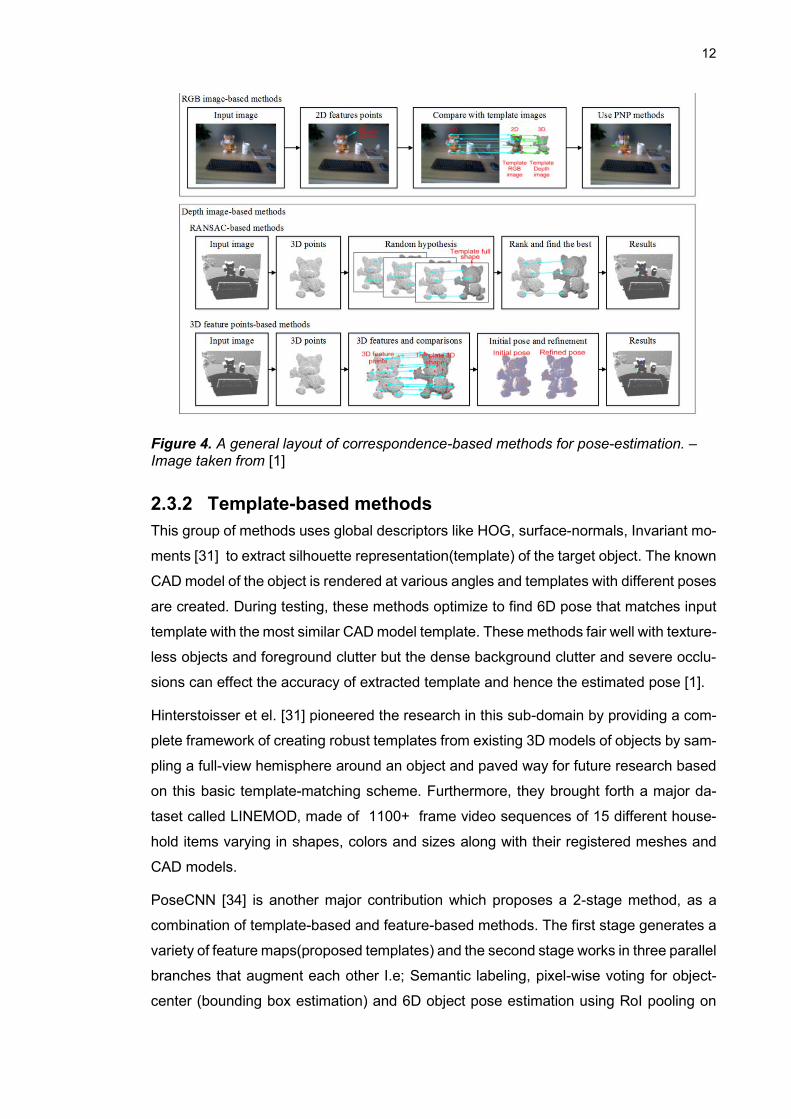
Figure 4. A general layout of correspondence-based methods for pose-estimation. – Image taken from [1]
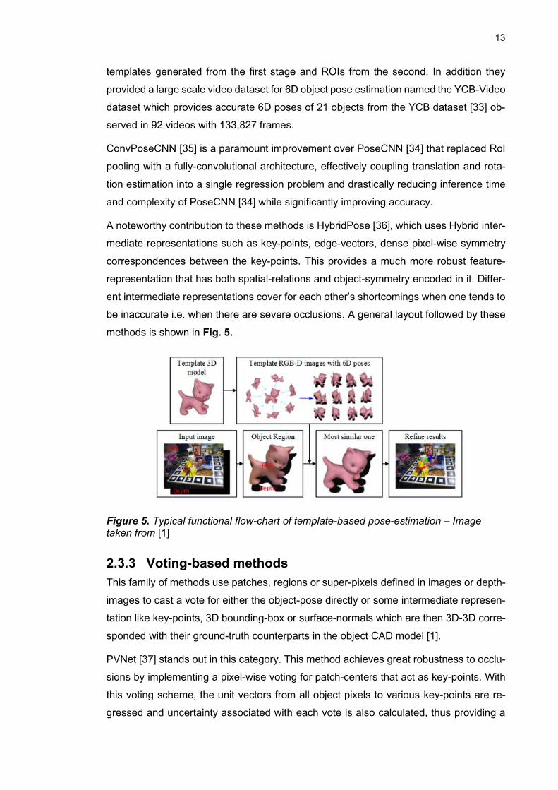
2.3.2 Template-based methods
This group of methods uses global descriptors like HOG, surface-normals, Invariant mo-
ments [31] to extract silhouette representation(template) of the target object. The known
CAD model of the object is rendered at various angles and templates with different poses
are created. During testing, these methods optimize to find 6D pose that matches input
template with the most similar CAD model template. These methods fair well with texture-
less objects and foreground clutter but the dense background clutter and severe occlu-
sions can effect the accuracy of extracted template and hence the estimated pose [1].
Hinterstoisser et el. [31] pioneered the research in this sub-domain by providing a com-
plete framework of creating robust templates from existing 3D models of objects by sam-
pling a full-view hemisphere around an object and paved way for future research based
on this basic template-matching scheme. Furthermore, they brought forth a major da-
taset called LINEMOD, made of 1100+ frame video sequences of 15 different house-
hold items varying in shapes, colors and sizes along with their registered meshes and
CAD models.
PoseCNN [34] is another major contribution which proposes a 2-stage method, as a
combination of template-based and feature-based methods. The first stage generates a
variety of feature maps(proposed templates) and the second stage works in three parallel
branches that augment each other I.e; Semantic labeling, pixel-wise voting for object-
center (bounding box estimation) and 6D object pose estimation using RoI pooling on
13
templates generated from the first stage and ROIs from the second. In addition they
provided a large scale video dataset for 6D object pose estimation named the YCB-Video
dataset which provides accurate 6D poses of 21 objects from the YCB dataset [33] ob-
served in 92 videos with 133,827 frames.
ConvPoseCNN [35] is a paramount improvement over PoseCNN [34] that replaced RoI
pooling with a fully-convolutional architecture, effectively coupling translation and rota-
tion estimation into a single regression problem and drastically reducing inference time
and complexity of PoseCNN [34] while significantly improving accuracy.
A noteworthy contribution to these methods is HybridPose [36], which uses Hybrid inter-
mediate representations such as key-points, edge-vectors, dense pixel-wise symmetry
correspondences between the key-points. This provides a much more robust feature-
representation that has both spatial-relations and object-symmetry encoded in it. Differ-
ent intermediate representations cover for each other’s shortcomings when one tends to
be inaccurate i.e. when there are severe occlusions. A general layout followed by these
methods is shown in Fig. 5.
Figure 5. Typical functional flow-chart of template-based pose-estimation – Image taken from [1]
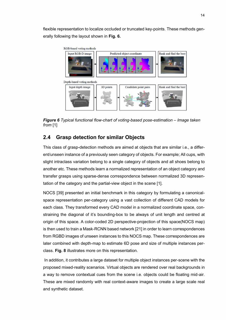
2.3.3 Voting-based methods
This family of methods use patches, regions or super-pixels defined in images or depth-
images to cast a vote for either the object-pose directly or some intermediate represen-
tation like key-points, 3D bounding-box or surface-normals which are then 3D-3D corre-
sponded with their ground-truth counterparts in the object CAD model [1].
PVNet [37] stands out in this category. This method achieves great robustness to occlu-
sions by implementing a pixel-wise voting for patch-centers that act as key-points. With
this voting scheme, the unit vectors from all object pixels to various key-points are re-
gressed and uncertainty associated with each vote is also calculated, thus providing a
14
flexible representation to localize occluded or truncated key-points. These methods gen-
erally following the layout shown in Fig. 6.
Figure 6 Typical functional flow-chart of voting-based pose-estimation – Image taken from [1]
2.4 Grasp detection for similar Objects
This class of grasp-detection methods are aimed at objects that are similar i.e., a differ-
ent/unseen instance of a previously seen category of objects. For example; All cups, with
slight intraclass variation belong to a single category of objects and all shoes belong to
another etc. These methods learn a normalized representation of an object category and
transfer grasps using sparse-dense correspondence between normalized 3D represen-
tation of the category and the partial-view object in the scene [1].
NOCS [39] presented an initial benchmark in this category by formulating a canonical-
space representation per-category using a vast collection of different CAD models for
each class. They transformed every CAD model in a normalized coordinate space, con-
straining the diagonal of it’s bounding-box to be always of unit length and centred at
origin of this space. A color-coded 2D perspective-projection of this space(NOCS map)
is then used to train a Mask-RCNN based network [21] in order to learn correspondences
from RGBD images of unseen instances to this NOCS map. These correspondences are
later combined with depth-map to estimate 6D pose and size of multiple instances per-
class. Fig. 8 illustrates more on this representation.
In addition, it contributes a large dataset for multiple object instances per-scene with the
proposed mixed-reality scenarios. Virtual objects are rendered over real backgrounds in
a way to remove contextual cues from the scene i.e. objects could be floating mid-air.
These are mixed randomly with real context-aware images to create a large scale real
and synthetic dataset.
15
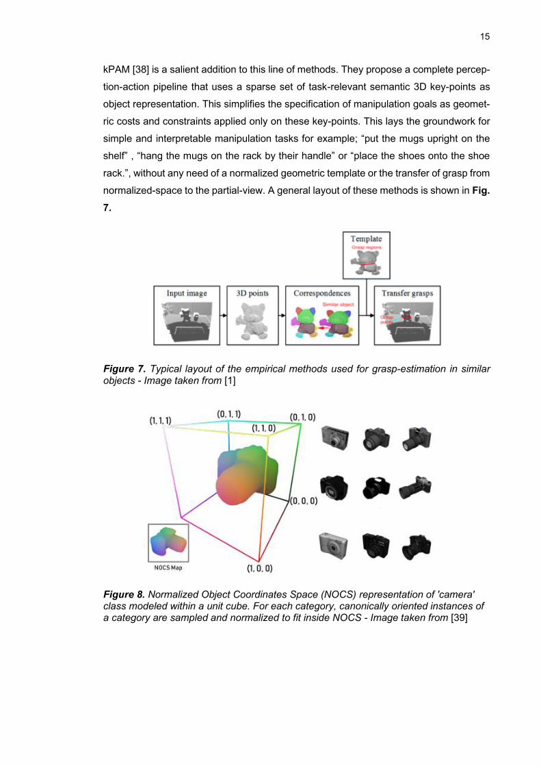
kPAM [38] is a salient addition to this line of methods. They propose a complete percep-
tion-action pipeline that uses a sparse set of task-relevant semantic 3D key-points as
object representation. This simplifies the specification of manipulation goals as geomet-
ric costs and constraints applied only on these key-points. This lays the groundwork for
simple and interpretable manipulation tasks for example; “put the mugs upright on the
shelf” , “hang the mugs on the rack by their handle” or “place the shoes onto the shoe
rack.”, without any need of a normalized geometric template or the transfer of grasp from
normalized-space to the partial-view. A general layout of these methods is shown in Fig.
7.
Figure 7. Typical layout of the empirical methods used for grasp-estimation in similar objects - Image taken from [1]
Figure 8. Normalized Object Coordinates Space (NOCS) representation of 'camera' class modeled within a unit cube. For each category, canonically oriented instances of a category are sampled and normalized to fit inside NOCS - Image taken from [39]
16
2.5 Grasp detection for novel Objects
In this class of methods, there is no existing knowledge of object geometry and grasps
are estimated directly from image and depth data. Majority of these methods use geo-
metric properties inferred from input perceptual data, as a measure of grasp success [1].
Most of these were developed in end-to-end fashion, learning from a database of grasps
on a huge number of different object models. These grasps are sampled exhaustively
around the objects and are either evaluated on classical grasp metrics, such as epsilon
quality metric [40], manually annotated with their success measures by humans or tested
with real execution. [41][42]. The premise of these methods lies in the later training stage,
where a deep neural network learns to produce robust grasps in general. The emphasis
is on learning a robustness function that ranks a candidate grasp for various quality met-
rics. The initial candidate grasps could be generated using various sampling schemes
which are discussed in chapter 4.
DexNet 1.0 [41] and DexNet 2.0 [42] are two pioneering works that utilized this strategy
and created huge datasets of 3D object models for learning objective functions that min-
imize grasp failure, in presence of object and gripper position uncertainties and camera
noises. Enforcing constraints like collision avoidance, approach-angle threshold and
gripper-roll threshold, these methods provided a baseline for co-relating object geometry
from RGBD images [41] or point-clouds [42] with grasp robustness.
Earlier methods in this class were 2-stage cascaded approaches, with grasp-classifica-
tion at first step working as a faster network having lesser parameters, exhaustively
searching for Regions-of-Interests. These are later evaluated at second step by a Grasp-
detection network which is slower and has to run on fewer detections. [43]
Pinto et al. [19] minimized grasp proposals by only using grasp-points (x, y) and crop-
ping an image-patch around this point. For the grasp angle in 2D-plane, predictions were
divided between 18 different output-bins with increments of 10 degrees each.
Park et al. [44] used cascaded STNs [45] for a stepwise grasp-detection. The first STN
proposed 4 crops as feasible grasp regions which are then fed to cascade of two STNs,
one for angle-estimation and last-one for scaling and crop adjustment. These fine-tuned
proposals are then independently fed to a classifier to predict the best one.
Later on, one-shot methods proved more reliable and faster with a variety of methods
using the robustness-classifiers from 2-stage methods and training on the gradients gen-
erated by these methods. The difference is that, the learning is optimized towards directly
17
regressing a best grasp-candidate instead of performing an exhaustive search in the first
place. [1]
[46] and [47] are excellent examples in this work that used fully-convolutional architec-
ture, to regress graspable bounding-boxes bypassing the need of any sliding window
detectors or convex-hull-sampling approaches.
A recent addition is that of GQ-STN [48] which combines GQ-CNN proposed in [42] i.e.
Grasp-Quality convolutional network with STN [45] to produce a grasp-configuration that
satisfies a heuristic-based robustness evaluation metric called Robust Ferrari-Canny
[48].This metric estimates largest disturbance wrench of the contacts, that can be re-
sisted in all directions. Geometrically, it specifies radius of the largest ball, with it’s center
at origin, constrained to be within the convex hull of the unit contact wrenches. This force-
closure-based metric is one of the most widely used grasp quality metric. This same
metric has been used in DexNet 2.0 and many other pointcloud-based grasp-detection
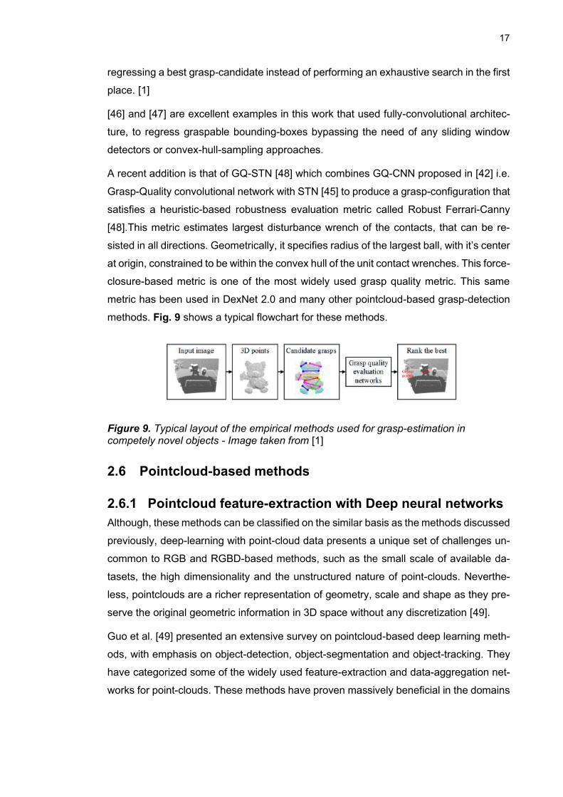
methods. Fig. 9 shows a typical flowchart for these methods.
Figure 9. Typical layout of the empirical methods used for grasp-estimation in competely novel objects - Image taken from [1]
2.6 Pointcloud-based methods
2.6.1 Pointcloud feature-extraction with Deep neural networks
Although, these methods can be classified on the similar basis as the methods discussed
previously, deep-learning with point-cloud data presents a unique set of challenges un-
common to RGB and RGBD-based methods, such as the small scale of available da-
tasets, the high dimensionality and the unstructured nature of point-clouds. Neverthe-
less, pointclouds are a richer representation of geometry, scale and shape as they pre-
serve the original geometric information in 3D space without any discretization [49].
Guo et al. [49] presented an extensive survey on pointcloud-based deep learning meth-
ods, with emphasis on object-detection, object-segmentation and object-tracking. They
have categorized some of the widely used feature-extraction and data-aggregation net-
works for point-clouds. These methods have proven massively beneficial in the domains
18
of object-pose estimation and grasp detection as well. They highlighted a Multi-view rep-
resentation that has been used in some of the baseline grasp-detection methods.
Ten pas et al. [15] used such representation in the form of a global grasp-descriptor that
employs surface normals and multiple views of object point-cloud to encode grasps as
stacked multi-channel images. In order to cover geometry of the observed surfaces and
unobserved volumes in gripper’s closing region, voxelized representation of gripper’s
closing region is projected onto a plane perpendicular to the gripper’s approach axis. As
a result, an average height-map of occupied points, unobserved points and average sur-
face normals are generated for the CNN to train on. The dataset they produce has it’s
ground-truth grasp labels annotated using antipodal grasp criteria i.e. “An antipodal
grasp requires the pair of contacts to be such that line connecting the points is nearly
parallel( within a threshold) to the direction of finger-closing”. These grasps are initially
sampled using uniform sampling scheme discussed in 3.7.
VoxelNet [50] is another important contribution which introduced a voxel-feature-encod-
ing as the volumetric representation mentioned in [49]. Their end-to-end trainable archi-
tecture provides a massive improvement over information bottlenecks that come with
hand-crafted 3D descriptors and limited adaption of projection-based 3D descriptors to
complex shapes. The cascade of their voxel-feature-encoding layers and middle-CNN-
layers combines both point-wise features and locally aggregated features. As a result,
point-interactions between voxels are enabled and final representation learns descriptive
shape information.
19
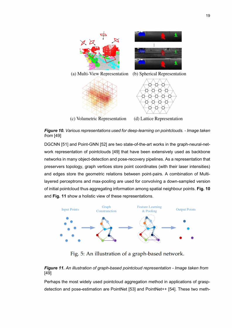
Figure 10. Various representations used for deep-learning on pointclouds. - Image taken from [49]
DGCNN [51] and Point-GNN [52] are two state-of-the-art works in the graph-neural-net-
work representation of pointclouds [49] that have been extensively used as backbone
networks in many object-detection and pose-recovery pipelines. As a representation that
preservers topology, graph vertices store point coordinates (with their laser intensities)
and edges store the geometric relations between point-pairs. A combination of Multi-
layered perceptrons and max-pooling are used for convolving a down-sampled version
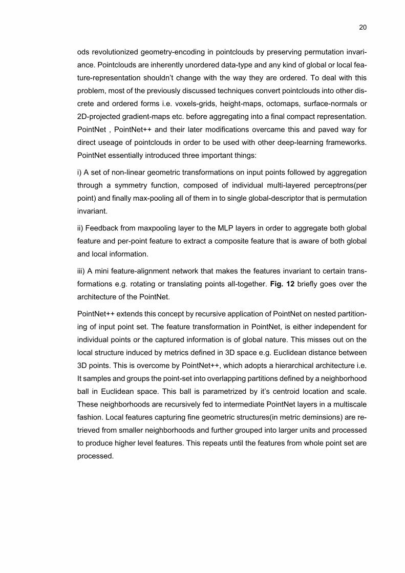
of initial pointcloud thus aggregating information among spatial neighbour points. Fig. 10
and Fig. 11 show a holistic view of these representations.
Figure 11. An illustration of graph-based pointcloud representation - Image taken from [49]
Perhaps the most widely used pointcloud aggregation method in applications of grasp-
detection and pose-estimation are PointNet [53] and PointNet++ [54]. These two meth-
20
ods revolutionized geometry-encoding in pointclouds by preserving permutation invari-
ance. Pointclouds are inherently unordered data-type and any kind of global or local fea-
ture-representation shouldn’t change with the way they are ordered. To deal with this
problem, most of the previously discussed techniques convert pointclouds into other dis-
crete and ordered forms i.e. voxels-grids, height-maps, octomaps, surface-normals or
2D-projected gradient-maps etc. before aggregating into a final compact representation.
PointNet , PointNet++ and their later modifications overcame this and paved way for
direct useage of pointclouds in order to be used with other deep-learning frameworks.
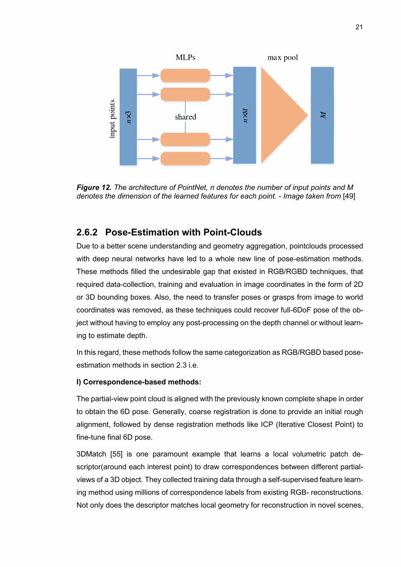
PointNet essentially introduced three important things:
i) A set of non-linear geometric transformations on input points followed by aggregation
through a symmetry function, composed of individual multi-layered perceptrons(per
point) and finally max-pooling all of them in to single global-descriptor that is permutation
invariant.
ii) Feedback from maxpooling layer to the MLP layers in order to aggregate both global
feature and per-point feature to extract a composite feature that is aware of both global
and local information.
iii) A mini feature-alignment network that makes the features invariant to certain trans-
formations e.g. rotating or translating points all-together. Fig. 12 briefly goes over the
architecture of the PointNet.
PointNet++ extends this concept by recursive application of PointNet on nested partition-
ing of input point set. The feature transformation in PointNet, is either independent for
individual points or the captured information is of global nature. This misses out on the
local structure induced by metrics defined in 3D space e.g. Euclidean distance between
3D points. This is overcome by PointNet++, which adopts a hierarchical architecture i.e.
It samples and groups the point-set into overlapping partitions defined by a neighborhood
ball in Euclidean space. This ball is parametrized by it’s centroid location and scale.
These neighborhoods are recursively fed to intermediate PointNet layers in a multiscale
fashion. Local features capturing fine geometric structures(in metric deminsions) are re-
trieved from smaller neighborhoods and further grouped into larger units and processed
to produce higher level features. This repeats until the features from whole point set are
processed.
21
Figure 12. The architecture of PointNet, n denotes the number of input points and M denotes the dimension of the learned features for each point. - Image taken from [49]
2.6.2 Pose-Estimation with Point-Clouds
Due to a better scene understanding and geometry aggregation, pointclouds processed
with deep neural networks have led to a whole new line of pose-estimation methods.
These methods filled the undesirable gap that existed in RGB/RGBD techniques, that
required data-collection, training and evaluation in image coordinates in the form of 2D
or 3D bounding boxes. Also, the need to transfer poses or grasps from image to world
coordinates was removed, as these techniques could recover full-6DoF pose of the ob-
ject without having to employ any post-processing on the depth channel or without learn-
ing to estimate depth.
In this regard, these methods follow the same categorization as RGB/RGBD based pose-
estimation methods in section 2.3 i.e.
I) Correspondence-based methods:
The partial-view point cloud is aligned with the previously known complete shape in order
to obtain the 6D pose. Generally, coarse registration is done to provide an initial rough
alignment, followed by dense registration methods like ICP (Iterative Closest Point) to
fine-tune final 6D pose.
3DMatch [55] is one paramount example that learns a local volumetric patch de-
scriptor(around each interest point) to draw correspondences between different partial-
views of a 3D object. They collected training data through a self-supervised feature learn-
ing method using millions of correspondence labels from existing RGB- reconstructions.
Not only does the descriptor matches local geometry for reconstruction in novel scenes,
22
but also generalizes to different tasks and spatial scales (e.g. instance-level object model
alignment for the Amazon Picking Challenge, and mesh surface correspondence). They
conclude with experimentation that 3D representation better captures real-world spatial
scale and occluded regions, that are not directly encoded in 2D depth patches.
LCD [29] combined 2D and 3D modalities, embedding them into a shared latent-space
using a dual auto-encoder( one branch for encoding image and the other for pointcloud).
These are first trained separately using a photometric loss(mean squared error between
the input 2D patch and the reconstructed patch) and chamfer loss(distance between the
input pointset and the reconstructed point set) respectively. This lets each branch cap-
ture it’s own salient features. At later stage, these branches are trained jointly with a
shared triplet loss to obtain domain-invariant features. Their ablation study shows that
local cross-domain descriptors trained in a shared embedding are more discriminative
as compared with the ones acquired in individual 2D and 3D domains.
3DRegNet[56] is a noteworthy mention here. It combines classification of inlier/outlier
correspondences in 3D scans with the regression of motion parameters to solve for par-
tial-to-partial registration fine-tuned with post-refinement.
ii) Template-based methods
PointGMM [57] is one such method that uses hierarchical Gaussian mixture models to
learn class-specific shape priors( templates). The GMMs are structured features, where
distinct regions of Gaussians(in the input point-set)encode semantic spatial regions of
the shape. A neural network training on GMMs suffers from a problem of converging to
a local minima. This is overcome by a hierarchical implementation where GMMs at the
bottom focus on learning smaller spatial regions and the top-level GMMs learn over wider
regions. This feature-representation is thus compact and light in computation.
iii) Voting-based Methods
PVN3d is a recent addition to this category of methods, which is a 3D variant of the pixel-
wise voting network PVNet [37]. They extend the same pixel-wise hough-voting scheme
to 3D and learn the point-wise 3D offsets from pre-defined set of 3D keypoints in order
to fully utilize the geometric constraints of rigid body objects in 3D euclidean space. They
propose a 2-stage network with one part regressing 3D-keypoint locations and the other
for pose-parameter fitting. The MLPs used for feature extraction in key-point offset esti-
mation are shared with another parallel branch for instance semantics segmentation.
YOLOff [58] is a similar technique but takes a hybrid approach where they combine 2D
image-patch classification with 3D key-point regression. They argue that this cascaded
approach has dual-benefits, I) With patches properly classified, only relevant ones are
23
transmitted to the regression network which allows the CNN to fit using only relevant
geometric information around the object, thus speeding up the training and inference, ii)
It simplifies the need to have a sophisticated parametric loss function for training the
regression CNN.
2.6.3 Grasp-detection with Point-Clouds
These methods regress feasible grasp poses directly on the pointcloud. The grasps are
first sampled either exhaustively or based on a heuristic and scored according to various
stability criteria. Then the network learns to reproduce such grasps on unseen objects
and score them relatively. Eventually, this kind of methods learn stable grasping of ob-
jects in general rather than transferring a set of predefined or learned grasps on objects
seen during training. This removes the need of estimating the pose of the object in the
scene or any prior knowledge about the shape or canonical representation of a class of
objects. With the pointclouds, these grasps can be recovered in 6DoF without constrain-
ing the gripper to move along the image plane, as with the RGBD-based detectors.
Ten Pas et al. [15] proposed one of the very first methods that exploit the point-cloud
geometry to satisfy anti-podal grasp criteria on parallel-finger gripper. They apply a two
stage method, where grasps sampled uniformly(using a grid search) around the object
are first filtered out if either they result into a collision between hand and object or the
gripper-closing volume stays empty. In the second stage, the grasps filtered out in the
first stage are then subjected to the antipodal constraint i.e., “A pair of point contacts
with friction is antipodal if and only if the line connecting the contact points lies inside
both friction cones“ [13]. “A friction cone describes the space of normal and frictional
forces that a point contact with friction can apply to the contacted surface” [77]. Their
novel technique generates a huge amount of training data labeled without any manual
intervention. Using only their antipodal-sampling technique without any machine learning
they achieve 73% success rate in grasping novel objects in dense clutter. This set a
critical baseline for future methods learning to grasp based on pointcloud geometry. They
also trained a CNN based classifier on 15-channel feature-representation mentioned in
3.6.1 on both synthetic and real pointclouds. They provide a comprehensive set of results
on a variety of different ablations of their algorithm. Grasp classification accuracy is
measured at 99% precision threshold compared between 3 different feature-represen-
tations and 2 different datasets(real and synthetic). They also provide training sets and
accuracy results on cases where the algorithm has prior knowledge of object shape i.e.,
The network is trained either on all box-shaped objects or on all cylindrical objects. Their
best ablation gives over 90% accuracy. Finally their dense clutter experiments report
24
results based on 2 different pointcloud acquisition strategies(active and passive) and
with or without grasp-selection. For grasp-selection, they propose a cost function for
scoring based on:
i) Height of grasps i.e., grasps on top of the pile are preferred
ii) Approach direction i.e., side grasps are more successful.
Iii) Distance traveled by arm in configuration space to reach the grasp.
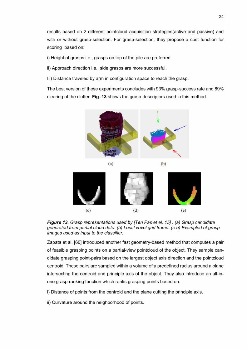
The best version of these experiments concludes with 93% grasp-success rate and 89%
clearing of the clutter. Fig .13 shows the grasp-descriptors used in this method.
Figure 13. Grasp representations used by [Ten Pas et el. 15] . (a) Grasp candidate generated from partial cloud data. (b) Local voxel grid frame. (c-e) Exampled of grasp images used as input to the classifier.
Zapata et al. [60] introduced another fast geometry-based method that computes a pair
of feasible grasping points on a partial-view pointcloud of the object. They sample can-
didate grasping point-pairs based on the largest object axis direction and the pointcloud
centroid. These pairs are sampled within a volume of a predefined radius around a plane
intersecting the centroid and principle axis of the object. They also introduce an all-in-
one grasp-ranking function which ranks grasping points based on:
i) Distance of points from the centroid and the plane cutting the principle axis.
ii) Curvature around the neighborhood of points.

25
Iii) Antipodal criteria: The collinearity of forces applied at contact points I.e, Surface nor-
mals at these points should be nearly parallel gripper’s closing direction.
Iv) Angle between cutting plane and the line connecting contact points.
PointNetGPD [16] extended the same concept of using pointcloud geometry by aug-
menting feature-extraction with PointNet [53] architecture i.e., geometrical analysis di-
rectly from pointcloud without the need of any multi-view CNN or 3D-CNN. They present
an improvement over methods with hand-crafted features [15] in terms of accuracy, over-
fitting and robustness to sensor noise. They present a continuous grasp quality metric(ra-
ther than binary) based on friction coefficient and grasp-wrench-space radius calculated
directly from the pointcloud and use this metric to label grasps on YCB [33] training da-
taset. Their network learns to predict this grasp quality by using PointNet feature-extrac-
tion on pointcloud segment in gripper’s closing region. For sampling initial grasps before
evaluation, they propose a heuristic-based variation to the GPD’s [15] sampling method-
ology. Fig. 14 illustrates the architecture used in this method.
Figure 14. Architecture of PointNetGPD [16], where grasps are represented by points inside the gripper's closing region. These points are converted to gripper coordinate frame and are passed through a PointNet-based network which extracts global grasp-descriptor features.
6-DOF GraspNet [17] introduced another unique improvement by employing two net-
works based on PointNet++ architecture, much like GANs [61]. A general structure of a
PointNet++-based networked is shown in Fig. 15. One is a generator network(Variational
Auto-encoder) that learns to generate positive grasps by encoding PointNet++ features
of the object pointcloud in a latent space. This latent space represents the space of all
the successful grasps around an object. The generative model trains on all positive sam-
ples around an object and learns to maximize the likelihood of finding feasible grasps,
approximating a normal distribution within the latent space. The second is an evaluator
network which learns to assign a probability of success to the grasp generated by the
first network. This network learns by encoding PointNet features of a unified pointcloud
i.e., Both the object and gripper( in it’s grasp pose) pointclouds. This results in a better
association of every point, it’s neighborhood and the grasp pose. The evaluator is trained
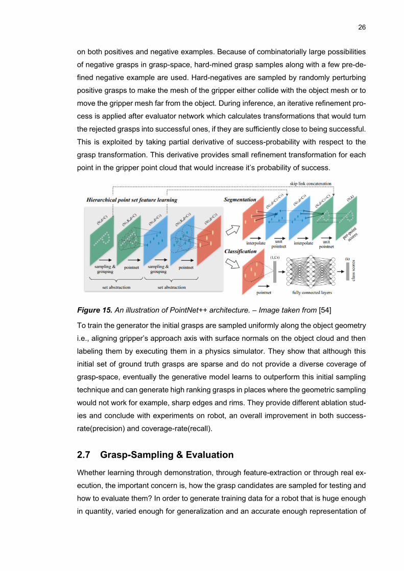
26
on both positives and negative examples. Because of combinatorially large possibilities
of negative grasps in grasp-space, hard-mined grasp samples along with a few pre-de-
fined negative example are used. Hard-negatives are sampled by randomly perturbing
positive grasps to make the mesh of the gripper either collide with the object mesh or to
move the gripper mesh far from the object. During inference, an iterative refinement pro-
cess is applied after evaluator network which calculates transformations that would turn
the rejected grasps into successful ones, if they are sufficiently close to being successful.
This is exploited by taking partial derivative of success-probability with respect to the
grasp transformation. This derivative provides small refinement transformation for each
point in the gripper point cloud that would increase it’s probability of success.
Figure 15. An illustration of PointNet++ architecture. – Image taken from [54]
To train the generator the initial grasps are sampled uniformly along the object geometry
i.e., aligning gripper’s approach axis with surface normals on the object cloud and then
labeling them by executing them in a physics simulator. They show that although this
initial set of ground truth grasps are sparse and do not provide a diverse coverage of
grasp-space, eventually the generative model learns to outperform this initial sampling
technique and can generate high ranking grasps in places where the geometric sampling
would not work for example, sharp edges and rims. They provide different ablation stud-
ies and conclude with experiments on robot, an overall improvement in both success-
rate(precision) and coverage-rate(recall).
2.7 Grasp-Sampling & Evaluation
Whether learning through demonstration, through feature-extraction or through real ex-
ecution, the important concern is, how the grasp candidates are sampled for testing and
how to evaluate them? In order to generate training data for a robot that is huge enough
in quantity, varied enough for generalization and an accurate enough representation of
27
task constraints, some efficient heuristic measures are needed to search through a
space of thousands of potentially viable grasps [5]. Even after the initial selection of these
candidates, effective evaluation of these grasps and the metrics of robot’s performance
on them determines the usefulness of the data and robustness of the grasp algorithm
being trained on it. [6]
Clemens et al. [5] and Fabrizio et el. [6] present state-of-the art works that compare some
of the commonly used sampling heuristics with their biases and advantages and provide
a framework of evaluating the generated grasps.
Clemens et al. [5] argue about the efficiency of various techniques by actually evaluating
the grasps from some well-known sampling methods, in a physics simulation. Their qual-
ity measures, although not a direct representation of real-world trials, translate much
better to real robots than the conventional force-closure based methods. The primary
reason for this improvement is that, through simulation, entire grasp process can be
evaluated, including the dynamics rather than basing only on the kinematic constraints
like quality of contact points or force/form closure at those points.
The commonly used grasp sampling techniques that are analyzed by Clemens et al. [5]
are broadly categorized into:
2.7.1 Guided by object geometry
These methods usually target surface-normals of the objects and parametrize the grasp
samples based on a preset number of these normals extracted on the object surface.
Whatever geometric features, contribute to the task samples, they are usually not cov-
ering the full extent of grasps, possible on the object.
2.7.2 Uniform Sampling
These techniques are agnostic of the object geometry and sample the bounded space
around the object uniformly, using structures like incremental grids [7] or lattices [8].
2.7.3 Non-uniform sampling
These methods sample un-evenly and use no information on object geometry. They
could also be random lines that intersect an object’s center of mass (CoM), in order to
sample more densely around the CoM. Evenly spaced points with random orientations
are chosen along these lines.
28
2.7.4 Approach-based sampling
These methods parametrize grasps by aligning the robot’s approach vector with a ran-
dom set of surface-normals on the object. Candidate points for aligning surface-normals
could be selected either uniformly on the object or by ray-casting of a bounding box.
Another approach is to fit a shape primitive (cylinder, box, sphere, cone, tetrahedron etc.)
to the target object and use the surface-normals of these primitives.
2.7.5 Anti-podal sampling
These techniques sample based on a basic force-closure constraint, which defines an
anti-podal grasp, as the one where the two fingers (parallel-jaw gripper) in contact with
two opposite curved surfaces, should be placed at points whose inward normals are
opposite and collinear. Some works, make this constraint a litter less strict and instead
of complete collinearity, a given angular threshold defines the antipodal nature of the
grasp. [9] is one example of elaborate use of this method, where they use friction cones,
to sample antipodal grasps at various possible contact points.
Clemens et el. [5] devise a few intuitive metrics of comparing these sampling methods.
They provide their own reference samples, by simulating over 317 billion grasps on 21
YCB-dataset objects [33] . The successful 1 billion grasps out of these, are then used for
evaluation, based on following metrics:
• Grasp Coverage
• Grasp robustness
• Precision
They conclude with the findings, that uniform samplers have better grasp coverage be-
cause of minimal constraints, with the trade-off for efficiency and hence are not good for
cases where there is a limited computational budget for sampling. On the other hand,
heuristics like approach-based sampling or antipodal sampling are efficient but might not
entirely capture all possible grasps. Moreover, they also found that anti-podal grasps
have higher coverage and find more robust grasps only for the initial samples, which in
their case were first 100,000 samples. Precision is quite low for both uniform and ap-
proach-based methods, while being significantly higher for anti-podal methods. Non-uni-
form or geometry-based approaches, consistently perform poor on all three metrics. [5]
29
2.8 Manipulation Benchmarking
A critical step after grasping, in robotic-assembly or any other manipulation task is the
ability of the platform and the generated grasps to successfully complete the task. This
means that neither the object falls out of the gripper nor slips too much inside the gripper.
With an accurate estimate of initial object-pose, the in-hand pose of the object is as-
sumed to be within certain constraints and the final placement of object can be done with
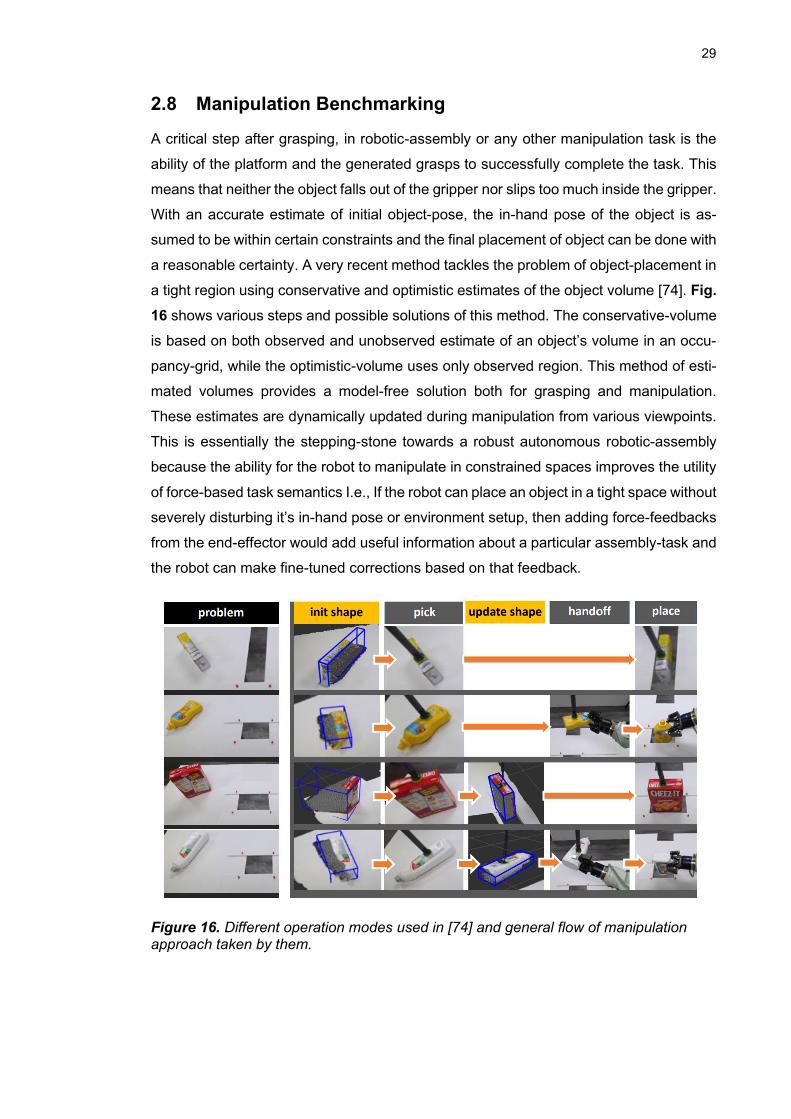
a reasonable certainty. A very recent method tackles the problem of object-placement in
a tight region using conservative and optimistic estimates of the object volume [74]. Fig.
16 shows various steps and possible solutions of this method. The conservative-volume
is based on both observed and unobserved estimate of an object’s volume in an occu-
pancy-grid, while the optimistic-volume uses only observed region. This method of esti-
mated volumes provides a model-free solution both for grasping and manipulation.
These estimates are dynamically updated during manipulation from various viewpoints.
This is essentially the stepping-stone towards a robust autonomous robotic-assembly
because the ability for the robot to manipulate in constrained spaces improves the utility
of force-based task semantics I.e., If the robot can place an object in a tight space without
severely disturbing it’s in-hand pose or environment setup, then adding force-feedbacks
from the end-effector would add useful information about a particular assembly-task and
the robot can make fine-tuned corrections based on that feedback.
Figure 16. Different operation modes used in [74] and general flow of manipulation approach taken by them.
30
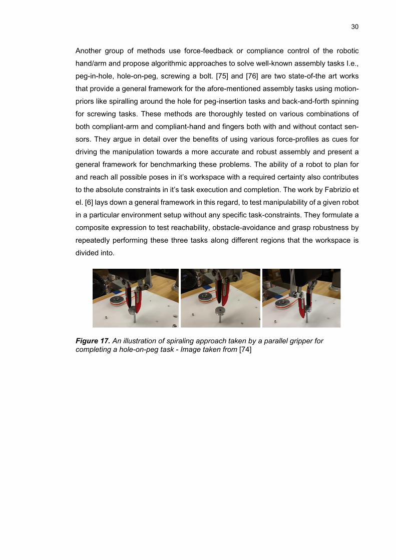
Another group of methods use force-feedback or compliance control of the robotic
hand/arm and propose algorithmic approaches to solve well-known assembly tasks I.e.,
peg-in-hole, hole-on-peg, screwing a bolt. [75] and [76] are two state-of-the art works
that provide a general framework for the afore-mentioned assembly tasks using motion-
priors like spiralling around the hole for peg-insertion tasks and back-and-forth spinning
for screwing tasks. These methods are thoroughly tested on various combinations of
both compliant-arm and compliant-hand and fingers both with and without contact sen-
sors. They argue in detail over the benefits of using various force-profiles as cues for
driving the manipulation towards a more accurate and robust assembly and present a
general framework for benchmarking these problems. The ability of a robot to plan for
and reach all possible poses in it’s workspace with a required certainty also contributes
to the absolute constraints in it’s task execution and completion. The work by Fabrizio et
el. [6] lays down a general framework in this regard, to test manipulability of a given robot
in a particular environment setup without any specific task-constraints. They formulate a
composite expression to test reachability, obstacle-avoidance and grasp robustness by
repeatedly performing these three tasks along different regions that the workspace is
divided into.
Figure 17. An illustration of spiraling approach taken by a parallel gripper for completing a hole-on-peg task - Image taken from [74]
31
3. IMPLEMENTATION
3.1 Multiclass pose-estimation
This section deals with 6DoF object-pose estimation on a custom dataset and describes
the architecture, data-collection and training of a keypoint-based deep-learning method
called PVN3d [57]. The particular choice of this method was due to the following factors:
• In the literature, voting-based methods were found to be more robust to clutter
and occlusions in general. Moreover, these methods are also light-weight in
computation, as they don’t need to process complex global or local descriptors
and the final pose-estimation is a coarse-coarse registration.
• Pixel-wise voting schemes are proved to be more robust to occlusions and gen-
eralize well to size, shape, texture and lighting [57] [37] [62].
• This particular method “PVN3d” provides an efficient joint-learning technique, in
which two parallel branches of the same network i.e., Semantic-segmentation
and Keypoint offset-estimation are jointly trained, which results in improved ac-
curacy in final pose estimate.
• A complete open-source repository, along with pre-trained models and evalua-
tion scripts are available at: https://github.com/ethnhe/PVN3D
3.1.1 OpenDR Dataset
This is a custom dataset of experimental nature. It comprises of a few commonly used
engine-assembly parts and a standard set of parts from the cranfield assembly [63].
These parts are chosen for their variety of shape, size, mass-distribution and manipula-
bility. It forms an initial step towards a rather wider dataset in future and provides enough
flexibility to test multiple use-cases with increasing levels of complexities for pose-esti-
mation, grasping and manipulation. A CAD-model image of all the objects used in this
dataset are shown in Fig 18.
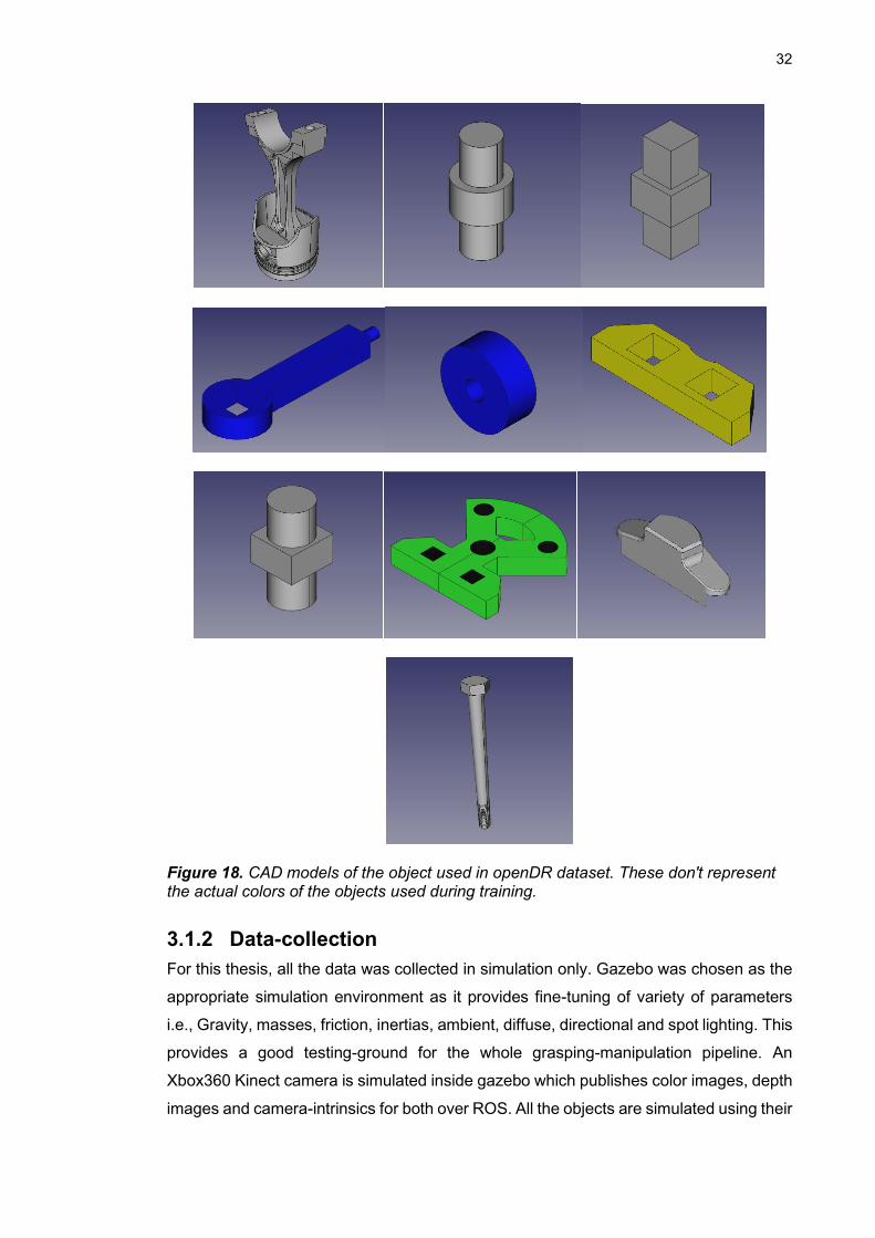
32
Figure 18. CAD models of the object used in openDR dataset. These don't represent the actual colors of the objects used during training.
3.1.2 Data-collection
For this thesis, all the data was collected in simulation only. Gazebo was chosen as the
appropriate simulation environment as it provides fine-tuning of variety of parameters
i.e., Gravity, masses, friction, inertias, ambient, diffuse, directional and spot lighting. This
provides a good testing-ground for the whole grasping-manipulation pipeline. An
Xbox360 Kinect camera is simulated inside gazebo which publishes color images, depth
images and camera-intrinsics for both over ROS. All the objects are simulated using their
33
standard polygon mesh files generated from CAD models. Only ambient and diffuse
lighting (i.e., no directional or spot light) is used with fixed color for each object. The
background is left out to be a brightly lit grey room with no walls and the objects always
resting on the floor in most stable equilibrium poses. For the sake of simplicity, no dense
background clutter or non-dataset objects are added to the environment. This is done
so, because the current simulation conditions don’t require the algorithm to deal with any
complex background objects other than the plane-grey simulation environment itself.
Since, the final evaluation is presented in the same simulation environment, this simpli-
fication was inevitable. Although the same environment could be enriched with a wide
variety of non-dataset gazebo objects and more data could collected following the same
scheme.
A moderately dense clutter of all the objects in the dataset is created (around the origin
in gazebo) with 3 distinct sets of relative positioning of objects with different levels of
clutter and truncation. A hemisphere-sampling as described in [32] is carried out around
each clutter-set. The steps in this sampling are briefly described as :
• The camera is moved from yaw=0 degrees to yaw=360 degrees in increments of
15 degrees around the clutter, with it’s principle-axis always pointing towards the
origin in gazebo.
• For each yaw the camera goes from a pitch=25 degrees to a pitch=85 degrees
in increments of 10 degrees, with it’s principle-axis always pointing towards the
origin in gazebo. This range allows for an adequate number of samples and
avoids sampling objects in nearly flat poses (either completely horizontal or ver-
tical with respect to the camera).
• For each of combination of yaws and pitches, a total of four different scales are
sampled i.e., Hemishperes of four different radii from 65cm to 95cm with incre-
ments of 10cm, are sampled around the gazebo origin.
A similar setup has been used for data-collection and mesh re-construction in both Line-
MOD[32] and YCB [33] datasets. Fig. 19 shows images from data-collection following
this scheme.
For each sample, the dataset records RGB and depth images of the scene, a grey-scale
image with binary mask of each object encoded with the respective class label and the
ground truth poses of each object in camera-coordinates, acquired directly from gazebo.
Also, since the simulation can directly query accurate camera-in-world pose for each
sample, there is no need for extrinsic camera-calibration. Given, the transformations
𝑇 𝑤𝑜𝑟𝑙𝑑
𝑐𝑎𝑚𝑒𝑟𝑎 and 𝑇 𝑤𝑜𝑟𝑙𝑑
𝑜𝑏𝑗𝑒𝑐𝑡, we can simply record ground truth poses as :

34
𝑇 𝐶𝑎𝑚𝑒𝑟𝑎
𝑜𝑏𝑗𝑒𝑐𝑡 = 𝑇 𝑤𝑜𝑟𝑙𝑑
𝑐𝑎𝑚𝑒𝑟𝑎−1
. 𝑇 𝑤𝑜𝑟𝑙𝑑
𝑜𝑏𝑗𝑒𝑐𝑡 (1)
Where T represents 4 x 4 transformation matrices describing the rotation and translation
of the target frame (in subscripts) in the source frame (in superscripts). For each object
mesh, greedy farthest-point-sampling is used to sample keypoints that spread-out at fur-
thest possible distances from each other on the mesh surface. Three different versions
i.e., 8, 12 and 16 keypoints are used for training three separate network checkpoints.
Figure 19. Upper hemisphere sampling for openDR data-collection. The images show camera sampling the scene at various poses all super imposed in one frame. For the sake of visibility, samples shown here are lesser than the actual number of samples used.
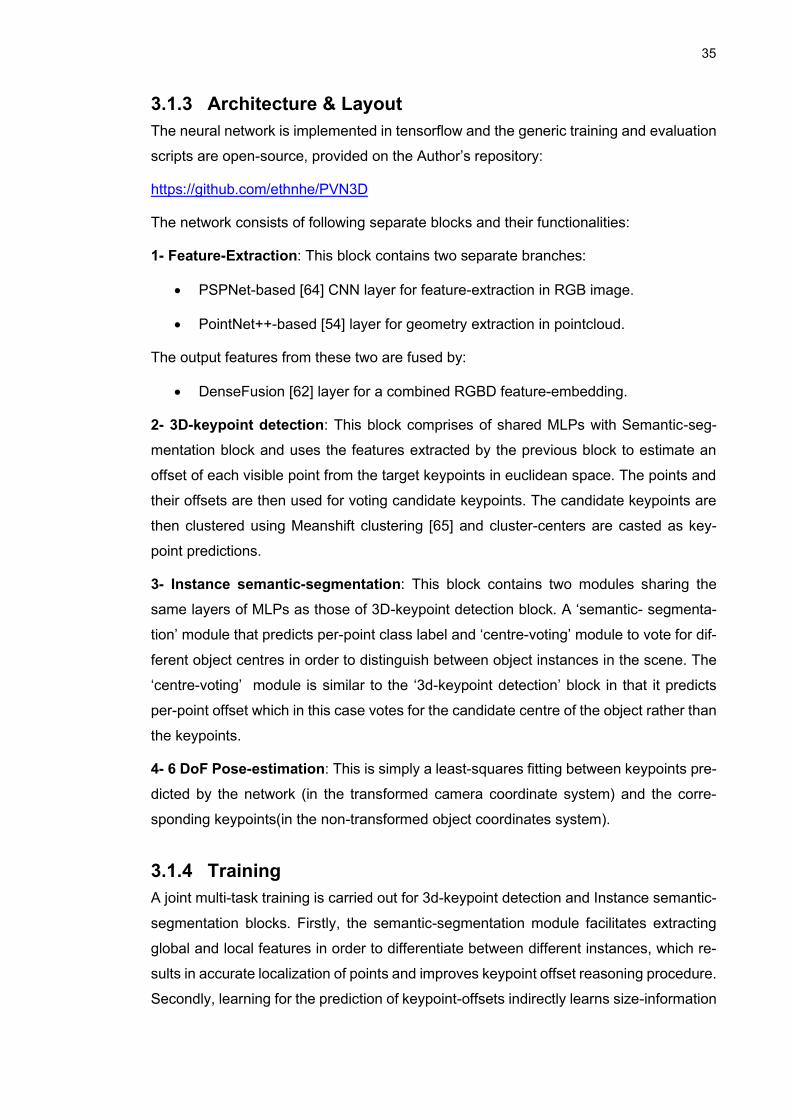
35
3.1.3 Architecture & Layout
The neural network is implemented in tensorflow and the generic training and evaluation
scripts are open-source, provided on the Author’s repository:
https://github.com/ethnhe/PVN3D
The network consists of following separate blocks and their functionalities:
1- Feature-Extraction: This block contains two separate branches:
• PSPNet-based [64] CNN layer for feature-extraction in RGB image.
• PointNet++-based [54] layer for geometry extraction in pointcloud.
The output features from these two are fused by:
• DenseFusion [62] layer for a combined RGBD feature-embedding.
2- 3D-keypoint detection: This block comprises of shared MLPs with Semantic-seg-
mentation block and uses the features extracted by the previous block to estimate an
offset of each visible point from the target keypoints in euclidean space. The points and
their offsets are then used for voting candidate keypoints. The candidate keypoints are
then clustered using Meanshift clustering [65] and cluster-centers are casted as key-
point predictions.
3- Instance semantic-segmentation: This block contains two modules sharing the
same layers of MLPs as those of 3D-keypoint detection block. A ‘semantic- segmenta-
tion’ module that predicts per-point class label and ‘centre-voting’ module to vote for dif-
ferent object centres in order to distinguish between object instances in the scene. The
‘centre-voting’ module is similar to the ‘3d-keypoint detection’ block in that it predicts
per-point offset which in this case votes for the candidate centre of the object rather than
the keypoints.
4- 6 DoF Pose-estimation: This is simply a least-squares fitting between keypoints pre-
dicted by the network (in the transformed camera coordinate system) and the corre-
sponding keypoints(in the non-transformed object coordinates system).
3.1.4 Training
A joint multi-task training is carried out for 3d-keypoint detection and Instance semantic-
segmentation blocks. Firstly, the semantic-segmentation module facilitates extracting
global and local features in order to differentiate between different instances, which re-
sults in accurate localization of points and improves keypoint offset reasoning procedure.
Secondly, learning for the prediction of keypoint-offsets indirectly learns size-information
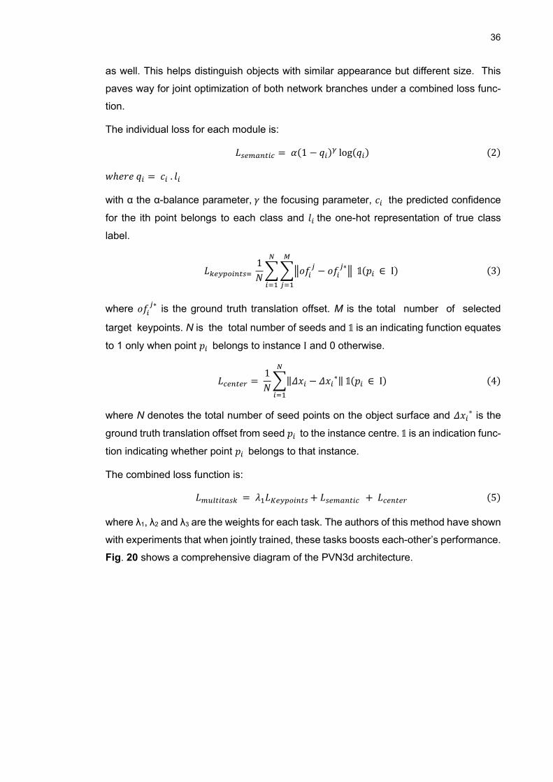
36
as well. This helps distinguish objects with similar appearance but different size. This
paves way for joint optimization of both network branches under a combined loss func-
tion.
The individual loss for each module is:
𝐿𝑠𝑒𝑚𝑎𝑛𝑡𝑖𝑐 = 𝛼(1 − 𝑞𝑖)𝛾 log(𝑞𝑖) (2)
𝑤ℎ𝑒𝑟𝑒 𝑞𝑖 = 𝑐𝑖 . 𝑙𝑖
with α the α-balance parameter, 𝛾 the focusing parameter, 𝑐𝑖 the predicted confidence
for the ith point belongs to each class and 𝑙𝑖 the one-hot representation of true class
label.
𝐿𝑘𝑒𝑦𝑝𝑜𝑖𝑛𝑡𝑠=
1
𝑁∑ ∑‖𝑜𝑓𝑖
𝑗− 𝑜𝑓𝑖
𝑗∗‖ 𝟙(𝑝𝑖 ∈ I)
𝑀
𝑗=1
𝑁
𝑖=1
(3)
where 𝑜𝑓𝑖𝑗∗
is the ground truth translation offset. M is the total number of selected
target keypoints. N is the total number of seeds and 𝟙 is an indicating function equates
to 1 only when point 𝑝𝑖 belongs to instance I and 0 otherwise.
𝐿𝑐𝑒𝑛𝑡𝑒𝑟 = 1
𝑁∑‖𝛥𝑥𝑖 − 𝛥𝑥𝑖
∗‖ 𝟙(𝑝𝑖 ∈ I)
𝑁
𝑖=1
(4)
where N denotes the total number of seed points on the object surface and 𝛥𝑥𝑖∗ is the
ground truth translation offset from seed 𝑝𝑖 to the instance centre. 𝟙 is an indication func-
tion indicating whether point 𝑝𝑖 belongs to that instance.
The combined loss function is:
𝐿𝑚𝑢𝑙𝑡𝑖𝑡𝑎𝑠𝑘 = 𝜆1𝐿𝐾𝑒𝑦𝑝𝑜𝑖𝑛𝑡𝑠 + 𝐿𝑠𝑒𝑚𝑎𝑛𝑡𝑖𝑐 + 𝐿𝑐𝑒𝑛𝑡𝑒𝑟 (5)
where λ1, λ2 and λ3 are the weights for each task. The authors of this method have shown
with experiments that when jointly trained, these tasks boosts each-other’s performance.
Fig. 20 shows a comprehensive diagram of the PVN3d architecture.
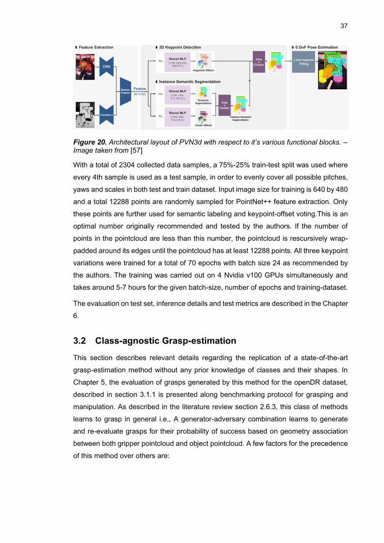
37
Figure 20. Architectural layout of PVN3d with respect to it’s various functional blocks. – Image taken from [57]
With a total of 2304 collected data samples, a 75%-25% train-test split was used where
every 4th sample is used as a test sample, in order to evenly cover all possible pitches,
yaws and scales in both test and train dataset. Input image size for training is 640 by 480
and a total 12288 points are randomly sampled for PointNet++ feature extraction. Only
these points are further used for semantic labeling and keypoint-offset voting.This is an
optimal number originally recommended and tested by the authors. If the number of
points in the pointcloud are less than this number, the pointcloud is rescursively wrap-
padded around its edges until the pointcloud has at least 12288 points. All three keypoint
variations were trained for a total of 70 epochs with batch size 24 as recommended by
the authors. The training was carried out on 4 Nvidia v100 GPUs simultaneously and
takes around 5-7 hours for the given batch-size, number of epochs and training-dataset.
The evaluation on test set, inference details and test metrics are described in the Chapter
6.
3.2 Class-agnostic Grasp-estimation
This section describes relevant details regarding the replication of a state-of-the-art
grasp-estimation method without any prior knowledge of classes and their shapes. In
Chapter 5, the evaluation of grasps generated by this method for the openDR dataset,
described in section 3.1.1 is presented along benchmarking protocol for grasping and
manipulation. As described in the literature review section 2.6.3, this class of methods
learns to grasp in general i.e., A generator-adversary combination learns to generate
and re-evaluate grasps for their probability of success based on geometry association
between both gripper pointcloud and object pointcloud. A few factors for the precedence
of this method over others are:
38
• Compared to other methods [42], [15] and [16], this method provides a much
better coverage of grasp-space and learns to predict grasps that are more diverse
along the object geometry.
• Additionally, this method provides refinement of near-failure grasps which makes
up for the number of rejected grasps and gives it a higher recall than other meth-
ods.
• The grasp-quality labelling is more discretized and mapped along a gaussian as
compared to other methods that either use binary (success or failure labels)[42],
[15] or use very few discrete quality labels [16]. This results in a drastically im-
proved grasp quality evaluation as compared in the original paper [17]
• The authors of this method report an overall improvement in success-rate of
grasps as the grasps are dense and diverse. Even with high number of failed
grasps, there is still a considerably higher proportion of successful grasps.
• The dataset this method is trained on, has a much higher number of sampled
grasps, simulated on a much wider category of objects than other methods. This
is discussed further in section 3.2.3.
3.2.1 Architecture & Layout
As mentioned in the literature review this method has two main components and a third
refinement step:
Grasp-Sampler: This part is a Variational Auto-encoder [66] that are widely used as
generative models in other machine learning domains and can undergo unsupervised
training to maximize likelihood of the training data. In this method, a VAE with PointNet++
encoding layers, learns to maximize the likelihood P(G|X) of ground-truth positive grasps
G given a pointcloud X. G and X are mapped to latent-space variable z. The probability
density function P(z) in latent space is approximated to be uniform hence, the likelihood
of the generated grasps can be written as follows:
𝑃(𝐺 |𝑋, 𝑧; 𝜃)𝑃(𝑧)𝑑𝑧 (6)
This is achieved through a combination of encoder and decoder during training shown in
Fig. 21.
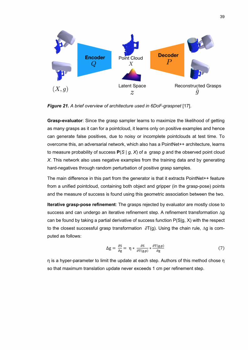
39
Figure 21. A brief overview of architecture used in 6DoF-graspnet [17].
Grasp-evaluator: Since the grasp sampler learns to maximize the likelihood of getting
as many grasps as it can for a pointcloud, it learns only on positive examples and hence
can generate false positives, due to noisy or incomplete pointclouds at test time. To
overcome this, an adversarial network, which also has a PointNet++ architecture, learns
to measure probability of success P(S | g, X) of a grasp g and the observed point cloud
X. This network also uses negative examples from the training data and by generating
hard-negatives through random perturbation of positive grasp samples.
The main difference in this part from the generator is that it extracts PointNet++ feature
from a unified pointcloud, containing both object and gripper (in the grasp-pose) points
and the measure of success is found using this geometric association between the two.
Iterative grasp-pose refinement: The grasps rejected by evaluator are mostly close to
success and can undergo an iterative refinement step. A refinement transformation ∆g
can be found by taking a partial derivative of success function P(S|g, X) with the respect
to the closest successful grasp transformation ∂T(g). Using the chain rule, ∆g is com-
puted as follows:
∆g = ∂S
∂g= η ∗
∂S
∂T(g,p)∗
∂T(g,p)
∂g (7)
η is a hyper-parameter to limit the update at each step. Authors of this method chose η
so that maximum translation update never exceeds 1 cm per refinement step.
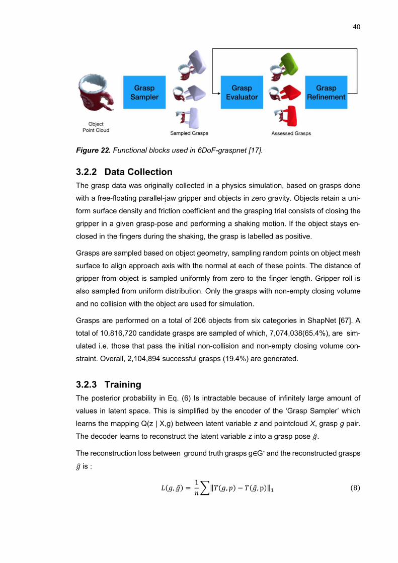
40
Figure 22. Functional blocks used in 6DoF-graspnet [17].
3.2.2 Data Collection
The grasp data was originally collected in a physics simulation, based on grasps done
with a free-floating parallel-jaw gripper and objects in zero gravity. Objects retain a uni-
form surface density and friction coefficient and the grasping trial consists of closing the
gripper in a given grasp-pose and performing a shaking motion. If the object stays en-
closed in the fingers during the shaking, the grasp is labelled as positive.
Grasps are sampled based on object geometry, sampling random points on object mesh
surface to align approach axis with the normal at each of these points. The distance of
gripper from object is sampled uniformly from zero to the finger length. Gripper roll is
also sampled from uniform distribution. Only the grasps with non-empty closing volume
and no collision with the object are used for simulation.
Grasps are performed on a total of 206 objects from six categories in ShapNet [67]. A
total of 10,816,720 candidate grasps are sampled of which, 7,074,038(65.4%), are sim-
ulated i.e. those that pass the initial non-collision and non-empty closing volume con-
straint. Overall, 2,104,894 successful grasps (19.4%) are generated.
3.2.3 Training
The posterior probability in Eq. (6) Is intractable because of infinitely large amount of
values in latent space. This is simplified by the encoder of the ‘Grasp Sampler’ which
learns the mapping Q(z | X,g) between latent variable z and pointcloud X, grasp g pair.
The decoder learns to reconstruct the latent variable z into a grasp pose 𝑔.
The reconstruction loss between ground truth grasps g∈G* and the reconstructed grasps
𝑔 is :
𝐿(𝑔, 𝑔) = 1
𝑛∑‖𝑇(𝑔, 𝑝) − 𝑇(𝑔, p)‖1 (8)
41
here 𝑇(−, 𝑝) is the transformation of a set of predefined points p on the robot gripper
The total Loss function learned by VAE is
𝐿𝑣𝑎𝑒 = ∑ 𝐿(𝑔, 𝑔) − 𝛼𝐷𝐾𝐿[ 𝑄(𝑧 |X, g ), 𝑵(0, 𝐼)]
𝑧~𝑄, 𝑔~𝐺∗
(9)
where 𝐷𝐾𝐿 represents a KL-divergence between the complex distribution Q(·|·) and the
normal distribution 𝑵(0, 𝐼), which is also a part of minimization in order to ensure a normal
distribution in latent space with unit variance. For pointcloud X, grasps g are sampled
from the set of ground truth grasps G* using stratified sampling. Both encoder and de-
coder are PointNet++ based and encode a feature vector that has 3D coordinates of the
sampled point and and relative position of it’s neighbours. The decoder concatenates
latent variable z with this feature vector. Optimizing the loss function in Eq. using sto-
chastic gradient descent makes encoder learn to pack enough information (about grasp
and the pointcloud ) in variable z so that the decoder can reliably reconstruct the grasps
with this variable.
The grasp evaluator is optimized using the cross-entropy loss:
𝐿𝑒𝑣𝑎𝑙𝑢𝑎𝑡𝑜𝑟 = −(𝑦𝑙𝑜𝑔(𝑠) + (1 − 𝑦) log(1 − 𝑠)) (10)
where y is the ground truth binary label of the grasps indicating whether the grasp is
successful or not and s is the predicted probability of success by the evaluator.
The evaluation of grasps generated on openDR dataset, success metrics and inference
details for this method are discussed in Chapter 5.
3.3 Simulating Grasps
Grasps are simulated on a Franka Emika Panda robot, simulated in Gazebo using
MoveIt ROS library and ros_control [68]. The ros_control provides a generic and robot-
agnostic framework to interface any real or simulated robot with 3rd - party clients in
ROS that handle manipulation-planning e.g. MoveIt or path-planning e.g. ROS naviga-
tion stack. It provides a set of hardware abstraction classes that expose general-pur-
pose hardware components i.e., Hydraulic and electric actuators or encoders and
force/torque sensors using general-purpose controllers i.e., Effort controllers, joint-state
controllers, position controllers, velocity controllers, joint-trajectory controllers. It pro-
vides a very modular interface which makes minimal assumption about hardware and
can easily be adapted to any robot. It implements life-cycle management of controllers
and resource management of hardware in order to guarantee real-time control. Fig. 23
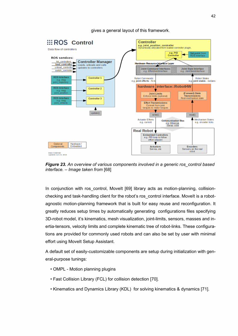
42
gives a general layout of this framework.
Figure 23. An overview of various components involved in a generic ros_control based interface. – Image taken from [68]
In conjunction with ros_control, MoveIt [69] library acts as motion-planning, collision-
checking and task-handling client for the robot’s ros_control interface. MoveIt is a robot-
agnostic motion-planning framework that is built for easy reuse and reconfiguration. It
greatly reduces setup times by automatically generating configurations files specifying
3D-robot model, it’s kinematics, mesh visualization, joint-limits, sensors, masses and in-
ertia-tensors, velocity limits and complete kinematic tree of robot-links. These configura-
tions are provided for commonly used robots and can also be set by user with minimal
effort using MoveIt Setup Assistant.
A default set of easily-customizable components are setup during initialization with gen-
eral-purpose tunings:
• OMPL - Motion planning plugins
• Fast Collision Library (FCL) for collision detection [70].
• Kinematics and Dynamics Library (KDL) for solving kinematics & dynamics [71].

43
The library also provides real-time visualization of the motion-plans, paths, trajectories
and generated torques. A set of C++ and python-based APIs provide high-level tools for
exploiting the underlying functionality.
3.3.1 Robot setup in Gazebo
For setting up the robot’s joint-actuation, control and joint-state polling in Gazebo physics
simulator, a minimal set of changes are followed from the blog post in [72]:
• Each joint is given damping coefficient for dynamics simulation.
• Each link is assigned inertia matrix, calculated using simple geometrical analysis
of it’s mesh file.
• Each link is assigned a mass estimated from it’s volume (calculated by mesh
analysis) and density assumed to be of the material ‘Aluminium mild’, which is
the closest to that of actual material used.
• Each link is assigned a friction coefficient of 0.61 of the material ‘Aluminium mild’.
• A new joint-transmission configuration is added to Franka_ros package which
uses gazebo_ros_control plugin to activate joint-control and actuation in simula-
tion.
• MoveIt controller configuration is changed to used follow_joint_trajectory which
the kind of controller simulated by Gazebo.
Franka_ros package provides an analogous of ros_control package which inherits from
standard hardware_interface and controller classes and defines it’s own version of hard-
ware interfaces as franka_hw classes and controller nodes in franka_control sub-pack-
age. It lays out its own framework to ease integration between ros_control and Franka
Control Interface (FCI), a fast and direct low-level bidirectional connection on the robot.
A general layout of integration between gazebo simulated hardware interface and
franka_ros is shown in Fig. 24.
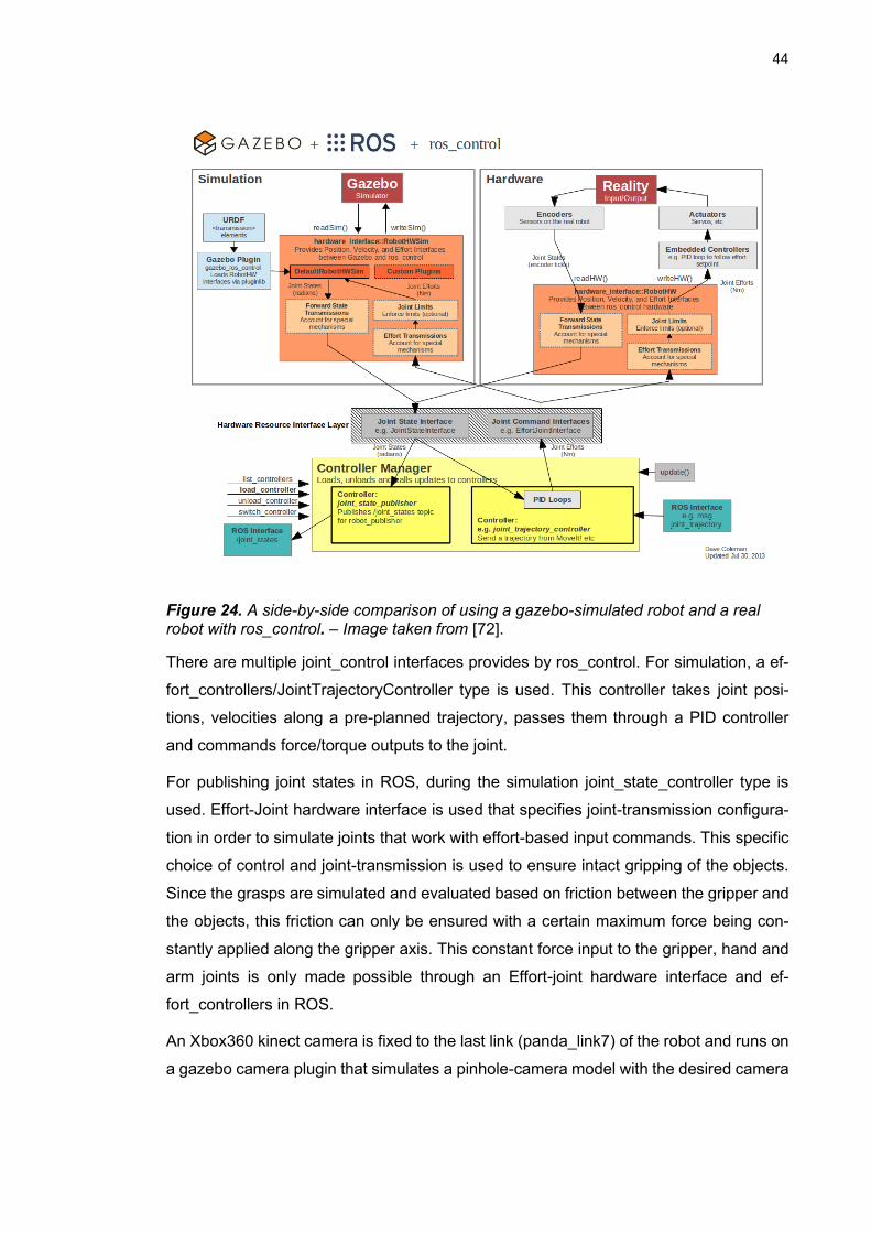
44
Figure 24. A side-by-side comparison of using a gazebo-simulated robot and a real robot with ros_control. – Image taken from [72].
There are multiple joint_control interfaces provides by ros_control. For simulation, a ef-
fort_controllers/JointTrajectoryController type is used. This controller takes joint posi-
tions, velocities along a pre-planned trajectory, passes them through a PID controller
and commands force/torque outputs to the joint.
For publishing joint states in ROS, during the simulation joint_state_controller type is
used. Effort-Joint hardware interface is used that specifies joint-transmission configura-
tion in order to simulate joints that work with effort-based input commands. This specific
choice of control and joint-transmission is used to ensure intact gripping of the objects.
Since the grasps are simulated and evaluated based on friction between the gripper and
the objects, this friction can only be ensured with a certain maximum force being con-
stantly applied along the gripper axis. This constant force input to the gripper, hand and
arm joints is only made possible through an Effort-joint hardware interface and ef-
fort_controllers in ROS.
An Xbox360 kinect camera is fixed to the last link (panda_link7) of the robot and runs on
a gazebo camera plugin that simulates a pinhole-camera model with the desired camera
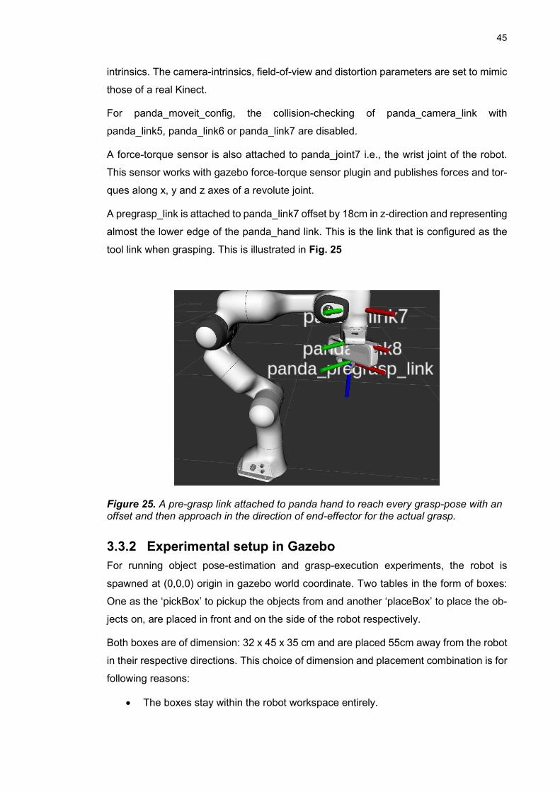
45
intrinsics. The camera-intrinsics, field-of-view and distortion parameters are set to mimic
those of a real Kinect.
For panda_moveit_config, the collision-checking of panda_camera_link with
panda_link5, panda_link6 or panda_link7 are disabled.
A force-torque sensor is also attached to panda_joint7 i.e., the wrist joint of the robot.
This sensor works with gazebo force-torque sensor plugin and publishes forces and tor-
ques along x, y and z axes of a revolute joint.
A pregrasp_link is attached to panda_link7 offset by 18cm in z-direction and representing
almost the lower edge of the panda_hand link. This is the link that is configured as the
tool link when grasping. This is illustrated in Fig. 25
Figure 25. A pre-grasp link attached to panda hand to reach every grasp-pose with an offset and then approach in the direction of end-effector for the actual grasp.
3.3.2 Experimental setup in Gazebo
For running object pose-estimation and grasp-execution experiments, the robot is
spawned at (0,0,0) origin in gazebo world coordinate. Two tables in the form of boxes:
One as the ‘pickBox’ to pickup the objects from and another ‘placeBox’ to place the ob-
jects on, are placed in front and on the side of the robot respectively.
Both boxes are of dimension: 32 x 45 x 35 cm and are placed 55cm away from the robot
in their respective directions. This choice of dimension and placement combination is for
following reasons:
• The boxes stay within the robot workspace entirely.

46
• The boxes stay within the field-of-view of the camera-on-robot entirely.
• The robot has enough space in front of it so as to not be tightly constrained by
the boxes during grasp-planning.
• The camera stays at least 50cm away from the table-top and tilted towards it
between 30 – 45 degrees of range. For the given object-set, these viewpoints
provide a good visibility of geometry for both objects that lie flat (principle axis
parallel to the ground) and objects that stand upright(principle axis perpendicular
to the ground).
• The ‘home’ position of the robot joints can be defined, so that the condition 3 is
met and only the top-face of table is visible, in order to prevent any false detec-
tions.
• The ‘home’ position can be defined so that it easily is achievable after every
grasp-place cycle, with very low joint displacements from grasp or place posi-
tions.
All the objects are directly imported in gazebo from their mesh files and are assigned
approximate inertia-tensors based on a closely-related shape i.e., Cube, cylinder, hol-
low-cylinder, rod etc. These shape-approximation along with the masses assigned to
each object are provided in Table. All the objects are assigned a co-efficient of friction
1.15 i.e., that of rubber on a rubber referred from https://www.engineersedge.com/coef-
fients_of_friction.html .
This is to keep a maximum possible friction during experiments, in order to deal with
limitations and instability of simulation and still being relatively close to reality as it is
possible to have the objects in this dataset to be of rubber and so do the gripper.
Objects are placed in their stable equilibrium pick-poses chosen based on their required
final placement-poses. Following are three kinds of objects based on their placement
poses:
I. Stable Upright Pose: This includes square and round pegs, shaft and piston.
These objects are to be placed upright hence, their picking-poses are so that their
principle-axis is perpendicular to the ground
II. Stable Lying-flat pose: This includes all other objects that can only lie flat, with
their principle-axis parallel to the ground in order to be stable. They also need to
be placed in flat-poses.
47
III. Marginally stable pose: The only object in this category is the pendulum-head.
It is deliberately kept in a semi-stable upright pose in order to keep it graspable.
If instead it lies flat, in a stable pose, the only way is to grasp it, is along its rim.
For its small dimensions, grasping along the rim either fails because of being too
close to the ground or because of an unstable twist produced along the axis of
this object with this kind of grasp.
The same poses described here are the ones that Pose-detection method in section 3.1
is trained on. The following discussion on grasp-manipulation experiments and their re-
sults is only carried out on 6 out of 10 objects that the pose-estimation algorithm was
trained on. This includes the following in the order of their class labels:
1- Piston
2- Round peg
3- Square Peg
4- Pendulum
6- Separator
7- Shaft
Other objects are excluded because they are highly likely to fail for most grasps for the
following reasons:
5- Pendulum head (very low in height and is only semi-stable when grasped or placed)
8- Faceplate (has no dimension small enough to fit in the gripper)
9- Valve Tappet (very low in height)
10- M11-50mm Shoulder bolt (very low in height)
48
4. EXPERIMENTS
For the experimental setup described in section 3.3.2, two different classes of experi-
mental schemes are carried out for the evaluation of grasp-manipulate pipeline:
4.1 Pick-and-Place:
This experiment scheme is used with pose-aware grasping i.e., when the object-poses
are estimated using method described in section 3.1 and grasps are predefined in object
coordinates. Due to information about object’s pose and grasps defined with respect to
this pose, accurate final placement of the object can be easily evaluated and hence
placement is the method employed in this scheme for testing the grasps utility.
1. Objects are spawned both in isolation and in clutter on the ‘pickBox’.
2. The robot goes to it’s ‘Home’ position and runs pose-estimation on a single frame
of the ‘pickBox’.
3. Grasp-poses predefined in object coordinates are loaded for object/objects in
the scene and transferred to gazebo world coordinate system.
4. Both the pick and place boxes are added to the MoveIt planning scene along
with an octomap of the objects in the scene, in order to plan collision-free path
towards the grasp pose.
5. In the case of clutter, object closest to the camera is grasped first.
6. If path to the grasp-pose is planned and it is reached successfully, the octomap
and boxes are removed from the planning scene and the robot moves 3cm for-
ward in the approach direction. All the predefined grasps are calculated based
on this 3cm offset, with the lower edge of the gripper barely touching the object
after approach motion is executed.
7. The gripper is fully closed, to apply a maximum force on the object and retreats
backward in the approach direction. It then waits for about 3 seconds and checks
if the gripper has fully closed or not. If yes, than the object has fallen out of the
gripper and the grasp has failed. Then the robot moves onto the next available
grasp and repeats from step 2.
8. If the grasp-test was passed in the previous step, the robot moves onto a prede-
fined joint configuration over the ‘placeBox’ called the pre-place position. This
49
configuration is closer to the placement poses and hence planning is easier. The
boxes are added once again to the planning scene, in order to avoid colliding
during motion for placement.
9. The robot moves few centi-meters above a certain pose predefined in word co-
ordinates over the ‘placeBox’. The choice of both pick and place poses is ex-
plained in section 4.5
10. With the grasps defined in object-coordinates, the translation offset of gripper in
X and Y direction and rotation offset along gripper’s approach axis (yaw) from
object’s fixed frame can be easily calculated and is used to properly align the
object over the place pose.
11. After alignment, the robot moves downward (in absolute coordinates) for the
touch-down and actively listens on the force-torque sensor topic. A predefined
force threshold in z-axis/y-axis (depending upon the hand’s tilt) tells whether the
object has touched the table surface.
12. With the object touched down the robot retreats upward a few milli-meters to
loosen the downward force and fully opens the gripper.
13. Results from the placement are finally stored in the form of differences between
desired and achieved x, y positions and yaw of the placed object. These are
summarized in Chapter 6.
14. The objects are re-spawned in their initial locations and robot moves to repeat
the same cycle of steps on the next grasp for the same object or for next closest
object.
4.2 Pick-and-Oscillate
This experiment scheme is used for the grasp-estimation method described in section
3.2 because there is no prior information of the object pose and hence accurate final
placement is not possible. The only way to test the grasp’s usefulness is then to test if
the object falls out of the gripper or not, when subject to a predefined jerky motion along
various axes. The steps in this scheme can be outlined as follows:
1. Objects are spawned only in clutter on the ‘pickBox’. These experiments are only
performed in clutter as there is no pose-estimation involved and the algorithm
divides each object into several pointcloud clusters (as long as the clutter is not
too close). The closest clutter is picked up first. This clutter-clearing strategy ef-
fectively removes the need to test in isolation.
50
2. The robot goes to it’s ‘Home’ position and takes a single pointcloud frame of the
scene and divides it into clusters based on euclidean distances of every point
from different cluster means.
3. A grasp-regression inference described in section 3.2 is then run on the cluster
closest to the camera and grasps are arranged from highest to the lowest grasp-
scores predicted by the network.
4. The generated grasps are on all sides of the pointcloud and in all directions, so
most of them are bound to fail. Hence, the grasps generated initially are filtered
to fit the following two constraints
a. All the grasps should be on the object-side facing the camera and should
always be facing away from the camera. Sideways grasps are also al-
lowed.
b. The grasps should never be tilted upwards more than 45 degrees.
Since euler-convention of the grasps are unknown and transformation
matrix doesn’t simply return the independent roll, pitch and yaw of the
grasp pose, this constraining problem is not very straightforward and is
extrapolated using projections of grasps on various planes. This is ex-
plained in detail in section 4.4.
5. The filtered grasps are then planned and executed in the decreasing order of
their scores. As in section 4.1, boxes and object octomap is added to the planning
scene in order to plan collision-free path.
6. After, planning, executing and approaching for grasp, the gripper is fully closed
and then retreats and waits for three seconds, to check if the gripper still has the
object in it.
7. After passing initial grasp-test, the robot performs a jerky oscillatory motion with
following trajectory points:
a. +/- 45 degrees along z-axis
b. +/- 45 degrees along x-axis
c. +/- 45 degrees along y-axis
After this motion is completed and robot comes to a stop, the gripper is again checked if
it still has the object in it. All the grasps for a single cluster are evaluated this way, rec-
orded as a binary success measure and the results are finally compiled for success rate
per object-category, summarized in Chapter 5.
51
8. The objects are re-spawned in their initial locations and robot moves to repeat
the same cycle of steps on the next closest object.
4.3 Pre-defined grasps
The pre-defined grasp poses mentioned in section 4.1 are neither sampled exhaustively
(across surface normals) nor uniformly across the object geometry. Instead following
criteria are used for defining only a few grasps in object coordinates.
• All the grasps should be at least 3 cm above the ground, since they will surely
fail below this threshold.
• For the objects lying flat, only top-down grasps are defined. These grasps are
defined along length of the object with 1 cm increments such that they are never
more than 3 cm ahead or behind the object’s center. This constraint is applied
so that object is never grasped too far from it’s center of mass and hence the in-
hand rotation is not excessive.
• For the objects standing upright, lateral-grasps (parallel to ground) are defined
along object height, always above the center-of-mass and facing directly away
from the camera 90 degrees along object surface. The transverse-grasps (per-
pendicular to ground) are defined to be always facing the ground and defined
with two possible configuration, i.e., with zero gripper yaw and 90 degrees yaw.
All other yaw values are redundant and hence left out.
These grasps for the all the object categories are shown in Fig. 26.
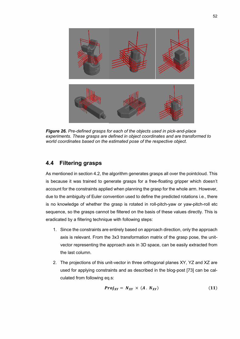
52
Figure 26. Pre-defined grasps for each of the objects used in pick-and-place experiments. These grasps are defined in object coordinates and are transformed to world coordinates based on the estimated pose of the respective object.
4.4 Filtering grasps
As mentioned in section 4.2, the algorithm generates grasps all over the pointcloud. This
is because it was trained to generate grasps for a free-floating gripper which doesn’t
account for the constraints applied when planning the grasp for the whole arm. However,
due to the ambiguity of Euler convention used to define the predicted rotations i.e., there
is no knowledge of whether the grasp is rotated in roll-pitch-yaw or yaw-pitch-roll etc
sequence, so the grasps cannot be filtered on the basis of these values directly. This is
eradicated by a filtering technique with following steps:
1. Since the constraints are entirely based on approach direction, only the approach
axis is relevant. From the 3x3 transformation matrix of the grasp pose, the unit-
vector representing the approach axis in 3D space, can be easily extracted from
the last column.
2. The projections of this unit-vector in three orthogonal planes XY, YZ and XZ are
used for applying constraints and as described in the blog-post [73] can be cal-
culated from following eq.s:
𝑷𝒓𝒐𝒋𝑿𝒀 = 𝑵𝑿𝒀 × (𝑨 . 𝑵𝑿𝒀) (𝟏𝟏)
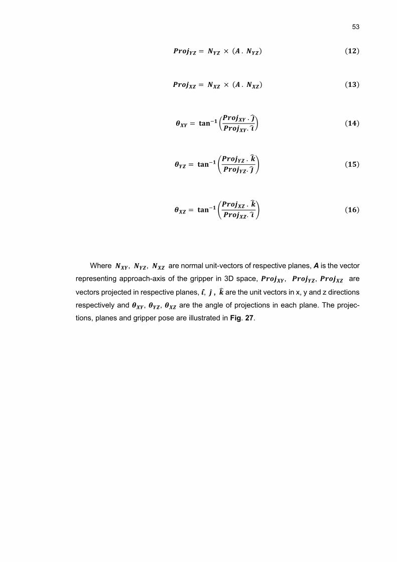
53
𝑷𝒓𝒐𝒋𝒀𝒁 = 𝑵𝒀𝒁 × (𝑨 . 𝑵𝒀𝒁) (𝟏𝟐)
𝑷𝒓𝒐𝒋𝑿𝒁 = 𝑵𝑿𝒁 × (𝑨 . 𝑵𝑿𝒁) (𝟏𝟑)
𝜽𝑿𝒀 = 𝐭𝐚𝐧−𝟏 (𝑷𝒓𝒐𝒋𝑿𝒀 . �̂�
𝑷𝒓𝒐𝒋𝑿𝒀. �̂�) (𝟏𝟒)
𝜽𝒀𝒁 = 𝐭𝐚𝐧−𝟏 (𝑷𝒓𝒐𝒋𝒀𝒁 . �̂�
𝑷𝒓𝒐𝒋𝒀𝒁. �̂�) (𝟏𝟓)
𝜽𝑿𝒁 = 𝐭𝐚𝐧−𝟏 (𝑷𝒓𝒐𝒋𝑿𝒁 . �̂�
𝑷𝒓𝒐𝒋𝑿𝒁. �̂�) (𝟏𝟔)
Where 𝑵𝑿𝒀, 𝑵𝒀𝒁, 𝑵𝑿𝒁 are normal unit-vectors of respective planes, A is the vector
representing approach-axis of the gripper in 3D space, 𝑷𝒓𝒐𝒋𝑿𝒀, 𝑷𝒓𝒐𝒋𝒀𝒁, 𝑷𝒓𝒐𝒋𝑿𝒁 are
vectors projected in respective planes, �̂�, 𝒋̂ , �̂� are the unit vectors in x, y and z directions
respectively and 𝜽𝑿𝒀, 𝜽𝒀𝒁, 𝜽𝑿𝒁 are the angle of projections in each plane. The projec-
tions, planes and gripper pose are illustrated in Fig. 27.
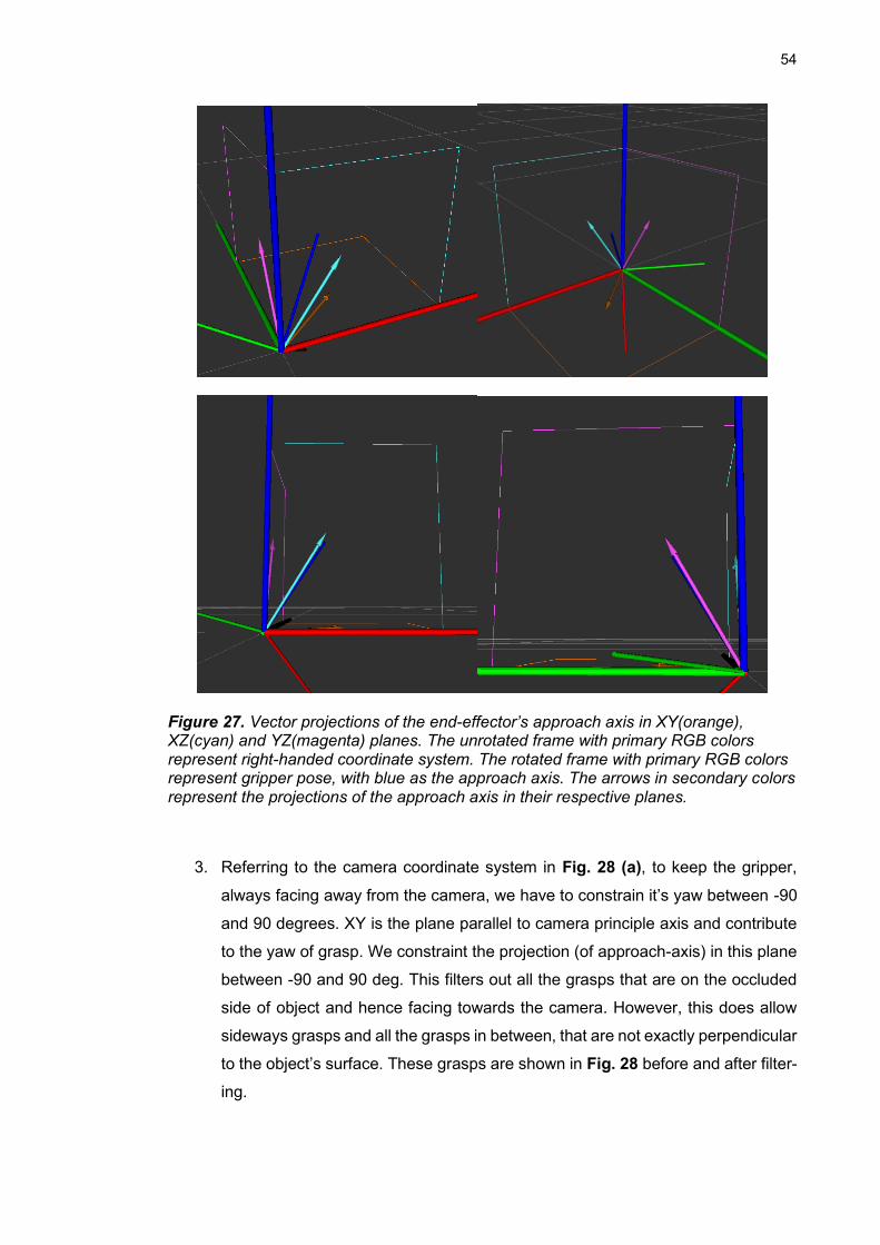
54
Figure 27. Vector projections of the end-effector’s approach axis in XY(orange), XZ(cyan) and YZ(magenta) planes. The unrotated frame with primary RGB colors represent right-handed coordinate system. The rotated frame with primary RGB colors represent gripper pose, with blue as the approach axis. The arrows in secondary colors represent the projections of the approach axis in their respective planes.
3. Referring to the camera coordinate system in Fig. 28 (a), to keep the gripper,
always facing away from the camera, we have to constrain it’s yaw between -90
and 90 degrees. XY is the plane parallel to camera principle axis and contribute
to the yaw of grasp. We constraint the projection (of approach-axis) in this plane
between -90 and 90 deg. This filters out all the grasps that are on the occluded
side of object and hence facing towards the camera. However, this does allow
sideways grasps and all the grasps in between, that are not exactly perpendicular
to the object’s surface. These grasps are shown in Fig. 28 before and after filter-
ing.
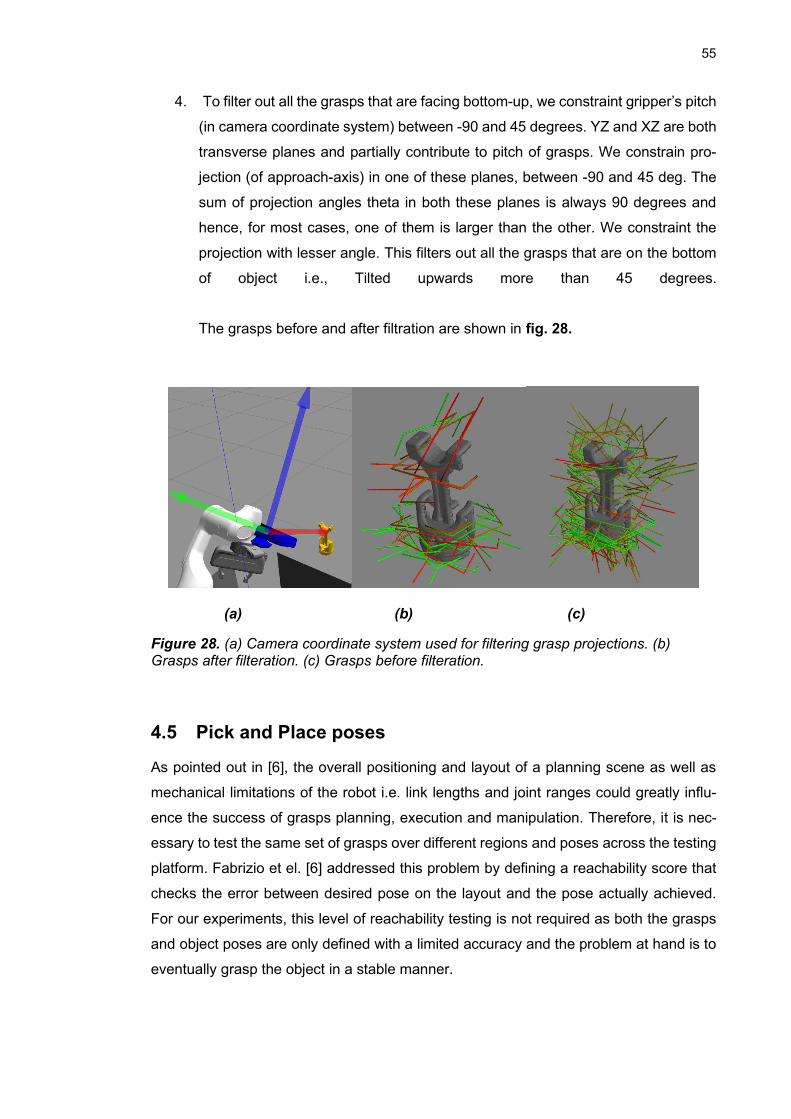
55
4. To filter out all the grasps that are facing bottom-up, we constraint gripper’s pitch
(in camera coordinate system) between -90 and 45 degrees. YZ and XZ are both
transverse planes and partially contribute to pitch of grasps. We constrain pro-
jection (of approach-axis) in one of these planes, between -90 and 45 deg. The
sum of projection angles theta in both these planes is always 90 degrees and
hence, for most cases, one of them is larger than the other. We constraint the
projection with lesser angle. This filters out all the grasps that are on the bottom
of object i.e., Tilted upwards more than 45 degrees.
The grasps before and after filtration are shown in fig. 28.
(a) (b) (c)
Figure 28. (a) Camera coordinate system used for filtering grasp projections. (b) Grasps after filteration. (c) Grasps before filteration.
4.5 Pick and Place poses
As pointed out in [6], the overall positioning and layout of a planning scene as well as
mechanical limitations of the robot i.e. link lengths and joint ranges could greatly influ-
ence the success of grasps planning, execution and manipulation. Therefore, it is nec-
essary to test the same set of grasps over different regions and poses across the testing
platform. Fabrizio et el. [6] addressed this problem by defining a reachability score that
checks the error between desired pose on the layout and the pose actually achieved.
For our experiments, this level of reachability testing is not required as both the grasps
and object poses are only defined with a limited accuracy and the problem at hand is to
eventually grasp the object in a stable manner.
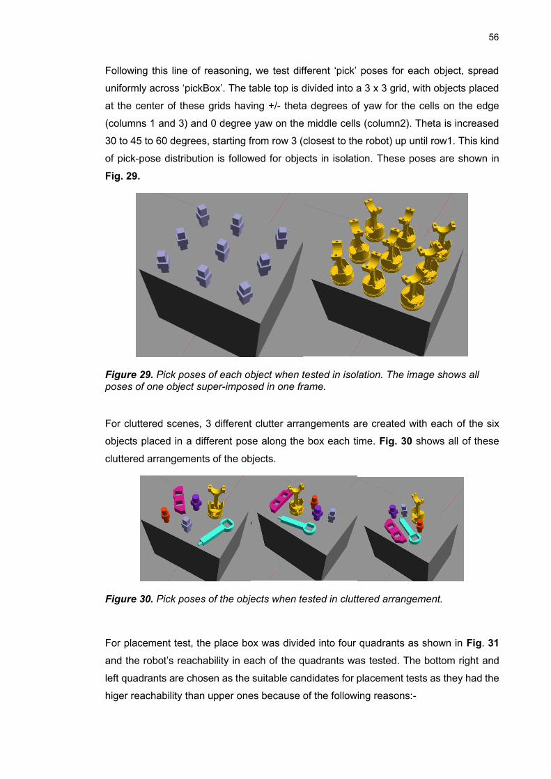
56
Following this line of reasoning, we test different ‘pick’ poses for each object, spread
uniformly across ‘pickBox’. The table top is divided into a 3 x 3 grid, with objects placed
at the center of these grids having +/- theta degrees of yaw for the cells on the edge
(columns 1 and 3) and 0 degree yaw on the middle cells (column2). Theta is increased
30 to 45 to 60 degrees, starting from row 3 (closest to the robot) up until row1. This kind
of pick-pose distribution is followed for objects in isolation. These poses are shown in
Fig. 29.
Figure 29. Pick poses of each object when tested in isolation. The image shows all poses of one object super-imposed in one frame.
For cluttered scenes, 3 different clutter arrangements are created with each of the six
objects placed in a different pose along the box each time. Fig. 30 shows all of these
cluttered arrangements of the objects.
Figure 30. Pick poses of the objects when tested in cluttered arrangement.
For placement test, the place box was divided into four quadrants as shown in Fig. 31
and the robot’s reachability in each of the quadrants was tested. The bottom right and
left quadrants are chosen as the suitable candidates for placement tests as they had the
higer reachability than upper ones because of the following reasons:-
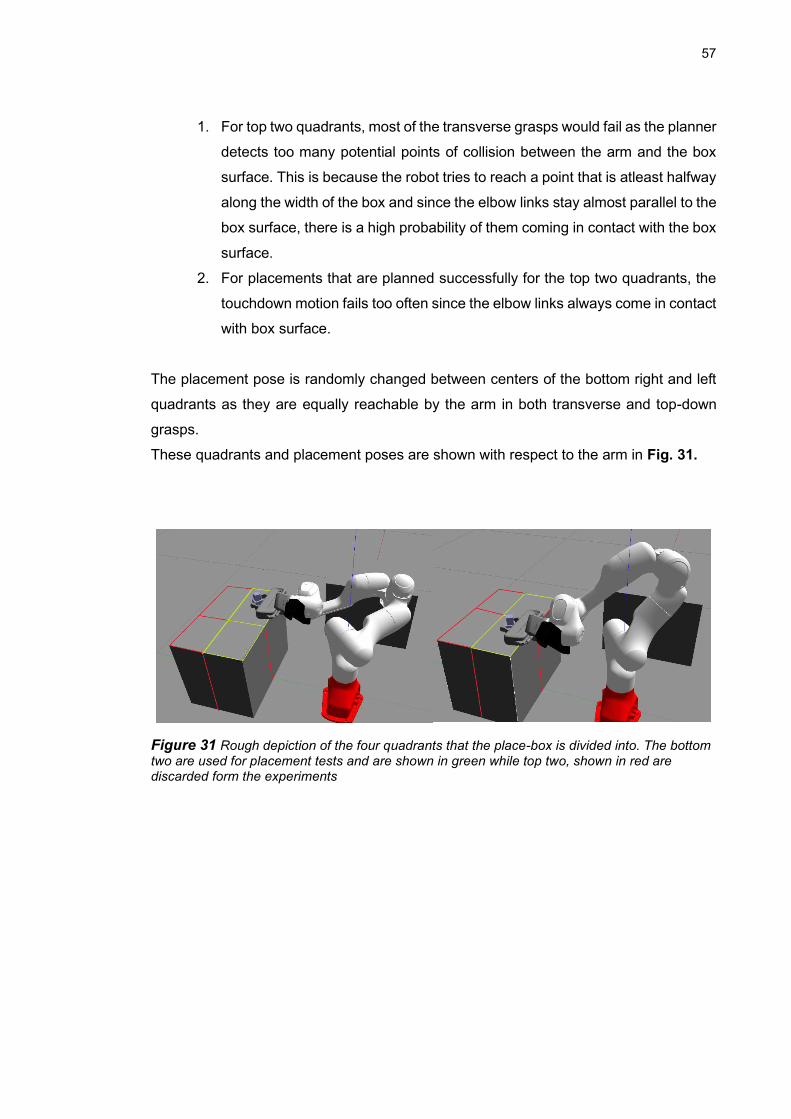
57
1. For top two quadrants, most of the transverse grasps would fail as the planner
detects too many potential points of collision between the arm and the box
surface. This is because the robot tries to reach a point that is atleast halfway
along the width of the box and since the elbow links stay almost parallel to the
box surface, there is a high probability of them coming in contact with the box
surface.
2. For placements that are planned successfully for the top two quadrants, the
touchdown motion fails too often since the elbow links always come in contact
with box surface.
The placement pose is randomly changed between centers of the bottom right and left
quadrants as they are equally reachable by the arm in both transverse and top-down
grasps.
These quadrants and placement poses are shown with respect to the arm in Fig. 31.
Figure 31 Rough depiction of the four quadrants that the place-box is divided into. The bottom two are used for placement tests and are shown in green while top two, shown in red are discarded form the experiments
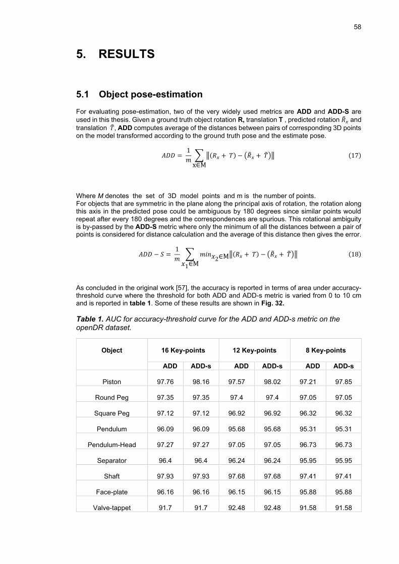
58
5. RESULTS
5.1 Object pose-estimation
For evaluating pose-estimation, two of the very widely used metrics are ADD and ADD-S are
used in this thesis. Given a ground truth object rotation R, translation T , predicted rotation �̃�𝑥 and
translation �̃�, ADD computes average of the distances between pairs of corresponding 3D points on the model transformed according to the ground truth pose and the estimate pose.
𝐴𝐷𝐷 = 1
𝑚∑ ‖(𝑅𝑥 + 𝑇) − (�̃�𝑥 + �̃�)‖
x∈M
(17)
Where M denotes the set of 3D model points and m is the number of points. For objects that are symmetric in the plane along the principal axis of rotation, the rotation along this axis in the predicted pose could be ambiguous by 180 degrees since similar points would repeat after every 180 degrees and the correspondences are spurious. This rotational ambiguity is by-passed by the ADD-S metric where only the minimum of all the distances between a pair of points is considered for distance calculation and the average of this distance then gives the error.
𝐴𝐷𝐷 − 𝑆 = 1
𝑚∑ 𝑚𝑖𝑛𝑥2∈M‖(𝑅𝑥 + 𝑇) − (�̃�𝑥 + �̃�)‖
𝑥1∈M
(18)
As concluded in the original work [57], the accuracy is reported in terms of area under accuracy-threshold curve where the threshold for both ADD and ADD-s metric is varied from 0 to 10 cm and is reported in table 1. Some of these results are shown in Fig. 32.
Table 1. AUC for accuracy-threshold curve for the ADD and ADD-s metric on the openDR dataset.
Object
16 Key-points
12 Key-points
8 Key-points
ADD ADD-s ADD ADD-s ADD ADD-s
Piston
97.76
98.16
97.57
98.02
97.21
97.85
Round Peg
97.35
97.35
97.4
97.4
97.05
97.05
Square Peg
97.12
97.12
96.92
96.92
96.32
96.32
Pendulum
96.09
96.09
95.68
95.68
95.31
95.31
Pendulum-Head
97.27
97.27
97.05
97.05
96.73
96.73
Separator
96.4
96.4
96.24
96.24
95.95
95.95
Shaft
97.93
97.93
97.68
97.68
97.41
97.41
Face-plate
96.16
96.16
96.15
96.15
95.88
95.88
Valve-tappet
91.7
91.7
92.48
92.48
91.58
91.58
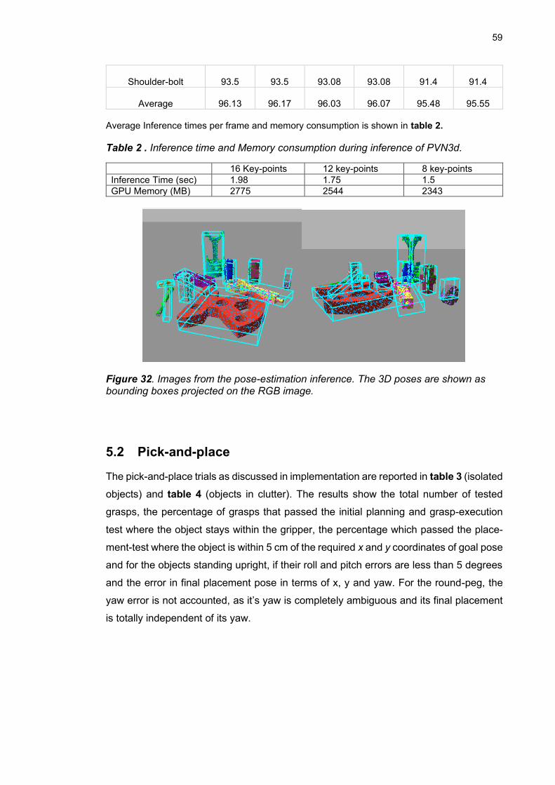
59
Shoulder-bolt
93.5
93.5
93.08
93.08
91.4
91.4
Average
96.13
96.17
96.03
96.07
95.48
95.55
Average Inference times per frame and memory consumption is shown in table 2.
Table 2 . Inference time and Memory consumption during inference of PVN3d.
16 Key-points 12 key-points 8 key-points
Inference Time (sec) 1.98 1.75 1.5
GPU Memory (MB) 2775 2544 2343
Figure 32. Images from the pose-estimation inference. The 3D poses are shown as bounding boxes projected on the RGB image.
5.2 Pick-and-place
The pick-and-place trials as discussed in implementation are reported in table 3 (isolated
objects) and table 4 (objects in clutter). The results show the total number of tested
grasps, the percentage of grasps that passed the initial planning and grasp-execution
test where the object stays within the gripper, the percentage which passed the place-
ment-test where the object is within 5 cm of the required x and y coordinates of goal pose
and for the objects standing upright, if their roll and pitch errors are less than 5 degrees
and the error in final placement pose in terms of x, y and yaw. For the round-peg, the
yaw error is not accounted, as it’s yaw is completely ambiguous and its final placement
is totally independent of its yaw.
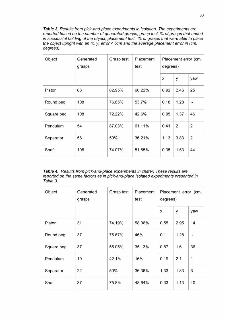
60
Table 3. Results from pick-and-place experiments in isolation. The experiments are reported based on the number of generated grasps, grasp test: % of grasps that ended in successful holding of the object, placement test: % of grasps that were able to place the object upright with an (x, y) error < 5cm and the average placement error in (cm, degrees).
Object Generated
grasps
Grasp test Placement
test
Placement error (cm,
degrees)
x y yaw
Piston 88 82.95% 60.22% 0.92 2.46 25
Round peg 108 76.85% 53.7% 0.18 1.28 -
Square peg 108 72.22% 42.6% 0.95 1.37 46
Pendulum 54 87.03% 61.11% 0.41 2 2
Separator 58 50% 36.21% 1.13 3.83 2
Shaft 108 74.07% 51.85% 0.35 1.53 44
Table 4. Results from pick-and-place experiments in clutter. These results are reported on the same factors as in pick-and-place isolated experiments presented in Table 3.
Object Generated
grasps
Grasp test Placement
test
Placement error (cm,
degrees)
x y yaw
Piston 31 74.19% 58.06% 0.55 2.95 14
Round peg 37 75.67% 46% 0.1 1.28 -
Square peg 37 55.05% 35.13% 0.87 1.6 36
Pendulum 19 42.1% 16% 0.19 2.1 1
Separator 22 50% 36.36% 1.33 1.83 3
Shaft 37 75.8% 48.64% 0.33 1.13 40
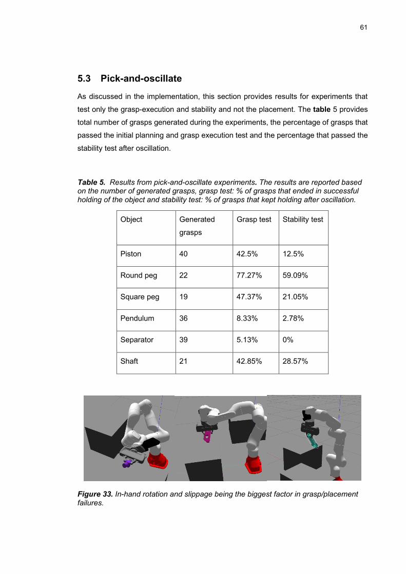
61
5.3 Pick-and-oscillate
As discussed in the implementation, this section provides results for experiments that
test only the grasp-execution and stability and not the placement. The table 5 provides
total number of grasps generated during the experiments, the percentage of grasps that
passed the initial planning and grasp execution test and the percentage that passed the
stability test after oscillation.
Table 5. Results from pick-and-oscillate experiments. The results are reported based on the number of generated grasps, grasp test: % of grasps that ended in successful holding of the object and stability test: % of grasps that kept holding after oscillation.
Object Generated
grasps
Grasp test Stability test
Piston 40 42.5% 12.5%
Round peg 22 77.27% 59.09%
Square peg 19 47.37% 21.05%
Pendulum 36 8.33% 2.78%
Separator 39 5.13% 0%
Shaft 21 42.85% 28.57%
Figure 33. In-hand rotation and slippage being the biggest factor in grasp/placement failures.
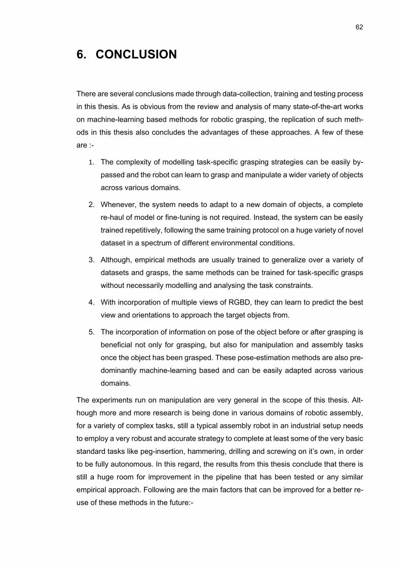
62
6. CONCLUSION
There are several conclusions made through data-collection, training and testing process
in this thesis. As is obvious from the review and analysis of many state-of-the-art works
on machine-learning based methods for robotic grasping, the replication of such meth-
ods in this thesis also concludes the advantages of these approaches. A few of these
are :-
1. The complexity of modelling task-specific grasping strategies can be easily by-
passed and the robot can learn to grasp and manipulate a wider variety of objects
across various domains.
2. Whenever, the system needs to adapt to a new domain of objects, a complete
re-haul of model or fine-tuning is not required. Instead, the system can be easily
trained repetitively, following the same training protocol on a huge variety of novel
dataset in a spectrum of different environmental conditions.
3. Although, empirical methods are usually trained to generalize over a variety of
datasets and grasps, the same methods can be trained for task-specific grasps
without necessarily modelling and analysing the task constraints.
4. With incorporation of multiple views of RGBD, they can learn to predict the best
view and orientations to approach the target objects from.
5. The incorporation of information on pose of the object before or after grasping is
beneficial not only for grasping, but also for manipulation and assembly tasks
once the object has been grasped. These pose-estimation methods are also pre-
dominantly machine-learning based and can be easily adapted across various
domains.
The experiments run on manipulation are very general in the scope of this thesis. Alt-
hough more and more research is being done in various domains of robotic assembly,
for a variety of complex tasks, still a typical assembly robot in an industrial setup needs
to employ a very robust and accurate strategy to complete at least some of the very basic
standard tasks like peg-insertion, hammering, drilling and screwing on it’s own, in order
to be fully autonomous. In this regard, the results from this thesis conclude that there is
still a huge room for improvement in the pipeline that has been tested or any similar
empirical approach. Following are the main factors that can be improved for a better re-
use of these methods in the future:-

63
1. The grasps performed based on pose-estimation can benefit from a wider variety
of dataset I.e., Varying lighting conditions, background clutter, different colors or
shades of the target objects, slightly different sizes or shapes of the target ob-
jects. All these aspects will lead to a better initial pose estimate and hence a
lesser error in grasping and placement poses.
2. The grasps performed without pose-estimation information should be trained on
a much wider variety of data I.e., large intra-class variations, objects rotated along
a wider variety of random poses than just simply lying on a flat surface, objects
with a variety of different heights from the flat surface. This lack of training, on the
particular dataset used in this thesis explains why so many of the generated
grasps fail for class-agnostic grasping method.
3. The huge placement errors in yaw for some objects and in x and y coordinates
for other, were found to be due to excessive in-hand sliding, rotation and swinging
during the experiments. This is illustrated in Fig. 33. This concludes a necessity
of use of a dextrous or a compliant gripper in future as compared to a simple
parallel gripper.
4. In order to successfully complete a basic assembly task, rather than just the
placement, in-hand pose estimation or pose-tracking of the target object com-
bined with the force feedbacks from the fingers can add a very useful information
on the status of the task and can make the assembly robust towards in-hand
rotations and slippage.
64
REFERENCES
[1] Du, Guoguang, Kai Wang and Shiguo Lian. “Vision-based Robotic Grasping from
Object Localization, Pose Estimation, Grasp Detection to Motion Planning: A Review.”
arXiv:1905.06658v1 [cs.RO], 16 May 2019.
[2] Caldera, Shehan; Rassau, Alexander; Chai, Douglas. "Review of Deep Learning
Methods in Robotic Grasp Detection." Multimodal Technologies Interact. 2, no. 3: 57.
(2018)
[3] Sahbani A., El-Khoury S., Bidaud P. “An overview of 3D object grasp synthesis al-
gorithms”, Robotics and Autonomous Systems, Volume 60, Issue 3, Pages 326-336,
March 2012.
[4] Bohg, Jeannette et al. “Data-Driven Grasp Synthesis—A Survey.” IEEE Transac-
tions on Robotics 30.2 (2014): 289–309. Crossref. Web.
[5] Clemens Eppner and Arsalan Mousavian and Dieter Fox. “A Billion Ways to Grasp:
An Evaluation of Grasp Sampling Schemes on a Dense, Physics-based Grasp Data
Set.”, 19th International Symposium of Robotics Research (ISRR),2019.
[6] Fabrizio Bottarel, Giulia Vezzani, Ugo Pattacini, and Lorenzo Natale. “GRASPA 1.0:
GRASPA is a Robot Arm graSping Performance benchmArk” - IEEE Robotics and Au-
tomation Letters, 2020.
[7] Sukharev AG. “Optimal strategies of the search for an extremum.” USSR Computa-
tional Mathematics and Mathematical Physics 11(4):119–137, 1971.
[8] Yershova A, Jain S, Lavalle SM, Mitchell JC. “Generating Uniform Incremental Grids
on SO(3) Using the Hopf Fibration.” The International journal of robotics research
29(7):801–812, 2010.
[9] A. Bicchi and V. Kumar, “Robotic grasping and contact.” IEEE Int. Conf. on Robotics
and Automation (ICRA),April 2000, invited paper, San Francisco.
[10] D. Prattichizzo, M. Malvezzi, M. Gabiccini, and A. Bicchi. “On the manipulability el-
lipsoids of underactuated robotic hands with compliance.” Robotics and Autonomous
Systems, vol. 60, no. 3, pp. 337 –346, 2012.
[11] M. A. Roa and R. Suárez, “Computation of independent contact regions for grasp-
ing 3-d objects.” IEEE Trans. on Robotics, vol. 25, no. 4, pp.839–850, 2009.
[12] A. Rodriguez, M. T. Mason, and S. Ferry, “From Caging to Grasping, in Robotics.”
Science and Systems (RSS), Apr. 2011.
[13] V.-D. Nguyen, “Constructing force-closure grasps.” IEEE International Conference
on Robotics and Automation, San Francisco, CA, USA, 1986, pp. 1368-1373, doi
65
[14] R. Krug, D. N. Dimitrov, K. A. Charusta, and B. Iliev, “On the efficient computation
of independent contact regions for force closure grasps.” IEEE/RSJ Int. Conf. on Intel-
ligent Robots and Systems (IROS). IEEE, pp. 586–591, 2010.
[15] Andreas ten Pas and Marcus Gualtieri and Kate Saenko and Robert Platt, “Grasp
Pose Detection in Point Clouds.”, arXiv:1706.09911v1 [cs.RO], 29 Jun 2017.
[16] Hongzhuo Liang, Xiaojian Ma, Shuang Li, Michael Görner, Song Tang, Bin Fang,
Fuchun Sun, Jianwei Zhang, “PointNetGPD: Detecting Grasp Configurations from Point
Sets.” arXiv:1809.06267v4 [cs.RO], 18 Feb 2019.
[17] Arsalan Mousavian, Clemens Eppner, Dieter Fox, “6-DOF GraspNet: Variational
Grasp Generation for Object Manipulation.” arXiv:1905.10520v2 [cs.CV] 17, Aug
2019
[18] D. G. Kirkpatrick, B. Mishra, and C. K. Yap, “Quantitative Steinitz’s theorems with
applications to multi-fingered grasping.” Proceedings of the twenty-second annual ACM
symposium on Theory of Computing https://doi.org/10.1145/100216.100261, Pages
341–351 , April 1990.
[19] Lerrel Pinto, Abhinav Gupta, “Supersizing Self-supervision: Learning to Grasp from
50K Tries and 700 Robot Hours.” arXiv:1509.06825v1 [cs.LG], 23 Sep 2015.
[20] D. Guo, F. Sun, H. Liu, T. Kong, B. Fang and N. Xi, "A hybrid deep architecture for
robotic grasp detection," IEEE International Conference on Robotics and Automation
(ICRA), Singapore, 2017, pp. 1609-1614, doi: 10.1109/ICRA.2017.7989191, 2017.
[21] K. He, G. Gkioxari, P. Dollár and R. Girshick, "Mask R-CNN," 2017 IEEE Interna-
tional Conference on Computer Vision (ICCV), Venice, 2017, pp. 2980-2988, doi:
10.1109/ICCV.2017.322.
[22] S. Ren, K. He, R. Girshick and J. Sun, "Faster R-CNN: Towards Real-Time Object
Detection with Region Proposal Networks," in IEEE Transactions on Pattern Analysis
and Machine Intelligence, vol. 39, no. 6, pp. 1137-1149, 1 June 2017, doi:
10.1109/TPAMI.2016.2577031.
[23] T. Lin, et al., "Feature Pyramid Networks for Object Detection," in 2017 IEEE Con-
ference on Computer Vision and Pattern Recognition (CVPR), Honolulu, HI, USA, 2017
pp. 936-944. doi: 10.1109/CVPR.2017.106
[24] David G. Lowe. Object recognition from lo-cal scale-invariant features. InProceed-
ings of the Interna-tional Conference on Computer Vision-Volume 2 - Volume2, ICCV
’99, pages 1150–, 1999.
[25] Herbert Bay, Tinne Tuytelaars, and LucVan Gool. “Surf: Speeded up robust fea-
tures.” In European conference on computer vision, pages 404–417. Springer,2006.
[26] Raul Mur-Artal, Jose Maria Mar-tinez Montiel, and Juan D Tardos. “Orb-slam: a
versatile and accurate monocular slam system.” IEEE transactionson robotics,
31(5):1147–1163, 2015.
66
[27] R. B. Rusu, N. Blodow, and M. Beetz, “Fast point feature histograms (fpfh) for 3d
registration.” In IEEE International Conference on Robotics and Automation, pages
3212–3217, May 2009.
[28] Samuele Salti, Federico Tombari, and Luigi Di Stefano. “Shot: Unique signatures
of histograms for surface and texture description.” Computer Vision and Image Under-
standing, 125:251 – 264, 2014.
[29] Pham, Quang-Hieu & Uy, Mikaela Angelina & Hua, Binh-Son & Nguyen, Duc
Thanh & Roig, Gemma & Yeung, Sai-Kit., “LCD: Learned Cross-Domain Descriptors
for 2D-3D Matching.” Proceedings of the AAAI Conference on Artificial Intelligence. 34.
11856-11864. 10.1609/aaai.v34i07.6859, (2020).
[30] Y. Hu, J. Hugonot, P. Fua and M. Salzmann, "Segmentation-Driven 6D Object
Pose Estimation." 2019 IEEE/CVF Conference on Computer Vision and Pattern Recog-
nition (CVPR), Long Beach, CA, USA, pp. 3380-3389, doi: 10.1109/CVPR.2019.00350.
2019.
[31] Vorobyov, M. “Shape Classification Using Zernike Moments.” (2011).
[32] Stefan Hinterstoisser, Vincent Lepetit, Slobodan Ilic, Stefan Holzer, GaryBradski,
Kurt Konolige, Nassir Navab, “Model Based Training, Detection and Pose Estimation of
Texture-Less 3D Objects in Heavily Cluttered Scenes.”, 2012.
[33] Berk Calli, Arjun Singh, Aaron Walsman, Siddhartha Srinivasa, Pieter Abbeel and
Aaron Dollar, “The YCB Object and Model Set: Towards Common Benchmarks for Ma-
nipulation Research.”, Conference Paper, Proceedings of IEEE International Confer-
ence on Advanced Robotics (ICAR), July, 2015.
[34] Xiang, Y. et al. “PoseCNN: A Convolutional Neural Network for 6D Object Pose
Estimation in Cluttered Scenes.” ArXiv abs/1711.00199, (2018).
[35] Capellen, Catherine & Schwarz, Max & Behnke, Sven, “ConvPoseCNN: Dense
Convolutional 6D Object Pose Estimation.” 15th International Conference on Computer
Vision Theory and Applications, (2020).
[36] Song, Chen et al. “HybridPose: 6D Object Pose Estimation Under Hybrid Repre-
sentations.” 2020 IEEE/CVF Conference on Computer Vision and Pattern Recognition
(CVPR): 428-437, (2020).
[37] Peng, S. et al. “PVNet: Pixel-Wise Voting Network for 6DoF Pose Estimation.”
2019 IEEE/CVF Conference on Computer Vision and Pattern Recognition (CVPR) :
4556-4565, (2019).
[38] Manuelli, Lucas et al. “kPAM: KeyPoint Affordances for Category-Level Robotic
Manipulation.” ArXiv abs/1903.06684, 2019.
[39] Wang, He et al. “Normalized Object Coordinate Space for Category-Level 6D Ob-
ject Pose and Size Estimation.” 2019 IEEE/CVF Conference on Computer Vision and
Pattern Recognition (CVPR): 2637-2646, 2019.
67
[40] F. T. Pokorny and D. Kragic, “Classical grasp quality evaluation: New theory and
algorithms,” in IEEE/RSJ International Conference on Intelligent Robots and Systems
(IROS), 2013.
[41] J. Mahler et al., "Dex-Net 1.0: A cloud-based network of 3D objects for robust
grasp planning using a Multi-Armed Bandit model with correlated rewards," 2016 IEEE
International Conference on Robotics and Automation (ICRA), pp. 1957-1964, doi:
10.1109/ICRA.2016.7487342, 2016, Stockholm.
[42] Jeffrey Mahler, Jacky Liang, Sherdil Niyaz, Michael Laskey, Richard Doan, Xinyu
Liu, Juan Aparicio Ojea, and Ken Goldberg, Dept. of EECS, University of California,
Berkeley, “Dex-Net 2.0: Deep Learning to Plan Robust Grasps with Synthetic Point
Clouds and Analytic Grasp Metrics”, arXiv:1703.09312v3 [cs.RO], 8 Aug 2017.
[43] Lenz, H. Lee, and A. Saxena, “Deep learning for detecting robotic grasps,”I. J. Ro-
botics Res., vol. 34, no. 4-5, pp. 705–724, 2015.
[44] D. Park and S. Y. Chun, “Classification based grasp detection using spatial trans-
former network.” CoRR, 2018.
[45] M. Jaderberg, K. Simonyan, A. Zisserman, and K. Kavukcuoglu,“Spatial Trans-
former Networks,” in NIPS, 2015.
[46] Redmon and Angelova, Joseph Redmon and Anelia Angelova, “Real-time grasp
detection using convolutional neural networks.” In IEEE International Conference on
Robotics and Automation (ICRA), pages 1316–1322.IEEE, 2015.
[47] Di Guo, Tao Kong, Fuchun Sun, and Huaping Liu, “Object discovery and grasp de-
tection with a shared convolutional neural network.” In IEEE Inter-national Conference
on Robotics and Automation (ICRA),pages 2038–2043. IEEE, 2016.
[48] C. Ferrari and J. Canny, “Planning optimal grasps.” in Proc. IEEE Int. Conf. Robot.
Autom., 1992, pp. 2290–2295.
[49] Guo, Yulan et al. “Deep Learning for 3D Point Clouds: A Survey.” IEEE transac-
tions on pattern analysis and machine intelligence, (2020).
[50] Y. Zhou and O. Tuzel, "VoxelNet: End-to-End Learning for Point Cloud Based 3D
Object Detection," 2018 IEEE/CVF Conference on Computer Vision and Pattern
Recognition, pp. 4490-4499, doi: 10.1109/CVPR.2018.00472, Salt Lake City, UT,
2018.
[51] Wang, Yue et al. “Dynamic Graph CNN for Learning on Point Clouds.” ACM Trans.
Graph. 38, 146:1-146:12, (2019).
[52] Weijing Shi and Ragunathan (Raj) Rajkumar, Carnegie Mellon University Pitts-
burgh, PA 15213 Point-GNN: “Graph Neural Network for 3D Object Detection in a Point
Cloud.” arXiv:2003.01251v1 [cs.CV] 2 Mar 2020
68
[53] Charles R. Qi, Hao Su, Kaichun Mo, Leonidas J. Guibas, “PointNet: Deep Learning
on Point Sets for 3D Classification and Segmentation.” arXiv:1612.00593v2 [cs.CV] 10
Apr 2017.
[54] Charles R. QiLi YiHao SuLeonidas J. GuibasStanford University, “PointNet++:
Deep Hierarchical Feature Learning on Point Sets in a Metric Space.”
arXiv:1706.02413v1 [cs.CV] ,7 Jun 2017.
[55] A. Zeng, S. Song, M. Nießner, M. Fisher, J. Xiao and T. Funkhouser, "3DMatch:
Learning Local Geometric Descriptors from RGB-D Reconstructions," 2017 IEEE Con-
ference on Computer Vision and Pattern Recognition (CVPR), Honolulu, HI, 2017, pp.
199-208, doi: 10.1109/CVPR.2017.29.
[56] Zhao, Binglei et al. “REGNet: REgion-based Grasp Network for Single-shot Grasp
Detection in Point Clouds.” ArXiv abs/2002.12647 (2020): n. pag.
[57] Y. He, W. Sun, H. Huang, J. Liu, H. Fan and J. Sun, "PVN3D: A Deep Point-Wise
3D Keypoints Voting Network for 6DoF Pose Estimation," 2020 IEEE/CVF Conference
on Computer Vision and Pattern Recognition (CVPR), Seattle, WA, USA, 2020, pp.
11629-11638, doi: 10.1109/CVPR42600.2020.01165.
[59] Gonzalez, M. et al. “YOLOff: You Only Learn Offsets for robust 6DoF object pose
estimation.” ArXiv abs/2002.00911 (2020): n. pag.
[60] Zapata-Impata, Brayan S., et al. “Fast Geometry-Based Computation of Grasping
Points on Three-Dimensional Point Clouds.” International Journal of Advanced Robotic
Systems, Jan. 2019.
[61] J. Goodfellow, Jean Pouget-Abadie, Mehdi Mirza, BingXu, David Warde-Farley,
Sherjil Ozair, Aaron C. Courville,and Yoshua Bengio, “Generative adversarial net-
works.”, Neural Information Processing Systems (NeurIPS), 2014.
[62] C. Wang et al., "DenseFusion: 6D Object Pose Estimation by Iterative Dense Fu-
sion," 2019 IEEE/CVF Conference on Computer Vision and Pattern Recognition
(CVPR), pp. 3338-3347, doi: 10.1109/CVPR.2019.00346, Long Beach, CA, USA,
2019.
[63] Collins K, Palmer AJ, Rathmill K, “The development of a European benchmark for
the comparison of assembly robot programming systems.” In: Robot technology and
applications(Robotics Europe Conference), pp 187–199, (1985).
[64] H. Zhao, J. Shi, X. Qi, X. Wang, and J. Jia. “Pyramid scene parsing network." In
Proceedings of the IEEE conference oncomputer vision and pattern recognition, pages
2881–2890, 2017.
[65] D. Comaniciu and P. Meer. “Mean shift: A robust approach toward feature space
analysis.” IEEE Transactions on Pattern Analysis & Machine Intelligence, (5):603–619,
2002. 3, 9
[66] Diederik P. Kingma and Max Welling.”Auto-encoding variational bayes.” Interna-
tional Conference on Learning Representations (ICLR), 2014.
69
[67] Angel X Chang, Thomas Funkhouser, Leonidas Guibas, Pat Hanrahan, Qixing
Huang, Zimo Li, Silvio Savarese,Manolis Savva, Shuran Song, Hao Su, et al, “Shap-
enet: An information-rich 3d model repository.”, arXiv preprintarXiv:1512.03012, 2015.
[68] Sachin Chitta, Eitan Marder-Eppstein, Wim Meeussen, Vijay Pradeep, Adolfo
Rodríguez Tsouroukdissian, et al. “ros_control: A generic and simple control framework
for ROS.” The Journal of Open Source Software, 2017, 2 (20), pp.456 - 456.
ff10.21105/joss.00456ff. ffhal-01662418.
[69] Coleman, D. et al. “Reducing the Barrier to Entry of Complex Robotic Software: a
MoveIt! Case Study.” ArXiv abs/1404.3785 (2014): n. pag.
[70] J. Pan, S. Chitta, and D. Manocha, “Fcl: A general purpose library for collision and
proximity queries,” in Robotics and Automation (ICRA),2012 IEEE International Confer-
ence on, 2012, pp. 3859–3866. 2.2
[71] R. Smits. Kdl: Kinematics and dynamics library. [Online].Available: http://www.oro-
cos.org/kdl 2.2, (2013, Oct.)
[72] Erdal Pekel Integrating FRANKA EMIKA Panda robot into Gazebo, January 14,
2019, Edral’s Blog: https://erdalpekel.de/?p=55
[73] Martin John Baker,“Maths - Projections of lines on planes”, EuclideanSpace -
Mathematics and Computing: https://www.euclideanspace.com/maths/geometry/ele-
ments/plane/lineOnPlane/index.htm
[74] C. Mitash, R. Shome, B. Wen, A. Boularias and K. Bekris, "Task-Driven Perception
and Manipulation for Constrained Placement of Unknown Objects," in IEEE Robotics
and Automation Letters, vol. 5, no. 4, pp. 5605-5612, Oct. 2020, doi:
10.1109/LRA.2020.3006816.
[75] K. Van Wyk, M. Culleton, J. Falco and K. Kelly, "Comparative Peg-in-Hole Testing
of a Force-Based Manipulation Controlled Robotic Hand," in IEEE Transactions on Ro-
botics, vol. 34, no. 2, pp. 542-549, April 2018, doi: 10.1109/TRO.2018.2791591.
[76] Watson, J. et al. “Autonomous industrial assembly using force, torque, and RGB-D
sensing.” Advanced Robotics 34 (2020): 546 - 559.
[77] Richard M Murray, Zexiang Li, S Shankar Sastry, and S Shankara Sastry, “A math-
ematical introduction to robotic manipulation.” CRC press, 1994