a fast, flexible, particle-system model for cloth draping ...frey/papers/draping/eberhardt b., a...
TRANSCRIPT
Computer Graphics in Textiles and Apparel
Particle- S y s t ode1 for CI raping
or centuries people have admired the flow- F ing robes in works by such artists as Raphael and Michelangelo. The sculpted or painted folds of cloth not only demonstrate the artist’s techni- cal skill but also reinforce the illusion of reality. The draping of virtual cloth is a challenge not only in art, but also in the generation of virtual worlds in comput- er science.
Engineers, mathematicians, and physicists have developed theories and accurate models to predict the behavior of stiff membranes made from materials such
Animating the drape of
different cloths must
address complex physical
behaviors. This particle
approach uses optimizations
that make it faster than
earlier implementations and
allow it t o simulate behavior
over time.
as steel and wood. Good mechani- cal models for textiles, however, have only recently become avail- able. One reason is that textiles undergo large deformations. To determine qualitative behavior, tex- tile industries use standardized measurements like the Kawabata evaluation system.’
In computer graphics, Weil‘ came up with an approach in 1986 that pro- duced an image of “cloth draping” by interpolating surfaces between curves. More recently, computer sci- entists and engineers have used finite elements to model ~ l o t h . ~ . ~
Terzopoulos6 tried to establish a physical basis for the behavior of deformable materials. He solved problems numerically by describing
large deformations as the result of small forces and by calculating the deformation energy of the material only from the given geometrical data. His model describes the physical behavior of cloth exactly and distinguish- es it from any stiff material such as iron, plastic, or alu- minum.
Breen, House, and Wozny7 proposed an approach that used coupled particles to model the cloth through a min- imized energy function. Their work motivated the work presented here. However, we use a different, faster tech- nique to calculate the exact particle trajectories. Our
Bernhard Eberhardt, Andreas Weber, and Wolfgang Strasser University of Tubingen, Germany
model incorporates cloth-specific properties, such as hys- teresis of the forces, as well as measured experimental data. Moreover, flexibility in the energy functions sup- ports the simulation of effects like the crease in trousers.
Particle systems Coupled particle systems first appeared in computer
graphics in the work of Reynolds.8 He described a parti- cle system as a set ofparticles interactingwith each other according to certain laws imposed by the problem. Apar- ticle system offers a viable solution to a problem if you know how the position of one element changes over time depending on the properties of the other elements. The power of this idea is evident in the many recent applica- tions of these systems, ranging from molecular dynam- ics to the calculation of colliding galaxies.
In their significant paper on the use of particle sys- tems to model the drape of woven cloth, Breen, House, and Wozny7 described woven fabrics as a set of mass points falling in a gravitational field according to phys- ical laws. This description is suitable for obtaining real- istic predictions of the interactions of draping cloth with various environments.
The system described here extends the model of Breen, House, and Wozny. We introduce techniques to model measured force data exactly and thus cloth-spe- cific properties such as anisotropic behavior and hys- teresis. Moreover, we extended the particle system to model air resistance. Our system allows a dynamic sim- ulation that shows the effects on falling cloth from air resistance, wind, moving bodies, and surface friction.
The physical basis The starting point of modeling the drape of cloth via
particle systems is the simulation of the fall or draping motion of a cloth in some environment such as air, water, or even oil. This dynamical simulation requires calculation of the exact trajectories of a falling particle. The trajectory is described through a physical model of the cloth and must include all forces acting on a single particle. The superposition of these forces gives the direction and acceleration of the moving particle.
52 September 1996 0272-1 7-1 6196185.00 0 7 996 IEEE

The weft and warp directions give the internal struc- ture of a woven cloth. A rectangular grid can model this structure in a natural way7 For a physical model of cloth, we consider the following “internal forces”:
tension shearing
w bending
All three forces depend strongly on the type of cloth to be modeled. Kawabata investigated these forces in detail.’ Figure 1 presents an example of a Kawabata plot for the experimental data of a cotton shearing test. His experiments showed that
the forces are linear only for small elongations (deformations) ; linear functions can approximate the shearing and bending forces for smaller angles quite well; over the full range of possible bend and shear angles, shearing and bending forces are nonlinear and show hysteresis effects; the forces are different in the weft and warp direc- tions: and
w there are maximum forces in the sense that larg- er forces will tear the cloth.
The trajectory of a particle depends not only on the internal structure of the cloth, but also on the sur- rounding environment. We must therefore also consid- er “external forces” such as
gravitation; air resistance; interactions with solid bodies, specifically, friction at the surface and reactive forces prohibiting pen- etration of solid bodies and penetration of the cloth with itself; and blowing of air, moving bodies.
The latter two forces can be modeled easily because they depend only on local properties. Air resistance, however, depends on the global shape of the falling cloth. The air resistance coefficient cw varies from 0.34 for a convex hemisphere to 1.1 for a square and 1.33 for a concave hemisphere.’ Ideally, an individual parame- ter should be set for each particle.
Mathematical aspects Consider a set of n particles. Given the masses of the
particles, we can describe the state of our particle system at time t by the sets xo, XI, XZ, x3, . . . , x3 n-l and YO, VI, VZ, v3,
. . . , v3n-1, where the vectors (XO, XI, XZ), (x3, x~,xs) , and so forth are the locations of our particles, and (VO, VI, V Z ) ,
(v3, v4, VS), . . . are the velocities respectively at time t. The forces described above are pushing the particles
through space. Using forces to calculate the trajectory of a particle is difficult, since we must deal with the superposition of many forces. In many cases, however, forces are given as the gradient of a potential or energy function V. D’AIembert and Lagrange elucidated the advantages of using potentials two centuries ago. The
Lagrange equation
gives a second-order differential equation for each coor- dinate of a moving particle, where L = Ekln - Vis the Lagrange function with Vbeing a cloth-specific potential and Ek,, the kinetic energy of the system (for example, see Arnold”). The Lagrange equation fully describes the trajectory of the moving particle.
What does the potential V look like for our cloth model? As described above we consider tension, shear- ing, and bending as internal forces and therefore get the respective energy functions Et,, E,,, and Eb, for a particle i. In addition, each particle has a potential energyEPot, which is the usual energy depending on the height of the particle. Adding up all energies of all particles we get the Lagrange function
where n is the number of particles. As we will see later, our potential Vdepends only on the locationxo, X I , XZ, x3, . . . , X3.n-l of the particles, whereas the kinetic energyEh is a function of YO, VI, V Z , . . . , ~ 3 . n - l . Thus, L is now a func- tion of dimension 6 times the number of particles.
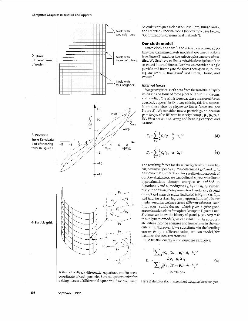
The dimension of the function is not a serious prob- lem, since we now take the partial derivative ofL on the right side in Equation 1 with respect to the coordinate of a single particle. We obtain a “simple” function for the differential equation, because most of the variables of L vanish. The onlyvariables remaining are the coordinates of coupled particles. Moreover, because of the symme- try of our particle grid, this function has the same form for most of the particles, differing only in the indices. We only need to consider the three cases shown in Figure 2 (next page), depending on the number of neighbors, that is, nodes with two, three, and four neighbors.
The partial differential equation is now reduced to a
IEEE Computer Graphics and Applications
1 AKawabata plot of a cotton shearing test.
53
Computer Graphics in Textiles and Apparel
2 Three different cases of nodes.
!3 Piecewise linear Kawabata plot of shearing force in Figure 1.
4 Particle grid.
54
‘. Node with I two neighbors I
.. 15 < ,
/, ,‘ , / 2 , ’ 4 6 8
-1 0
-1 5
system of ordinary differential equations, one for each coordinate of each particle. Several options exist for solving this set of differential equations.” We have tried
September 1996
several techniques such as the Cash-Karp, Runge-Kutta, and Bulirsch-Stoer methods (for example, see below, “Optimizations for numerical methods”).
Our cloth model Since cloth has a weft and a warp direction, a rec-
tangular grid immediately models these two directions (see Figure 2) and thus the anisotropic structure of tex- tiles. We first have to find a suitable description of the so-called internal forces. For this we consider a single particle and investigate the forces acting on it, follow- ing the work of Kawabata‘ and Breen, House, and ~ o z n y . ~
Internal forces We get empirical cloth data from the Kawabata exper-
iments in the form of force plots of tension, shearing, and bending. Our aim is to model these measured forces as exactly as possible. One way of doing this is to approx- imate these plots by piecewise linear functions (see Figure 3). We consider now a particle PO at location po = (x~,yo, 20) E IR3with four neighbors PI, p2, p3, p4 E
IR3. We start with shearing and bending energies and assume
(3)
The resulting forces for these energy functions are lin- ear, having slopes C,, c b . We determine C,, cb and h,, h b
as shown in Figure 3. Thus, for small neighborhoods of our Kawabata plots, we can define the piecewise linear approximations through energies as defined in Equations 3 and 4, modifymg C,, cb and h,, hb, respec- tively. In addition, these parameters C and h also depend on weft and warp direction (indicated in Figure 3 as C,,,, and h,,,, for a shearing-warp approximation). In our implementation we have stored different values of C and h for every single degree, which gives a quite good approximation of the force plots (compare Figures 1 and 3). Once we know the history of 9 and y (an easy task in our dynamic model), we can substitute the appropri- ate values into the energies and hence later in the cal- culations. Moreover, if we substitute z i n the bending energy Eb by a different value, we can model, for instance, the crease in trousers.
The tension energy is implemented as follows:
Here d, denotes the unstretched distance between par-
ticle Po and pi. It lets us distinguish between repelling and stretching forces on the textiles. Again Ci,t, and Ci,tz depend on weft and warp direction. Breen, House, and Wozny7 took slightly different polynomials of degree 4 and 5. Their polynomials and the ones we use give quite similar results for the tension energy, if the constants are set correctly. These tension energies have proved appropriate for modeling woven ~ 1 0 t h . ~
For the Lagrange function we also need the following energies:
E,, =- ‘mi..: 3.
and the potential energies
With Equations 3 through 7 we have defined the ener- gies for particles with four neighbors. To get the Lagrange function, we must add all the energies for the n particles and eliminate the redundant energies (for particles with fewer than four neighbors).
The resulting Lagrange function is then differentiat- ed properlywith respect to the coordinates. We do this symbolically using the computer algebra system Maple,” which allowed us to generate optimized “C code” for the resulting functions of the differential equa- tion (see also below, “Optimizations by computer alge- bra techniques”).
Air resistance and external forces Air resistance is calculated by
where p is the specific weight of air, cw is the resistance coefficient, and A is the surface perpendicular to the velocity vL of particle i.
It is not easy to determine the exact value for c, for each particle, since it depends on the location of all par- ticles of the cloth. Therefore, we assume in our model the same value for cw for the particles with four neigh- bors, since they are “inside” the cloth. At the border we have two cases. Particles with three neighbors are part of an edge and those with two neighbors create an edge (see Figure 2). Thus the air may flow around them. From aerodynamics we know that this “flowing around” an edge or corner causes strong turbulences on the back- side of the cloth. Hence the friction, and the c, is high- er than in the middle of the cloth.
This model of air resistance is very simple and could be improved, but calculating an individual cw for each particle is a difficult and expensive task. We have achieved good results using this model, which demon- strates interesting dynamical effects (see Figure 8).
Adding the computations for the air resistance to our model is not so expensive as you might expect. Since we have already calculated angles and distances in our Maple procedure for the energies, it is easy to calculate the area A perpendicular to the velocity v,. Therefore,
we calculate the air resistance force in Maple and add it to the second derivative ofL.
In addition to air resistance, we can add arbitrary forces at this point to model blowing air, moving bod- ies, strokes on the cloth, and so on.
Interaction with environment An important issue in modeling cloth is to determine
its interaction or penetration with itself and its sur- roundings. In fact, you have only half the story without it. As described earlier, we calculate the trajectory of a particle via an integration of the Lagrange differential equation. To be more precise, we solve an initial value problem. The initial values-that is, the locations and velocities of the particles-are well defined before we start a simulation via a Runge-Kutta or other integra- tion method.
Between two simulation steps, we detect penetration and adjust the locations and velocities-the new initial values-according to physics. At this point we can dis- tinguish between interaction of the cloth with itself or with any other objects. This distinction is necessary because the way we calculate the reflected position is different if different materials are coming together.
Given the initial position PO of a particle, we start an interpolation of the differential equation. The new posi- tion of the particle is then PI. We send a ray R from PO to PI. If this ray intersects an obstacle at pointP, we cal- culate and store the surface normal N at the point together with the material. A flag is set to indicate the detection of an intersection. This flag is used to modify the velocities and accelerations in the following calcu- lations. We allow onlyvelocities, with no direction com- ponent opposite to the normal N at P. This prevents further penetration. In addition we adjust the location of the particle to
(9)
where &in > 0 is the minimal ray length ofR. To be more precise, accelerations and velocities, in
case of penetration, are modified as follows: Assume we have a velocity Void = Vnormal + vhor, where Vnormal is the component of vold parallel to the intersection normal I , and Vhor is the perpendicular component to I,. Then we calculate
vn, = fric-coeff . Vhor
+ fric-coeff . I I vnormai I I . In (10)
Both coefficients, fric-coeff and refl-coeff, depend strongly on material properties. In the case of interact- ing textiles, we can get some clues from Kawabata exper- iments on compression and surface.
Optimizations by computer algebra We used the Maple computer algebra system” to
compute the forces and thus the resulting accelerations defining particle movement in symbolic form. The sym- metry of the particle grid (see Figure 4) lets us use Maple’s C-code generator to obtain the code for the acceleration, that is, the flow function of the differential
IEEE Computer Graphics and Applications 55
compurer clrapnics I iexriies anu Apparel T
56
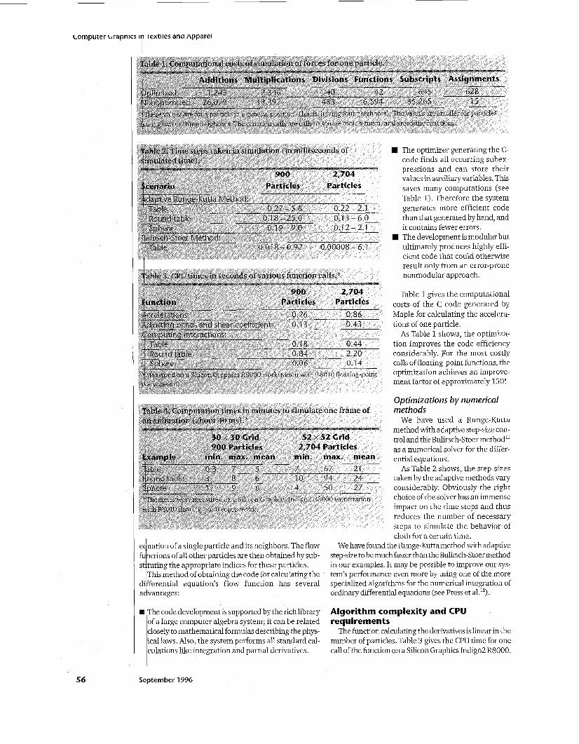
Table 2. Time steps tahen in simulation (in milliseconds of simulated time). -LyI .,* .uIILLyL --- -
900 2,704 Scenario Particles Particles
Adaptive Runge-Kulld Method: 0.27 - 5.8
0.1 8 - 25.0 0.22 - 2.1 0.1 3 - 6.0
Table Round table
- .- ._ -- .- ~ __ ___- -
Spiiei e 0.1 9 - 9.0 0.1 2 - 2.1 Bulirsch-Stoer Method:
Table 0.01 8 - 0.92 0.00008 - 6 1
The optimizer generating the C- code finds all occurring subex- pressions and can store their values in auxiliary variables. This saves many computations (see Table 1). Therefore the system generates more efficient code than that generated by hand, and it contains fewer errors. The development is modular but ultimately produces highly effi- cient code that could otherwise result only from an error-prone nonmodular approach.
Table 1 gives the computational costs of the C code generated by Maple for calculating the accelera- tions of one particle.
As Table 1 shows, the optimiza- tion improves the code efficiency considerably. For the most costly calls of floating-point functions, the optimization achieves an improve- ment factor of approximately 150!
Optimizations by numerical methods
We have used a Runge-Kutta method with adaptive step-size con- trol and the Bulirsch-Stoer method'' as a numerical solver for the differ- ential equations.
As Table 2 shows, the step-sizes taken by the adaptive methods vary considerably. Obviously the right choice of the solver has an immense impact on the time steps and thus reduces the number of necessary steps to simulate the behavior of cloth for a certain time.
We have found the Runge-Kutta method with adaptive step-size to be much fasterthanthe Bulirsch-Stoermethod in our examples. It may be possible to improve our sys- tem's performance even more by using one of the more specialized algorithms for the numerical integration of ordinary differential equations (see Press et a1.l').
equation of a single particle and its neighbors. The flow fuw of all other particles are then obtained by sub- st tuting the appropriate indices for these particles.
This method of obtaining the code for calculating the di ferential equation's flow function has several a k vantages:
The code development is supported by the richlibrary of a large computer algebra system; it can be related closely to mathematical formulas describing the phys- ical laws. Also, the system performs all standard cal- culations like integration and partial derivatives.
Algorithm complexity and CPU requirements
The function calculating the derivatives is linear in the number of particles. Table 3 gives the CPU time for one call of the function on a Silicon Graphics Indigo2 R8000.
Sebtem ber 1996

The function adjusting the bend and shear coefficient according to the hysteresis curve of a specific material is also linear in the number of particles. It is called less fre- quently than the function calculating the accelerations. Using the adaptive Runge-Kutta method, the number of calls to accelerations is about 6 to 10 times higher (which varies depending on the necessary corrections of the step sizes and is hard to predict, see below).
The complexity of the computation of interactions with the environment and possible penetrations of the cloth with itself is proportional to the product of the number of particles and the number of surfaces of the interacting environment. Although the theoretical com- plexity is not affected, the necessary computations can be reduced considerably by standard optimization tech- niques used in ray tracing (3D grids or hierarchical structures).
Because of the self-correcting nature of the adaptive step-size methods for solving an ordinary differential equation, the number of needed calls to the accelera- tion function and other auxiliary functions varies con- siderably. A theoretical prediction of them for a differential equation involving several thousand vari- ables, as in our examples, is extremely difficult and well beyond the scope of this article.
Table 4 summarizes the needed computation times for several of our examples. The step sizes-that is, the time that could be simulated by one call to an adaptive step-size solver-varied considerably. Table 2 includes
results for some of our examples. The function calculating the acceleration takes
between 77 and 86 percent of the total computation time. The computation of the interactions takes about 6 to 15 percent of the computation time (depending on the example). The adjustment of the bend and shear coeffi- cients takes about 6 to 8 percent. All other computations require less than 2 percent of the total CPU time.
Examples Figure 5 shows a falling tablecloth. The simulation
was performed on a Silicon Graphics Indigo2 R8000. We used a 52 x 52 particle grid and simulated a cotton polyester blend with different bend coefficients cb for the weft and warp directions, taking the values from Breen, House, and W o z n ~ . ~ Output is an Inventor ASCII file rendered using the Davis-Software at the Wilhelm- Schickard-Institut f i r InfomatiWGraphisch Interaktive Systeme (WS1/GRIS).l3
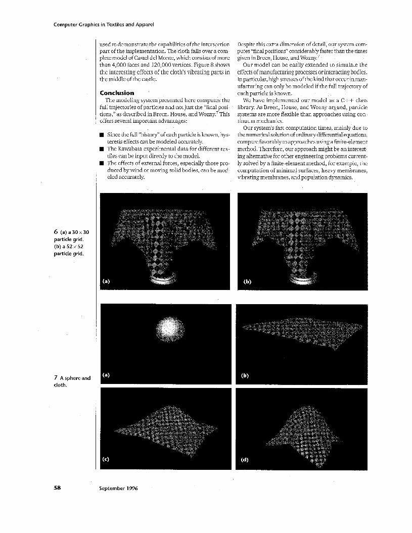
As another example, we calculated a 30 x 30 and a 52 x 52 particle grid and draped the cloth over a round table. The resulting images, in Figures 6a and 6b respec- tively (next page), do notjustify the higher particle num- ber. Therefore, it might be possible to calculate an approximate location of the cloth with a low resolution and the final position with a refinement where necessary.
Yet another computation can be seen in Figure 7, where we have draped the cloth over a sphere.
Caste1 del Monte, a castle in the south of Italy, was
IEEE Computer Graphics and Applications
5 Sequenceof a simulated falling tablecloth at (a) 0.16, (b) 0.28, and (c) 1.08 seconds. In (d), the tablecloth in (c) is shown with a different texture.
57
Computer Graphics in Textiles and Apparel
6 (a)a30x30 particle grid. (b) a 52 x 52 particle grid.
7 A sphere and cloth.
58
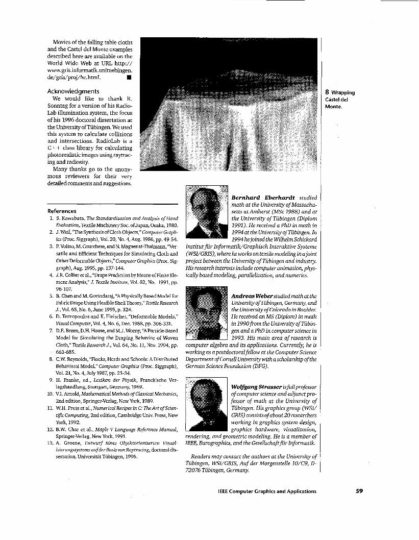
used to demonstrate the capabilities of the intersection part of the implementation. The cloth falls over a com- plete model of Caste1 del Monte, which consists of more than 4,000 faces and 120,000 vertices. Figure 8 shows the interesting effects of the cloths vibrating parts in the middle of the castle.
Conclusion The modeling system presented here computes the
full trajectories of particles and not just the “final posi- tions,” as described in Breen, House, and W ~ z n y . ~ This offers several important advantages:
Since the full “history” of each particle is known, hys- teresis effects can be modeled accurately. The Kawabata experimental data for different tex- tiles can be input directly to the model. The effects of external forces, especially those pro- duced by wind or moving solid bodies, can be mod- eled accurately.
Despite this extra dimension of detail, our system com- putes “final positions” considerably faster than the times given in Breen, House, and W ~ z n y . ~
Our model can be easily extended to simulate the effects of manufacturing processes or interacting bodies. In particular, high stresses of the kind that occur in man- ufacturing can only be modeled if the full trajectory of each particle is known.
We have implemented our model as a C + + class library. As Breen, House, and Wozny argued, particle systems are more flexible than approaches using con- tinuum mechanics.
Our system’s fast computation times, mainly due to the numerical solution of ordinary differential equations, compare favorably to approaches using a finite-element method. Therefore, our approach might be an interest- ing alternative for other engineering problems current- ly solved by a finite-element method, for example, the computation of minimal surfaces, heavy membranes, vibrating membranes, and population dynamics.
September 1996
Movies of the falling table cloths and the Castel del Monte examples described here are available on the World Wide Web at URL http:// www.gris.informatik.unituebingen. de/gris/proj/hc. html.
Acknowledgments We would like to thank R.
Sonntag for a version of his Radio- Lab illumination system, the focus of his 1996 doctoral dissertation at the University of Tubingen. We used this system to calculate collisions and intersections. RadioLab is a C+ + class library for calculating photorealistic images using raytrac- ing and radiosity.
Many thanks go to the anony- mous reviewers for their very detailed comments and suggestions.
References 1. S. Kawabata, The Standardization and Analysis of Hand
Evaluation, Textile Machinery Soc. of Japan, Osaka, 1980. 2. J. Weil, “The Synthesis of Cloth Objects,” Computer Graph-
ics (Proc. Siggraph), Vol. 20, No. 4, Aug. 1986, pp. 49-54. 3. P. Volino, M. Courchese, and N. Magnenat-Thalmann, “Ver-
satile and Efficient Techniques for Simulating Cloth and Other Deformable Objects,” Computer Graphics (Proc. Sig- graph), Aug. 1995, pp. 137-144.
4. J.R. Collier et al., “Drape Prediction by Means of Finite Ele- ment Analysis,” J. Textile Institute, Vol. 82, No. 1991, pp.
5. B. Chen and M. Govindaraj, “A Physically Based Model for Fabric Drape Using Flexible Shell Theory,” Textile Research J., Vol. 65, No. 6, June 1995, p. 324.
6. D. Terzopoulos and K. Fleischer, “Deformable Models,” Visual Computer, Vol. 4, No. 6, Dec. 1988, pp. 306-331.
7. D.E.Breen, D.H. House, andM.J. Wozny, “AParticle-Based Model for Simulating the Draping Behavior of Woven Cloth,” TextileResearchJ., Vol. 64, No. 11, Nov. 1994, pp.
8. C.W. Reynolds, “Flocks, Herds and Schools: ADistributed Behavioral Model,” Computer Graphics (Proc. Siggraph),
9. H. Franke, ed., Lexikon der Physik, Franck’sche Ver- lagshandlung, Stuttgart, Germany, 1969.
10. V.I. Arnold, Mathematical Methods of Classical Mechanics, 2nd edition, Springer-Verlag, New York, 1989.
11. W.H. Press et al., NumericalRecipes in C: The Art of Scien- tific Computing, 2nd edition, Cambridge Univ. Press, New York, 1992.
12. B.W. Char et al., Maple V Language Reference Manual, Springer-Verlag, New York, 1991.
13. A. Groene, Entwurf Eines Objektorientierten Visual- isierungssystems auf der Basis vonRaytracing, doctoral dis- sertation, Universitat Tubingen, 1996.
96-107.
663-685.
VO~. 21, NO. 4, July 1987, pp. 25-34.
B e r n h a r d E b e r h a r d t studied math at the University of Massachu- setts atAmherst (MSc 1988) and at the University of Tubingen (Diplom 1991). He received a PhD in math in 1994 at the Universityof Tubingen. In 1994 hejoined the WilhelmSchickard
Institut f i r Informatik/Graphisch lnteraktive Systeme (WSVGRIS), where he works on textile modeling in a joint project between the University of Tubingen and industry. His research interests include computer animation, phys- ically based modeling, parallelization, and numerics.
Andreas Weberstudied mathatthe Universityof Tubingen, Germanx and the University of Colorado in Boulder. He received an MS (Diplom) in math in 1990from the University of Tubin- gen and a PhD in computer science in 1993. His main area of research is
computer algebra and its applications. Currentb, he is working as a postdoctoral fellow at the Computer Science Department of Cornell University with a scholarship of the German Science Foundation (DFG).
WoZ&angStrasser isfullprofessor of computer science and adjunctpro- fessor of math at the University of Tubingen. His graphics group (WSV GRIS) consists of about20 researchers working in graphics system design, graphics hardware, visualization,
rendering, and geometric modeling. He is a member of IEEE, Eurographics, and the Gesellschaftfiir Informatik.
Readers may contact the authors at the University of Tubingen, WSI/GlUS, Auf der Morgenstelle lO/C9, D- 72076 Tubingen, Germany.
IEEE Computer Graphics and Applications
8 Wrapping Castel del Monte.
59